EP1228712A2 - Disposable surgical gown of back-closable type - Google Patents
Disposable surgical gown of back-closable type Download PDFInfo
- Publication number
- EP1228712A2 EP1228712A2 EP02250471A EP02250471A EP1228712A2 EP 1228712 A2 EP1228712 A2 EP 1228712A2 EP 02250471 A EP02250471 A EP 02250471A EP 02250471 A EP02250471 A EP 02250471A EP 1228712 A2 EP1228712 A2 EP 1228712A2
- Authority
- EP
- European Patent Office
- Prior art keywords
- gown
- regions
- circumferential direction
- rear bodies
- front body
- Prior art date
- Legal status (The legal status is an assumption and is not a legal conclusion. Google has not performed a legal analysis and makes no representation as to the accuracy of the status listed.)
- Granted
Links
Images







Classifications
-
- A—HUMAN NECESSITIES
- A41—WEARING APPAREL
- A41D—OUTERWEAR; PROTECTIVE GARMENTS; ACCESSORIES
- A41D13/00—Professional, industrial or sporting protective garments, e.g. surgeons' gowns or garments protecting against blows or punches
- A41D13/12—Surgeons' or patients' gowns or dresses
- A41D13/1209—Surgeons' gowns or dresses
-
- A—HUMAN NECESSITIES
- A41—WEARING APPAREL
- A41D—OUTERWEAR; PROTECTIVE GARMENTS; ACCESSORIES
- A41D2400/00—Functions or special features of garments
- A41D2400/44—Donning facilities
-
- Y—GENERAL TAGGING OF NEW TECHNOLOGICAL DEVELOPMENTS; GENERAL TAGGING OF CROSS-SECTIONAL TECHNOLOGIES SPANNING OVER SEVERAL SECTIONS OF THE IPC; TECHNICAL SUBJECTS COVERED BY FORMER USPC CROSS-REFERENCE ART COLLECTIONS [XRACs] AND DIGESTS
- Y10—TECHNICAL SUBJECTS COVERED BY FORMER USPC
- Y10T—TECHNICAL SUBJECTS COVERED BY FORMER US CLASSIFICATION
- Y10T24/00—Buckles, buttons, clasps, etc.
- Y10T24/40—Buckles
- Y10T24/4088—One-piece
-
- Y—GENERAL TAGGING OF NEW TECHNOLOGICAL DEVELOPMENTS; GENERAL TAGGING OF CROSS-SECTIONAL TECHNOLOGIES SPANNING OVER SEVERAL SECTIONS OF THE IPC; TECHNICAL SUBJECTS COVERED BY FORMER USPC CROSS-REFERENCE ART COLLECTIONS [XRACs] AND DIGESTS
- Y10—TECHNICAL SUBJECTS COVERED BY FORMER USPC
- Y10T—TECHNICAL SUBJECTS COVERED BY FORMER US CLASSIFICATION
- Y10T24/00—Buckles, buttons, clasps, etc.
- Y10T24/40—Buckles
- Y10T24/4088—One-piece
- Y10T24/4093—Looped strap
Definitions
- This invention relates to a disposable surgical gown of back-closable type.
- Japanese Patent Application Publication No. 1994-207301A discloses a disposable surgical gown of back-closable type comprising a basic body consisting of a front body and first and second rear bodies separated from each other in a circumferential direction with respect to a wearer's torso, a pair of sleeves attached to a pair of shoulder regions, respectively, and first and second belt strips adapted to bind the first and second rear bodies together.
- first and second belt strips are connected to the gown in a range extending from right or left lateral trunk to the backside and a belt loop for the first belt strip is provided in a range extending from left or right lateral trunk to the backside.
- a wearer develops the first and second rear bodies to the circumferential direction so as to be spaced from each other in order to open the backside and, after the arms have been inserted into the respective sleeves, places the first and second rear bodies upon each other in order to close the backside.
- the wearer guides the first belt strip through the belt loop, then ties free ends of the first and second belt strips together, and finally engages the hook member with the loop member to close the neck hole.
- the first and second rear bodies must be developed in the circumferential direction when the arms are inserted into the respective sleeves and handling of the gown is correspondingly troublesome.
- a disposable surgical gown of back-closable type comprising a basic body composed of a front body, first and second rear bodies separated from each other in a circumferential direction with respect to wearer's torso and a pair of sleeves connected to a pair of shoulder regions of the basic body, respectively.
- the disposable surgical gown further comprises the gown is offered in a state prior to actual use thereof such that the first and second rear bodies are developed in the circumferential direction so as to be spaced from each other and folded back onto the front body so that respective free side edge regions of these rear bodies extending in a longitudinal direction may lie on the side of the outer surface of the front body, and the free side edges are connected to each other by a tape member extending in the circumferential direction and having its transversely opposite side regions bonded to the free side edge regions at longitudinally middle zones of the free side edge regions wherein a perforation extends across the tape member in the longitudinal direction between the transversely opposite side regions so that said tape member may be separated along the perforation in the circumferential direction.
- the tape member has a transversely middle zone extending in the circumferential direction between the transversely opposite side regions and, on both sides of the middle zone, a pair of perforations extend in the longitudinal direction so that the middle zone may be cut off from the transversely opposite side regions along the perforations.
- the gown is provided with a female fastener member and a male fastener member adapted to be detachably engaged with each other to fasten the first and second rear bodies together and wherein the female fastener member is attached to the basic body at an appropriate location in its longitudinally middle region while the male fastener member is attached to one of the transversely opposite side regions of the tape member.
- the female fastener member is one of a hook member and a loop member constituting together so-called mechanical fastener and the male fastener member is the other.
- Fig. 1 is a perspective view showing an embodiment 1A of a disposable surgical gown as viewed from the side of its front body 5
- Fig. 2 is a perspective view showing the same gown 1A as viewed from its back
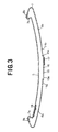
- Fig. 3 is a cross-sectional view taken along the line A - A in Fig. 1 with its wearer's body on the left side of the front body 5.
- a circumferential direction with respect to a wearer's waist is indicated by a double-headed arrow x and a longitudinal direction with respect to the wearer's body is indicated by a double-headed arrow Y.
- a front body 5 and first and second rear bodies 6a, 6b referred to herein as inner surfaces should be understood to be the surfaces facing a wearer's skin of the gown 1A.
- Surfaces of these bodies 5, 6a, 6b referred to herein as outer surfaces should be understood to be the surfaces facing away from the wearer's skin of the gown 1A.
- the gown 1A is worn by a medical staff-member such as a surgeon and a nurse during an operation.
- the gown 1A comprises a basic body 2 which is relatively long in the longitudinal direction and a pair of sleeves 4 attached to respective shoulder regions 3 of the basic body 2.
- the basic body 2 comprises, in turn, the front body 5 and, the first and second rear bodies 6a, 6b separated from each other in the circumferential direction.
- transversely opposite side edge regions 7a, 7b of the front body 5 extending in the longitudinal direction are respectively bonded to respective fixed side edges 8a, 8b of the first and second rear bodies 6a, 6b so that the front body 5 may be integrally connected to the first and second rear bodies 6a, 6b.
- a neck hole 9 is formed between the shoulder regions 3 of the basic body 2.
- Each of the sleeves 4 is tapered from its sleeve head seam 11 toward its lower sleeve edge 10 and a peripheral edge of the sleeve head seam 11 is bonded to a peripheral edge of an associated arm hole 12 of the basic body 2.
- the lower sleeve edge 10 is provided with a cuff 13 which is elastically stretchable in its circumferential direction.
- the gown 1A Prior to actual use, the gown 1A is stored in such a state that the first and second rear bodies 6a, 6b are developed in the circumferential direction so as to be spaced from each other and folded back onto the front body 5. In this state, respective free side edge regions 14a, 14b of these rear bodies 6a, 6b extending in the longitudinal direction lie on the outer surface of the front body 5.
- a tape member 15 extends in the circumferential direction to connect these free side edge portions 14a, 14b to each other.
- the tape member 15 lies in longitudinally middle zones of the free side edge regions 14a, 14b of the first and second rear bodies 6a, 6b and has transversely opposite side regions 15a, 15b.
- the side region 15a is partially bonded to the free side edge region 14a of the first rear body 6a and the side region 15b is partially bonded to the free side edge region 14b of the second rear body 6b.
- a perforation 16 extends in the longitudinal direction so that the tape member 15 may be separated in the circumferential direction in two.
- the tape member 15 retains the gown 1A in such a state as the first and second rear bodies 6a, 6b are folded back onto the front body 5 (i.e., the backside of the basic body 2 is opened in the circumferential direction).
- the side region 15b of the tape member 15 is provided with a hook member 17 as one component of a so-called mechanical fastener-
- the side edge region 7a of the front body 5 is provided in its longitudinally middle zone with a loop member 18 adapted to be detachably engaged with the hook member 17.
- the first rear body 6a is provided at its upper part with a hook member 19 and the second rear body 6b is provided at its upper part with a loop member 20 adapted to be detachably engaged with the hook member 19.
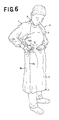
- Figs. 4, 5 and 6 are explanatory drawings illustrating a sequence in which the gown 1A of Fig. 1 is worn.
- a wearer may insert his or her arms into the sleeves 4 of the gown 1A, respectively, then hold the transversely opposite side regions 15a, 15b of the tape member 15 with the fingers to cut off the tape member 15 in two along the perforation 16 and separate these halves in the circumferential direction.
- the wearer may unfold the first and second rear bodies 6a, 6b from the side of the front body 5 toward the backside as will be best seen in Fig. 5. Then, holding the side region 15b of the tape member 15 as will be best seen in Fig. 6, the wearer may place the free side edge region 14b of the second rear body 6b upon the outer surface of the free side edge region 14a of the first rear body 6a and engage the hook member 17 with the loop member 18 to close the backside. Thereafter, the wearer may engage the hook member 19 with the loop member 20 to close the neck hole 9.
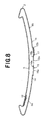
- Fig. 7 is a perspective view showing another embodiment 1B of the surgical gown as viewed from the side of its front body 5 and Fig. 8 is a cross-sectional view taken along the line B - B in Fig. 7 with its wearer's body on the left side of the front body 5.
- the gown of Fig. 7 is similar to the gown of Fig. 1 except an arrangement as follows:
- the basic body 2 comprises the front body 5 and the first and second rear bodies 6a, 6b being integrally continuous one to another wherein the tape member 15 lies in the longitudinally middle zones of the free side edge regions 14a, 14b of the first and second rear bodies 6a, 6b and extends in the circumferential direction between the free side edge regions 14a, 14b.
- the tape member 15 has transversely opposite side regions 15a, 15b lying adjacent to the free side edge regions 14a, 14b of the first and second rear bodies 6a, 6b, respectively, and a middle region 15c extending between the side regions 15a, 15b.
- the side regions 15a, 15b are partially bonded to the free side edge regions 14a, 14b, respectively.
- a pair of perforations 16a, 16b extend in the longitudinal direction, along which the middle region 15c can be cut off from the side regions 15a, 15b.
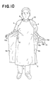
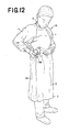
- Figs. 9, 10, 11 and 12 are explanatory drawings illustrating a sequence in which the gown 1B is worn.
- a wearer may insert his or her arms into the sleeves 4 of the gown 1B, respectively, then hold the side region 15a and the middle region 15c of the tape member 15 with the fingers to cut off the tape member 15 in two along the perforation 16a as will be seen in Fig. 9.
- the wearer may unfold the first and second rear bodies 6a, 6b from the side of the front body 5 toward the backside.
- the wearer may hand the middle region 15c cut off from the tape member 15 over to a helper who may then, holding the middle region 15c of the tape member 15 with the fingers, unfold the second rear body 6b toward the wearer's backside and make the wearer hold the side region 15b which is contiguous to the middle region 15c .
- the wearer and the helper cooperate each other to cut off the side region 15b and the middle region 15c held by them along the other perforation 16b.
- the wearer may place the free side edge region 14b of the second rear body 6b now lying on the backside upon the outer surface of the free side edge region 14a of the first rear body 6a and then engage the hook member 19 with the loop member 20 to close the neck hole 9.
- the helper may engage the hook member 19 with the loop member 18 to close the backside.
- the middle region 15c of the tape member 15 having been cut off from the side regions 15a, 15b may be thrown away by the helper.
- both the gown 1A and the gown 1B are free from an anxiety that the outer surfaces of the front body 5 as well as the first and second rear bodies 6a, 6b might come in contact with clothes and skin of the wearer when the gown is worn. This is for the reason that, as will be apparent from Figs. 1 and 7, the first and second rear bodies 6a, 6b are in advance folded back onto the front body 5, i.e., the respective outer surfaces of these rear bodies 6a, 6b face the outer surface of the front body 5 and the respective inner surfaces of them face outward of the gown 1A, 1B before the gown 1A, 1B is actually worn.
- hydrophobic fibrous nonwoven fabric made of thermoplastic synthetic resin fiber, two-layered hydrophobic fibrous nonwoven fabric or a composite sheet comprising a flexible, air-pervious but liquid-impervious thermoplastic synthetic resin film sandwiched by hydrophobic fibrous nonwoven fabric may be used.
- Nonwoven fabric may be selected from a group including products obtained by spun lace-, needle punch-, melt blown-, thermal bond-, spun bond- and chemical bond-process. It is also possible to use a composite nonwoven fabric comprising a melt blown nonwoven fabric having a high water-resistant property sandwiched by a spun bond nonwoven fabric having high strength and flexibility.
- Component fiber of the nonwoven fabric may be selected from a group consisting of polyolefine-, polyester-, polyamide-based fibers and core-sheath-type or side-by-side conjugated fiber of polyethylene/polypropylene or polyethylene/polyester. It is also possible for the nonwoven fabric to be made mixed with cellulose-based fiber such as fluff pulp, rayon or acetate fiber.
- a flexible plastic sheet made of polyethylene, polypropylene, polyethylene terephthalate, polyester.
- Bonding of the front body 5 to the first and second rear bodies 6a, 6b as well as attachment of the tape member 15, the hook members 17, 19 and the loop members 18, 20 may be performed using hot melt adhesive or heat welding technique such as heat-sealing or ultrasonic sealing.
- the gown 1A or 1B is provided in various sizes such as S, M, L, LL and, after packaged in sterilizing bag, subjected to a sterilizing process using gaseous organic chemicals or electron beam or radiation.
- the tape member retains the gown in the state such that the first and second rear bodies have been folded back onto the front body (the backside of the basic body 2 has been opened in the circumferential direction) before the gown is actually worn. Therefore, it is unnecessary for the wearer to develop the first and second rear bodies in the circumferential direction so as to be spaced from each other when the gown is actually worn. Handling of the gown is correspondingly facilitated.
- the gown is free from an anxiety that the outer surfaces of the front body as well as the first and second rear bodies might come in contact with cloths and skin of the wearer and be contaminated with various germs when the gown is worn. This is for the reason that the first and second rear bodies are folded back onto the front body 5 in advance prior to actual use of the gown.
Landscapes
- Health & Medical Sciences (AREA)
- General Health & Medical Sciences (AREA)
- Physical Education & Sports Medicine (AREA)
- Engineering & Computer Science (AREA)
- Textile Engineering (AREA)
- Professional, Industrial, Or Sporting Protective Garments (AREA)
- Orthopedics, Nursing, And Contraception (AREA)
- Endoscopes (AREA)
Abstract
Description
Claims (4)
- A disposable surgical gown of back-closable type comprising:a basic body composed of a front body, first and second rear bodies separated from each other in a circumferential direction with respect to a wearer's torso;a pair of sleeves connected to a pair of shoulder regions of said basic body, respectively;said gown being offered in a state prior to actual use thereof such that said first and second rear bodies are developed in said circumferential direction so as to be spaced from each other and folded back onto said front body so that respective free side edge regions of said rear bodies extend in a longitudinal direction lie on a side of an outer surface of an front body; andsaid free side edge regions being connected to each other by a tape member extending in said circumferential direction and having its transversely opposite side regions bonded to said free side edge regions at longitudinally middle zones of said free side edge regions wherein a perforation extends across said tape member in said longitudinal direction between said transversely opposite side regions so that said tape member is separated along said perforation in said circumferential direction.
- The surgical gown according to Claim 1, wherein said tape member has a transversely middle zone extending in said circumferential direction between said transversely opposite side regions and, on both sides of said middle zone, a pair of perforations extend in said longitudinal direction so that said middle zone is cut off from said transversely opposite side regions along said perforations.
- The surgical gown according to Claim 1, wherein said gown is provided with a female fastener member and a male fastener member adapted to be detachably engaged with each other to fasten said first and second rear bodies together and wherein said female fastener member is attached to said basic body at an appropriate location in its longitudinally middle region while said male fastener member is attached to one of the transversely opposite side regions of said tape member.
- The surgical gown according to Claim 2, wherein said female fastener member is one of a hook member and a loop member constituting together a mechanical fastener and said male fastener member is the other.
Applications Claiming Priority (2)
| Application Number | Priority Date | Filing Date | Title |
|---|---|---|---|
| JP2001016895A JP3691396B2 (en) | 2001-01-25 | 2001-01-25 | Closed back-type disposable outer garment |
| JP2001016895 | 2001-01-25 |
Publications (3)
| Publication Number | Publication Date |
|---|---|
| EP1228712A2 true EP1228712A2 (en) | 2002-08-07 |
| EP1228712A3 EP1228712A3 (en) | 2003-07-16 |
| EP1228712B1 EP1228712B1 (en) | 2005-09-07 |
Family
ID=18883186
Family Applications (1)
| Application Number | Title | Priority Date | Filing Date |
|---|---|---|---|
| EP02250471A Expired - Lifetime EP1228712B1 (en) | 2001-01-25 | 2002-01-25 | Disposable surgical gown of back-closable type |
Country Status (7)
| Country | Link |
|---|---|
| US (1) | US6564386B2 (en) |
| EP (1) | EP1228712B1 (en) |
| JP (1) | JP3691396B2 (en) |
| CN (1) | CN1208000C (en) |
| AT (1) | ATE303732T1 (en) |
| DE (1) | DE60205956T2 (en) |
| TW (1) | TW543378U (en) |
Families Citing this family (46)
| Publication number | Priority date | Publication date | Assignee | Title |
|---|---|---|---|---|
| US20070192947A1 (en) * | 2003-07-10 | 2007-08-23 | Cylena Medical Technologies Inc. | Protective apparel with improved doffing |
| US20050108813A1 (en) * | 2003-07-10 | 2005-05-26 | Cylena Medical Technologies Inc. | Protective apparel spacers and low resistance air flow |
| US20050132463A1 (en) * | 2003-12-19 | 2005-06-23 | Kimberly-Clark Worldwide, Inc. | Surgical gown having adhesive tabs and methods of use |
| US20050132465A1 (en) * | 2003-12-19 | 2005-06-23 | Kimberly-Clark Worldwide, Inc. | Surgical gown having an adhesive tab and methods of use |
| IES20050227A2 (en) * | 2004-04-16 | 2006-05-17 | Anne Butterly | An absorbent article |
| US7305716B1 (en) * | 2004-08-27 | 2007-12-11 | Richards Harlan J | Separable hospital gown |
| US7234171B2 (en) * | 2004-09-30 | 2007-06-26 | Kimberly-Clark Worldwide, Inc. | Expandable material for use in a garment |
| US20060107434A1 (en) * | 2004-09-30 | 2006-05-25 | Kimberly-Clark Worldwide, Inc. | Expandable material for use in a garment |
| US7424750B2 (en) * | 2005-06-13 | 2008-09-16 | Kerr Brian C | Hospital gown with enhanced privacy features |
| US7802313B2 (en) * | 2005-07-12 | 2010-09-28 | Medline Industries, Inc. | Surgical gowns and other protective apparel having color-coding for identifying barrier protection levels and methods of making same |
| US7686791B2 (en) * | 2007-03-07 | 2010-03-30 | Richard F Ramage | Emesis container |
| US7947024B2 (en) * | 2007-03-07 | 2011-05-24 | Richard F. Ramage and Anthony F. Ramage | Emesis container |
| US10271916B2 (en) | 2008-08-08 | 2019-04-30 | Medline Industries, Inc. | Zip strip draping system and methods of manufacturing same |
| US10039610B2 (en) | 2008-08-08 | 2018-08-07 | Medline Industries, Inc. | Zip strip draping system and methods of manufacturing same |
| US7971274B2 (en) * | 2009-06-01 | 2011-07-05 | Salus Corporation | Over the head, full coverage disposable medical gown |
| US20100313326A1 (en) * | 2009-06-11 | 2010-12-16 | Craig Turner | Outer garment |
| KR101116315B1 (en) | 2009-09-10 | 2012-03-13 | (주)아원 | Disposable protection gown |
| KR101116311B1 (en) | 2009-09-10 | 2012-03-13 | (주)아원 | Disposable protection gown |
| US9937015B2 (en) | 2011-05-26 | 2018-04-10 | Medline Industries, Inc. | Surgical drape configured for peripherally inserted central catheter procedures |
| US9820751B2 (en) | 2011-05-26 | 2017-11-21 | Medline Industries, Inc. | Surgical drape configured for peripherally inserted central catheter procedures |
| US9241547B2 (en) * | 2011-10-10 | 2016-01-26 | Central Lake Armor Express, Inc. | Closure assembly incorporating an easy access tab integrated into hook and loop fastener elements and method for forming the same |
| USD779156S1 (en) | 2011-10-18 | 2017-02-21 | Medline Industries, Inc. | Medical gown |
| USD785284S1 (en) | 2011-10-18 | 2017-05-02 | Medline Industries, Inc. | Medical gown |
| USD836297S1 (en) | 2011-10-18 | 2018-12-25 | Medline Industries, Inc. | Medical gown |
| USD821704S1 (en) | 2011-10-18 | 2018-07-03 | Medline Industries, Inc. | Medical gown |
| USD774729S1 (en) | 2011-10-18 | 2016-12-27 | Medline Industries, Inc. | Medical gown |
| US10455872B2 (en) | 2011-10-18 | 2019-10-29 | Medline Industries, Inc. | Disposable medical gown |
| CA144409S (en) | 2011-10-18 | 2013-06-18 | Medline Ind Inc | Medical gown |
| USD863727S1 (en) | 2011-10-18 | 2019-10-22 | Medline Industries, Inc. | Medical gown |
| US10441010B2 (en) | 2011-10-18 | 2019-10-15 | Medline Industries, Inc. | Disposable medical gown |
| USD791434S1 (en) | 2011-10-18 | 2017-07-11 | Medline Industries, Inc. | Medical gown |
| US20130318682A1 (en) * | 2012-06-02 | 2013-12-05 | ICP Medical, LLC, a Delaware Limited Liability Company | Disposable medical gowns |
| USD736493S1 (en) | 2013-03-14 | 2015-08-18 | Medline Industries, Inc. | Medical gown |
| USD741044S1 (en) | 2013-03-14 | 2015-10-20 | Medline Industries, Inc. | Disposable medical gown |
| US11116263B2 (en) * | 2013-11-21 | 2021-09-14 | Medline Industries, Inc. | Gown for self-donning while maintaining sterility and methods therefor |
| US20150158663A1 (en) * | 2013-12-10 | 2015-06-11 | Jeanette Bonfiglio | Maternity kit including delivery and hospital gown with magnetic fasteners |
| US9999265B2 (en) | 2015-03-27 | 2018-06-19 | Joanne P. Monardo | Adjustable privacy gown |
| JP6367500B2 (en) | 2016-05-04 | 2018-08-01 | アヴェント インコーポレイテッド | Disposable surgical gown |
| US11583013B2 (en) | 2016-07-29 | 2023-02-21 | O&M Halyard, Inc. | Collar for a disposable surgical gown |
| USD876751S1 (en) | 2018-05-14 | 2020-03-03 | Allegiance Corporation | Medical gown |
| USD876048S1 (en) * | 2018-05-14 | 2020-02-25 | Allegiance Corporation | Medical gown |
| US11528947B2 (en) | 2018-08-24 | 2022-12-20 | O&M Halyard, Inc. | Personal protection and ventilation system |
| AU2019323823B2 (en) | 2018-08-24 | 2024-09-26 | O&M Halyard, Inc. | Personal protection and ventilation system |
| USD932136S1 (en) * | 2019-01-18 | 2021-10-05 | Inha University Research And Business Foundation | Disposable medical gown |
| USD984085S1 (en) * | 2021-05-14 | 2023-04-25 | Fumiko Fujii | Surgical apparel |
| CN114747826B (en) * | 2022-05-30 | 2025-10-03 | 广东快裕达自动化科技有限公司 | Fully automatic surgical gown production line |
Family Cites Families (14)
| Publication number | Priority date | Publication date | Assignee | Title |
|---|---|---|---|---|
| US3864757A (en) * | 1972-09-25 | 1975-02-11 | Kendall & Co | Belt retainer |
| US3843971A (en) * | 1973-07-23 | 1974-10-29 | Kimberly Clark Co | System and method for obtaining closure of sterile backed surgical gowns |
| US4019207A (en) * | 1976-05-28 | 1977-04-26 | Will Ross, Inc. | Surgical gown belting means |
| US4290148A (en) * | 1980-03-14 | 1981-09-22 | Roberts Fred A | Surgical gown |
| US4370782A (en) * | 1980-08-25 | 1983-02-01 | The Kendall Company | Belt retainer |
| US4371986A (en) * | 1982-04-22 | 1983-02-08 | The Kendall Company | Disposable garment |
| US4369527A (en) * | 1982-04-22 | 1983-01-25 | The Kendall Company | Disposable garment with card loop |
| US4451931A (en) * | 1982-09-23 | 1984-06-05 | The Kendall Company | Disposable garment with card tongue |
| US4558468A (en) * | 1984-10-05 | 1985-12-17 | The Kendall Company | Surgical gown having one-piece-belt system |
| US4982448A (en) * | 1989-04-06 | 1991-01-08 | Work Wear Corporation, Inc. | Surgical gown with transfer card |
| US5140708A (en) * | 1990-03-10 | 1992-08-25 | Repack Surgical Enterpises, Inc. | Surgical gowns and pass cards therefor |
| JP3167815B2 (en) | 1993-01-12 | 2001-05-21 | ユニ・チャーム株式会社 | Surgical outerwear |
| JP2999983B2 (en) * | 1997-07-15 | 2000-01-17 | 大衛株式会社 | Surgical gown |
| US6049907A (en) * | 1998-01-26 | 2000-04-18 | Allegiance Corporation | Gown tie |
-
2001
- 2001-01-25 JP JP2001016895A patent/JP3691396B2/en not_active Expired - Fee Related
-
2002
- 2002-01-23 TW TW091200639U patent/TW543378U/en not_active IP Right Cessation
- 2002-01-25 DE DE60205956T patent/DE60205956T2/en not_active Expired - Lifetime
- 2002-01-25 EP EP02250471A patent/EP1228712B1/en not_active Expired - Lifetime
- 2002-01-25 CN CNB021062099A patent/CN1208000C/en not_active Expired - Fee Related
- 2002-01-25 US US10/054,912 patent/US6564386B2/en not_active Expired - Lifetime
- 2002-01-25 AT AT02250471T patent/ATE303732T1/en not_active IP Right Cessation
Also Published As
| Publication number | Publication date |
|---|---|
| JP2002220713A (en) | 2002-08-09 |
| DE60205956D1 (en) | 2005-10-13 |
| DE60205956T2 (en) | 2006-06-22 |
| EP1228712B1 (en) | 2005-09-07 |
| EP1228712A3 (en) | 2003-07-16 |
| US6564386B2 (en) | 2003-05-20 |
| US20020095709A1 (en) | 2002-07-25 |
| CN1370480A (en) | 2002-09-25 |
| ATE303732T1 (en) | 2005-09-15 |
| CN1208000C (en) | 2005-06-29 |
| JP3691396B2 (en) | 2005-09-07 |
| TW543378U (en) | 2003-07-21 |
Similar Documents
| Publication | Publication Date | Title |
|---|---|---|
| US6564386B2 (en) | Disposable surgical gown of back-closable type | |
| EP1230864B1 (en) | Disposable underwear | |
| US6378136B2 (en) | Disposable gown | |
| RU2203644C2 (en) | Absorbing product, such as nappy, protective product at incontinence or analogous one including means for capturing | |
| EP1224876B1 (en) | Disposable surgical gown | |
| KR100884838B1 (en) | Disposable diapers | |
| EP1559387A1 (en) | Disposable wearing article | |
| EP1147718A2 (en) | Disposable gown | |
| US3843971A (en) | System and method for obtaining closure of sterile backed surgical gowns | |
| MX2009000135A (en) | Pants-type wearing article. | |
| US11452320B2 (en) | Over-the-head disposable contact isolation gown and method for making the same | |
| JP2007105183A (en) | Disposable wearing article | |
| KR20080019004A (en) | Disposable Pants Type Wear Items | |
| JP3771466B2 (en) | Disposable wearing items | |
| TWI272939B (en) | Wearing article | |
| EP1163858A2 (en) | Disposable outer garment for surgical operation | |
| CN101170980B (en) | Disposable pull-on wearing article | |
| JP2999983B2 (en) | Surgical gown | |
| CA3047749C (en) | Medical gown | |
| CN101065088B (en) | Disposable panties | |
| KR101251677B1 (en) | DISPOSABLE WEARlNG ARTICLE | |
| JP3167815B2 (en) | Surgical outerwear | |
| JP2002235223A (en) | Back side disposable outer garment | |
| JP4163144B2 (en) | Disposable pants and manufacturing method thereof | |
| WO2014123223A1 (en) | Medical outer garment |
Legal Events
| Date | Code | Title | Description |
|---|---|---|---|
| PUAI | Public reference made under article 153(3) epc to a published international application that has entered the european phase |
Free format text: ORIGINAL CODE: 0009012 |
|
| AK | Designated contracting states |
Kind code of ref document: A2 Designated state(s): AT BE CH CY DE DK ES FI FR GB GR IE IT LI LU MC NL PT SE TR |
|
| AX | Request for extension of the european patent |
Free format text: AL;LT;LV;MK;RO;SI |
|
| PUAL | Search report despatched |
Free format text: ORIGINAL CODE: 0009013 |
|
| AK | Designated contracting states |
Designated state(s): AT BE CH CY DE DK ES FI FR GB GR IE IT LI LU MC NL PT SE TR |
|
| AX | Request for extension of the european patent |
Extension state: AL LT LV MK RO SI |
|
| 17P | Request for examination filed |
Effective date: 20031201 |
|
| AKX | Designation fees paid |
Designated state(s): AT BE CH CY DE DK ES FI FR GB GR IE IT LI LU MC NL PT SE TR |
|
| RAP1 | Party data changed (applicant data changed or rights of an application transferred) |
Owner name: UNI-CHARM CORPORATION |
|
| 17Q | First examination report despatched |
Effective date: 20040603 |
|
| GRAP | Despatch of communication of intention to grant a patent |
Free format text: ORIGINAL CODE: EPIDOSNIGR1 |
|
| GRAS | Grant fee paid |
Free format text: ORIGINAL CODE: EPIDOSNIGR3 |
|
| GRAA | (expected) grant |
Free format text: ORIGINAL CODE: 0009210 |
|
| AK | Designated contracting states |
Kind code of ref document: B1 Designated state(s): AT BE CH CY DE DK ES FI FR GB GR IE IT LI LU MC NL PT SE TR |
|
| PG25 | Lapsed in a contracting state [announced via postgrant information from national office to epo] |
Ref country code: LI Free format text: LAPSE BECAUSE OF FAILURE TO SUBMIT A TRANSLATION OF THE DESCRIPTION OR TO PAY THE FEE WITHIN THE PRESCRIBED TIME-LIMIT Effective date: 20050907 Ref country code: IT Free format text: LAPSE BECAUSE OF FAILURE TO SUBMIT A TRANSLATION OF THE DESCRIPTION OR TO PAY THE FEE WITHIN THE PRESCRIBED TIME-LIMIT;WARNING: LAPSES OF ITALIAN PATENTS WITH EFFECTIVE DATE BEFORE 2007 MAY HAVE OCCURRED AT ANY TIME BEFORE 2007. THE CORRECT EFFECTIVE DATE MAY BE DIFFERENT FROM THE ONE RECORDED. Effective date: 20050907 Ref country code: CH Free format text: LAPSE BECAUSE OF FAILURE TO SUBMIT A TRANSLATION OF THE DESCRIPTION OR TO PAY THE FEE WITHIN THE PRESCRIBED TIME-LIMIT Effective date: 20050907 Ref country code: FI Free format text: LAPSE BECAUSE OF FAILURE TO SUBMIT A TRANSLATION OF THE DESCRIPTION OR TO PAY THE FEE WITHIN THE PRESCRIBED TIME-LIMIT Effective date: 20050907 Ref country code: BE Free format text: LAPSE BECAUSE OF FAILURE TO SUBMIT A TRANSLATION OF THE DESCRIPTION OR TO PAY THE FEE WITHIN THE PRESCRIBED TIME-LIMIT Effective date: 20050907 Ref country code: AT Free format text: LAPSE BECAUSE OF FAILURE TO SUBMIT A TRANSLATION OF THE DESCRIPTION OR TO PAY THE FEE WITHIN THE PRESCRIBED TIME-LIMIT Effective date: 20050907 |
|
| REG | Reference to a national code |
Ref country code: GB Ref legal event code: FG4D |
|
| REG | Reference to a national code |
Ref country code: CH Ref legal event code: EP |
|
| REG | Reference to a national code |
Ref country code: IE Ref legal event code: FG4D |
|
| REF | Corresponds to: |
Ref document number: 60205956 Country of ref document: DE Date of ref document: 20051013 Kind code of ref document: P |
|
| PG25 | Lapsed in a contracting state [announced via postgrant information from national office to epo] |
Ref country code: GR Free format text: LAPSE BECAUSE OF FAILURE TO SUBMIT A TRANSLATION OF THE DESCRIPTION OR TO PAY THE FEE WITHIN THE PRESCRIBED TIME-LIMIT Effective date: 20051207 Ref country code: DK Free format text: LAPSE BECAUSE OF FAILURE TO SUBMIT A TRANSLATION OF THE DESCRIPTION OR TO PAY THE FEE WITHIN THE PRESCRIBED TIME-LIMIT Effective date: 20051207 |
|
| REG | Reference to a national code |
Ref country code: SE Ref legal event code: TRGR |
|
| PG25 | Lapsed in a contracting state [announced via postgrant information from national office to epo] |
Ref country code: IE Free format text: LAPSE BECAUSE OF NON-PAYMENT OF DUE FEES Effective date: 20060125 |
|
| PG25 | Lapsed in a contracting state [announced via postgrant information from national office to epo] |
Ref country code: LU Free format text: LAPSE BECAUSE OF NON-PAYMENT OF DUE FEES Effective date: 20060131 Ref country code: MC Free format text: LAPSE BECAUSE OF NON-PAYMENT OF DUE FEES Effective date: 20060131 |
|
| PG25 | Lapsed in a contracting state [announced via postgrant information from national office to epo] |
Ref country code: PT Free format text: LAPSE BECAUSE OF FAILURE TO SUBMIT A TRANSLATION OF THE DESCRIPTION OR TO PAY THE FEE WITHIN THE PRESCRIBED TIME-LIMIT Effective date: 20060207 |
|
| REG | Reference to a national code |
Ref country code: CH Ref legal event code: PL |
|
| ET | Fr: translation filed | ||
| PLBE | No opposition filed within time limit |
Free format text: ORIGINAL CODE: 0009261 |
|
| STAA | Information on the status of an ep patent application or granted ep patent |
Free format text: STATUS: NO OPPOSITION FILED WITHIN TIME LIMIT |
|
| 26N | No opposition filed |
Effective date: 20060608 |
|
| REG | Reference to a national code |
Ref country code: IE Ref legal event code: MM4A |
|
| PG25 | Lapsed in a contracting state [announced via postgrant information from national office to epo] |
Ref country code: TR Free format text: LAPSE BECAUSE OF FAILURE TO SUBMIT A TRANSLATION OF THE DESCRIPTION OR TO PAY THE FEE WITHIN THE PRESCRIBED TIME-LIMIT Effective date: 20050907 |
|
| PG25 | Lapsed in a contracting state [announced via postgrant information from national office to epo] |
Ref country code: CY Free format text: LAPSE BECAUSE OF FAILURE TO SUBMIT A TRANSLATION OF THE DESCRIPTION OR TO PAY THE FEE WITHIN THE PRESCRIBED TIME-LIMIT Effective date: 20050907 |
|
| PG25 | Lapsed in a contracting state [announced via postgrant information from national office to epo] |
Ref country code: ES Free format text: LAPSE BECAUSE OF NON-PAYMENT OF DUE FEES Effective date: 20060131 |
|
| PGFP | Annual fee paid to national office [announced via postgrant information from national office to epo] |
Ref country code: FR Payment date: 20130204 Year of fee payment: 12 Ref country code: DE Payment date: 20130123 Year of fee payment: 12 Ref country code: GB Payment date: 20130123 Year of fee payment: 12 Ref country code: SE Payment date: 20130114 Year of fee payment: 12 |
|
| PGFP | Annual fee paid to national office [announced via postgrant information from national office to epo] |
Ref country code: NL Payment date: 20130116 Year of fee payment: 12 |
|
| REG | Reference to a national code |
Ref country code: DE Ref legal event code: R119 Ref document number: 60205956 Country of ref document: DE |
|
| REG | Reference to a national code |
Ref country code: NL Ref legal event code: V1 Effective date: 20140801 |
|
| REG | Reference to a national code |
Ref country code: SE Ref legal event code: EUG |
|
| GBPC | Gb: european patent ceased through non-payment of renewal fee |
Effective date: 20140125 |
|
| REG | Reference to a national code |
Ref country code: DE Ref legal event code: R119 Ref document number: 60205956 Country of ref document: DE Effective date: 20140801 |
|
| PG25 | Lapsed in a contracting state [announced via postgrant information from national office to epo] |
Ref country code: DE Free format text: LAPSE BECAUSE OF NON-PAYMENT OF DUE FEES Effective date: 20140801 Ref country code: NL Free format text: LAPSE BECAUSE OF NON-PAYMENT OF DUE FEES Effective date: 20140801 |
|
| REG | Reference to a national code |
Ref country code: FR Ref legal event code: ST Effective date: 20140930 |
|
| PG25 | Lapsed in a contracting state [announced via postgrant information from national office to epo] |
Ref country code: SE Free format text: LAPSE BECAUSE OF NON-PAYMENT OF DUE FEES Effective date: 20140126 Ref country code: FR Free format text: LAPSE BECAUSE OF NON-PAYMENT OF DUE FEES Effective date: 20140131 Ref country code: GB Free format text: LAPSE BECAUSE OF NON-PAYMENT OF DUE FEES Effective date: 20140125 |