EP1228574B1 - Card connector and portable telephone having the same - Google Patents
Card connector and portable telephone having the same Download PDFInfo
- Publication number
- EP1228574B1 EP1228574B1 EP01906266A EP01906266A EP1228574B1 EP 1228574 B1 EP1228574 B1 EP 1228574B1 EP 01906266 A EP01906266 A EP 01906266A EP 01906266 A EP01906266 A EP 01906266A EP 1228574 B1 EP1228574 B1 EP 1228574B1
- Authority
- EP
- European Patent Office
- Prior art keywords
- card
- contact
- base member
- contact members
- fitting
- Prior art date
- Legal status (The legal status is an assumption and is not a legal conclusion. Google has not performed a legal analysis and makes no representation as to the accuracy of the status listed.)
- Expired - Lifetime
Links
Images

Classifications
-
- G—PHYSICS
- G06—COMPUTING; CALCULATING OR COUNTING
- G06K—GRAPHICAL DATA READING; PRESENTATION OF DATA; RECORD CARRIERS; HANDLING RECORD CARRIERS
- G06K7/00—Methods or arrangements for sensing record carriers, e.g. for reading patterns
- G06K7/0013—Methods or arrangements for sensing record carriers, e.g. for reading patterns by galvanic contacts, e.g. card connectors for ISO-7816 compliant smart cards or memory cards, e.g. SD card readers
- G06K7/0021—Methods or arrangements for sensing record carriers, e.g. for reading patterns by galvanic contacts, e.g. card connectors for ISO-7816 compliant smart cards or memory cards, e.g. SD card readers for reading/sensing record carriers having surface contacts
- G06K7/003—Methods or arrangements for sensing record carriers, e.g. for reading patterns by galvanic contacts, e.g. card connectors for ISO-7816 compliant smart cards or memory cards, e.g. SD card readers for reading/sensing record carriers having surface contacts means for pressing the connector contacts in the direction of the card contacts to assure trustworthy electrical connection between card and connector
-
- H—ELECTRICITY
- H04—ELECTRIC COMMUNICATION TECHNIQUE
- H04B—TRANSMISSION
- H04B1/00—Details of transmission systems, not covered by a single one of groups H04B3/00 - H04B13/00; Details of transmission systems not characterised by the medium used for transmission
- H04B1/38—Transceivers, i.e. devices in which transmitter and receiver form a structural unit and in which at least one part is used for functions of transmitting and receiving
- H04B1/3816—Mechanical arrangements for accommodating identification devices, e.g. cards or chips; with connectors for programming identification devices
-
- H—ELECTRICITY
- H04—ELECTRIC COMMUNICATION TECHNIQUE
- H04M—TELEPHONIC COMMUNICATION
- H04M2250/00—Details of telephonic subscriber devices
- H04M2250/14—Details of telephonic subscriber devices including a card reading device
Definitions
- the present invention relates to a card connector and a portable telephone having the same, and more particularly to a card connector suitable for connection of a subscriber identification module (SIM) card and a portable telephone having the same.
- SIM subscriber identification module
- a contacting device for an identification card disclosed in, for example, Japanese Patent No. 2,574,710 has been known.
- a contacting device for an identification card having contact regions arranged in two rows (A, B), wherein two sets of contact members 81 and 82 having the same length are arranged in an interdigitated manner, and terminations of the contact members 81 and 82 are disposed on the opposite side.
- a contacting device for an identification card having contact regions arranged in two rows (A, B), wherein two sets of contact members 10 and 11 having mutually different lengths are arranged alternately, and terminations of the contact members 10 and 11 are arranged on the same side.
- US-A-5823828 discloses an electrical connector for receiving a card, wherein contact portions of contact members are located so that the card does not collide with the contact members when the card is slidingly fitted.
- WO 98/13784 discloses an electrical connector for receiving a planar electronic module, wherein contact members are disposed such that terminal ends of said contact members are mutually opposing.
- the invention has been devised to overcome the above-described problems, and its object is to provide a card connector capable of effecting stable fixation to the printed circuit board and of preventing the collision at the time of the fitting of the card, as well as a portable telephone having the same.
- a card connector including a base member and two contact members which are provided on the base member and whose one ends serve as joining portions with respect to a circuit board and whose other ends serve as contact portions with respect to a card, wherein the joining portions of the two contact members are respectively disposed at mutually opposite ends of the base member, wherein the contact portions of the two contact members have termination free ends, and wherein when viewed in a direction perpendicular to a card fitting direction, the contact portion of one of the contact members is located between the termination free end and the joining portion of the one of the contact members, and the termination free end of the other of the contact members is located between the joining portion and the contact portion of the other of the contact members.
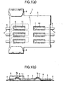
- Figs. 1(a) and 1(b) are diagrams illustrating a card connector in accordance with an embodiment of the invention.
- Fig. 1(a) is a plan view
- Fig. 1(b) is a cross-sectional view.
- a card connector 1 is composed of a plate-like base member 2, two sets of contact members 3 and 4 fixed to the base member 2, and a pair of holding portions 9.
- the base member 2 has a substantially rectangular planar shape, and its left end side is formed to be wide.
- a card is loaded by being slid on the card connector 1 from the right-hand side toward the left-hand side. It should be noted that, in the description that follows, the direction in which the card advances during the loading of the card is assumed to be the forward direction.
- the set of three contact members 3 are formed by thin elongated metal pieces, and joining portions 5 which are soldered to a printed circuit board (not shown) are respectively provided at their ends where the card is fitted, while contact portions 7 which come into contact with the contacts of the card are respectively provided at the other ends.
- Each contact member 3 extends in such a manner as to creep into the interior of the base member 2 from an end face of the base member 2 on the card fitting side thereof and then advance straight. Then, the contact member 3 is exposed from a wall surface of a through hole 10 with a rectangular cross section formed in the base member 2 in correspondence with the contact portion 7.
- the contact member 3 is bent upward from a substantially central portion in the through hole 10, becomes higher than the obverse surface (upper surface) of the base member 2 and forms a peak 7a, and the contact member 3 is subsequently bent downward to its termination.
- the contact portion 7 is bent in a chevron shape and has a termination in the card fitting direction.
- the contact members 4 are formed by thin elongated metal pieces, and joining portions 6 which are soldered to the printed circuit board are respectively provided at their ends away from the card fitting side, while contact portions 8 which come into contact with the contacts of the card are respectively provided at the other ends.
- Each contact member 4 extends in such a manner as to creep into the interior of the base member 2 from an end face opposite to its card fitting side, and the contact member 4 is bent leftward in terms of its advancing direction before a through hole 11 with a rectangular cross section formed in the base member 2 in correspondence with the contact portion 8.
- the contact member 4 advances straight in parallel with the through hole 11, and its direction is reversed after the contact member 4 has gone beyond the through hole 11, and the contact member 4 is exposed from a wall surface of the through hole 11 on the card fitting side thereof. Further, the contact member 4 is bent upward from a substantially central portion of the interior of the through hole 11, becomes higher than the obverse surface (upper surface) of the base member 2 and forms a peak 8a, and the contact member 4 is subsequently bent downward to its termination. In other words, the contact portion 8 is bent in a chevron shape and has a termination in the card fitting direction.
- the provision of the joining portions 6 on the side away from the joining portions 5 and the alignment of the direction of the contact portions 8 with the direction of the contact portions 7 are made compatible.
- the pair of holding portions 9 are respectively attached to both side ends of a widened portion of the base member 2.
- the holding portions 9 are formed by bending a thin metal plate, and their one ends are respectively fixed to the side ends of the widened portion. By virtue of their resiliency, the holding portions 9 press from above and hold both sides of a front portion of the card fitted to the card connector 1.
- both contact portions 7 and 8 become gradually high from the card fitting side, and after forming the peak 8a, they are bent downward up to their terminations, so that a situation does not occur in which the front end of the card 21 collides against the contact portions 7 and 8 and damage the contact portions 7 and 8. It should be noted that a rear end portion of the card 21 is held by, for instance, an inner wall surface of the housing of the portable telephone, as will be described later.
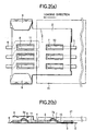
- Fig. 3 is a diagram for explaining the portable telephone having the card connector in accordance with the embodiment of the invention.
- This drawing shows a reverse surface-side housing 31.
- An opening 32 for attaching a cover-cum-battery is formed in this reverse surface-side housing 31 in such a manner as to extend from a substantially central portion to a lower edge thereof.
- a printed circuit board 33 of the main body of the portable telephone is exposed in the opening, and the card connector 1 is fixed on it by soldering.
- a projection is formed in advance at a position which opposes the contact portions 7 when the cover- cum -battery is fitted in the opening 32, so as to hold the rear end portion of the card when the card is fitted.
- the base member 1 can be stably fixed to the printed circuit board.
- the contact portions 7 and 8 are bent in the chevron shape, and have terminations in the card fitting direction, it is possible to prevent the front end of the card from colliding against the contact members at the time of the loading of the card.
- the card connector As described above, in accordance with the invention, it is possible to provide a card connector having excellent advantages in that the card connector can be fixed stably to the circuit board, and that it is possible to prevent the collision of the front end of the card against the contact portions at the time of the fitting of the card.
Description
Claims (5)
- A card connector (1) comprising:wherein the joining portions (5,6) of said two contact members (3,4) are respectively disposed at mutually opposite ends of said base member (2),a base member (2); and,two contact members (3,4) provided on said base member (2), each of said contact members (3,4) including a joining portion (5,6) with respect to a circuit board at a first end thereof and a contact portion (7,8) with respect to a card (21) at a second end thereof,
characterized in that the contact portions (7,8) of said two contact members (3,4) have termination free ends and wherein when viewed in a direction perpendicular to a card fitting direction, the contact portion (7) of one of the contact members (3) is located between the termination free end and the joining portion (5) of the one contact member (3), and the termination free end of another of the contact members (4) is located between the joining portion (6) and the contact portion (8) of the other contact member (4). - The card connector (1) according to claim 1,
wherein the one of the contact members (3) extends from the card-fitting-side end of said base member (2) in a direction toward the card fitting direction, and
wherein the other of the contact members (4) extends from the end opposite to the card-fitting-side end in a direction opposite to the card fitting direction, and has its direction reversed in the card fitting direction. - The card connector (1) according to claim 1,
wherein said base member (2) includes a member (9) for holding the card (21), and
wherein said member (9) for holding the card is disposed at an edge portion of said base member (2) opposite to a card fitting side thereof. - The card connector according to claim 1,
wherein said base member (2) includes a through hole (10,11) corresponding to the contact portion (7,8), and
wherein each of said contact members (3,4) passes from an end face of said base member (2) through an interior of said base member (2), and is exposed to an outside of said base member (2) from the through hole (10,11). - A portable telephone comprising said card connector (1) according to claim 1.
Applications Claiming Priority (3)
| Application Number | Priority Date | Filing Date | Title |
|---|---|---|---|
| JP2000048159A JP2001237010A (en) | 2000-02-24 | 2000-02-24 | Card connector and mobile phone equipped with it |
| JP2000048159 | 2000-02-24 | ||
| PCT/JP2001/001368 WO2001063885A2 (en) | 2000-02-24 | 2001-02-23 | Card connector and portable telephone having the same |
Publications (2)
| Publication Number | Publication Date |
|---|---|
| EP1228574A2 EP1228574A2 (en) | 2002-08-07 |
| EP1228574B1 true EP1228574B1 (en) | 2005-04-13 |
Family
ID=18570283
Family Applications (1)
| Application Number | Title | Priority Date | Filing Date |
|---|---|---|---|
| EP01906266A Expired - Lifetime EP1228574B1 (en) | 2000-02-24 | 2001-02-23 | Card connector and portable telephone having the same |
Country Status (6)
| Country | Link |
|---|---|
| US (1) | US6942154B1 (en) |
| EP (1) | EP1228574B1 (en) |
| JP (1) | JP2001237010A (en) |
| CN (1) | CN1165113C (en) |
| AU (1) | AU3415801A (en) |
| WO (1) | WO2001063885A2 (en) |
Families Citing this family (8)
| Publication number | Priority date | Publication date | Assignee | Title |
|---|---|---|---|---|
| JP3707013B2 (en) | 2002-05-10 | 2005-10-19 | 日本航空電子工業株式会社 | connector |
| KR100486529B1 (en) * | 2002-08-27 | 2005-05-03 | 엘지전자 주식회사 | Sim card terminal contact structure of mobile phone |
| JP4386811B2 (en) | 2004-08-19 | 2009-12-16 | 日本圧着端子製造株式会社 | Memory card socket |
| JP4403040B2 (en) | 2004-08-19 | 2010-01-20 | 日本圧着端子製造株式会社 | Card holder for SIM socket |
| JP4539490B2 (en) * | 2005-08-08 | 2010-09-08 | 日本電気株式会社 | SIM card holding structure and portable terminal device |
| CN2874813Y (en) * | 2005-12-23 | 2007-02-28 | 富士康(昆山)电脑接插件有限公司 | Electric connector |
| SE0700861L (en) * | 2007-04-05 | 2008-07-29 | Straalfors Ab | identity Carriers |
| JP7259378B2 (en) * | 2019-02-12 | 2023-04-18 | I-Pex株式会社 | electrical connector |
Family Cites Families (10)
| Publication number | Priority date | Publication date | Assignee | Title |
|---|---|---|---|---|
| DE59108764D1 (en) | 1990-01-30 | 1997-08-14 | Amphenol Tuchel Elect | Contacting device for an SI module |
| US5503564A (en) * | 1992-10-30 | 1996-04-02 | The Whitaker Corporation | Assembly of an electrical connector and ejector unit for connecting IC cards to printed circuit boards |
| FR2730328B1 (en) * | 1995-02-03 | 1997-04-04 | Connectors Pontarlier | CONNECTOR FOR MICROCIRCUIT CARD READING APPARATUS AND MICROCIRCUIT CARD READING APPARATUS INCLUDING SAME |
| FR2742561B1 (en) * | 1995-12-13 | 1998-01-09 | Itt Composants Instr | ELECTRICAL CONNECTOR FOR AN INTEGRATED CIRCUIT (S) CARD WITH CONTACT |
| WO1998013784A1 (en) | 1996-09-26 | 1998-04-02 | The Whitaker Corporation | Electrical connector for receiving a planar electronic module |
| TW359395U (en) | 1997-07-17 | 1999-05-21 | Acer Peripherals Inc | Receiving apparatus for accepting user identification card |
| US6106317A (en) * | 1997-09-26 | 2000-08-22 | Thomas & Betts International, Inc. | IC chip card connector with pivotally and linearly movable cover |
| JP3272655B2 (en) | 1997-12-26 | 2002-04-08 | 日本圧着端子製造株式会社 | Printed wiring board connector |
| JP3333481B2 (en) * | 1999-11-16 | 2002-10-15 | 山一電機株式会社 | Card recognition switch for card connector |
| US6783926B2 (en) * | 2001-09-15 | 2004-08-31 | Kenneth Reece | Circuit board IC card connector |
-
2000
- 2000-02-23 US US09/980,740 patent/US6942154B1/en not_active Expired - Fee Related
- 2000-02-24 JP JP2000048159A patent/JP2001237010A/en active Pending
-
2001
- 2001-02-23 EP EP01906266A patent/EP1228574B1/en not_active Expired - Lifetime
- 2001-02-23 CN CNB018002447A patent/CN1165113C/en not_active Expired - Fee Related
- 2001-02-23 WO PCT/JP2001/001368 patent/WO2001063885A2/en active IP Right Grant
- 2001-02-23 AU AU34158/01A patent/AU3415801A/en not_active Abandoned
Also Published As
| Publication number | Publication date |
|---|---|
| AU3415801A (en) | 2001-09-03 |
| WO2001063885A2 (en) | 2001-08-30 |
| US6942154B1 (en) | 2005-09-13 |
| WO2001063885A3 (en) | 2002-06-06 |
| EP1228574A2 (en) | 2002-08-07 |
| CN1165113C (en) | 2004-09-01 |
| JP2001237010A (en) | 2001-08-31 |
| CN1389023A (en) | 2003-01-01 |
Similar Documents
| Publication | Publication Date | Title |
|---|---|---|
| EP1247347B1 (en) | Card holding structure and portable terminal apparatus having the same | |
| US6261132B1 (en) | Header connector for future bus | |
| EP0898792B1 (en) | Miniature card edge clip | |
| CN109644557B (en) | Electrical connector | |
| US20040005794A1 (en) | Construction for mounting a terminal, a circuit board connector and method of mounting it | |
| WO2005096456A1 (en) | Connector | |
| US7112072B2 (en) | Ground bus for an electrical connector | |
| US6379176B1 (en) | Flat cable connector for attaching a flat cable to a circuit board | |
| US6692273B1 (en) | Straddle mount connector | |
| US7188408B2 (en) | Method of making a straddle mount connector | |
| EP1228574B1 (en) | Card connector and portable telephone having the same | |
| US20020072264A1 (en) | Connector for plate object with terminals | |
| US5417596A (en) | Multipolar electrical connector for a memory card | |
| US6997752B2 (en) | Connector | |
| JPS5916398B2 (en) | etsugi card connector | |
| JP2005294217A (en) | Insulation displacement contact and electric connector using it | |
| US20040121654A1 (en) | Battery connector | |
| JPH11339906A (en) | Substrate mount connector | |
| US6109981A (en) | Socket contact | |
| US6932653B2 (en) | Card connector | |
| JP2004296419A (en) | Connector | |
| CN219498220U (en) | Terminal, electric connector, wire harness and vehicle | |
| EP1478052A1 (en) | Sheath stripping pressure contact terminal | |
| JPH10125379A (en) | Contact structure of socket connector | |
| JP2003022851A (en) | Connector |
Legal Events
| Date | Code | Title | Description |
|---|---|---|---|
| PUAI | Public reference made under article 153(3) epc to a published international application that has entered the european phase |
Free format text: ORIGINAL CODE: 0009012 |
|
| 17P | Request for examination filed |
Effective date: 20011102 |
|
| AK | Designated contracting states |
Kind code of ref document: A2 Designated state(s): AT BE CH CY DE DK ES FI FR GB GR IE IT LI LU MC NL PT SE TR |
|
| 17Q | First examination report despatched |
Effective date: 20031114 |
|
| REG | Reference to a national code |
Ref country code: DE Ref legal event code: 8566 |
|
| RBV | Designated contracting states (corrected) |
Designated state(s): GB |
|
| GRAP | Despatch of communication of intention to grant a patent |
Free format text: ORIGINAL CODE: EPIDOSNIGR1 |
|
| GRAS | Grant fee paid |
Free format text: ORIGINAL CODE: EPIDOSNIGR3 |
|
| GRAA | (expected) grant |
Free format text: ORIGINAL CODE: 0009210 |
|
| AK | Designated contracting states |
Kind code of ref document: B1 Designated state(s): GB |
|
| REG | Reference to a national code |
Ref country code: GB Ref legal event code: FG4D |
|
| REG | Reference to a national code |
Ref country code: IE Ref legal event code: FG4D |
|
| PLBE | No opposition filed within time limit |
Free format text: ORIGINAL CODE: 0009261 |
|
| STAA | Information on the status of an ep patent application or granted ep patent |
Free format text: STATUS: NO OPPOSITION FILED WITHIN TIME LIMIT |
|
| 26N | No opposition filed |
Effective date: 20060116 |
|
| PGFP | Annual fee paid to national office [announced via postgrant information from national office to epo] |
Ref country code: GB Payment date: 20120222 Year of fee payment: 12 |
|
| GBPC | Gb: european patent ceased through non-payment of renewal fee |
Effective date: 20130223 |
|
| PG25 | Lapsed in a contracting state [announced via postgrant information from national office to epo] |
Ref country code: GB Free format text: LAPSE BECAUSE OF NON-PAYMENT OF DUE FEES Effective date: 20130223 |