EP1227631A1 - Radio receiving system and synchronization detection method - Google Patents
Radio receiving system and synchronization detection method Download PDFInfo
- Publication number
- EP1227631A1 EP1227631A1 EP00970085A EP00970085A EP1227631A1 EP 1227631 A1 EP1227631 A1 EP 1227631A1 EP 00970085 A EP00970085 A EP 00970085A EP 00970085 A EP00970085 A EP 00970085A EP 1227631 A1 EP1227631 A1 EP 1227631A1
- Authority
- EP
- European Patent Office
- Prior art keywords
- signal
- synchronization
- weight vector
- frame
- mode
- Prior art date
- Legal status (The legal status is an assumption and is not a legal conclusion. Google has not performed a legal analysis and makes no representation as to the accuracy of the status listed.)
- Granted
Links
Images




Classifications
-
- H—ELECTRICITY
- H04—ELECTRIC COMMUNICATION TECHNIQUE
- H04L—TRANSMISSION OF DIGITAL INFORMATION, e.g. TELEGRAPHIC COMMUNICATION
- H04L7/00—Arrangements for synchronising receiver with transmitter
-
- H—ELECTRICITY
- H04—ELECTRIC COMMUNICATION TECHNIQUE
- H04L—TRANSMISSION OF DIGITAL INFORMATION, e.g. TELEGRAPHIC COMMUNICATION
- H04L1/00—Arrangements for detecting or preventing errors in the information received
- H04L1/02—Arrangements for detecting or preventing errors in the information received by diversity reception
- H04L1/06—Arrangements for detecting or preventing errors in the information received by diversity reception using space diversity
-
- H—ELECTRICITY
- H04—ELECTRIC COMMUNICATION TECHNIQUE
- H04B—TRANSMISSION
- H04B7/00—Radio transmission systems, i.e. using radiation field
- H04B7/02—Diversity systems; Multi-antenna system, i.e. transmission or reception using multiple antennas
- H04B7/04—Diversity systems; Multi-antenna system, i.e. transmission or reception using multiple antennas using two or more spaced independent antennas
- H04B7/08—Diversity systems; Multi-antenna system, i.e. transmission or reception using multiple antennas using two or more spaced independent antennas at the receiving station
- H04B7/0837—Diversity systems; Multi-antenna system, i.e. transmission or reception using multiple antennas using two or more spaced independent antennas at the receiving station using pre-detection combining
- H04B7/0842—Weighted combining
- H04B7/0848—Joint weighting
- H04B7/0851—Joint weighting using training sequences or error signal
-
- H—ELECTRICITY
- H04—ELECTRIC COMMUNICATION TECHNIQUE
- H04L—TRANSMISSION OF DIGITAL INFORMATION, e.g. TELEGRAPHIC COMMUNICATION
- H04L7/00—Arrangements for synchronising receiver with transmitter
- H04L7/04—Speed or phase control by synchronisation signals
- H04L7/041—Speed or phase control by synchronisation signals using special codes as synchronising signal
- H04L7/042—Detectors therefor, e.g. correlators, state machines
-
- H—ELECTRICITY
- H04—ELECTRIC COMMUNICATION TECHNIQUE
- H04B—TRANSMISSION
- H04B7/00—Radio transmission systems, i.e. using radiation field
- H04B7/02—Diversity systems; Multi-antenna system, i.e. transmission or reception using multiple antennas
- H04B7/04—Diversity systems; Multi-antenna system, i.e. transmission or reception using multiple antennas using two or more spaced independent antennas
- H04B7/08—Diversity systems; Multi-antenna system, i.e. transmission or reception using multiple antennas using two or more spaced independent antennas at the receiving station
Definitions
- the present invention relates to a radio receiving system and a synchronization detection method, and more particularly, it relates to a radio receiving system and a synchronization detection method capable of detecting a synchronous position of a signal received from a mobile terminal unit through correlation synchronization in a base station of a mobile communication system.
- synchronization detection In a mobile communication system such as a portable telephone set (for example, Personal Handyphone System: hereinafter abbreviated as PHS) rapidly developing in recent years, synchronization detection according to the so-called correlation synchronization is generally known as a method of finding out a synchronous position of a signal received from a mobile terminal unit (Personal Station: hereinafter abbreviated as PS) in a base station (Cell Station: hereinafter abbreviated as CS).
- PS Personal Station
- CS Cell Station
- a CS When a CS generally receives a signal from a PS in time division multiplexing, the CS cannot demodulate the received signal to data unless specifying a position where an information part of the signal starts (start symbol in a PHS: hereinafter abbreviated as SS) on an absolute time axis excluding an initial unnecessary component.
- This operation of specifying the start position of the information is generally referred to as detection of a synchronous position.
- correlation synchronization is widely employed as such a method of detecting the synchronous position.
- the signal received from the PS includes a known reference signal common to all users, a known waveform of this reference signal is stored in a memory according to this method.
- a combination of a preamble and a unique word is employed as the reference signal in the PHS, for example, and the preamble is formed by a bit string of repetition of "1001" while the unique word is formed by a prescribed bit string varying with transmission from the PS side and transmission from the CS side.
- the waveform of the received signal of a constant length is sliced with displacement, for calculating correlation between the same and the waveform of the reference signal stored in the memory.
- a time position where the calculated correlation value peaks is specified as the synchronous position.
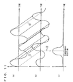
- FIG. 11 shows the waveform of the known reference signal stored in the memory of the CS.
- FIG. 11 shows the waveform of the signal continuously received in the CS from the PS.
- the waveform of the received signal (b) on the time axis matches with the fixed waveform of the reference signal (a) in sections specified by broken lines 1 ⁇ and 2 ⁇ . Therefore, it follows that the correlation value of the waveforms peaks on a time position (shown by a broken line 3 ⁇ ) implementing such matching of the waveforms, while the correlation value lowers (approaches zero) in other time positions.
- correlation synchronization is premised on that a signal from a single PS is independently received in the CS.
- the CS may receive signals of the same frequency from two PSs in an overlapping manner.
- path division multiple access In path division multiple access (hereinafter abbreviated as PDMA) spatially dividing a single time slot of the same frequency and allocating channels to a plurality of PSs, for example, two signals of the same frequency may arrive at the CS in an overlapping manner.
- PDMA path division multiple access
- the CS may receive a radio wave from another PS connected with a CS in another cell as an unnecessary interference radio wave in a state overlapping with a signal of the same frequency from a desired PS.
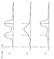
- Fig. 12 is a waveform diagram for illustrating such a state that the synchronous position is hard to specify.
- each of (a) to (c) is a graph showing change (correlation function) of the correlation value between the fixed waveform ((a) in Fig. 11) and received waveforms in the case where two signals of the same frequency are received in the CS in an overlapping manner.
- the conventional method of correlation synchronization has such a problem that the synchronous position of the desired PS cannot be specified when the CS receives two signals of the same frequency in an overlapping manner.
- an object of the present invention is to provide a radio receiving system and a synchronization detection method capable of detecting the synchronous position of a signal received from a desired PS and correctly extracting the received signal by a method of correlation synchronization even when a CS receives signals of the same frequency in an overlapping manner.
- the present invention provides a radio receiving system receiving a signal from a mobile terminal unit with a plurality of antennas, comprising first interference removal means provisionally removing an interference signal component from the received signal, correlation synchronization detection means detecting correlation synchronization of the received signal subjected to removal of the interference signal component by the first interference removal means, and second interference removal means removing an interference signal component from the received signal with the synchronous position detected by the correlation synchronization detection means as a start position.
- a radio receiving system receiving a signal from a mobile terminal unit with a plurality of antennas comprises weight vector calculation means calculating a weight vector corresponding to a desired mobile terminal unit every frame of the received signal, storage means storing the calculated weight vector, first signal extraction means applying the weight vector of a precedent frame stored in the storage means to a frame of a newly received signal and extracting a signal from the desired mobile terminal unit, correlation function calculation means calculating a correlation function of the extracted signal and a prescribed reference signal, synchronous position detection means detecting a time position where the correlation function peaks as a synchronous position, and second signal extraction means applying the weight vector of the frame of the newly received signal calculated by the weight vector calculation means to the frame of the newly received signal for extracting and outputting the signal from the desired mobile terminal unit, while the weight vector calculation means calculates the weight vector of the frame of the newly received signal with the detected synchronous position as a start position.
- a radio receiving system receiving a signal from a mobile terminal unit with a plurality of antennas comprises weight vector calculation means calculating a weight vector corresponding to a desired mobile terminal unit every frame of the received signal, first storage means storing the calculated weight vector, mode set means setting a synchronization capture mode or a synchronization protection mode, first signal extraction means applying said weight vector of a precedent frame stored in the first storage means to a frame of a newly received signal and extracting a signal from the desired mobile terminal unit in the synchronization capture mode, correlation function calculation means calculating a correlation function of the signal extracted by the first signal extraction means and a prescribed reference signal in the synchronization capture mode, synchronous position detection means detecting a time position where the correlation function peaks as a synchronous position in the synchronization capture mode, second storage means storing the detected synchronous position, second signal extraction means applying the weight vector of the frame of the newly received signal calculated by the weight vector calculation means to the frame of the newly received signal for extracting and outputting the signal from
- a radio receiving system receiving a signal from a mobile terminal unit with a plurality of antennas comprises weight vector calculation means calculating a weight vector corresponding to a desired mobile terminal unit every frame of the received signal, first storage means storing the calculated weight vector, mode set means setting a synchronization capture mode or a synchronization protection mode, first signal extraction means applying a weight vector of a precedent frame stored in the first storage means in the synchronization capture mode or the weight vector of the frame of the newly received signal calculated by the weight vector calculation means in the synchronization protection mode to the frame of the newly received signal and extracting a signal from the desired mobile terminal unit, correlation function calculation means calculating a correlation function of the signal extracted by the first signal extraction means and a prescribed reference signal, synchronous position detection means detecting a time position where the correlation function peaks as a synchronous position, second storage means storing the detected synchronous position, second signal extraction means applying the weight vector of the frame of the newly received signal calculated by the weight vector calculation means to the frame of the
- a synchronization detection method in a radio receiving system receiving a signal from a mobile terminal unit with a plurality of antennas comprises steps of provisionally removing an interference signal component from the received signal, detecting correlation synchronization of the received signal subjected to removal of the interference signal component, and removing an interference signal component from the received signal with the synchronous position detected by the correlation synchronization detection as a start position.
- a synchronization detection method in a radio receiving system receiving a signal from a mobile terminal unit with a plurality of antennas comprises steps of calculating a weight vector corresponding to a desired mobile terminal unit every frame of the received signal, storing the calculated weight vector, applying the stored weight vector of a precedent frame to a frame of the newly received signal and extracting a signal from the desired mobile terminal unit, calculating a correlation function of the extracted signal and a prescribed reference signal, detecting a time position where the correlation function peaks as a synchronous position, and applying the calculated weight vector of the frame of the newly received signal to the frame of the newly received signal for extracting and outputting the signal from the desired mobile terminal unit, while the step of calculating the weight vector performs calculation of the weight vector of the frame of the newly received signal with the detected synchronous position as a start position.
- a synchronization detection method in a radio receiving system receiving a signal from a mobile terminal unit with a plurality of antennas comprises steps of calculating a weight vector corresponding to a desired mobile terminal unit every frame of the received signal, storing the calculated weight vector, setting a synchronization capture mode or a synchronization protection mode, applying the stored weight vector of a precedent frame to a frame of the newly received signal and extracting a signal from the desired mobile terminal unit in the synchronization capture mode, calculating a correlation function of the extracted signal and a prescribed reference signal in the synchronization capture mode, detecting a time position where the correlation function peaks as a synchronous position in the synchronization capture mode, storing the detected synchronous position, applying the calculated weight vector of the frame of the newly received signal to the frame of the newly received signal for extracting and outputting the signal from the desired mobile terminal unit, and determining whether or not the extracted signal has a receiving error, while the step of calculating the weight vector performs calculation of the weight vector
- a synchronization detection method in a radio receiving system receiving a signal from a mobile terminal unit with a plurality of antennas comprises steps of calculating a weight vector corresponding to a desired mobile terminal unit every frame of the received signal, storing the calculated weight vector, setting a synchronization capture mode or a synchronization protection mode, applying the stored weight vector of a precedent frame in the synchronization capture mode or the calculated weight vector of the frame of the newly received signal in the synchronization protection mode to the frame of the newly received signal and extracting a signal from the desired mobile terminal unit, calculating a correlation function of the extracted signal and a prescribed reference signal, detecting a time position where the correlation function peaks as a synchronous position, storing the detected synchronous position, applying the calculated weight vector of the frame of the newly received signal to the frame of the newly received signal for extracting and outputting the signal from the desired mobile terminal unit, and determining whether or not the extracted signal has a receiving error, while the step of calculating the weight vector performs
- the present invention suppresses an interference wave component with an adaptive array in a receiver of a CS thereby extracting a signal received from a desired PS and obtaining a correlation value with reference to a reference signal stored in a memory.
- Fig. 1 is a block diagram schematically showing the hardware structure of the receiver of the CS according to the present invention.
- signals received at n antennas ANT 1 , ⁇ , ANT n are supplied to the receiver 1 of the CS, subjected to amplification, frequency conversion and cutting of unnecessary frequency components in corresponding RF circuits RF 1 , ⁇ , RF n , and thereafter converted to digital signals in corresponding A/D converters AD 1 , ⁇ , AD n .
- Outputs of the A/D converters AD 1 , ⁇ , AD n are supplied to a digital signal processor (hereinafter abbreviated as DSP) 2, which implements each of first to third embodiments described later.
- DSP 2 finally outputs a signal from a desired PS in such a state that synchronization is established and an interference wave component is removed.
- a memory 3 is connected to the DSP 2, to hold various data necessary for processing of the DSP 2 in each embodiment described later.
- the output signal from the DSP 2 is supplied to an external device as an output signal from the receiver 1 of the CS.
- Fig. 2 is a functional block diagram for functionally illustrating processing of a DSP 2 according to a first embodiment of the present invention.
- This block diagram expresses the DSP 2 as a combination of various circuit elements for illustrating the principle of operations implemented by the DSP 2, which executes processing along a flow chart shown in Fig. 3 in a software manner in practice.
- Digital signals from the A/D converters AD 1 , ⁇ , AD n shown in Fig. 1 are supplied to first inputs of multipliers MPA 1 , ⁇ , MPA n forming a first adaptive array (signal extraction means or interference removal means) as well as to first inputs of multipliers MPB 1 , ⁇ , MPB n forming a second adaptive array respectively.
- a weight vector calculator 4 also receives the signals from the A/D converters AD 1 , ⁇ , AD n , and calculates a weight vector thereof. The basic idea of calculation of the weight vector is now described.
- the above coefficients a1, a2, ⁇ , an express that the antennas ANT 1 , ANT 2 , ⁇ , ANT n differ from each other in receiving strength with respect to the signal radio wave from the user A
- the coefficients b1, b2, ⁇ , bn express that the antennas ANT 1 , ANT 2 , ⁇ , ANT n differ from each other in receiving strength with respect to the signal radio wave from the user B.
- Each user is moving, and hence these coefficient change in real time.
- the signals x1(t), x2(t), ⁇ , xn(t) received at the respective antennas are supplied to the first inputs of the multipliers MPB 1 , MPB 2 , ⁇ , MPB n forming the second adaptive array, and a weight vector w 1 , w 2 , ⁇ , w n consisting of weights for the signals received at the respective antennas calculated by the weight vector calculator 4 in real time is applied to second inputs of these multipliers.
- the multiplier MPB 1 outputs w 1 ⁇ (a1A(t) + b1B(t)), the multiplier MPB 2 outputs w 2 ⁇ (a2A(t) + b2B(t)), and the multiplier MPB n outputs w n ⁇ (anA(t) + bnB(t)).
- An adder ADDB adds up the outputs of these MPB 1 , MPB 2 , ⁇ , MPB n , to output: w 1 (a1A(t) + b1B(t)) + w 2 (a2A(t) + b2B(t)) + ⁇ + w n (anA(t) + bnB(t))
- This output is divided into terms related to the signal A(t) and terms related to the signal B(t) as follows: (w 1 a1 + w 2 a2 + ⁇ +w n an)A(t) + (w 1 b1 + w 2 b2 + ⁇ +w n bn)B(t)
- the weight vector calculator 4 calculates the above weights w 1 , w 2 , ⁇ , w n to be capable of identifying the users A and B and extracting only the signal from the PS of the desired user.
- the weight vector calculator 4 regards the coefficients a1, a2, ⁇ , an and b1, b2, ⁇ , bn as constants and calculates the weights w 1 , w 2 , ⁇ , w n so that the coefficients of the signal A(t) are 1 as a whole and the coefficients of the signal B(t) are 0 as a whole, in order to extract only the signal A(t) from the PS of the desired user A.
- This output signal is fed back to the weight vector calculator 4, for updating the weight vector values with reference to a reference signal stored in a memory 3.
- the weight vector w 1 , w 2 , ⁇ , w n of the frame of the received signals newly calculated by the weight vector calculator 4 in the aforementioned manner is expressed as w 1NEW , w 2NEW , ⁇ , w nNEW .
- the weight vector newly calculated by the weight vector calculator 4 is supplied to the multiplies MPB 1 , MPB 2 , ⁇ , MPB n of the second adaptive array as described above, and stored in the memory 3.
- the weight vector w 1 , w 2 , ⁇ , w n of precedent frame stored in the memory 3 is expressed as w 1OLD , w 2OLD , ⁇ , w nOLD , to be distinguished from the aforementioned just calculated weight vector.
- the signals received at the antennas ANT 1 , ANT 2 , ⁇ , ANT n are input to the first inputs of the multiplies MPA 1 , MPA 2 , ⁇ , MPA n forming the first adaptive array respectively, and the weight vector w 1OLD , w 2OLD , ⁇ , w nOLD of the precedent frame stored in the memory 3 is input to second inputs of these multipliers.
- This principle is based on such prediction that the directions of arrival of the signal radio waves from the PSs of the users may not abruptly change in a single frame period of 5 milliseconds, noting that the undesired signal component (interference wave component) can be sufficiently removed also when applying the weight vector of the precedent frame to the newly received signals.
- an adder ADDA forming the first adaptive array synthesizes a signal Sy(t) for correlation synchronization subjected to removal of the interference component from the PS of the undesired user, and supplies the same to a correlator 5.
- the correlator 5 calculates the correlation function of the signal Sy(t) subjected to removal of the interference wave and the reference signal (preamble + unique word) stored in the memory 3 as described above with reference to Fig. 11, and supplies the correlation function to a peak detector 6.
- the peak detector 6 detects a time position where the correlation function calculated in the correlator 5 peaks as a synchronous position Sync, and supplies this synchronous position information to the weight vector calculator 4.
- the weight vector calculator 4 regards the synchronous position Sync detected by the peak detector 6 as a start position (SS) of the frame of the received signal and starts calculating the weight vector w 1NEW , w 2NEW , ⁇ , w nNEW .
- the second adaptive array synthesizes the weight vector w 1NEW , w 2NEW , ⁇ , w nNEW calculated in this manner with the frame of the received signal, so that the signal y(t) from the desired PS can be extracted in higher precision.
- Fig. 3 is a flow chart showing processing of the DSP 2 executing the operations of the functional block diagram shown in Fig. 2 by software.
- the multiplies MPA 1 , MPA 2 , ⁇ , MPA n of the aforementioned first adaptive array multiply the received signals x1(t), x2(t), ⁇ , xn(t) by the weight vector w 1OLD , w 2OLD , ⁇ , w nOLD calculated in the precedent frame and stored in the memory 3, so that the adder ADDA synthesizes the total sum as the correlation synchronization signal Sy(t) (in the equation of the step S1, symbol * represents a conjugate complex number).
- the aforementioned correlator 5 calculates the correlation function of the correlation synchronization signal Sy(t) and the reference signal stored in the memory 3, so that the peak position thereof is detected as the synchronous position Sync by an operation corresponding to that of the aforementioned peak detector 6.
- the weight vector w 1NEW , w 2NEW , ⁇ , w nNEW is calculated by an operation corresponding to that of the aforementioned weight vector calculator 4 with the received signals x(t) and the reference signal stored in the memory 3, so that the received signals x1(t), x2(t), ⁇ , xn(t) are multiplied by the calculated weight vector w 1NEW , w 2NEW , ⁇ , w nNEW by an operation corresponding to that of the aforementioned second adaptive array.
- the synthesized total sum is output as the signal y(t) from the desired PS.
- weight vector is not yet calculated and hence weight vector calculation is performed by provisionally setting either one (for example, the higher peak) of the two peaks shown at (a) in Fig. 12 as the synchronous position, for continuing the operations of the aforementioned steps S1 to S3 if there are no receiving errors.
- the start position (SS) of the precedently connected PS is known and hence the processing may be started by setting the other peak position as the start position (SS) of the signal from the PS requiring connection.
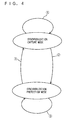
- Fig. 4 is a schematic diagram for conceptually illustrating transition of modes in a second embodiment of the present invention described below and a third embodiment described later.
- an operation mode for establishing synchronization by detecting a synchronous position, not yet detected, of a received signal by the method of correlation synchronization is referred to as a "synchronization capture mode", and an operation mode for maintaining the once established synchronization unless receiving errors are continuously caused is referred to as a "synchronization protection mode”. Detailed operations of the respective modes are described later.
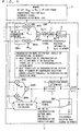
- Fig. 5 is a functional block diagram for functionally illustrating processing of a DSP 2 according to the second embodiment of the present invention.
- This block diagram expresses the DSP 2 as a combination of various circuit elements for illustrating the principle of operations implemented by the DSP similarly to Fig. 2, and the DSP 2 implements processing along flow charts shown in Figs. 6 and 7 by software in practice.
- switches SWA 1 , ⁇ , SWA n are turned on so that a first adaptive array synthesizes received signals x1(t) ⁇ , xn(t) and weight vector w 1OLD , w 2OLD , ⁇ , w nOLD of precedent frame stored in a memory 3 and a signal Sy(t) subjected to removal of an interference wave component is extracted and supplied to a correlator 5, similarly to the aforementioned first embodiment.
- the correlator 5 calculates the correlation function of the signal Sy(t) and a reference signal stored in the memory 3, and supplies the correlation function to a peak detector 6.
- the peak detector 6 detects a time position where the correlation function calculated in the correlator 5 peaks as a synchronous position Sync, and supplies the synchronous position Sync to a weight vector calculator 4 through a switch SWB turned on toward a fixed end SW1 while storing the same in the memory 3 in the synchronization capture mode.
- the weight vector calculator 4 regards the detected synchronous position Sync as the start position (SS) of frame of the received signals, and starts calculating weight vector w 1NEW , w 2NEW , ⁇ , w nNEW .
- a second adaptive array synthesizes the weight vectors w 1NEW , w 2NEW , ⁇ , w nNEW calculated in this manner with the received signals x1(t), ⁇ , xn(t), so that a signal from a desired PS is extracted and output as an output signal y(t) through a detector 7.
- the output signal y(t) from the detector 7 is on one hand supplied to a receiving error determiner 8, which determines presence/absence of receiving errors.
- the result of determination of the receiving error determiner 8 is supplied to a synchronization mode determiner 9.
- the synchronization mode determiner 9 decides transition from the synchronization capture mode to the synchronization protection mode (arrow 2 ⁇ in Fig. 4), and stores a synchronization mode flag indicating the result in the memory 3.
- the receiving error determiner 8 determines that there are receiving errors
- the synchronization capture mode is maintained (arrow 1 ⁇ in Fig. 4), and the aforementioned operations are repeated until the receiving error determiner 8 determines that there are no receiving errors.
- the switches SWA 1 , ⁇ , SWA n are turned off to perform no synchronization preprocessing employing weight vector of the precedent frame.
- a fixed end SW2 of the switch SWB is turned on so that the synchronous position Sync detected in the synchronization capture mode and stored in the memory 3 is supplied to the weight vector calculator 4 as the start position (SS) of the frame of the received signals.
- the weight vector calculator 4 calculates weight vector on the basis of the fixed synchronous position Sync stored in the memory 3 in the synchronization protection mode. This is an operation based on the premise that the synchronous position does not fluctuate at a high speed every frame of a 5 millisecond unit.
- the synchronization mode determiner 9 When receiving errors are detected in the output signal y(t) obtained by the weight vector calculation based on the fixed synchronous position Sync, the synchronization mode determiner 9 maintains the synchronization protection mode unless the number of continuously caused receiving errors exceeds a threshold (arrow 3 ⁇ in Fig. 4).
- the synchronization mode determiner 9 decides transition from the synchronization protection mode to the synchronization capture mode (arrow 4 ⁇ in Fig. 4), and stores a synchronization mode flag indicating the result in the memory 3.
- the aforementioned synchronization preprocessing employing the first adaptive array and the weight vector of the precedent frame is executed for detecting the synchronous position by correlation synchronization again.
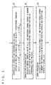
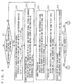
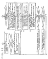
- Figs. 6 and 7 are flow charts showing the operations of the functional block diagram shown in Fig. 5 executed by the DSP 2 by software as a whole.
- synchronization mode determination is executed for determining whether the DSP 2 is in the synchronization capture mode or in the synchronization protection mode at present.
- the signal y(t) is extracted at the step S14, the signal y(t) is detected by an operation corresponding to that of the detector 7 shown in Fig. 5 at a step S15, and it is determined whether or not the aforementioned detected demodulated output has receiving errors at a step S16 by an operation corresponding to that of the receiving error determiner 8 shown in Fig. 5.
- transition from the synchronization capture mode to the synchronization protection mode is executed at a step S18 (arrow 2 ⁇ in Fig. 4).
- step S17 When it is determined that there are receiving errors at the step S17, on the other hand, the number of continuous errors is counted at a step S19, so that the synchronization capture mode is maintained as such (arrow 1 ⁇ in Fig. 4) even if the count is 1 (step S20).
- the synchronization preprocessing and the detection of the synchronous position by correlation synchronization at the steps S12 and S13 are skipped for immediately executing array processing at the step S14.
- calculation of weight vector is executed with the synchronous position Sync detected in the precedent synchronization capture mode stored in the memory 3 as a start position (SS).
- the synchronization protection mode is maintained at a step S18 (arrow 3 ⁇ in Fig. 4).
- step S17 When it is determined that there are receiving errors at the step S17, on the other hand, continuous errors are counted at a step S19 so that transition from the synchronization protection mode to the synchronization capture mode is executed at a step S21 if the count exceeds the threshold value at a step S20 (arrow 4 ⁇ in Fig. 4).
- a continuous error counter is initialized to zero at the step S18.
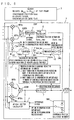
- Fig. 8 is a functional block diagram for functionally illustrating processing of a DSP 2 according to the third embodiment of the present invention.
- This block diagram expresses the DSP 2 as a combination of various circuit elements for illustrating the principle of operations implemented by the DSP 2 similarly to Figs. 2 and 5, and the DSP 2 implements processing along flow charts shown in Figs. 9 and 10 by software in practice.
- the correlator 5 calculates the correlation function of the signal Sy(t) and a reference signal stored in the memory 3, and supplies the correlation function to a peak detector 6.
- the peak detector 6 detects a time position where the correlation function calculated in the correlator 5 peaks as a synchronous position Sync, and supplies the synchronous position Sync to a weight vector calculator 4 through a switch SWB turned on toward a fixed end SW1 while storing the same in the memory 3 in the synchronization capture mode.
- the weight vector calculator 4 regards the detected synchronous position Sync as the start position (SS) of the frame of the received signals and starts calculating weight vector w 1NEW, w 2NEW, ⁇ , w nNEW .
- a second adaptive array synthesizes the weight vector w 1NEW , w 2NEW , ⁇ , w nNEW calculated in this manner with the received signals x1(t), ⁇ , xn(t), so that a signal from a desired PS is extracted and output as an output signal y(t) through a detector 7.
- the output signal y(t) from the detector 7 is supplied to a receiving error determiner 8 on one hand, so that presence/absence of receiving errors is determined.
- the result of the determination of the receiving error determiner 8 is supplied to a synchronization mode determiner 9.
- the synchronization mode determiner 9 decides transition from the synchronization capture mode to a synchronization protection mode (arrow 2 ⁇ in Fig. 4), and stores a synchronization mode flag indicating the result in the memory 3.
- the receiving error determiner 8 determines that there are receiving errors
- the synchronization capture mode is maintained (arrow 1 ⁇ in Fig. 4) and the aforementioned operations are repeated until it is determined that there are no receiving errors.
- the switch SWB is turned on toward a fixed end SW2, so that the synchronous position Sync detected in the synchronization capture mode and stored in the memory 3 is supplied to the weight vector calculator 4 as the start position of the frame of the received signals. Thereafter the weight vector calculator 4 calculates a weight vector on the basis of the synchronous position Sync stored in the memory 3.
- the synchronization protection mode is maintained unless the number of continuously caused receiving errors exceeds a threshold (arrow 3 ⁇ in Fig. 4).
- the synchronization mode determiner 9 decides transition from the synchronization protection mode to the synchronization capture mode (arrow 4 ⁇ in Fig. 4), and stores a synchronization mode flag indicating the result in the memory 3.
- the aforementioned synchronization preprocessing employing the first adaptive array and the weight vector of the precedent frame is executed for detecting the synchronous position again.
- the synchronous position Sync stored in the memory 3 remains fixed during the synchronization protection mode period in the second embodiment, the synchronous position Sync stored in the memory 3 is finely controlled in the third embodiment also in the synchronization protection mode period, as described below.
- the correlator 5 calculates the correlation function of the signal Sy(t) and the reference signal stored in the memory 3 and supplies the correlation function to the peak detector 6.
- the peak detector 6 detects a time position where the correlation function calculated in the calculator 5 peaks as synchronous position information Sync_tmp, which in turn is supplied to a first input of a comparator 10 through a switch SWC turned on in the synchronization protection mode.
- the synchronous position Sync stored in the memory 3 is input in a second input of the comparator 10.
- the comparator 10 increments the count of a counter 11 by 1 when the synchronous position information Sync_tmp is greater than the synchronous position Sync (Sync_tmp > Sync), and decrements the count by 1 when the synchronous position information Sync_tmp is less than the synchronous position Sync (Sync_tmp ⁇ Sync).
- the count of the counter 11 is supplied to a synchronization follower 12, so that the synchronous position Sync stored in the memory 3 is updated in a positive direction when the count of the counter 11 positively increases to exceed a first threshold while the synchronous position Sync stored in the memory 3 is updated in a negative direction when the count negatively reduces below a second threshold.
- the received signals can be demodulated in higher precision by finely controlling the synchronous position information stored in the memory in a direction where the synchronous position deviates in consideration of that the actual synchronous position can finely fluctuate also in the synchronization protection mode period.
- Figs. 9 and 10 are flow charts showing processing of the DSP 2 implementing the operations of the functional block diagram shown in Fig. 8 by software as a whole.
- steps S22 to S29 show processing specific to the third embodiment.
- the correlation function is calculated at the step S23 by an operation corresponding to that of the correlator 5 shown in Fig. 8. Then, the time position where the correlation function peaks is detected as the synchronous position information Sync_tmp by an operation corresponding to that of the peak detector 6 shown in Fig. 8.
- the synchronous position Sync stored in the memory 3 is compared with the aforementioned synchronous position information Sync_tmp, for decrementing the count of the counter by 1 if the synchronous position information Sync_tmp is less than the synchronous position Sync (Sync_tmp ⁇ Sync), while incrementing the count of the counter by 1 if the synchronous position information Sync_tmp is greater than the synchronous position Sync (Sync_tmp > Sync).
- the synchronous position Sync stored in the memory is updated by +1 at the step S27.
- the synchronous position Sync stored in the memory is updated by -1 at the step S29.
- the synchronous position is specified by the method of correlation synchronization after removing the interference wave component by synchronization preprocessing even when signals of the same frequency are received in the CS in an overlapping manner, whereby the synchronous position of a signal received from a desired PS can be correctly detected to be subjected to precise demodulation.
- the radio receiving system and the synchronization detection method according to the present invention are suitable for detecting the synchronous position of a signal received from a mobile terminal unit in a base station of a mobile communication system of the PDMA system, for example.
Landscapes
- Engineering & Computer Science (AREA)
- Computer Networks & Wireless Communication (AREA)
- Signal Processing (AREA)
- Synchronisation In Digital Transmission Systems (AREA)
- Mobile Radio Communication Systems (AREA)
- Digital Transmission Methods That Use Modulated Carrier Waves (AREA)
- Radio Transmission System (AREA)
Abstract
Description
Claims (8)
- A radio receiving system (1) receiving a signal from a mobile terminal unit with a plurality of antennas (ANT1, ···. ANTn), comprising:first interference removal means (MPA1, ···, MPAn, ADDA, 4) provisionally removing an interference signal component from received said signal;correlation synchronization detection means (5, 6) detecting correlation synchronization of said received signal subjected to removal of the interference signal component by said first interference removal means; andsecond interference removal means (MPB1, ···, MPBn, ADDB, 4) removing an interference signal component from said received signal with a synchronous position detected by said correlation synchronization detection means as a start position.
- A radio receiving system (1) receiving a signal from a mobile terminal unit with a plurality of antennas (ANT1, ···. ANTn), comprising:said weight vector calculation means calculates the weight vector of the frame of said newly received signal with said detected synchronous position as a start position.weight vector calculation means (4) calculating a weight vector corresponding to a desired mobile terminal unit every frame of received said signal;storage means (3) storing said calculated weight vector;first signal extraction means (MPA1, ···, MPAn, ADDA) applying said weight vector of a precedent frame stored in said storage means to a frame of newly received said signal and extracting a signal from said desired mobile terminal unit;correlation function calculation means (5) calculating a correlation function of said extracted signal and a prescribed reference signal;synchronous position detection means (6) detecting a time position where said correlation function peaks as a synchronous position; andsecond signal extraction means (MPB1, ···, MPBn, ADDB) applying the weight vector of the frame of said newly received signal calculated by said weight vector calculation means to the frame of said newly received signal for extracting and outputting the signal from said desired, mobile terminal unit, wherein
- A radio receiving system (1) receiving a signal from a mobile terminal unit with a plurality of antennas (ANT1, ···. ANTn), comprising:said weight vector calculation means calculates the weight vector of the frame of said newly received signal with the synchronous position detected by said synchronous position detection means as a start position in said synchronization capture mode or with the synchronous position stored in said second storage means as a start position in said synchronization protection mode, andweight vector calculation means (4) calculating a weight vector corresponding to a desired mobile terminal unit every frame of received said signal;first storage means (3) storing said calculated weight vector;mode set means (9) setting a synchronization capture mode or a synchronization protection mode;first signal extraction means (MPA1, ···, MPAn, ADDA) applying said weight vector of a precedent frame stored in said first storage means to a frame of newly received said signal and extracting a signal from said desired mobile terminal unit in said synchronization capture mode;correlation function calculation means (5) calculating a correlation function of the signal extracted by said first signal extraction means and a prescribed reference signal in said synchronization capture mode;synchronous position detection means (6) detecting a time position where said correlation function peaks as a synchronous position in said synchronization capture mode;second storage means (3) storing said detected synchronous position;second signal extraction means (MPB1, ···, MPBn, ADDB) applying the weight vector of the frame of said newly received signal calculated by said weight vector calculation means to the frame of said newly received signal for extracting and outputting the signal from said desired mobile terminal unit; anderror determination means (8) determining whether or not the signal extracted by said second signal extraction means has a receiving error, wherein
said mode set means sets said synchronization protection mode when said error determination means determines that there is no error in said synchronization capture mode while maintaining said synchronization capture mode when said error determination means determines that there is an error in said synchronization capture mode and sets said synchronization capture mode when said error determination means continuously determines that there is an error in excess of a prescribed number of times in said synchronization protection mode while maintaining said synchronization protection mode when said prescribed number of times is not reached in said synchronization protection mode. - A radio receiving system (1) receiving a signal from a mobile terminal unit with a plurality of antennas (ANT1, ···. ANTn), comprising:said weight vector calculation means calculates the weight vector of the frame of said newly received signal with the synchronous position detected by said synchronous position detection means as a start position in said synchronization capture mode or with the synchronous position stored in said second storage means as a start position in said synchronization protection mode, andweight vector calculation means (4) calculating a weight vector corresponding to a desired mobile terminal unit every frame of received said signal;first storage means (3) storing said calculated weight vector;mode set means (9) setting a synchronization capture mode or a synchronization protection mode;first signal extraction means (MPA1, ···, MPAn, ADDA) applying said weight vector of a precedent frame stored in said first storage means in said synchronization capture mode or the weight vector of the frame of newly received said signal calculated by said weight vector calculation means in said synchronization protection mode to the frame of said newly received signal and extracting a signal from said desired mobile terminal unit;correlation function calculation means (5) calculating a correlation function of the signal extracted by said first signal extraction means and a prescribed reference signal;synchronous position detection means (6) detecting a time position where said correlation function peaks as a synchronous position;second storage means (3) storing said detected synchronous position;second signal extraction means (MPB1, ···, MPBn, ADDB) applying the weight vector of the frame of said newly received signal calculated by said weight vector calculation means to the frame of said newly received signal for extracting and outputting the signal from said desired mobile terminal unit; anderror determination means (8) determining whether or not the signal extracted by said second signal extraction means has a receiving error, wherein
said mode set means sets said synchronization protection mode when said error determination means determines that there is no error in said synchronization capture mode while maintaining said synchronization capture mode when said error determination means determines that there is an error in said synchronization capture mode and sets said synchronization capture mode when said error determination means continuously determines that there is an error in excess of a prescribed number of times in said synchronization protection mode while maintaining said synchronization protection mode when said prescribed number of times is not reached in said synchronization protection mode,
said radio receiving-system-further comprising means (12) comparing the synchronous position detected by said synchronous position detection means with the synchronous position stored in said second storage means in said synchronization protection mode for updating the synchronous position stored in said second storage means when the difference between the synchronous positions exceeds a prescribed magnitude. - A synchronization detection method in a radio receiving system (1) receiving a signal from a mobile terminal unit with a plurality of antennas (ANT1, ···. ANTn), comprising steps of:provisionally an interference signal component from received said signal;detecting correlation synchronization of said received signal subjected to removal of the interference signal component; andremoving an interference signal component from said received signal with the synchronous position detected by said correlation synchronization detection as a start position.
- A synchronization detection method in a radio receiving system (1) receiving a signal from a mobile terminal unit with a plurality of antennas (ANT1, ···. ANTn), comprising steps of:said step of calculating said weight vector performs calculation of the weight vector of the frame of said newly received signal with said detected synchronous position as a start position.calculating a weight vector corresponding to a desired mobile terminal unit every frame of received said signal;storing said calculated weight vector;applying said stored weight vector of a precedent frame to a frame of newly received said signal and extracting a signal from said desired mobile terminal unit;calculating a correlation function of said extracted signal and a prescribed reference signal;detecting a time position where said correlation function peaks as a synchronous position; andapplying the calculated weight vector of the frame of said newly received signal to the frame of said newly received signal for extracting and outputting the signal from said desired mobile terminal unit, wherein
- A synchronization detection method in a radio receiving system (1) receiving a signal from a mobile terminal unit with a plurality of antennas (ANT1, ···. ANTn), comprising steps of:said step of calculating said weight vector performs calculation of the weight vector of the frame of said newly received signal with said detected synchronous position as a start position in said synchronization capture mode or with said stored synchronous position as a start position in said synchronization protection mode, andcalculating a weight vector corresponding to a desired mobile terminal unit every frame of received said signal;storing said calculated weight vector;setting a synchronization capture mode or a synchronization protection mode;applying said stored weight vector of a precedent frame to a frame of newly received said signal and extracting a signal from said desired mobile terminal unit in said synchronization capture mode;calculating a correlation function of said extracted signal and a prescribed reference signal in said synchronization capture mode;detecting a time position where said correlation function peaks as a synchronous position in said synchronization capture mode;storing said detected synchronous position;applying the calculated weight vector of the frame of said newly received signal to the frame of said newly received signal for extracting and outputting the signal from said desired mobile terminal unit; anddetermining whether or not said extracted signal has a receiving error, wherein
said step of setting said mode sets said synchronization protection mode when it is determined that there is no error in said synchronization capture mode while maintaining said synchronization capture mode when it is determined that there is an error in said capture mode and sets said synchronization capture mode when it is continuously determined that there is an error in excess of a prescribed number of times in said synchronization protection mode while maintaining said synchronization protection mode when said prescribed number of times is not reached in said synchronization protection mode. - A synchronization detection method in a radio receiving system (1) receiving a signal from a mobile terminal unit with a plurality of antennas (ANT1, ···. ANTn), comprising steps of:said step of calculating said weight vector performs calculation of the weight vector of the frame of said newly received signal with said detected synchronous position as a start position in said synchronization capture mode or with said stored synchronous position as a start position in said synchronization protection mode, andcalculating a weight vector corresponding to a desired mobile terminal unit every frame of received said signal;storing said calculated weight vector;setting a synchronization capture mode or a synchronization protection mode;applying said stored weight vector of a precedent frame in said synchronization capture mode or said calculated weight vector of the frame of newly received said signal in said synchronization protection mode to the frame of said newly said signal and extracting a signal from said desired mobile terminal unit;calculating a correlation function of said extracted signal and a prescribed reference signal;detecting a time position where said correlation function peaks as a synchronous position;storing said detected synchronous position;applying the calculated weight vector of the frame of said newly received signal to the frame of said newly received signal for extracting and outputting the signal from said desired mobile terminal unit; anddetermining whether or not said extracted signal has a receiving error, wherein
said step of setting said mode sets said synchronization protection mode when it is determined that there is no error in said synchronization capture mode while maintaining said synchronization capture mode when it is determined that there is an error in said synchronization capture mode and sets said synchronization capture mode when it is continuously determined that there is an error in excess of a prescribed number of times in said synchronization protection mode while maintaining said synchronization protection mode when said prescribed number of times is not reached in said synchronization protection mode,
said synchronization detection method further comprising a step of comparing said detected synchronous position with said stored synchronous position in said synchronization protection mode for updating said stored synchronous position when the difference between the synchronous positions exceeds a prescribed magnitude.
Applications Claiming Priority (3)
| Application Number | Priority Date | Filing Date | Title |
|---|---|---|---|
| JP31686199 | 1999-11-08 | ||
| JP31686199 | 1999-11-08 | ||
| PCT/JP2000/007487 WO2001035590A1 (en) | 1999-11-08 | 2000-10-25 | Radio receiving system and synchronization detection method |
Publications (3)
| Publication Number | Publication Date |
|---|---|
| EP1227631A1 true EP1227631A1 (en) | 2002-07-31 |
| EP1227631A4 EP1227631A4 (en) | 2006-02-01 |
| EP1227631B1 EP1227631B1 (en) | 2008-07-23 |
Family
ID=18081742
Family Applications (1)
| Application Number | Title | Priority Date | Filing Date |
|---|---|---|---|
| EP00970085A Expired - Lifetime EP1227631B1 (en) | 1999-11-08 | 2000-10-25 | Radio receiving system and synchronization detection method |
Country Status (9)
| Country | Link |
|---|---|
| US (1) | US7076212B1 (en) |
| EP (1) | EP1227631B1 (en) |
| JP (1) | JP3500141B2 (en) |
| KR (1) | KR100491905B1 (en) |
| CN (1) | CN100423521C (en) |
| AU (1) | AU763010B2 (en) |
| DE (1) | DE60039620D1 (en) |
| TW (1) | TW471225B (en) |
| WO (1) | WO2001035590A1 (en) |
Cited By (1)
| Publication number | Priority date | Publication date | Assignee | Title |
|---|---|---|---|---|
| KR101443799B1 (en) * | 2012-03-30 | 2014-09-23 | 브로드콤 코포레이션 | Mobile device searching using multiple antennas |
Families Citing this family (6)
| Publication number | Priority date | Publication date | Assignee | Title |
|---|---|---|---|---|
| JP4728597B2 (en) * | 2004-06-09 | 2011-07-20 | 日本無線株式会社 | Array antenna communication device |
| FR2882479B1 (en) * | 2005-02-22 | 2007-04-20 | Thales Sa | METHOD AND DEVICE FOR SYNCHRONIZING RECTILIGNED OR QUASI-RECTILINE LINKS IN THE PRESENCE OF INTERFERENCE |
| CN100459455C (en) * | 2005-03-01 | 2009-02-04 | 普天信息技术研究院 | Random access detecting method based on intelligent antenna |
| CN100456653C (en) * | 2005-03-01 | 2009-01-28 | 普天信息技术研究院 | A Synchronization Control Method Based on Smart Antenna |
| US9197470B2 (en) | 2007-10-05 | 2015-11-24 | Innurvation, Inc. | Data transmission via multi-path channels using orthogonal multi-frequency signals with differential phase shift keying modulation |
| KR101924830B1 (en) * | 2012-06-19 | 2019-02-27 | 삼성전자주식회사 | Method and apparatus for synchronizing of terminal in wireless communication network |
Family Cites Families (14)
| Publication number | Priority date | Publication date | Assignee | Title |
|---|---|---|---|---|
| JPS63278434A (en) * | 1987-05-08 | 1988-11-16 | Mitsubishi Electric Corp | Adaptive antenna system for fh communication |
| JP2977837B2 (en) * | 1989-08-09 | 1999-11-15 | 株式会社日立製作所 | Time-division multiplex receiver with adaptive array |
| JPH07154129A (en) * | 1993-11-29 | 1995-06-16 | Nippon Motorola Ltd | LMS type adaptive array antenna device |
| JP2605648B2 (en) * | 1994-12-22 | 1997-04-30 | 日本電気株式会社 | Despreading code phase detector for SS receiver |
| US6137843A (en) * | 1995-02-24 | 2000-10-24 | Ericsson Inc. | Methods and apparatus for canceling adjacent channel signals in digital communications systems |
| JP2728034B2 (en) * | 1995-06-15 | 1998-03-18 | 日本電気株式会社 | Spread spectrum signal receiver |
| US6014570A (en) * | 1995-12-18 | 2000-01-11 | The Board Of Trustees Of The Leland Stanford Junior University | Efficient radio signal diversity combining using a small set of discrete amplitude and phase weights |
| JPH09275364A (en) * | 1996-04-08 | 1997-10-21 | Toyota Autom Loom Works Ltd | Synchronizer for spread spectrum communication |
| JP3272961B2 (en) * | 1996-08-02 | 2002-04-08 | 株式会社日立国際電気 | Adaptive array antenna |
| US6335954B1 (en) * | 1996-12-27 | 2002-01-01 | Ericsson Inc. | Method and apparatus for joint synchronization of multiple receive channels |
| JPH1141141A (en) * | 1997-05-21 | 1999-02-12 | Mitsubishi Electric Corp | Spread spectrum signal receiving method and spread spectrum signal receiving apparatus |
| JP2914445B2 (en) * | 1997-08-05 | 1999-06-28 | 日本電気株式会社 | CDMA adaptive receiver |
| JPH11239086A (en) * | 1998-02-24 | 1999-08-31 | Matsushita Commun Ind Co Ltd | Synchronization method and synchronization device |
| JP3967838B2 (en) * | 1999-01-07 | 2007-08-29 | 富士通株式会社 | Wireless receiver and despreader |
-
2000
- 2000-10-25 EP EP00970085A patent/EP1227631B1/en not_active Expired - Lifetime
- 2000-10-25 DE DE60039620T patent/DE60039620D1/en not_active Expired - Fee Related
- 2000-10-25 CN CNB008168938A patent/CN100423521C/en not_active Expired - Fee Related
- 2000-10-25 JP JP2001537216A patent/JP3500141B2/en not_active Expired - Fee Related
- 2000-10-25 KR KR10-2002-7005903A patent/KR100491905B1/en not_active Expired - Fee Related
- 2000-10-25 AU AU79583/00A patent/AU763010B2/en not_active Ceased
- 2000-10-25 WO PCT/JP2000/007487 patent/WO2001035590A1/en not_active Ceased
- 2000-10-25 US US10/111,414 patent/US7076212B1/en not_active Expired - Lifetime
- 2000-10-27 TW TW089122646A patent/TW471225B/en not_active IP Right Cessation
Cited By (2)
| Publication number | Priority date | Publication date | Assignee | Title |
|---|---|---|---|---|
| KR101443799B1 (en) * | 2012-03-30 | 2014-09-23 | 브로드콤 코포레이션 | Mobile device searching using multiple antennas |
| US9143189B2 (en) | 2012-03-30 | 2015-09-22 | Broadcom Corporation | Mobile device searching using multiple antennas |
Also Published As
| Publication number | Publication date |
|---|---|
| EP1227631A4 (en) | 2006-02-01 |
| US7076212B1 (en) | 2006-07-11 |
| KR100491905B1 (en) | 2005-05-27 |
| WO2001035590A1 (en) | 2001-05-17 |
| AU763010B2 (en) | 2003-07-10 |
| CN100423521C (en) | 2008-10-01 |
| CN1409910A (en) | 2003-04-09 |
| TW471225B (en) | 2002-01-01 |
| DE60039620D1 (en) | 2008-09-04 |
| AU7958300A (en) | 2001-06-06 |
| EP1227631B1 (en) | 2008-07-23 |
| KR20020049033A (en) | 2002-06-24 |
| JP3500141B2 (en) | 2004-02-23 |
Similar Documents
| Publication | Publication Date | Title |
|---|---|---|
| US7471750B2 (en) | Receiving method and receiver | |
| US6671516B1 (en) | Transmission channel allocation method and radio apparatus using the same | |
| JP3505468B2 (en) | Wireless device | |
| JPH11340886A (en) | Wireless communication device and wireless communication method | |
| US7076212B1 (en) | Radio receiving system and synchronization detection method | |
| US20040101073A1 (en) | Method and apparatus for estimating response characteristic, and receiving method and receiver utilizing the same | |
| EP1315235B1 (en) | Adaptive array device, adaptive array method and program | |
| JP2004289407A (en) | Adaptive array wireless device, antenna selecting method, and antenna selecting program | |
| JP3851478B2 (en) | Adaptive array antenna device | |
| JPWO2001035590A1 (en) | Wireless receiving system and synchronous detection method | |
| JP3685697B2 (en) | Wireless reception system and weight update method | |
| JPH1051221A (en) | Adaptive array antenna | |
| KR20010072101A (en) | Receiving device and method of generating replica signal | |
| US6861981B2 (en) | Normalizing apparatus for adaptive beamforming in smart antenna receiving system | |
| EP1416650A1 (en) | Initial synchronization searching in mobile communication systems | |
| US6449268B1 (en) | Digital radio communication system, PDMA radio base station reception system and weight vector calculation method | |
| EP1531556A1 (en) | Data reception device and data reception method | |
| EP1164736A1 (en) | Receiver and method for inferring reception time | |
| JP2003087135A (en) | Wireless reception system, synchronization detection method, and synchronization detection program | |
| EP1434369A2 (en) | Received response characteristics storing method and radio apparatus utilizing the same | |
| KR20000060728A (en) | Rake receiver in cdma adaptive array antenna system | |
| JP2000004193A (en) | Adaptive antenna | |
| EP1566899B1 (en) | Multipath compensation for diversity signal receivers | |
| JP3749202B2 (en) | RADIO RECEIVER, SYNCHRONIZATION POSITION ESTIMATION METHOD, AND SYNCHRONIZATION POSITION ESTIMATION PROGRAM | |
| EP1204221A1 (en) | Radio receiver and radio receiving method |
Legal Events
| Date | Code | Title | Description |
|---|---|---|---|
| PUAI | Public reference made under article 153(3) epc to a published international application that has entered the european phase |
Free format text: ORIGINAL CODE: 0009012 |
|
| 17P | Request for examination filed |
Effective date: 20020507 |
|
| AK | Designated contracting states |
Kind code of ref document: A1 Designated state(s): AT BE CH CY DE DK ES FI FR GB GR IE IT LI LU MC NL PT SE |
|
| AX | Request for extension of the european patent |
Free format text: AL;LT;LV;MK;RO;SI |
|
| RBV | Designated contracting states (corrected) |
Designated state(s): AT BE CH CY DE FI FR GB LI SE |
|
| A4 | Supplementary search report drawn up and despatched |
Effective date: 20051220 |
|
| 17Q | First examination report despatched |
Effective date: 20060508 |
|
| GRAP | Despatch of communication of intention to grant a patent |
Free format text: ORIGINAL CODE: EPIDOSNIGR1 |
|
| RBV | Designated contracting states (corrected) |
Designated state(s): DE FI FR GB SE |
|
| RTI1 | Title (correction) |
Free format text: RADIO RECEIVING SYSTEM AND SYNCHRONIZATION DETECTION METHOD |
|
| GRAS | Grant fee paid |
Free format text: ORIGINAL CODE: EPIDOSNIGR3 |
|
| GRAA | (expected) grant |
Free format text: ORIGINAL CODE: 0009210 |
|
| RIN1 | Information on inventor provided before grant (corrected) |
Inventor name: MIYATA, TAKEOC/O SANYO ELECTRIC CO., LTD. Inventor name: DOI, YOSHIHARUC/O SANYO ELECTRIC CO., LTD. |
|
| AK | Designated contracting states |
Kind code of ref document: B1 Designated state(s): DE FI FR GB SE |
|
| REG | Reference to a national code |
Ref country code: GB Ref legal event code: FG4D |
|
| REF | Corresponds to: |
Ref document number: 60039620 Country of ref document: DE Date of ref document: 20080904 Kind code of ref document: P |
|
| PG25 | Lapsed in a contracting state [announced via postgrant information from national office to epo] |
Ref country code: FI Free format text: LAPSE BECAUSE OF FAILURE TO SUBMIT A TRANSLATION OF THE DESCRIPTION OR TO PAY THE FEE WITHIN THE PRESCRIBED TIME-LIMIT Effective date: 20080723 |
|
| PLBE | No opposition filed within time limit |
Free format text: ORIGINAL CODE: 0009261 |
|
| STAA | Information on the status of an ep patent application or granted ep patent |
Free format text: STATUS: NO OPPOSITION FILED WITHIN TIME LIMIT |
|
| PGFP | Annual fee paid to national office [announced via postgrant information from national office to epo] |
Ref country code: GB Payment date: 20081024 Year of fee payment: 9 |
|
| 26N | No opposition filed |
Effective date: 20090424 |
|
| REG | Reference to a national code |
Ref country code: FR Ref legal event code: ST Effective date: 20090630 |
|
| PG25 | Lapsed in a contracting state [announced via postgrant information from national office to epo] |
Ref country code: DE Free format text: LAPSE BECAUSE OF NON-PAYMENT OF DUE FEES Effective date: 20090501 |
|
| PG25 | Lapsed in a contracting state [announced via postgrant information from national office to epo] |
Ref country code: FR Free format text: LAPSE BECAUSE OF NON-PAYMENT OF DUE FEES Effective date: 20081031 |
|
| PG25 | Lapsed in a contracting state [announced via postgrant information from national office to epo] |
Ref country code: SE Free format text: LAPSE BECAUSE OF FAILURE TO SUBMIT A TRANSLATION OF THE DESCRIPTION OR TO PAY THE FEE WITHIN THE PRESCRIBED TIME-LIMIT Effective date: 20081023 |
|
| PG25 | Lapsed in a contracting state [announced via postgrant information from national office to epo] |
Ref country code: GB Free format text: LAPSE BECAUSE OF NON-PAYMENT OF DUE FEES Effective date: 20091025 |