EP1227573A2 - Optimized flap actuator control of a vehicle air conditioner - Google Patents
Optimized flap actuator control of a vehicle air conditioner Download PDFInfo
- Publication number
- EP1227573A2 EP1227573A2 EP02001321A EP02001321A EP1227573A2 EP 1227573 A2 EP1227573 A2 EP 1227573A2 EP 02001321 A EP02001321 A EP 02001321A EP 02001321 A EP02001321 A EP 02001321A EP 1227573 A2 EP1227573 A2 EP 1227573A2
- Authority
- EP
- European Patent Office
- Prior art keywords
- frequency
- motor
- torque
- response
- shutter
- Prior art date
- Legal status (The legal status is an assumption and is not a legal conclusion. Google has not performed a legal analysis and makes no representation as to the accuracy of the status listed.)
- Granted
Links
Images

Classifications
-
- H—ELECTRICITY
- H02—GENERATION; CONVERSION OR DISTRIBUTION OF ELECTRIC POWER
- H02P—CONTROL OR REGULATION OF ELECTRIC MOTORS, ELECTRIC GENERATORS OR DYNAMO-ELECTRIC CONVERTERS; CONTROLLING TRANSFORMERS, REACTORS OR CHOKE COILS
- H02P8/00—Arrangements for controlling dynamo-electric motors of the kind having motors rotating step by step
- H02P8/14—Arrangements for controlling speed or speed and torque
Definitions
- the invention relates to distribution flap actuators or air mixing or recirculation (air intake) in the installations motor vehicle air conditioning.
- the shutters are moved by geared motors in response to actuation orders produced by a central control unit according to the needs to be satisfied such as ventilation start or stop, room temperature adjustment, demisting, defrosting, ...
- the motors of the geared motors generally stepper motors are chosen to deliver the power needed to drive the flaps at maximum speed in all circumstances, i.e. whatever the fluctuations in the supply voltage and the couple needs. Couples needs are variable not only depending on the technology of the shutters and the nature of their drive kinematics, but also depending on conditions instantaneous such as ventilation power, exerted back pressure on the shutter and opposing the desired movement, temperature, ...
- the gearmotors used in the installations of known air conditioning systems are then oversized in power to satisfy the couple's needs.
- the invention aims to allow the use of lower power gearmotors than those used usual today, in order to lower the costs of the installation of air conditioning, but while satisfying the couple's needs and without significantly penalize the speed of execution of orders actuating.
- the adaptation of the control frequency can be carried out by continuously collecting information representing the need for torque delivered by the motor to move the flap, decreasing, if necessary the frequency of piloting in response to an increase torque requirement detected, and when the control frequency is lower than a predetermined maximum frequency, by increasing, the if applicable, the frequency of piloting in response to a decrease detected the need for a couple.
- the variation of the control frequency can be carried out from almost continuously according to the fluctuations in the torque requirement detected, or in stages, the passage from one level to another being controlled in response to the crossing of a threshold by the torque requirement detected.
- the process according to the invention optimizes the use of the available power.
- An oversizing of the power as it would be necessary for satisfying peaks in torque requirements during transitional periods during the shutter displacement phase, becomes unnecessary. These periods possible transients rarely represent more than 20% of the time total actuation of the flaps, so that the engine slows down during these possible transitional periods does not significantly affect the total duration of the actuation.
- the actuation time remaining reduced it is possible without risk of overheating from operating the stepper motor overpowered, by applying a supply voltage corresponding to an overpowered operating mode. As safety, we can then order the engine to stop if a temperature heating limit is exceeded.
- the detection of the torque requirement delivered by the engine can be carried out by measuring a quantity directly or indirectly representative of the torque such as voltage measurement on a phase of the motor, measuring current in a motor winding or measuring instantaneous engine rotation speed, deceleration below of a certain limit reflecting in the latter case the crossing of a torque value threshold for the control frequency used.
- the invention also aims to provide an actuator allowing the implementation of the process defined above.
- the invention also relates to an air conditioning installation vehicle comprising at least one actuator.
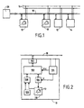
- a automotive air conditioning system includes conventionally a plurality of actuators 10 (of which only two are shown in the figure) to control the movement of air distribution and mixing in order to achieve desired functions of ventilation, cabin temperature adjustment, demisting, defrosting, ... controlled from a control panel 12.
- the actuators 10 as well as the control panel 12 and temperature probes 14 are connected to an energy bus 16 carrying the vehicle battery voltage or a voltage derived from this, and an information link 18.
- the link 18 is advantageously constituted by an information bus.
- Bus 18 is connected to a central control unit 20. This receives status information from control panel 12, probes 14 and actuators 10, such as flap position information and transmits order information, including orders actuating flaps by addressing the actuators 10, these having each a specific address.
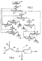
- each actuator 10 comprises a microprocessor-based control unit 100 connected to the information bus 18 by a bus interface 102.
- An electrical supply circuit 104 connected to the energy bus 16 comprises filtering, protection and voltage regulation circuits for supplying a logic supply voltage V cc to the control unit 100 and a motor supply voltage V to an analog interface circuit 106.
- a gearmotor 110 coupled to a air distribution or mixing shutter (not shown) comprises a stepping motor 112 which receives from the circuit 106 the voltage V in the form of pulse trains applied to the phases of the motor at a determined pilot frequency, under the control of the unit 100 to which the interface 106 is connected.
- a data interface 108 is connected to the gearmotor 110 and to the control unit 100 in order to transmit to the latter state data, in particular shutter position data, for example indicating the arrival of the shutter at the end of its travel. .
- the actuator 10 further comprises a circuit 120 providing information representative of the need for torque delivered by the stepping motor 112, for moving the shutter, and the control unit 100 is programmed so as to modify possibly the driving frequency of the motor 112, and therefore the speed of it, according to the information provided by the circuit 120 and received by the control unit for example through the data interface 108.
- circuit 120 Detailed embodiments of a circuit 120 will be described later with reference to Figures 4 and 6.
- the control frequency is adapted during the duration actuation of the shutter to adjust the torque as required.
- AT a given control frequency corresponds to a blocking torque.
- locking torque here we mean the maximum torque that may be required of the motor to move the shutter. If the need for a couple becomes more important, the reduction in the frequency of piloting by the unit 100 allows increase the locking torque. If then the need for a couple decreases, the control frequency can be increased by the unit 100, with corresponding reduction in the locking torque.
- Management of the 112 motor control frequency by the control unit 100 is produced for example as follows (FIG. 3).
- the starting of the motor 112 is controlled at a pilot frequency f equal to the nominal frequency f max , which is the maximum pilot frequency of the engine (phase 132).
- the frequency f max is chosen to initially drive the motor in rotation at a maximum speed preferably corresponding to an overpower regime.
- overpower regime is meant here a mode of operation at a power higher than the nominal power of the engine, which is made possible by the reduced duration of operation during a shutter activation phase and makes it possible to optimize the use of available power.
- test 133 When it is detected, on the basis of the information received from the circuit 120 that the torque requirement delivered by the motor 112 increases beyond a predetermined threshold s 1 (test 133), it is examined whether the shutter has reached in the final position (test 134). If so, the engine is stopped (step 135); otherwise, the driving frequency is decreased by an increment ⁇ f to go to the value f- ⁇ f (step 136).
- test 137 When, after switching to the value f- ⁇ f, a decrease in the torque requirement is detected below a predetermined threshold s 2 (test 137), the control frequency is increased by the value ⁇ f (step 138); otherwise, we return to test 133.
- step 138 When after switching to the value f + ⁇ f (step 138), the value f max is reached (test 139), we return to test 133; otherwise, we return to test 137.
- test 133 does not indicate crossing of the threshold s 1 , we remain at the frequency f max and we loop back to the test 133, if the shutter has not arrived in the final position (test 140), causing the stop of the engine (step 141).
- the arrival of the flap in the final position can be recognized by the control unit 100 in response to receiving information status (for example arriving at the stop) corresponding to this position final.
- the process in FIG. 3 makes it possible to adapt the driving frequency to the torque requirement almost continuously, by choosing for the increment ⁇ f a relatively small value.
- ⁇ f a relatively small value.
- a safety device can be provided to stop the engine (step 143) if an increase in the torque requirement is detected by test 133 while the piloting frequency is at a minimum value f min (test 142).
- FIG. 4 schematically illustrates an embodiment a torque requirement detection circuit 120, of a type known per se, can be used for the implementation of the process of Figure 3.
- the voltage v b at the terminals of a coil 30 of the motor 112 is compared by a comparator 31 to a reference voltage v ref fixed by a diode 32.
- the reference voltage is fixed at a value greater than the voltage normally present at the terminals of the coil 30 when the motor delivers the nominal torque corresponding to the frequency at which it is controlled.
- the comparator 31 When the voltage v b exceeds v ref , reflecting an increase in the torque requirement, the comparator 31 triggers a time counting by a counter 33.
- the value counted by the counter 33 constitutes the information transmitted to the control unit 100 via interface 108.
- the threshold s 1 is fixed at a time value reflecting the persistence of the increase in the torque requirement.
- the counter 33 can be reset to zero by the control unit 100 via the interface 106.
- the threshold s 2 is fixed at a time value less than s 1 .
- FIG. 5 illustrates another embodiment of the motor control frequency management, the management being carried out not continuously but in stages, the control frequency being able for example to take three values: maximum f max , intermediate f int and minimum f min .
- maximum f max 1,200 Hz
- f int 900 Hz
- f min 600 Hz.
- the information transmitted by the circuit 120 is here representative of the value of the instantaneous torque.
- phase 151 In response to an actuation command received (phase 151), the engine is started at frequency f max (phase 152).
- test 153 If the instantaneous torque exceeds a first threshold cp 1 (test 153), the control frequency f is reduced to pass to the intermediate value f int (step 154); otherwise, it is detected if the engine has reached the final position (test 155) to, if so, stop the engine (step 156) or, if not, return to test 153.
- test 162 If the threshold cp 3 is not exceeded, it is detected if the instantaneous torque becomes less than a threshold cp ' 2 (test 162). If so, the control frequency is increased to go to the intermediate value f int (phase 154); otherwise, it is investigated whether the shutter is in the final position (test 164) in order, if so, to stop the motor (step 165) and, if not, to return to test 162.
- test 157 indicates that the threshold cp 2 is not exceeded, it is sought whether the shutter is in the final position (test 166) for, if so, stopping the engine (step 169) and, if not, detecting whether the torque becomes less than a threshold cp ' 1 (test 167). If this is the case, the control frequency is increased to go to the frequency f max (phase 168); otherwise, we return to test 157.
- FIG. 6 schematically illustrates an embodiment a torque requirement detection circuit 120, of a type known per se, can be used for the implementation of the process of Figure 3.
- a voltage v f representative of the current flowing through a coil 30 a , 30 b or 30 c of the motor 112 is taken at the midpoint of a voltage divider formed by two resistors 36, 37 in series with a coil, in this case the coil 30 a .
- the voltage v f is digitized by an A / D converter circuit 38 and transmitted to the control unit 100 via the interface 108.
- the voltage v f represents the electromotive force produced during the rotation of the motor.
- the voltage v f decreases. It is therefore inversely proportional to the torque delivered by the engine.
- the values cp 1 , cp 2 , cp 3 are chosen as a function of the locking torques for the frequencies f max , f int , f min , more precisely a little less than these locking torques .
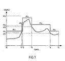
- Figure 7 shows a curve which represents the variation of torque delivered by a stepping motor when a shutter is actuated air inlet. There is a momentary increase in the need for couple.
- the torque thresholds cp 1 , cp 2 , cp 3 are shown as well as the blocking couples cb 1 , cb 2 , cb 3 corresponding to the frequencies f max , f int and f min .
- the torque thresholds cp ' 1 and cp' 2 are also shown. To avoid instability, values for cp ' 1 and cp' 2 will be slightly lower than those of cp 1 and cp 2 , respectively.
- the shutter is driven at maximum speed corresponding to f max between times t 0 (start-up) and t 1 (crossing of cp 1 ) and times t 4 (crossing of cp ' 1 ) and t 5 (arrival of the shutter in final position ).
- t 0 start-up
- t 1 crossing of cp 1
- times t 4 crossing of cp ' 1
- t 5 arrival of the shutter in final position
- the flap is driven at intermediate speed corresponding to f int .
- the flap is driven at minimum speed corresponding to f min .
Abstract
Description
L'invention concerne les actionneurs de volets de distribution ou de mixage d'air ou de recirculation (entrée d'air) dans les installations de climatisation de véhicules automobiles.The invention relates to distribution flap actuators or air mixing or recirculation (air intake) in the installations motor vehicle air conditioning.
Dans de telles installations, les volets sont mûs par des motoréducteurs en réponse à des ordres d'actionnement produits par une unité centrale de commande en fonction des besoins à satisfaire tels que mise en marche ou arrêt de ventilation, réglage de température ambiante, désembuage, dégivrage, ...In such installations, the shutters are moved by geared motors in response to actuation orders produced by a central control unit according to the needs to be satisfied such as ventilation start or stop, room temperature adjustment, demisting, defrosting, ...
Que ce soit pour répondre le plus rapidement aux besoins ou pour faire face à des situations particulières, par exemple détection de pollution, il est souhaitable de déplacer les volets pour les amener dans la position désirée dans le plus bref délai.Whether to respond quickly to needs or to deal with particular situations, for example detection of pollution, it is desirable to move the shutters to bring them into the desired position as soon as possible.
A cet effet, les moteurs des motoréducteurs, généralement des moteurs pas-à-pas sont choisis pour délivrer la puissance nécessaire pour entraíner les volets à vitesse maximale en toutes circonstances, c'est-à-dire quels que soient les fluctuations de la tension d'alimentation et les besoins en couple. Les besoins en couple sont variables non seulement en fonction de la technologie des volets et de la nature de leur cinématique d'entraínement, mais aussi en fonction de conditions instantanées telles que puissance de ventilation, contre-pression exercée sur le volet et s'opposant au mouvement souhaité, température,...For this purpose, the motors of the geared motors, generally stepper motors are chosen to deliver the power needed to drive the flaps at maximum speed in all circumstances, i.e. whatever the fluctuations in the supply voltage and the couple needs. Couples needs are variable not only depending on the technology of the shutters and the nature of their drive kinematics, but also depending on conditions instantaneous such as ventilation power, exerted back pressure on the shutter and opposing the desired movement, temperature, ...
Les motoréducteurs utilisés dans les installations de climatisation connues sont alors surdimensionnés en puissance pour satisfaire les besoins en couple.The gearmotors used in the installations of known air conditioning systems are then oversized in power to satisfy the couple's needs.
L'invention a pour but de permettre l'utilisation de motoréducteurs de plus faible puissance que ceux utilisés de façon habituelle aujourd'hui, afin de diminuer les coûts des installations de climatisation, mais tout en satisfaisant les besoins en couple et sans pénaliser de façon sensible la rapidité d'exécution des ordres d'actionnement.The invention aims to allow the use of lower power gearmotors than those used usual today, in order to lower the costs of the installation of air conditioning, but while satisfying the couple's needs and without significantly penalize the speed of execution of orders actuating.
Ce but est atteint, conformément à l'invention, par un procédé de commande de moteur pas-à-pas d'actionneur selon lequel, lors de l'actionnement du volet, on adapte la fréquence de pilotage du moteur pas-à-pas en fonction du besoin en couple délivré par le moteur pour déplacer le volet.This object is achieved, according to the invention, by a process actuator stepper motor control according to which, when actuation of the shutter, the motor control frequency is adjusted step by step according to the torque requirement delivered by the motor for move the shutter.
L'adaptation de la fréquence de pilotage peut être réalisée en recueillant en permanence une information représentant le besoin en couple délivré par le moteur pour déplacer le volet, en diminuant, le cas échéant, la fréquence de pilotage en réponse à une augmentation détectée du besoin en couple, et, lorsque la fréquence de pilotage est inférieure à une fréquence maximale prédéterminée, en augmentant, le cas échéant, la fréquence de pilotage en réponse à une diminution détectée du besoin en couple.The adaptation of the control frequency can be carried out by continuously collecting information representing the need for torque delivered by the motor to move the flap, decreasing, if necessary the frequency of piloting in response to an increase torque requirement detected, and when the control frequency is lower than a predetermined maximum frequency, by increasing, the if applicable, the frequency of piloting in response to a decrease detected the need for a couple.
Avantageusement, en réponse à un ordre d'actionnement, on commande initialement le fonctionnement du moteur pas-à-pas à la fréquence maximale prédéterminée.Advantageously, in response to an actuation order, we initially controls the operation of the stepper motor at the predetermined maximum frequency.
La variation de la fréquence de pilotage peut être réalisée de façon quasi continue en fonction des fluctuations du besoin en couple détecté, ou par paliers, le passage d'un palier à un autre étant commandé en réponse au franchissement d'un seuil par le besoin en couple détecté.The variation of the control frequency can be carried out from almost continuously according to the fluctuations in the torque requirement detected, or in stages, the passage from one level to another being controlled in response to the crossing of a threshold by the torque requirement detected.
En modulant le cas échéant la fréquence de pilotage, donc la vitesse du moteur pas-à-pas en fonction du besoin en couple, le procédé selon l'invention permet d'optimiser l'utilisation de la puissance disponible. Un surdimensionnement de la puissance, tel qu'il serait nécessaire pour satisfaire des pics de besoin en couple pendant des périodes transitoires lors de la phase de déplacement des volets, devient inutile. Ces périodes transitoires éventuelles représentent rarement plus de 20 % du temps total d'actionnement des volets, de sorte que le ralentissement du moteur pendant ces périodes transitoires éventuelles n'affecte pas sensiblement la durée totale de l'actionnement.By modulating the piloting frequency, if necessary, stepper motor speed according to the torque requirement, the process according to the invention optimizes the use of the available power. An oversizing of the power, as it would be necessary for satisfying peaks in torque requirements during transitional periods during the shutter displacement phase, becomes unnecessary. These periods possible transients rarely represent more than 20% of the time total actuation of the flaps, so that the engine slows down during these possible transitional periods does not significantly affect the total duration of the actuation.
La durée d'actionnement restant réduite, il est possible sans risque d'échauffement excessif de faire fonctionner le moteur pas-à-pas en surpuissance, par application d'une tension d'alimentation correspondant à un mode de fonctionnement en surpuissance. A titre de sécurité, on pourra alors commander l'arrêt du moteur si une température limite d'échauffement est dépassée.The actuation time remaining reduced, it is possible without risk of overheating from operating the stepper motor overpowered, by applying a supply voltage corresponding to an overpowered operating mode. As safety, we can then order the engine to stop if a temperature heating limit is exceeded.
La détection du besoin en couple délivré par le moteur peut être effectuée par mesure d'une grandeur directement ou indirectement représentative du couple telle que mesure de tension sur une phase du moteur, mesure du courant dans un enroulement du moteur ou mesure de la vitesse instantanée de rotation du moteur, un ralentissement en deçà d'une certaine limite traduisant dans ce dernier cas le franchissement d'un seuil de valeur de couple pour la fréquence de pilotage utilisée.The detection of the torque requirement delivered by the engine can be carried out by measuring a quantity directly or indirectly representative of the torque such as voltage measurement on a phase of the motor, measuring current in a motor winding or measuring instantaneous engine rotation speed, deceleration below of a certain limit reflecting in the latter case the crossing of a torque value threshold for the control frequency used.
L'invention a aussi pour but de fournir un actionneur permettant la mise en oeuvre du procédé défini ci-avant.The invention also aims to provide an actuator allowing the implementation of the process defined above.
Ce but est atteint grâce à un actionneur de volet comprenant un moteur pas-à-pas d'entraínement du volet, un circuit d'alimentation électrique du moteur, une entrée de commande et une unité de commande reliée à l'entrée de commande et au circuit d'alimentation électrique pour délivrer au moteur pas-à-pas une tension d'alimentation à une fréquence donnée en réponse à un ordre d'actionnement reçu sur l'entrée de commande, actionneur dans lequel, conformément à l'invention :
- des moyens sont prévus pour fournir à l'unité de commande une information représentant le besoin en couple que doit délivrer le moteur pour déplacer le volet, et
- l'unité de commande comprend des moyens pour adapter la fréquence de pilotage du moteur pas-à-pas en fonction de ladite information représentant le besoin en couple.
- means are provided for supplying the control unit with information representing the torque requirement that the motor must deliver to move the shutter, and
- the control unit comprises means for adapting the piloting frequency of the stepping motor as a function of said information representing the torque requirement.
L'invention a encore pour objet une installation de climatisation de véhicule comprenant au moins un actionneur.The invention also relates to an air conditioning installation vehicle comprising at least one actuator.
L'invention sera mieux comprise à la lecture de la description faite ci-après à titre indicatif mais non limitatif en référence aux dessins annexés, sur lesquels :
- la figure 1 illustre très schématiquement les composants d'une installation de climatisation de véhicule automobile ;
- la figure 2 est un schéma d'un mode de réalisation d'un actionneur de volet conforme à l'invention ;
- les figures 3 et 5 illustrent des processus de gestion de vitesse moteur avec un actionneur tel que celui de la figure 2 ;
- les figures 4 et 6 illustrent schématiquement deux modes de réalisation de circuit de détection de besoin en couple pour un actionneur tel que celui de la figure 2 ; et
- la figure 7 illustre graphiquement la variation dans le temps du couple délivré par un moteur pas-à-pas d'actionneur pendant une phase de déplacement d'un volet entre deux positions.
- FIG. 1 very schematically illustrates the components of a motor vehicle air conditioning installation;
- Figure 2 is a diagram of an embodiment of a shutter actuator according to the invention;
- Figures 3 and 5 illustrate engine speed management processes with an actuator such as that of Figure 2;
- Figures 4 and 6 schematically illustrate two embodiments of the torque demand detection circuit for an actuator such as that of Figure 2; and
- FIG. 7 graphically illustrates the variation over time of the torque delivered by an actuator stepping motor during a phase of movement of a shutter between two positions.
Comme le montre de façon très schématique la figure 1, une
installation de climatisation de véhicule automobile comprend
classiquement une pluralité d'actionneurs 10 (dont seulement deux sont
montrés sur la figure) pour commander le déplacement de volets de
distribution et de mixage d'air afin de réaliser des fonctions souhaitées de
ventilation, réglage de température d'habitacle, désembuage, dégivrage,...
commandées à partir d'un panneau de contrôle 12.As shown very schematically in Figure 1, a
automotive air conditioning system includes
conventionally a plurality of actuators 10 (of which only two are
shown in the figure) to control the movement of
air distribution and mixing in order to achieve desired functions of
ventilation, cabin temperature adjustment, demisting, defrosting, ...
controlled from a
Les actionneurs 10 ainsi que le panneau de commande 12 et
des sondes de température 14 sont reliés à un bus d'énergie 16
acheminant la tension de batterie du véhicule ou une tension dérivée de
celle-ci, et à une liaison d'informations 18.The
En raison de la sophistication des installations de climatisation
de véhicules automobiles, qui se traduit par un nombre croissant de
composants dans ces installations, et pour éviter le recours à de
volumineux faisceaux de fils conducteurs, la liaison 18 est
avantageusement constituée par un bus d'informations. Le bus 18 est
relié à une unité centrale de commande 20. Celle-ci reçoit des
informations d'état provenant du panneau de contrôle 12, des sondes 14
et des actionneurs 10, telles que des informations de position des volets
et transmet des informations de commande, notamment des ordres
d'actionnement de volets par adressage des actionneurs 10, ceux-ci ayant
chacun une adresse spécifique.Due to the sophistication of air conditioning systems
of motor vehicles, which results in an increasing number of
components in these installations, and to avoid recourse to
large bundles of conducting wires, the
Comme le montre plus en détail la figure 2, chaque
actionneur 10 comprend une unité de commande 100 à microprocesseur
reliée au bus d'informations 18 par une interface de bus 102. Un circuit
d'alimentation électrique 104 relié au bus d'énergie 16 comprend des
circuits de filtrage, protection et régulation de tension pour délivrer une
tension logique d'alimentation Vcc à l'unité de commande 100 et une
tension d'alimentation moteur V à un circuit d'interface analogique 106. Un
motoréducteur 110 couplé à un volet de répartition ou mixage d'air (non
représenté) comprend un moteur pas-à-pas 112 qui reçoit du circuit 106 la
tension V sous forme de trains d'impulsions appliqués aux phases du
moteur à une fréquence de pilotage déterminée, sous la commande de
l'unité 100 à laquelle l'interface 106 est reliée. Une interface de données
108 est reliée au motoréducteur 110 et à l'unité de commande 100 pour
transmettre à celle-ci des données d'état, notamment des données de
position du volet, par exemple indiquant l'arrivée du volet en fin de course.As shown in more detail in FIG. 2, each
Une installation de climatisation et un actionneur tels que décrits ci-avant sont connus de l'homme de l'art, de sorte qu'une description plus détaillée n'est pas nécessaire.An air conditioning system and an actuator such as described above are known to those skilled in the art, so that a more detailed description is not necessary.
Conformément à l'invention, l'actionneur 10 comprend en outre
un circuit 120 fournissant une information représentative du besoin en
couple délivré par le moteur pas-à-pas 112, pour déplacer le volet, et
l'unité de commande 100 est programmée de manière à modifier
éventuellement la fréquence de pilotage du moteur 112, et donc la vitesse
de celui-ci, en fonction de l'information fournie par le circuit 120 et reçue
par l'unité de commande par exemple à travers l'interface de données
108.According to the invention, the
Des modes détaillés de réalisation d'un circuit 120 seront
décrits plus loin en référence aux figures 4 et 6.Detailed embodiments of a
La fréquence de pilotage est adaptée pendant la durée
d'actionnement du volet pour ajuster le couple en fonction des besoins. A
une fréquence de pilotage donnée correspond un couple de blocage. Par
couple de blocage, on entend ici le couple maximum qui pourra être exigé
du moteur pour déplacer le volet. Si le besoin en couple devient plus
important, la diminution de la fréquence de pilotage par l'unité 100 permet
d'augmenter le couple de blocage. Si ensuite le besoin en couple diminue,
la fréquence de pilotage peut être ré-augmentée par l'unité 100, avec
diminution correspondante du couple de blocage.The control frequency is adapted during the duration
actuation of the shutter to adjust the torque as required. AT
a given control frequency corresponds to a blocking torque. Through
locking torque, here we mean the maximum torque that may be required
of the motor to move the shutter. If the need for a couple becomes more
important, the reduction in the frequency of piloting by the
La gestion de la fréquence de pilotage du moteur 112 par
l'unité de commande 100 est réalisée par exemple comme suit (figure 3). Management of the 112 motor control frequency by
the
En réponse à un ordre d'actionnement reçu à travers l'interface
de bus 102 (phase 131), le démarrage du moteur 112 est commandé à
une fréquence de pilotage f égale à la fréquence nominale fmax, qui est la
fréquence de pilotage maximale du moteur (phase 132). La fréquence fmax
est choisie pour entraíner initialement le moteur en rotation à une vitesse
maximale correspondant de préférence à un régime de surpuissance. Par
régime de surpuissance, on entend ici un mode de fonctionnement à une
puissance supérieure à la puissance nominale du moteur, ce qui est
rendu possible par la durée réduite de fonctionnement lors d'une phase
d'activation de volet et permet d'optimiser l'utilisation de la puissance
disponible.In response to an actuation command received through the bus interface 102 (phase 131), the starting of the
Lorsqu'il est détecté, à partir de l'information reçue du circuit
120 que le besoin en couple délivré par le moteur 112 augmente au-delà
d'un seuil s1 prédéterminé (test 133), il est examiné si le volet est parvenu
en position finale (test 134). Dans l'affirmative, le moteur est arrêté
(étape 135) ; sinon, la fréquence de pilotage est diminuée d'un incrément
Δf pour passer à la valeur f-Δf (étape 136).When it is detected, on the basis of the information received from the
Lorsqu'après passage à la valeur f-Δf, il est détecté une
diminution du besoin en couple en deçà d'un seuil prédéterminé s2
(test 137), la fréquence de pilotage est augmentée de la valeur Δf
(étape 138) ; sinon, on retourne au test 133.When, after switching to the value f-Δf, a decrease in the torque requirement is detected below a predetermined threshold s 2 (test 137), the control frequency is increased by the value Δf (step 138); otherwise, we return to
Lorsqu'après passage à la valeur f + Δf (étape 138), la valeur
fmax est atteinte (test 139), on retourne au test 133 ; sinon, on retourne au
test 137.When after switching to the value f + Δf (step 138), the value f max is reached (test 139), we return to
Si le test 133 n'indique pas de franchissement du seuil s1, on
reste à la fréquence fmax et on reboucle sur le test 133, si le volet n'est pas
arrivé en position finale (test 140), provoquant l'arrêt du moteur
(étape 141).If the
L'arrivée du volet en position finale peut être reconnue par
l'unité de commande 100 en réponse à la réception d'une information
d'état (par exemple arrivée en butée) correspondant à cette position
finale.The arrival of the flap in the final position can be recognized by
the
Le processus de la figure 3 permet de réaliser une adaptation
de la fréquence de pilotage au besoin en couple de façon quasi-continue,
en choisissant pour l'incrément Δf une valeur relativement faible. A titre
d'exemple, on pourra prévoir une possible excursion de fréquence de
pilotage f entre des valeurs de 600 Hz et 1 200 Hz par incréments de 5Hz.
Une sécurité pourra être prévue pour arrêter le moteur (étape 143) si une
augmentation de besoin en couple est détectée par le test 133 alors que
la fréquence de pilotage est à une valeur minimale fmin (test 142).The process in FIG. 3 makes it possible to adapt the driving frequency to the torque requirement almost continuously, by choosing for the increment Δf a relatively small value. By way of example, it is possible to provide for a possible excursion of the control frequency f between values of 600 Hz and 1,200 Hz in 5Hz increments. A safety device can be provided to stop the engine (step 143) if an increase in the torque requirement is detected by
La figure 4 illustre schématiquement un mode de réalisation
d'un circuit 120 de détection de besoin en couple, de type connu en soi,
pouvant être utilisé pour la mise en oeuvre du processus de la figure 3.FIG. 4 schematically illustrates an embodiment
a torque
La tension vb aux bornes d'une bobine 30 du moteur 112 est
comparée par un comparateur 31 à une tension de référence vref fixée par
une diode 32. La tension de référence est fixée à une valeur supérieure à
la tension normalement présente aux bornes de la bobine 30 lorsque le
moteur délivre le couple nominal correspondant à la fréquence à laquelle
il est piloté.The voltage v b at the terminals of a
Lorsque la tension vb excède vref, traduisant une augmentation
du besoin en couple, le comparateur 31 déclenche un comptage de temps
par un compteur 33. La valeur comptée par le compteur 33 constitue
l'information transmise à l'unité de commande 100 via l'interface 108.When the voltage v b exceeds v ref , reflecting an increase in the torque requirement, the
Le seuil s1 est fixé à une valeur de temps traduisant la persistance de l'augmentation du besoin en couple.The threshold s 1 is fixed at a time value reflecting the persistence of the increase in the torque requirement.
Lorsque la fréquence f a été diminuée en réponse au
dépassement du seuil s1, le compteur 33 peut être remis à zéro par l'unité
de commande 100 via l'interface 106.When the frequency f has been reduced in response to exceeding the threshold s 1 , the
Le seuil s2 est fixé à une valeur de temps inférieure à s1.The threshold s 2 is fixed at a time value less than s 1 .
La figure 5 illustre un autre mode de réalisation de la gestion de
fréquence de pilotage du moteur, la gestion étant réalisée non pas de
façon continue mais par paliers, la fréquence de pilotage pouvant par
exemple prendre trois valeurs : maximale fmax, intermédiaire fint et minimale
fmin. En reprenant l'exemple précédent d'une excursion possible de
fréquence entre 600 et 1 200 Hz, on pourra choisir fmax = 1 200 Hz, fint =
900 Hz et fmin = 600 Hz. En outre, l'information transmise par le circuit 120
est ici représentative de la valeur du couple instantané.FIG. 5 illustrates another embodiment of the motor control frequency management, the management being carried out not continuously but in stages, the control frequency being able for example to take three values: maximum f max , intermediate f int and minimum f min . Using the previous example of a possible frequency excursion between 600 and 1,200 Hz, we can choose f max = 1,200 Hz, f int = 900 Hz and f min = 600 Hz. In addition, the information transmitted by the
En réponse à un ordre d'actionnement reçu (phase 151), le démarrage du moteur est commandé à la fréquence fmax (phase 152).In response to an actuation command received (phase 151), the engine is started at frequency f max (phase 152).
Si le couple instantané dépasse un premier seuil cp1 (test 153),
la fréquence de pilotage f est diminuée pour passer à la valeur intermédiaire
fint (étape 154) ; sinon, il est détecté si le moteur est parvenu en
position finale (test 155) pour, dans l'affirmative, arrêter le moteur
(étape 156) ou, dans la négative revenir au test 153.If the instantaneous torque exceeds a first threshold cp 1 (test 153), the control frequency f is reduced to pass to the intermediate value f int (step 154); otherwise, it is detected if the engine has reached the final position (test 155) to, if so, stop the engine (step 156) or, if not, return to
Après passage à la fréquence fint, il est détecté si le couple instantané dépasse un second seuil cp2 (test 157). Si oui, la fréquence est de nouveau diminuée et passe à fmin (étape 158). On détecte alors si le couple dépasse un troisième seuil cp3 (test 160) afin, le cas échéant, de provoquer un arrêt d'urgence du moteur (étape 161).After switching to the frequency f int , it is detected if the instantaneous torque exceeds a second threshold cp 2 (test 157). If so, the frequency is again decreased and goes to f min (step 158). It is then detected if the torque exceeds a third threshold cp 3 (test 160) in order, if necessary, to cause an emergency stop of the engine (step 161).
Si le seuil cp3 n'est pas dépassé, il est détecté si le couple
instantané devient inférieur à un seuil cp'2 (test 162). Dans l'affirmative, la
fréquence de pilotage est augmentée pour passer à la valeur intermédiaire
fint (phase 154) ; sinon, on recherche si le volet est en position finale
(test 164) pour, dans l'affirmative, arrêter le moteur (étape 165) et, dans la
négative, retourner au test 162.If the threshold cp 3 is not exceeded, it is detected if the instantaneous torque becomes less than a threshold cp ' 2 (test 162). If so, the control frequency is increased to go to the intermediate value f int (phase 154); otherwise, it is investigated whether the shutter is in the final position (test 164) in order, if so, to stop the motor (step 165) and, if not, to return to
Si le test 157 indique que le seuil cp2 n'est pas dépassé, on
recherche si le volet est en position finale (test 166) pour dans
l'affirmative, arrêter le moteur (étape 169) et, dans la négative, détecter si
le couple devient inférieur à un seuil cp'1 (test 167). S'il en est ainsi, la
fréquence de pilotage est augmentée pour passer à la fréquence fmax
(phase 168) ; sinon, on retourne au test 157.If
Après passage à la fréquence fmax, on passe au test 155.After switching to the frequency f max , we go to test 155.
La figure 6 illustre schématiquement un mode de réalisation
d'un circuit 120 de détection de besoin en couple, de type connu en soi,
pouvant être utilisé pour la mise en oeuvre du processus de la figure 3.FIG. 6 schematically illustrates an embodiment
a torque
Une tension vf représentative du courant parcourant une bobine
30a, 30b ou 30c du moteur 112 est prélevée au point milieu d'un diviseur
de tension formé par deux résistances 36, 37 en série avec une bobine,
en l'espèce la bobine 30a. La tension vf est numérisée par un circuit
convertisseur A/N 38 et transmise à l'unité de commande 100 via
l'interface 108.A voltage v f representative of the current flowing through a
La tension vf représente la force contre électromotrice produite lors de la rotation du moteur. Lorsque le moteur ralentit, signe d'une augmentation de couple, la tension vf décroít. Elle est donc inversement proportionnelle au couple délivré par le moteur.The voltage v f represents the electromotive force produced during the rotation of the motor. When the engine slows down, sign of an increase in torque, the voltage v f decreases. It is therefore inversely proportional to the torque delivered by the engine.
Dans le mode de réalisation de la figure 5, les valeurs cp1, cp2, cp3 sont choisies en fonction des couples de blocage pour les fréquences fmax, fint, fmin, plus précisément un peu inférieures à ces couples de blocage. In the embodiment of FIG. 5, the values cp 1 , cp 2 , cp 3 are chosen as a function of the locking torques for the frequencies f max , f int , f min , more precisely a little less than these locking torques .
La figure 7 montre une courbe qui représente la variation du couple délivré par un moteur pas-à-pas lors d'un actionnement d'un volet d'entrée d'air. On constate un accroissement momentané du besoin en couple.Figure 7 shows a curve which represents the variation of torque delivered by a stepping motor when a shutter is actuated air inlet. There is a momentary increase in the need for couple.
Les seuils de couples cp1, cp2, cp3 sont représentés ainsi que les couples de blocage cb1, cb2, cb3 correspondant aux fréquences fmax, fint et fmin.The torque thresholds cp 1 , cp 2 , cp 3 are shown as well as the blocking couples cb 1 , cb 2 , cb 3 corresponding to the frequencies f max , f int and f min .
Les seuils de couple cp'1 et cp'2 sont également représentés. Pour éviter une instabilité, on choisira pour cp'1 et cp'2 des valeurs légèrement inférieures à celles de cp1 et cp2, respectivement.The torque thresholds cp ' 1 and cp' 2 are also shown. To avoid instability, values for cp ' 1 and cp' 2 will be slightly lower than those of cp 1 and cp 2 , respectively.
Le volet est entraíné à vitesse maximale correspondant à fmax entre les temps t0 (démarrage) et t1 (franchissement de cp1) et les temps t4 (franchissement de cp'1) et t5 (arrivée du volet en position finale). Entre les temps t1 et t2 (franchissement de cp2) et les temps t3 (franchissement de cp'2) et t4, le volet est entraíné à vitesse intermédiaire correspondant à fint. Entre les temps t2 et t3, le volet est entraíné à vitesse minimale correspondant à fmin.The shutter is driven at maximum speed corresponding to f max between times t 0 (start-up) and t 1 (crossing of cp 1 ) and times t 4 (crossing of cp ' 1 ) and t 5 (arrival of the shutter in final position ). Between times t 1 and t 2 (crossing of cp 2 ) and times t 3 (crossing of cp ' 2 ) and t 4 , the flap is driven at intermediate speed corresponding to f int . Between times t 2 and t 3 , the flap is driven at minimum speed corresponding to f min .
Bien entendu, le mode de réalisation de la figure 3 pourra être modifié pour piloter la fréquence de pilotage par paliers, tandis que le mode de réalisation de la figure 5 pourra être modifié pour piloter la fréquence de pilotage de façon quasi continue.Of course, the embodiment of Figure 3 may be modified to control the frequency of piloting by stages, while the embodiment of FIG. 5 can be modified to control the pilot frequency almost continuously.
Claims (9)
caractérisé en ce que, lors de l'actionnement du volet, on recueille en permanence une information représentant le besoin en couple délivré par le moteur pas-à-pas (112) pour déplacer le volet, on diminue, le cas échéant, la fréquence de pilotage en réponse à une augmentation détectée du besoin en couple, et, lorsque la fréquence de pilotage est inférieure à une fréquence maximale prédéterminée, on augmente, le cas échéant, la fréquence de pilotage en réponse à une diminution détectée du besoin en couple.Method for controlling the stepping motor of a shutter actuator of a motor vehicle air conditioning installation,
characterized in that , when the shutter is actuated, information is continuously collected representing the need for torque delivered by the stepping motor (112) for moving the shutter, the frequency is reduced, if necessary of piloting in response to a detected increase in the torque requirement, and, when the piloting frequency is less than a predetermined maximum frequency, the piloting frequency is increased, if necessary, in response to a detected decrease in the torque requirement.
Applications Claiming Priority (2)
| Application Number | Priority Date | Filing Date | Title |
|---|---|---|---|
| FR0100988 | 2001-01-25 | ||
| FR0100988A FR2819952B1 (en) | 2001-01-25 | 2001-01-25 | OPTIMIZED SHUTTER ACTUATOR CONTROL OF A MOTOR VEHICLE AIR CONDITIONING SYSTEM |
Publications (3)
| Publication Number | Publication Date |
|---|---|
| EP1227573A2 true EP1227573A2 (en) | 2002-07-31 |
| EP1227573A3 EP1227573A3 (en) | 2002-08-28 |
| EP1227573B1 EP1227573B1 (en) | 2011-04-20 |
Family
ID=8859222
Family Applications (1)
| Application Number | Title | Priority Date | Filing Date |
|---|---|---|---|
| EP02001321A Expired - Lifetime EP1227573B1 (en) | 2001-01-25 | 2002-01-18 | Optimized flap actuator control of a vehicle air conditioner |
Country Status (7)
| Country | Link |
|---|---|
| US (1) | US6710570B2 (en) |
| EP (1) | EP1227573B1 (en) |
| JP (1) | JP2002234333A (en) |
| AT (1) | ATE506740T1 (en) |
| DE (1) | DE60239772D1 (en) |
| ES (1) | ES2362995T3 (en) |
| FR (1) | FR2819952B1 (en) |
Cited By (1)
| Publication number | Priority date | Publication date | Assignee | Title |
|---|---|---|---|---|
| FR3066055A1 (en) * | 2017-05-04 | 2018-11-09 | Valeo Systemes Thermiques | DEVICE FOR CONTROLLING A STEP-BY-STEP MOTOR FOR ACTIVATING A MOBILE AIRBORNE IN A VEHICLE. |
Families Citing this family (5)
| Publication number | Priority date | Publication date | Assignee | Title |
|---|---|---|---|---|
| US7525266B2 (en) * | 2006-01-30 | 2009-04-28 | Honeywell International Inc. | Inverter loop latch with integrated AC detection reset |
| JP2011069336A (en) * | 2009-09-28 | 2011-04-07 | Keihin Corp | Control device of internal combustion engine |
| JP2012121516A (en) * | 2010-12-10 | 2012-06-28 | Aisin Seiki Co Ltd | Grille shutter opening/closing control device |
| DE102012103464A1 (en) * | 2012-04-19 | 2013-10-24 | Brose Fahrzeugteile Gmbh & Co. Kommanditgesellschaft, Hallstadt | Actuator of an air passage device and method for controlling an actuator |
| DE102017205790A1 (en) * | 2017-04-05 | 2018-10-11 | Röchling Automotive SE & Co. KG | Air damper device with gentle end position entry |
Citations (3)
| Publication number | Priority date | Publication date | Assignee | Title |
|---|---|---|---|---|
| US4496891A (en) * | 1982-08-05 | 1985-01-29 | Canon Kabushiki Kaisha | Stepping motor control apparatus |
| EP0242039A2 (en) * | 1986-04-16 | 1987-10-21 | General Motors Corporation | Adaptive controller for a motor vehicle engine throttle operator |
| EP0654892A1 (en) * | 1993-11-19 | 1995-05-24 | Saia Ag | Stepper motor control method |
Family Cites Families (10)
| Publication number | Priority date | Publication date | Assignee | Title |
|---|---|---|---|---|
| JPS55103097A (en) * | 1979-01-29 | 1980-08-06 | Hitachi Ltd | System for driving motor for moving stage |
| CH670343A5 (en) * | 1986-08-20 | 1989-05-31 | Saia Ag | |
| US5107194A (en) * | 1989-08-14 | 1992-04-21 | Xerox Corporation | Stepper motor control to vary output torque |
| JPH07174041A (en) * | 1992-07-27 | 1995-07-11 | Honda Motor Co Ltd | Fuel supply controller of internal combustion engine |
| JP3251782B2 (en) * | 1994-08-09 | 2002-01-28 | 三菱電機株式会社 | Control device for internal combustion engine |
| US6016044A (en) * | 1995-09-11 | 2000-01-18 | Alaris Medical Systems, Inc. | Open-loop step motor control system |
| DE19539753B4 (en) * | 1995-10-26 | 2005-12-22 | Kiekert Ag | Motor vehicle door lock with central locking device |
| JPH10248295A (en) * | 1997-03-03 | 1998-09-14 | Zexel Corp | Actuator controller |
| JP2001136790A (en) * | 1999-11-08 | 2001-05-18 | Canon Inc | Method and apparatus for drive control of stepping motor |
| US6414455B1 (en) * | 2000-04-03 | 2002-07-02 | Alvin J. Watson | System and method for variable drive pump control |
-
2001
- 2001-01-25 FR FR0100988A patent/FR2819952B1/en not_active Expired - Lifetime
-
2002
- 2002-01-18 EP EP02001321A patent/EP1227573B1/en not_active Expired - Lifetime
- 2002-01-18 ES ES02001321T patent/ES2362995T3/en not_active Expired - Lifetime
- 2002-01-18 DE DE60239772T patent/DE60239772D1/en not_active Expired - Lifetime
- 2002-01-18 AT AT02001321T patent/ATE506740T1/en not_active IP Right Cessation
- 2002-01-23 US US10/052,517 patent/US6710570B2/en not_active Expired - Lifetime
- 2002-01-25 JP JP2002016667A patent/JP2002234333A/en active Pending
Patent Citations (3)
| Publication number | Priority date | Publication date | Assignee | Title |
|---|---|---|---|---|
| US4496891A (en) * | 1982-08-05 | 1985-01-29 | Canon Kabushiki Kaisha | Stepping motor control apparatus |
| EP0242039A2 (en) * | 1986-04-16 | 1987-10-21 | General Motors Corporation | Adaptive controller for a motor vehicle engine throttle operator |
| EP0654892A1 (en) * | 1993-11-19 | 1995-05-24 | Saia Ag | Stepper motor control method |
Cited By (1)
| Publication number | Priority date | Publication date | Assignee | Title |
|---|---|---|---|---|
| FR3066055A1 (en) * | 2017-05-04 | 2018-11-09 | Valeo Systemes Thermiques | DEVICE FOR CONTROLLING A STEP-BY-STEP MOTOR FOR ACTIVATING A MOBILE AIRBORNE IN A VEHICLE. |
Also Published As
| Publication number | Publication date |
|---|---|
| DE60239772D1 (en) | 2011-06-01 |
| FR2819952B1 (en) | 2003-04-25 |
| FR2819952A1 (en) | 2002-07-26 |
| JP2002234333A (en) | 2002-08-20 |
| US20020097017A1 (en) | 2002-07-25 |
| US6710570B2 (en) | 2004-03-23 |
| EP1227573A3 (en) | 2002-08-28 |
| ATE506740T1 (en) | 2011-05-15 |
| EP1227573B1 (en) | 2011-04-20 |
| ES2362995T3 (en) | 2011-07-18 |
Similar Documents
| Publication | Publication Date | Title |
|---|---|---|
| US4631467A (en) | Escalator passenger flow control | |
| CA2799941C (en) | Automatic control system for an aircraft engine group, device and aircraft | |
| EP3246194A1 (en) | Air-conditioning system for an electric transport vehicle | |
| EP2626538A1 (en) | Automatic method for controlling an aircraft engine group, device and aircraft | |
| WO2001048574A2 (en) | Device and method for adjusting the power of a power pack driving a helicopter rotor | |
| FR2953077A1 (en) | INVERTER FOR DRIVING A SYNCHRONOUS ELECTRIC MOTOR COMPRISING AN INTEGRATED REGULATOR. | |
| EP1227573B1 (en) | Optimized flap actuator control of a vehicle air conditioner | |
| EP3696084B1 (en) | Method for optimising the ground noise generated by a rotorcraft | |
| EP0658972B1 (en) | Power supply control system for asynchronous motor | |
| EP3718841B1 (en) | Braking system of an aircraft wheel, configurable according to a normal mode or according to an rto mode | |
| FR2996703A1 (en) | METHOD FOR RECOVERING ELECTRIC ENERGY WITH VOLTAGE SMOOTHING ON AN INBOARD ELECTRICAL NETWORK | |
| EP0982825B1 (en) | Apparatus for regulating the speed of rotation of an electrical motor and apparatus for centrifuging comprising such a device | |
| FR2965128A1 (en) | METHOD AND DEVICE FOR MANAGING A GENERATOR OF AN ENERGY RECOVERY SYSTEM OF A MOTOR VEHICLE | |
| FR3012399A1 (en) | VEHICLE LOAD SYSTEM | |
| EP0402220B1 (en) | Method and device to control a step motor | |
| EP1230726B1 (en) | Air conditioning valve actuator for motor vehicle | |
| EP3672059B1 (en) | Adapting the deceleration of a motor as a function of an average rectified voltage | |
| FR2891961A1 (en) | METHOD FOR MAINTAINING A VOLTAGE CONTINUOUS TO THE INPUT OF A CONTINUOUS-VOLTAGE ALTERNATIVE CONVERTER, RECORDING MEDIUM FOR THIS METHOD AND ELECTRIC VEHICLE | |
| FR3066055B1 (en) | DEVICE FOR CONTROLLING A STEP-BY-STEP MOTOR FOR ACTIVATING A MOBILE AIRBORNE IN A VEHICLE. | |
| EP1109688B1 (en) | Heating, ventilating and/or air conditioning device with at least one mobile element controlled by a single-pole motor | |
| FR2503482A1 (en) | METHOD AND SYSTEM FOR POWER SUPPLY CIRCUIT OF AN ASYNCHRONOUS ELECTRIC MACHINE USED AS A DRIVE CONTROL ENGINE | |
| EP4183993B1 (en) | Method for managing power quantities taken from power units of the propulsion assemblies of an aircraft | |
| EP4169142B1 (en) | Electromechanical installation for an aircraft with turbogenerator, emergency stop method for an aicraft turbogenerator and corresponding computer program | |
| JPH0310017B2 (en) | ||
| FR3062973A1 (en) | ALTERNOMETER, MOTOR VEHICLE AND CONTROL METHOD THEREOF |
Legal Events
| Date | Code | Title | Description |
|---|---|---|---|
| PUAI | Public reference made under article 153(3) epc to a published international application that has entered the european phase |
Free format text: ORIGINAL CODE: 0009012 |
|
| PUAL | Search report despatched |
Free format text: ORIGINAL CODE: 0009013 |
|
| AK | Designated contracting states |
Kind code of ref document: A2 Designated state(s): AT BE CH CY DE DK ES FI FR GB GR IE IT LI LU MC NL PT SE TR |
|
| AX | Request for extension of the european patent |
Free format text: AL;LT;LV;MK;RO;SI |
|
| AK | Designated contracting states |
Kind code of ref document: A3 Designated state(s): AT BE CH CY DE DK ES FI FR GB GR IE IT LI LU MC NL PT SE TR |
|
| AX | Request for extension of the european patent |
Free format text: AL;LT;LV;MK;RO;SI |
|
| 17P | Request for examination filed |
Effective date: 20030210 |
|
| AKX | Designation fees paid |
Designated state(s): AT BE CH CY DE DK ES FI FR GB GR IE IT LI LU MC NL PT SE TR |
|
| 17Q | First examination report despatched |
Effective date: 20100218 |
|
| GRAP | Despatch of communication of intention to grant a patent |
Free format text: ORIGINAL CODE: EPIDOSNIGR1 |
|
| GRAS | Grant fee paid |
Free format text: ORIGINAL CODE: EPIDOSNIGR3 |
|
| GRAA | (expected) grant |
Free format text: ORIGINAL CODE: 0009210 |
|
| RAP1 | Party data changed (applicant data changed or rights of an application transferred) |
Owner name: VALEO SYSTEMES THERMIQUES |
|
| AK | Designated contracting states |
Kind code of ref document: B1 Designated state(s): AT BE CH CY DE DK ES FI FR GB GR IE IT LI LU MC NL PT SE TR |
|
| REG | Reference to a national code |
Ref country code: GB Ref legal event code: FG4D Free format text: NOT ENGLISH |
|
| REG | Reference to a national code |
Ref country code: CH Ref legal event code: EP |
|
| REG | Reference to a national code |
Ref country code: CH Ref legal event code: NV Representative=s name: CRONIN INTELLECTUAL PROPERTY |
|
| REG | Reference to a national code |
Ref country code: IE Ref legal event code: FG4D Free format text: LANGUAGE OF EP DOCUMENT: FRENCH |
|
| REF | Corresponds to: |
Ref document number: 60239772 Country of ref document: DE Date of ref document: 20110601 Kind code of ref document: P |
|
| REG | Reference to a national code |
Ref country code: DE Ref legal event code: R096 Ref document number: 60239772 Country of ref document: DE Effective date: 20110601 |
|
| REG | Reference to a national code |
Ref country code: SE Ref legal event code: TRGR |
|
| REG | Reference to a national code |
Ref country code: ES Ref legal event code: FG2A Ref document number: 2362995 Country of ref document: ES Kind code of ref document: T3 Effective date: 20110718 |
|
| REG | Reference to a national code |
Ref country code: NL Ref legal event code: VDEP Effective date: 20110420 |
|
| PG25 | Lapsed in a contracting state [announced via postgrant information from national office to epo] |
Ref country code: PT Free format text: LAPSE BECAUSE OF FAILURE TO SUBMIT A TRANSLATION OF THE DESCRIPTION OR TO PAY THE FEE WITHIN THE PRESCRIBED TIME-LIMIT Effective date: 20110822 |
|
| REG | Reference to a national code |
Ref country code: IE Ref legal event code: FD4D |
|
| PG25 | Lapsed in a contracting state [announced via postgrant information from national office to epo] |
Ref country code: FI Free format text: LAPSE BECAUSE OF FAILURE TO SUBMIT A TRANSLATION OF THE DESCRIPTION OR TO PAY THE FEE WITHIN THE PRESCRIBED TIME-LIMIT Effective date: 20110420 Ref country code: CY Free format text: LAPSE BECAUSE OF FAILURE TO SUBMIT A TRANSLATION OF THE DESCRIPTION OR TO PAY THE FEE WITHIN THE PRESCRIBED TIME-LIMIT Effective date: 20110420 Ref country code: AT Free format text: LAPSE BECAUSE OF FAILURE TO SUBMIT A TRANSLATION OF THE DESCRIPTION OR TO PAY THE FEE WITHIN THE PRESCRIBED TIME-LIMIT Effective date: 20110420 Ref country code: GR Free format text: LAPSE BECAUSE OF FAILURE TO SUBMIT A TRANSLATION OF THE DESCRIPTION OR TO PAY THE FEE WITHIN THE PRESCRIBED TIME-LIMIT Effective date: 20110721 |
|
| PG25 | Lapsed in a contracting state [announced via postgrant information from national office to epo] |
Ref country code: NL Free format text: LAPSE BECAUSE OF FAILURE TO SUBMIT A TRANSLATION OF THE DESCRIPTION OR TO PAY THE FEE WITHIN THE PRESCRIBED TIME-LIMIT Effective date: 20110420 |
|
| PG25 | Lapsed in a contracting state [announced via postgrant information from national office to epo] |
Ref country code: IE Free format text: LAPSE BECAUSE OF FAILURE TO SUBMIT A TRANSLATION OF THE DESCRIPTION OR TO PAY THE FEE WITHIN THE PRESCRIBED TIME-LIMIT Effective date: 20110420 |
|
| PLBE | No opposition filed within time limit |
Free format text: ORIGINAL CODE: 0009261 |
|
| STAA | Information on the status of an ep patent application or granted ep patent |
Free format text: STATUS: NO OPPOSITION FILED WITHIN TIME LIMIT |
|
| PG25 | Lapsed in a contracting state [announced via postgrant information from national office to epo] |
Ref country code: DK Free format text: LAPSE BECAUSE OF FAILURE TO SUBMIT A TRANSLATION OF THE DESCRIPTION OR TO PAY THE FEE WITHIN THE PRESCRIBED TIME-LIMIT Effective date: 20110420 |
|
| 26N | No opposition filed |
Effective date: 20120123 |
|
| REG | Reference to a national code |
Ref country code: DE Ref legal event code: R097 Ref document number: 60239772 Country of ref document: DE Effective date: 20120123 |
|
| BERE | Be: lapsed |
Owner name: VALEO SYSTEMES THERMIQUES Effective date: 20120131 |
|
| PG25 | Lapsed in a contracting state [announced via postgrant information from national office to epo] |
Ref country code: MC Free format text: LAPSE BECAUSE OF NON-PAYMENT OF DUE FEES Effective date: 20120131 |
|
| PG25 | Lapsed in a contracting state [announced via postgrant information from national office to epo] |
Ref country code: BE Free format text: LAPSE BECAUSE OF NON-PAYMENT OF DUE FEES Effective date: 20120131 |
|
| PG25 | Lapsed in a contracting state [announced via postgrant information from national office to epo] |
Ref country code: TR Free format text: LAPSE BECAUSE OF FAILURE TO SUBMIT A TRANSLATION OF THE DESCRIPTION OR TO PAY THE FEE WITHIN THE PRESCRIBED TIME-LIMIT Effective date: 20110420 |
|
| PG25 | Lapsed in a contracting state [announced via postgrant information from national office to epo] |
Ref country code: LU Free format text: LAPSE BECAUSE OF NON-PAYMENT OF DUE FEES Effective date: 20120118 |
|
| REG | Reference to a national code |
Ref country code: FR Ref legal event code: PLFP Year of fee payment: 15 |
|
| REG | Reference to a national code |
Ref country code: FR Ref legal event code: PLFP Year of fee payment: 16 |
|
| REG | Reference to a national code |
Ref country code: FR Ref legal event code: PLFP Year of fee payment: 17 |
|
| REG | Reference to a national code |
Ref country code: CH Ref legal event code: PCAR Free format text: NEW ADDRESS: CHEMIN DE LA VUARPILLIERE 29, 1260 NYON (CH) |
|
| PGFP | Annual fee paid to national office [announced via postgrant information from national office to epo] |
Ref country code: FR Payment date: 20210128 Year of fee payment: 20 Ref country code: CH Payment date: 20210122 Year of fee payment: 20 |
|
| PGFP | Annual fee paid to national office [announced via postgrant information from national office to epo] |
Ref country code: DE Payment date: 20210112 Year of fee payment: 20 Ref country code: SE Payment date: 20210120 Year of fee payment: 20 Ref country code: ES Payment date: 20210208 Year of fee payment: 20 Ref country code: GB Payment date: 20210118 Year of fee payment: 20 |
|
| PGFP | Annual fee paid to national office [announced via postgrant information from national office to epo] |
Ref country code: IT Payment date: 20210118 Year of fee payment: 20 |
|
| REG | Reference to a national code |
Ref country code: DE Ref legal event code: R071 Ref document number: 60239772 Country of ref document: DE |
|
| REG | Reference to a national code |
Ref country code: CH Ref legal event code: PL |
|
| REG | Reference to a national code |
Ref country code: GB Ref legal event code: PE20 Expiry date: 20220117 |
|
| REG | Reference to a national code |
Ref country code: ES Ref legal event code: FD2A Effective date: 20220426 |
|
| PG25 | Lapsed in a contracting state [announced via postgrant information from national office to epo] |
Ref country code: GB Free format text: LAPSE BECAUSE OF EXPIRATION OF PROTECTION Effective date: 20220117 |
|
| PG25 | Lapsed in a contracting state [announced via postgrant information from national office to epo] |
Ref country code: ES Free format text: LAPSE BECAUSE OF EXPIRATION OF PROTECTION Effective date: 20220119 |
|
| P01 | Opt-out of the competence of the unified patent court (upc) registered |
Effective date: 20230528 |