EP3718841B1 - Braking system of an aircraft wheel, configurable according to a normal mode or according to an rto mode - Google Patents
Braking system of an aircraft wheel, configurable according to a normal mode or according to an rto mode Download PDFInfo
- Publication number
- EP3718841B1 EP3718841B1 EP20166520.5A EP20166520A EP3718841B1 EP 3718841 B1 EP3718841 B1 EP 3718841B1 EP 20166520 A EP20166520 A EP 20166520A EP 3718841 B1 EP3718841 B1 EP 3718841B1
- Authority
- EP
- European Patent Office
- Prior art keywords
- braking
- aircraft
- mode
- control means
- electromechanical actuator
- Prior art date
- Legal status (The legal status is an assumption and is not a legal conclusion. Google has not performed a legal analysis and makes no representation as to the accuracy of the status listed.)
- Active
Links
- 230000015556 catabolic process Effects 0.000 claims description 12
- 238000006731 degradation reaction Methods 0.000 claims description 12
- 238000012986 modification Methods 0.000 claims description 4
- 230000004048 modification Effects 0.000 claims description 4
- 238000000034 method Methods 0.000 claims description 3
- 210000000056 organ Anatomy 0.000 description 3
- OKTJSMMVPCPJKN-UHFFFAOYSA-N Carbon Chemical compound [C] OKTJSMMVPCPJKN-UHFFFAOYSA-N 0.000 description 2
- 108091006503 SLC26A1 Proteins 0.000 description 2
- 241001080024 Telles Species 0.000 description 2
- 229910052799 carbon Inorganic materials 0.000 description 2
- 238000010438 heat treatment Methods 0.000 description 2
- 238000007689 inspection Methods 0.000 description 2
- 238000012423 maintenance Methods 0.000 description 2
- 238000005259 measurement Methods 0.000 description 2
- 229920006395 saturated elastomer Polymers 0.000 description 2
- 101100422538 Escherichia coli sat-2 gene Proteins 0.000 description 1
- 240000008042 Zea mays Species 0.000 description 1
- 230000000593 degrading effect Effects 0.000 description 1
- 230000002427 irreversible effect Effects 0.000 description 1
- 238000005457 optimization Methods 0.000 description 1
- 238000005096 rolling process Methods 0.000 description 1
Images

Classifications
-
- B—PERFORMING OPERATIONS; TRANSPORTING
- B60—VEHICLES IN GENERAL
- B60T—VEHICLE BRAKE CONTROL SYSTEMS OR PARTS THEREOF; BRAKE CONTROL SYSTEMS OR PARTS THEREOF, IN GENERAL; ARRANGEMENT OF BRAKING ELEMENTS ON VEHICLES IN GENERAL; PORTABLE DEVICES FOR PREVENTING UNWANTED MOVEMENT OF VEHICLES; VEHICLE MODIFICATIONS TO FACILITATE COOLING OF BRAKES
- B60T8/00—Arrangements for adjusting wheel-braking force to meet varying vehicular or ground-surface conditions, e.g. limiting or varying distribution of braking force
- B60T8/17—Using electrical or electronic regulation means to control braking
- B60T8/1701—Braking or traction control means specially adapted for particular types of vehicles
- B60T8/1703—Braking or traction control means specially adapted for particular types of vehicles for aircrafts
-
- B—PERFORMING OPERATIONS; TRANSPORTING
- B60—VEHICLES IN GENERAL
- B60T—VEHICLE BRAKE CONTROL SYSTEMS OR PARTS THEREOF; BRAKE CONTROL SYSTEMS OR PARTS THEREOF, IN GENERAL; ARRANGEMENT OF BRAKING ELEMENTS ON VEHICLES IN GENERAL; PORTABLE DEVICES FOR PREVENTING UNWANTED MOVEMENT OF VEHICLES; VEHICLE MODIFICATIONS TO FACILITATE COOLING OF BRAKES
- B60T13/00—Transmitting braking action from initiating means to ultimate brake actuator with power assistance or drive; Brake systems incorporating such transmitting means, e.g. air-pressure brake systems
- B60T13/74—Transmitting braking action from initiating means to ultimate brake actuator with power assistance or drive; Brake systems incorporating such transmitting means, e.g. air-pressure brake systems with electrical assistance or drive
- B60T13/741—Transmitting braking action from initiating means to ultimate brake actuator with power assistance or drive; Brake systems incorporating such transmitting means, e.g. air-pressure brake systems with electrical assistance or drive acting on an ultimate actuator
-
- B—PERFORMING OPERATIONS; TRANSPORTING
- B60—VEHICLES IN GENERAL
- B60T—VEHICLE BRAKE CONTROL SYSTEMS OR PARTS THEREOF; BRAKE CONTROL SYSTEMS OR PARTS THEREOF, IN GENERAL; ARRANGEMENT OF BRAKING ELEMENTS ON VEHICLES IN GENERAL; PORTABLE DEVICES FOR PREVENTING UNWANTED MOVEMENT OF VEHICLES; VEHICLE MODIFICATIONS TO FACILITATE COOLING OF BRAKES
- B60T13/00—Transmitting braking action from initiating means to ultimate brake actuator with power assistance or drive; Brake systems incorporating such transmitting means, e.g. air-pressure brake systems
- B60T13/74—Transmitting braking action from initiating means to ultimate brake actuator with power assistance or drive; Brake systems incorporating such transmitting means, e.g. air-pressure brake systems with electrical assistance or drive
- B60T13/746—Transmitting braking action from initiating means to ultimate brake actuator with power assistance or drive; Brake systems incorporating such transmitting means, e.g. air-pressure brake systems with electrical assistance or drive and mechanical transmission of the braking action
-
- B—PERFORMING OPERATIONS; TRANSPORTING
- B60—VEHICLES IN GENERAL
- B60T—VEHICLE BRAKE CONTROL SYSTEMS OR PARTS THEREOF; BRAKE CONTROL SYSTEMS OR PARTS THEREOF, IN GENERAL; ARRANGEMENT OF BRAKING ELEMENTS ON VEHICLES IN GENERAL; PORTABLE DEVICES FOR PREVENTING UNWANTED MOVEMENT OF VEHICLES; VEHICLE MODIFICATIONS TO FACILITATE COOLING OF BRAKES
- B60T8/00—Arrangements for adjusting wheel-braking force to meet varying vehicular or ground-surface conditions, e.g. limiting or varying distribution of braking force
- B60T8/17—Using electrical or electronic regulation means to control braking
- B60T8/172—Determining control parameters used in the regulation, e.g. by calculations involving measured or detected parameters
-
- B—PERFORMING OPERATIONS; TRANSPORTING
- B60—VEHICLES IN GENERAL
- B60T—VEHICLE BRAKE CONTROL SYSTEMS OR PARTS THEREOF; BRAKE CONTROL SYSTEMS OR PARTS THEREOF, IN GENERAL; ARRANGEMENT OF BRAKING ELEMENTS ON VEHICLES IN GENERAL; PORTABLE DEVICES FOR PREVENTING UNWANTED MOVEMENT OF VEHICLES; VEHICLE MODIFICATIONS TO FACILITATE COOLING OF BRAKES
- B60T8/00—Arrangements for adjusting wheel-braking force to meet varying vehicular or ground-surface conditions, e.g. limiting or varying distribution of braking force
- B60T8/32—Arrangements for adjusting wheel-braking force to meet varying vehicular or ground-surface conditions, e.g. limiting or varying distribution of braking force responsive to a speed condition, e.g. acceleration or deceleration
- B60T8/321—Arrangements for adjusting wheel-braking force to meet varying vehicular or ground-surface conditions, e.g. limiting or varying distribution of braking force responsive to a speed condition, e.g. acceleration or deceleration deceleration
- B60T8/325—Systems specially adapted for aircraft
-
- B—PERFORMING OPERATIONS; TRANSPORTING
- B64—AIRCRAFT; AVIATION; COSMONAUTICS
- B64C—AEROPLANES; HELICOPTERS
- B64C25/00—Alighting gear
- B64C25/32—Alighting gear characterised by elements which contact the ground or similar surface
- B64C25/42—Arrangement or adaptation of brakes
- B64C25/44—Actuating mechanisms
-
- B—PERFORMING OPERATIONS; TRANSPORTING
- B60—VEHICLES IN GENERAL
- B60T—VEHICLE BRAKE CONTROL SYSTEMS OR PARTS THEREOF; BRAKE CONTROL SYSTEMS OR PARTS THEREOF, IN GENERAL; ARRANGEMENT OF BRAKING ELEMENTS ON VEHICLES IN GENERAL; PORTABLE DEVICES FOR PREVENTING UNWANTED MOVEMENT OF VEHICLES; VEHICLE MODIFICATIONS TO FACILITATE COOLING OF BRAKES
- B60T2250/00—Monitoring, detecting, estimating vehicle conditions
- B60T2250/04—Vehicle reference speed; Vehicle body speed
-
- Y—GENERAL TAGGING OF NEW TECHNOLOGICAL DEVELOPMENTS; GENERAL TAGGING OF CROSS-SECTIONAL TECHNOLOGIES SPANNING OVER SEVERAL SECTIONS OF THE IPC; TECHNICAL SUBJECTS COVERED BY FORMER USPC CROSS-REFERENCE ART COLLECTIONS [XRACs] AND DIGESTS
- Y02—TECHNOLOGIES OR APPLICATIONS FOR MITIGATION OR ADAPTATION AGAINST CLIMATE CHANGE
- Y02T—CLIMATE CHANGE MITIGATION TECHNOLOGIES RELATED TO TRANSPORTATION
- Y02T50/00—Aeronautics or air transport
- Y02T50/80—Energy efficient operational measures, e.g. ground operations or mission management
Definitions
- the invention relates to the field of electrical aircraft braking systems.
- An aircraft electric braking system comprises brakes associated with so-called “braked” wheels of the aircraft.
- the brake of a braked wheel comprises friction members, for example a stack of carbon discs, and electromechanical actuators mounted on an actuator carrier and arranged to apply a controlled braking force to the stack of discs to brake the wheel .
- the electric braking system also comprises control means which, from a braking setpoint produced by a pilot of the aircraft or by an automatic pilot system, produce pilot currents intended for the electric motors of the electromechanical actuators .
- the control means include electrical equipment (control units, computers, controllers, etc.), the number and position of which in the aircraft depend on the number of braked wheels and the architecture of the electrical braking system, which is more or less centralized or distributed.
- WO2007/084449 A2 discloses a system having two modes with a first pair of electric brake actuators associated with a range of low brake application force responsive to low brake application force commands and a second pair of electric brake actuators associated with a range of high brake application force responsive to high brake application force commands.
- the electric braking system is mainly used to brake the aircraft when taxiing on the runway after landing, during taxiing in general, and when parking the aircraft.
- each electromechanical actuator of each brake comprises a park braking member which makes it possible to block the rotor of the electric motor of said electromechanical actuator after a braking force has been exerted on the stack of discs.
- RTO Rejected TakeOff
- Speed V1 is the maximum ground speed of the aircraft at which an RTO can be performed. Beyond speed V1, it is no longer possible to abort the takeoff.
- An RTO is a situation that can be very severe for the brakes, since the brakes must brake the aircraft when the aircraft is loaded to the maximum and traveling at a speed that can be high.
- Electromechanical actuators in particular, have to produce a very high braking force and are therefore subject to very high stresses.
- Electromechanical actuators are designed to withstand the stresses of an RTO. This is generally the case of a maximum energy RTO which defines the upper limit of the force range applicable to the brake by the electromechanical actuators.
- Electromechanical actuators are therefore dimensioned to produce a limit operational effort corresponding to a case of RTO at maximum energy, and are consequently relatively heavy and bulky.
- the aircraft therefore permanently carries “oversized” electromechanical actuators, of significant mass and bulk, in anticipation of a relatively rare event following which the electromechanical actuators are generally discarded.
- the object of the invention is to reduce the weight and size of an electric braking system of an aircraft.
- the control means are configurable according to a first mode, in which the control current is such that the controlled braking force cannot exceed the first maximum threshold, and according to a second mode, in which the control current is such that the controlled braking force can reach the second maximum threshold.
- the electric braking system further comprises configuration means arranged to configure the control means according to the second mode in a situation preceding a possible aborted take-off (RTO) of the aircraft, and according to the first mode otherwise.
- RTO aborted take-off
- the electromechanical actuator is controlled to produce a controlled braking force less than or equal to the first maximum threshold.
- the controlled braking force is sufficient for normal braking and does not cause any degradation of the electromechanical actuator.
- the electromechanical actuator is controlled to produce a controlled braking force which can reach the second maximum threshold.
- the controlled braking effort makes it possible to achieve an RTO at maximum energy.
- the electromechanical actuator can be degraded (while ensuring that the braking is carried out effectively), which is not a problem, because the electromechanical actuator will be inspected and possibly scrapped after the RTO.
- the electric braking system has therefore been optimized by adapting the dimensioning of the electromechanical actuator to its actual use.
- the case of the RTO in maximum energy no longer corresponds to a limit operational effort that the electromechanical actuator must normally produce, but to an ultimate effort.
- This dimensioning makes it possible to reduce the mass, the size and the cost of the electromechanical actuator and therefore of the electric braking system, without degrading the performance of the electric braking system.
- the modification of the braking law consists in modifying the parameters of the braking law, the said parameters comprising a maximum control which limits a force control intended to control the electromechanical actuator, and a saturation threshold of a motor current command electric of the electromechanical actuator.
- the electric braking system according to the invention 1 is here integrated into an airplane and is used to brake the braked wheels 2 of the airplane and therefore the airplane itself.
- the electric braking system 1 can be configured according to the type of braking ordered and, more particularly, depending on whether the braking ordered is normal braking, that is to say braking following a landing, during taxiing of the aircraft or for parking, or braking intended to abort a take-off (RTO).
- the braking ordered is normal braking, that is to say braking following a landing, during taxiing of the aircraft or for parking, or braking intended to abort a take-off (RTO).
- the electric braking system 1 firstly comprises a plurality of brakes 3, each brake 3 being associated with a braked wheel 2.
- the brake 3 comprises friction members, in this case a stack of carbon discs 4, and a plurality of electromechanical actuators 5 carried by an actuator carrier.
- Each electromechanical actuator 5 comprises an electric motor and a pusher adapted to be moved by the electric motor to press the stack of discs 4.
- the electromechanical actuator 5 is thus intended to produce a controlled braking force on the stack of discs 4.
- Each electromechanical actuator 5 is designed and dimensioned in a very particular way specific to the invention.
- Each electromechanical actuator 5 is designed so that, when it applies to the stack of discs 4 a controlled braking force less than or equal to a first maximum threshold, no functional or structural degradation of the electromechanical actuator 5 occurs.
- “functional performance” is meant the performance related to the primary function of the electromechanical actuator 5, which is to produce a braking force controlled from a control current supplied to its electric motor, but also the performance in in terms of reliability, service life, availability, resistance over time to external constraints, etc.
- the first maximum threshold is therefore a limit operational effort that the electromechanical actuator 5 can generate when it operates in a normal operating range.
- the normal operating range corresponds to normal braking, that is to say braking following a landing, during taxiing and for parking the aircraft.
- the second maximum threshold corresponds to a maximum force limit that an electromechanical actuator 5 is capable of producing during braking aimed at interrupting a take-off.
- the second maximum threshold makes it possible to achieve an RTO at maximum energy.
- the degradation has a "minor” impact: the electromechanical actuator 5 indeed produces the controlled braking force and makes it possible to implement the RTO but, following braking, the electromechanical actuator 5 must be checked and possibly scrapped because of the degradation it has suffered.
- the second maximum threshold therefore corresponds to an “ultimate” braking force of the electromechanical actuator 5.
- the electromechanical actuator 5 will produce a controlled braking force which can reach the second maximum threshold, this who risks damage the electromechanical actuator 5.
- the electromechanical actuator 5 is capable of producing the controlled braking force despite the possible degradation, so that , for the aircraft, the achievement of the end of the RTO cycle is guaranteed.
- This dimensioning is notably based on less demanding “mechanical” specifications.
- the acceptable and required elasticity limit of the mechanical components of the electromechanical actuator 5 is lowered, which makes it possible to reduce their volume and their mass.
- the electric motor is also a possible source of optimization. It would be possible to reduce the volume of the electric motor. Indeed, in the case of an RTO at maximum energy, the electric motor undergoes very significant heating. The electric motor must have a large volume in order to be able to withstand this heating without any degradation.
- the volume of the electric motor can be reduced.
- the electric braking system 1 further comprises control means 7.
- the control means 7 control one or more electromechanical actuators 5 positioned on one or more brakes 3.
- the control means 7 comprise one or more electrical equipment, in which are implemented a control module 8 and a power module 9.
- the control module 8 implements braking laws comprising one or more servo loops.
- the servo loops include a force servo (in torque for example) and a current servo.
- the power module 9 comprises one or more inverters to produce control currents intended for the electromechanical actuator(s) 5.
- the control module 8 acquires a braking setpoint C f which is produced for example by the pilot of the airplane thanks to the pedals.
- control module 8 converts the braking setpoint C f into force setpoints each intended to control an electromechanical actuator 5.
- control module 8 For each electromechanical actuator 5, the control module 8 transforms the force setpoint into a force command, which itself is converted into a current setpoint from which a current command is produced.
- the power module 9 acquires the current command and generates from the current command and a power supply (coming from a power bus traveling in the aircraft) a control current I p actually transmitted to the electric motor of the electromechanical actuator 5.
- the control current I p controls the electromechanical actuator 5 so that the latter produces a force controlled braking.
- control current is meant a direct or alternating current or even multiphase currents.
- the control means 7 can be configured according to a first mode, in which the control current I p is such that the controlled braking force cannot exceed the first maximum threshold, and according to a second mode, in which the control current is such that the controlled braking force can reach the second maximum threshold.
- the first mode is used for normal braking, and the second mode for braking aimed at aborting a takeoff.
- the configuration of the control means 7 is modified by a modification of a braking law implemented in the control module 8 of the control means 7.
- the modification of the braking law consists in modifying parameters of the braking law . These parameters include a maximum command which limits the force command intended to control the electromechanical actuator 5, and a saturation threshold of the current command.
- the first mode is characterized by a first braking law defined with a first maximum command and a first saturation threshold.
- the force command produced by the control module 8 from the braking setpoint is limited by the first maximum command and therefore cannot exceed it.
- the current command is saturated by the first saturation threshold. As long as the current command remains less than or equal to the first saturation threshold, an increase in the current command causes an increase in the control current. When the current command reaches the first saturation threshold, the pilot current no longer increases.
- the first saturation threshold ensures that a force command equal to the first maximum command can be reached but cannot be exceeded.
- the first saturation threshold secures the command: even if the force command exceeds the first maximum command, the current command cannot exceed the first saturation threshold so that the controlled braking force applied by the electromechanical actuator 5 cannot exceed the first maximum threshold.
- the second mode is characterized by a second braking law defined with a second maximum command and a second saturation threshold.
- the second saturation threshold ensures that a force command equal to the second maximum command can be reached.
- the second maximum command is greater than the first maximum command, typically by 10% to 30%, preferably by approximately 20%.
- the electric braking system 1 further comprises configuration means 10.
- the configuration means 10 configure the control means 7 according to the second mode in a situation preceding a possible aborted take-off (RTO) of the aircraft, and according to the first mode otherwise.
- RTO aborted take-off
- a force command that can reach the second maximum command is available to brake the airplane.
- a measurement of the ground speed V s of the aircraft is advantageously used produced by an inertial unit 12 of the aircraft, which is more precise and more reliable than a measurement of speed produced by the tachometers fitted wheels braked 2.
- a maintenance message is generated.
- the maintenance message indicates that an RTO has just taken place and that the electromechanical actuator 5 must undergo an inspection.
- the electromechanical actuator 5 is checked and discarded if necessary. On the other hand, as long as the first maximum order is not exceeded, an inspection is not necessary.
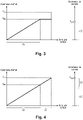
- the picture 2 relates to a prior art electric braking system.
- a single braking law is used.
- the effort command increases as the effort setpoint increases.
- the force command is limited by a single maximum command C M .
- the current command is saturated by a single saturation threshold S sat which allows the controlled braking force produced by the electromechanical actuator to reach the maximum command C M without exceeding it.
- the total range which limits the effort setpoint comprises a nominal range 15 and an additional range 16 provided for the case of the RTO.
- the additional range 16 corresponds to a force command less than or equal to the single maximum command C M , this range is accessible to the pilot whatever the braking.
- the total range which limits the current command comprises a nominal range 17 and an additional range 18 provided for the case of the RTO.
- the single saturation threshold S sat therefore does not prevent, during normal braking, having a current command which corresponds to the additional range 18 provided for the case of the RTO.
- the pilot can therefore control, at the time of normal braking, a braking force within a range of force provided for a case of RTO, which is useless and risks wearing out the brakes prematurely.
- the electromechanical actuators are oversized, since they are sized to produce without damage a controlled braking force corresponding to the maximum command C M (and therefore to an RTO at maximum energy), following which they are generally discarded.
- the picture 3 relates to the electric braking system according to the invention 1, when the control means 7 are configured according to the first mode.
- the force control to control an electromechanical actuator 5 as well as the current control are adjusted in accordance with the braking performance required for normal braking, that is to say for a braking following a landing, braking during taxiing and braking for parking the aircraft.
- the pilot can therefore no longer control, at the time of normal braking, a braking force within a range of force provided for a case of RTO.
- the figure 4 relates to the electric braking system according to the invention 1, when the control means 7 are configured according to the second mode.
- the upper limit of the effort command is raised to reach the second maximum command C M2 and the limitation of the piloting current is raised so that the current command can reach the second saturation threshold S sat2 .
- the effort command continues to increase and can reach the second maximum command C M2 .
- the current command can reach the range additional 22.
- the pilot can therefore this time command a braking force which reaches the second maximum command C M2 , and which enables him to brake the airplane in the event of an RTO at maximum energy.
- control means can be implemented in one or more electrical equipment and in any type of architecture.
- the control module and the piloting module can belong to the same electrical equipment, but not necessarily.
- the configuration means can belong to the same electrical equipment as the control means, or else be integrated into the control means (it can be part of the software implemented in the control means), but not necessarily.
Description
L'invention concerne le domaine des systèmes de freinage électriques d'aéronefs.The invention relates to the field of electrical aircraft braking systems.
Un système de freinage électrique d'aéronef comporte des freins associés à des roues dites « freinées » de l'aéronef.An aircraft electric braking system comprises brakes associated with so-called “braked” wheels of the aircraft.
Le frein d'une roue freinée comporte des organes de friction, par exemple une pile de disques de carbone, et des actionneurs électromécaniques montés sur un porte-actionneurs et agencés pour appliquer un effort de freinage commandé sur la pile de disques pour freiner la roue.The brake of a braked wheel comprises friction members, for example a stack of carbon discs, and electromechanical actuators mounted on an actuator carrier and arranged to apply a controlled braking force to the stack of discs to brake the wheel .
Le système de freinage électrique comporte aussi des moyens de commande qui, à partir d'une consigne de freinage produite par un pilote de l'aéronef ou par un système de pilotage automatique, produisent des courants de pilotage à destination des moteurs électriques des actionneurs électromécaniques. Les moyens de commande comprennent des équipements électriques (unités de commande, calculateurs, contrôleurs, etc.) dont le nombre et la position dans l'aéronef dépendent du nombre de roues freinées et de l'architecture du système de freinage électrique, qui est plus ou moins centralisée ou distribuée.
Le système de freinage électrique est principalement utilisé pour freiner l'aéronef lorsqu'il roule sur la piste suite à son atterrissage, pendant le roulage de manière générale, et lors du parking de l'aéronef.The electric braking system is mainly used to brake the aircraft when taxiing on the runway after landing, during taxiing in general, and when parking the aircraft.
Le freinage de l'aéronef suite à son atterrissage et pendant le roulage est commandé par le pilote grâce des pédales équipant le cockpit. Pour réaliser le freinage de parc, chaque actionneur électromécanique de chaque frein comprend un organe de freinage de parc qui permet de bloquer le rotor du moteur électrique dudit actionneur électromécanique après qu'un effort de freinage a été exercé sur la pile de disques.The braking of the aircraft following its landing and during taxiing is controlled by the pilot using the pedals fitted in the cockpit. To perform the braking of park, each electromechanical actuator of each brake comprises a park braking member which makes it possible to block the rotor of the electric motor of said electromechanical actuator after a braking force has been exerted on the stack of discs.
A de rares occasions, le système de freinage électrique peut aussi être utilisé pour interrompre un décollage. On utilise généralement le sigle RTO (pour Rejected TakeOff) pour désigner une interruption de décollage. Le RTO consiste à interrompre le décollage lorsque l'aéronef est au sol et roule pour décoller. On appelle vitesse V1 la vitesse au sol maximale de l'aéronef à laquelle un RTO peut être effectué. Au-delà de la vitesse V1, il n'est plus possible d'interrompre le décollage.On rare occasions, the electric braking system may also be used to abort a takeoff. The acronym RTO (for Rejected TakeOff ) is generally used to designate an aborted takeoff. RTO consists of aborting takeoff when the aircraft is on the ground and rolling for takeoff. Speed V1 is the maximum ground speed of the aircraft at which an RTO can be performed. Beyond speed V1, it is no longer possible to abort the takeoff.
Un RTO est une situation pouvant être très sévère pour les freins, puisque les freins doivent freiner l'aéronef alors que l'aéronef est chargé au maximum et roule à une vitesse qui peut être importante.An RTO is a situation that can be very severe for the brakes, since the brakes must brake the aircraft when the aircraft is loaded to the maximum and traveling at a speed that can be high.
Les actionneurs électromécaniques, en particulier, doivent produire un effort de freinage très élevé et sont donc soumis à de très fortes contraintes.Electromechanical actuators, in particular, have to produce a very high braking force and are therefore subject to very high stresses.
Les actionneurs électromécaniques sont conçus pour supporter les contraintes d'un RTO. C'est généralement le cas d'un RTO à énergie maximale qui définit la borne haute du domaine d'effort applicable sur le frein par les actionneurs électromécaniques.Electromechanical actuators are designed to withstand the stresses of an RTO. This is generally the case of a maximum energy RTO which defines the upper limit of the force range applicable to the brake by the electromechanical actuators.
Les actionneurs électromécaniques sont donc dimensionnés pour produire un effort opérationnel limite correspondant à un cas de RTO à énergie maximale, et sont par conséquent relativement lourds et volumineux.Electromechanical actuators are therefore dimensioned to produce a limit operational effort corresponding to a case of RTO at maximum energy, and are consequently relatively heavy and bulky.
L'aéronef embarque donc en permanence des actionneurs électromécaniques « surdimensionnés », de masse et d'encombrement importants, en prévision d'un événement relativement rare suite auquel les actionneurs électromécaniques sont généralement rebutés.The aircraft therefore permanently carries “oversized” electromechanical actuators, of significant mass and bulk, in anticipation of a relatively rare event following which the electromechanical actuators are generally discarded.
L'invention a pour objet de réduire la masse et l'encombrement d'un système de freinage électrique d'un aéronef.The object of the invention is to reduce the weight and size of an electric braking system of an aircraft.
En vue de la réalisation de ce but, on propose un système de freinage électrique d'une roue d'aéronef, comportant :
- un frein comprenant des organes de friction et au moins un actionneur électromécanique conçu de sorte que, lorsqu'il applique sur les organes de friction un effort de freinage commandé inférieur ou égal à un premier seuil maximum, aucune dégradation fonctionnelle ou structurelle de l'actionneur électromécanique ne se produit, et lorsqu'il applique sur les organes de friction un effort de freinage commandé supérieur au premier seuil maximum mais inférieur ou égal à un deuxième seuil maximum, une dégradation fonctionnelle et/ou structurelle est susceptible de se produire sans empêcher l'actionneur électromécanique d'appliquer l'effort de freinage commandé ;
- des moyens de commande agencés pour produire un courant de pilotage à destination d'un moteur électrique de l'actionneur électromécanique.
- a brake comprising friction members and at least one electromechanical actuator designed so that, when it applies to the friction members a controlled braking force less than or equal to a first maximum threshold, there is no functional or structural degradation of the actuator electromechanical does not occur, and when it applies to the friction members a controlled braking force greater than the first maximum threshold but less than or equal to a second maximum threshold, a functional and / or structural degradation is likely to occur without preventing the electromechanical actuator to apply the controlled braking force;
- control means arranged to produce a control current intended for an electric motor of the electromechanical actuator.
Les moyens de commande sont configurables selon un premier mode, dans lequel le courant de pilotage est tel que l'effort de freinage commandé ne peut dépasser le premier seuil maximum, et selon un deuxième mode, dans lequel le courant de pilotage est tel que l'effort de freinage commandé peut atteindre le deuxième seuil maximum.The control means are configurable according to a first mode, in which the control current is such that the controlled braking force cannot exceed the first maximum threshold, and according to a second mode, in which the control current is such that the controlled braking force can reach the second maximum threshold.
Le système de freinage électrique comporte en outre des moyens de configuration agencés pour configurer les moyens de commande selon le deuxième mode dans une situation précédant une possible interruption de décollage (RTO) de l'aéronef, et selon le premier mode sinon.The electric braking system further comprises configuration means arranged to configure the control means according to the second mode in a situation preceding a possible aborted take-off (RTO) of the aircraft, and according to the first mode otherwise.
Ainsi, lorsque les moyens de commande sont configurés selon le premier mode, qui correspond à un freinage normal, l'actionneur électromécanique est piloté pour produire un effort de freinage commandé inférieur ou égal au premier seuil maximum. L'effort de freinage commandé est suffisant pour un freinage normal et ne provoque aucune dégradation de l'actionneur électromécanique.Thus, when the control means are configured according to the first mode, which corresponds to normal braking, the electromechanical actuator is controlled to produce a controlled braking force less than or equal to the first maximum threshold. The controlled braking force is sufficient for normal braking and does not cause any degradation of the electromechanical actuator.
Par contre, lorsque les moyens de commande sont configurés selon le deuxième mode, qui correspond à un cas de RTO, l'actionneur électromécanique est piloté pour produire un effort de freinage commandé qui peut atteindre le deuxième seuil maximum. L'effort de freinage commandé permet de réaliser un RTO à énergie maximale. L'actionneur électromécanique peut être dégradé (tout en assurant que le freinage est réalisé de manière efficace), ce qui n'est pas problématique, car l'actionneur électromécanique sera inspecté et éventuellement rebuté après le RTO.On the other hand, when the control means are configured according to the second mode, which corresponds to a case of RTO, the electromechanical actuator is controlled to produce a controlled braking force which can reach the second maximum threshold. The controlled braking effort makes it possible to achieve an RTO at maximum energy. The electromechanical actuator can be degraded (while ensuring that the braking is carried out effectively), which is not a problem, because the electromechanical actuator will be inspected and possibly scrapped after the RTO.
On a donc optimisé le système de freinage électrique en adaptant le dimensionnement de l'actionneur électromécanique à son usage réel. Le cas du RTO à énergie maximale ne correspond plus à un effort opérationnel limite que doit produire normalement l'actionneur électromécanique, mais à un effort ultime. Ce dimensionnement permet de réduire la masse, l'encombrement et le coût de l'actionneur électromécanique et donc du système de freinage électrique, sans dégrader les performances du système de freinage électrique.The electric braking system has therefore been optimized by adapting the dimensioning of the electromechanical actuator to its actual use. The case of the RTO in maximum energy no longer corresponds to a limit operational effort that the electromechanical actuator must normally produce, but to an ultimate effort. This dimensioning makes it possible to reduce the mass, the size and the cost of the electromechanical actuator and therefore of the electric braking system, without degrading the performance of the electric braking system.
On propose de plus un système de freinage électrique tel que précédemment décrit, dans lequel les moyens de configuration sont agencés pour configurer les moyens de commande selon le deuxième mode avant chaque décollage de l'aéronef.There is also proposed an electric braking system as previously described, in which the configuration means are arranged to configure the control means according to the second mode before each take-off of the aircraft.
On propose aussi un système de freinage électrique tel que précédemment décrit, dans lequel les moyens de configuration sont agencés pour configurer les moyens de commande selon le deuxième mode au cours de chaque décollage, lorsqu'une vitesse au sol de l'aéronef dépasse un seuil de vitesse prédéterminé.There is also proposed an electric braking system as previously described, in which the configuration means are arranged to configure the control means according to the second mode during each takeoff, when a ground speed of the aircraft exceeds a threshold predetermined speed.
On propose de plus un système de freinage électrique tel que précédemment décrit, dans lequel les moyens de configuration sont agencés pour modifier une loi de freinage mise en œuvre dans les moyens de commande pour configurer les moyens de commande.There is also proposed an electric braking system as previously described, in which the configuration means are arranged to modify a braking law implemented in the control means to configure the control means.
On propose de plus un système de freinage électrique tel que précédemment décrit, dans lequel la modification de la loi de freinage consiste à modifier des paramètres de la loi de freinage, lesdits paramètres comprenant une commande maximale qui limite une commande d'effort destinée à commander l'actionneur électromécanique, et un seuil de saturation d'une commande de courant du moteur électrique de l'actionneur électromécanique.There is also proposed an electric braking system as previously described, in which the modification of the braking law consists in modifying the parameters of the braking law, the said parameters comprising a maximum control which limits a force control intended to control the electromechanical actuator, and a saturation threshold of a motor current command electric of the electromechanical actuator.
On propose en outre un aéronef comprenant un système de freinage électrique tel que précédemment décrit.There is also proposed an aircraft comprising an electric braking system as previously described.
On propose de plus un procédé de freinage mis en œuvre dans un système de freinage électrique tel que précédemment décrit, comprenant les étapes de :
- détecter si l'aéronef se trouve ou non dans une situation précédant une possible interruption de décollage (RTO) de l'aéronef ;
- si l'aéronef ne se trouve pas dans une telle situation, faire configurer les moyens de commande par les moyens de configuration selon le premier mode ;
- si l'aéronef se trouve dans une telle situation, faire configurer les moyens de commande par les moyens de configuration selon le deuxième mode.
- detecting whether or not the aircraft is in a situation preceding a possible aborted take-off (RTO) of the aircraft;
- if the aircraft is not in such a situation, having the control means configured by the configuration means according to the first mode;
- if the aircraft is in such a situation, have the control means configured by the configuration means according to the second mode.
L'invention sera mieux comprise à la lumière de la description qui suit d'un mode de mise en œuvre particulier non limitatif de l'invention.The invention will be better understood in the light of the following description of a particular non-limiting mode of implementation of the invention.
Il sera fait référence aux dessins annexés, parmi lesquels :
- [
Fig.1 ]
lafigure 1 représente le système de freinage électrique selon l'invention ; - [
Fig.2 ]
lafigure 2 représente, pour un système de freinage électrique de l'art antérieur, un premier graphique comprenant une courbe d'une commande d'effort d'un actionneur électromécanique en fonction d'une consigne d'effort, et un deuxième graphique représentant des niveaux d'une commande de courant du moteur de l'actionneur électromécanique en fonction du type de freinage ; - [
Fig.3 ]
lafigure 3 représente des graphiques similaires à ceux de lafigure 2 dans le cas d'un système de freinage électrique selon l'invention, les moyens de commande étant configurés selon un premier mode ; - [
Fig.4 ]
lafigure 4 représente des graphiques similaires à ceux de lafigure 2 dans le cas d'un système de freinage électrique selon l'invention, les moyens de commande étant configurés selon un deuxième mode.
- [
Fig.1 ]
thefigure 1 represents the electric braking system according to the invention; - [
Fig.2 ]
thefigure 2 represents, for an electric braking system of the prior art, a first graph comprising a curve of a force command of an electromechanical actuator as a function of a force setpoint, and a second graph representing levels of a motor current control the electromechanical actuator depending on the type of braking; - [
Fig.3 ]
thepicture 3picture 2 - [
Fig.4 ]
thefigure 4 represents graphs similar to those of thepicture 2
En référence à la
Le système de freinage électrique 1 est configurable selon le type de freinage commandé et, plus particulièrement, selon que le freinage commandé est un freinage normal, c'est-à-dire un freinage suite à un atterrissage, au cours du roulage de l'avion ou pour le parking, ou bien un freinage destiné à interrompre un décollage (RTO).The
Le système de freinage électrique 1 comporte tout d'abord une pluralité de freins 3, chaque frein 3 étant associé à une roue freinée 2.The
Le frein 3 comprend des organes de friction, en l'occurrence une pile de disques de carbone 4, et une pluralité d'actionneurs électromécaniques 5 portés par un porte-actionneurs.The
Chaque actionneur électromécanique 5 comprend un moteur électrique et un poussoir apte à être déplacé par le moteur électrique pour presser la pile de disques 4. L'actionneur électromécanique 5 est ainsi destiné à produire un effort de freinage commandé sur la pile de disques 4.Each
Chaque actionneur électromécanique 5 est conçu et dimensionné d'une manière bien particulière et propre à l'invention.Each
Chaque actionneur électromécanique 5 est conçu de sorte que, lorsqu'il applique sur la pile de disques 4 un effort de freinage commandé inférieur ou égal à un premier seuil maximum, aucune dégradation fonctionnelle ou structurelle de l'actionneur électromécanique 5 ne se produit.Each
Cela signifie tout d'abord que, après le freinage, les performances fonctionnelles de l'actionneur électromécanique 5 correspondent à ses performances fonctionnelles d'avant le freinage.This means first of all that, after braking, the functional performance of the
Par « performances fonctionnelles », on entend les performances liées à la fonction primaire de l'actionneur électromécanique 5, qui est de produire un effort de freinage commandé à partir d'un courant de pilotage fourni à son moteur électrique, mais aussi les performances en matière de fiabilité, de durée de vie, de disponibilité, de tenue dans le temps aux contraintes extérieures, etc.By "functional performance" is meant the performance related to the primary function of the
Cela signifie aussi que le freinage ne produit aucun endommagement mécanique irréversible sur la structure de tous les composants, mécaniques ou électriques, de l'actionneur électromécanique 5.This also means that the braking does not produce any irreversible mechanical damage to the structure of all the components, mechanical or electrical, of the
Le premier seuil maximum est donc un effort opérationnel limite que peut générer l'actionneur électromécanique 5 lorsqu'il fonctionne dans une plage de fonctionnement normale. La plage de fonctionnement normale correspond à un freinage normal, c'est-à-dire un freinage suite à un atterrissage, au cours du roulage et pour le parking de l'avion.The first maximum threshold is therefore a limit operational effort that the
Par contre, lorsque l'actionneur électromécanique 5 applique sur la pile de disques 4 un effort de freinage commandé supérieur au premier seuil maximum mais inférieur ou égal à un deuxième seuil maximum, une dégradation fonctionnelle et/ou structurelle est susceptible de se produire, sans pour autant empêcher l'actionneur électromécanique 5 d'appliquer l'effort de freinage commandé.On the other hand, when the
Le deuxième seuil maximum correspond à une borne maximale d'effort qu'un actionneur électromécanique 5 est susceptible de produire au cours d'un freinage ayant pour but d'interrompre un décollage. Le deuxième seuil maximum permet de réaliser un RTO à énergie maximale.The second maximum threshold corresponds to a maximum force limit that an
La dégradation a un impact « mineur » : l'actionneur électromécanique 5 produit bien l'effort de freinage commandé et permet de mettre en œuvre le RTO mais, suite au freinage, l'actionneur électromécanique 5 doit être contrôlé et éventuellement rebuté à cause de la dégradation qu'il a subie.The degradation has a "minor" impact: the
Le deuxième seuil maximum correspond donc à un effort de freinage « ultime » de l'actionneur électromécanique 5. Ainsi, lors d'un RTO, l'actionneur électromécanique 5 va produire un effort de freinage commandé qui peut atteindre le deuxième seuil maximum, ce qui risque d'endommager l'actionneur électromécanique 5. Tant que l'effort de freinage commandé est inférieur ou égal au deuxième seuil maximum, l'actionneur électromécanique 5 est capable de produire l'effort de freinage commandé malgré l'éventuelle dégradation, de sorte que, pour l'avion, la réalisation de la fin du cycle RTO est garantie.The second maximum threshold therefore corresponds to an “ultimate” braking force of the
Le dimensionnement qui vient d'être décrit permet de réduire la masse, l'encombrement et le coût d'un actionneur électromécanique 5 par rapport à un actionneur électromécanique de l'art antérieur dimensionné pour produire un effort opérationnel limite égal au deuxième seuil maximum.The dimensioning which has just been described makes it possible to reduce the mass, the size and the cost of an
Ce dimensionnement est notamment basé sur des spécifications « mécaniques » moins exigeantes.This dimensioning is notably based on less demanding “mechanical” specifications.
La limite d'élasticité acceptable et exigée des composants mécaniques de l'actionneur électromécanique 5 est abaissée, ce qui permet de réduire leur volume et leur masse.The acceptable and required elasticity limit of the mechanical components of the
Le moteur électrique est aussi une source d'optimisation possible. Il serait envisageable de réduire le volume du moteur électrique. En effet, dans le cas d'un RTO à énergie maximale, le moteur électrique subit un échauffement très important. Le moteur électrique doit présenter un volume important pour pouvoir supporter sans aucune dégradation cet échauffement.The electric motor is also a possible source of optimization. It would be possible to reduce the volume of the electric motor. Indeed, in the case of an RTO at maximum energy, the electric motor undergoes very significant heating. The electric motor must have a large volume in order to be able to withstand this heating without any degradation.
Ici, comme une dégradation est acceptable, on peut réduire le volume du moteur électrique.Here, as degradation is acceptable, the volume of the electric motor can be reduced.
Le système de freinage électrique 1 comprend de plus des moyens de commande 7. Les moyens de commande 7 pilotent un ou des actionneurs électromécaniques 5 positionnés sur un ou plusieurs freins 3.The
Les moyens de commande 7 comprennent un ou plusieurs équipements électriques, dans lesquels sont mis en œuvre un module de contrôle 8 et un module de puissance 9.The control means 7 comprise one or more electrical equipment, in which are implemented a
Le module de contrôle 8 met en œuvre des lois de freinage comprenant une ou plusieurs boucles d'asservissement. Ici, les boucles d'asservissement comprennent un asservissement en effort (en couple par exemple) et un asservissement en courant. Le module de puissance 9 comporte un ou des onduleurs pour produire des courants de pilotage à destination du ou des actionneurs électromécaniques 5.The
Le module de contrôle 8 acquiert une consigne de freinage Cf qui est produite par exemple par le pilote de l'avion grâce aux pédales.The
Puis, le module de contrôle 8 convertit la consigne de freinage Cf en des consignes d'effort destinées chacune à commander un actionneur électromécanique 5.Then, the
Pour chaque actionneur électromécanique 5, le module de contrôle 8 transforme la consigne d'effort en une commande d'effort, qui elle-même est convertie en une consigne de courant à partir de laquelle est produite une commande de courant.For each
Le module de puissance 9 acquiert la commande de courant et génère à partir de la commande de courant et d'une alimentation (provenant d'un bus de puissance cheminant dans l'avion) un courant de pilotage Ip effectivement transmis au moteur électrique de l'actionneur électromécanique 5.The
Le courant de pilotage Ip commande l'actionneur électromécanique 5 pour que celui-ci produise un effort de freinage commandé.The control current I p controls the
Par « courant de pilotage », ou entend un courant continu ou alternatif ou bien des courants multiphasés.By "control current" is meant a direct or alternating current or even multiphase currents.
Les moyens de commande 7 sont configurables selon un premier mode, dans lequel le courant de pilotage Ip est tel que l'effort de freinage commandé ne peut dépasser le premier seuil maximum, et selon un deuxième mode, dans lequel le courant de pilotage est tel que l'effort de freinage commandé peut atteindre le deuxième seuil maximum.The control means 7 can be configured according to a first mode, in which the control current I p is such that the controlled braking force cannot exceed the first maximum threshold, and according to a second mode, in which the control current is such that the controlled braking force can reach the second maximum threshold.
Le premier mode est utilisé pour un freinage normal, et le deuxième mode pour un freinage ayant pour but d'interrompre un décollage.The first mode is used for normal braking, and the second mode for braking aimed at aborting a takeoff.
La configuration des moyens de commande 7 est modifiée par une modification d'une loi de freinage mise en œuvre dans le module de contrôle 8 des moyens de commande 7. La modification de la loi de freinage consiste à modifier des paramètres de la loi de freinage. Ces paramètres comprennent une commande maximale qui limite la commande d'effort destinée à piloter l'actionneur électromécanique 5, et un seuil de saturation de la commande de courant. Ainsi, le premier mode est caractérisé par une première loi de freinage définie avec une première commande maximale et un premier seuil de saturation.The configuration of the control means 7 is modified by a modification of a braking law implemented in the
Lorsque les moyens de commande 7 sont configurés selon le premier mode, la commande d'effort produite par le module de contrôle 8 à partir de la consigne de freinage est bornée par la première commande maximale et ne peut donc pas la dépasser.When the control means 7 are configured according to the first mode, the force command produced by the
La commande de courant est saturée par le premier seuil de saturation. Tant que la commande de courant demeure inférieure ou égale au premier seuil de saturation, une augmentation de la commande de courant provoque une augmentation du courant de pilotage. Lorsque la commande de courant atteint le premier seuil de saturation, le courant de pilotage n'augmente plus.The current command is saturated by the first saturation threshold. As long as the current command remains less than or equal to the first saturation threshold, an increase in the current command causes an increase in the control current. When the current command reaches the first saturation threshold, the pilot current no longer increases.
Le premier seuil de saturation assure qu'une commande d'effort égale à la première commande maximale peut être atteinte mais ne peut pas être dépassée. Le premier seuil de saturation sécurise la commande : même si la commande d'effort dépasse la première commande maximale, la commande de courant ne peut dépasser le premier seuil de saturation de sorte que l'effort de freinage commandé appliqué par l'actionneur électromécanique 5 ne peut dépasser le premier seuil maximum.The first saturation threshold ensures that a force command equal to the first maximum command can be reached but cannot be exceeded. The first saturation threshold secures the command: even if the force command exceeds the first maximum command, the current command cannot exceed the first saturation threshold so that the controlled braking force applied by the
De même, le deuxième mode est caractérisé par une deuxième loi de freinage définie avec une deuxième commande maximale et un deuxième seuil de saturation. Le deuxième seuil de saturation assure qu'une commande d'effort égale à la deuxième commande maximale peut être atteinte.Similarly, the second mode is characterized by a second braking law defined with a second maximum command and a second saturation threshold. The second saturation threshold ensures that a force command equal to the second maximum command can be reached.
La deuxième commande maximale est supérieure à la première commande maximale, typiquement de 10% à 30%, de préférence de 20% environ.The second maximum command is greater than the first maximum command, typically by 10% to 30%, preferably by approximately 20%.
Le système de freinage électrique 1 comporte de plus des moyens de configuration 10.The
Les moyens de configuration 10 configurent les moyens de commande 7 selon le deuxième mode dans une situation précédant une possible interruption de décollage (RTO) de l'aéronef, et selon le premier mode sinon.The configuration means 10 configure the control means 7 according to the second mode in a situation preceding a possible aborted take-off (RTO) of the aircraft, and according to the first mode otherwise.
On peut prévoir que les moyens de configuration 10 configurent les moyens de commande 7 selon le deuxième mode avant chaque décollage de l'avion, automatiquement. Ainsi, à tout instant au cours du décollage, une commande d'effort pouvant atteindre la deuxième commande maximale est disponible pour freiner l'avion.Provision can be made for the configuration means 10 to configure the control means 7 according to the second mode before each aircraft take-off, automatically. Thus, at any instant during takeoff, a force command that can reach the second maximum command is available to brake the airplane.
Alternativement, on peut prévoir que les moyens de configuration 10 configurent les moyens de commande 7 selon le deuxième mode au cours du décollage de l'avion, lorsque la vitesse au sol de l'avion dépasse un seuil de vitesse prédéterminé. Pour valider cette condition, on utilise avantageusement une mesure de la vitesse au sol Vs de l'avion produite par une centrale inertielle 12 de l'avion, qui est plus précise et plus fiable qu'une mesure de vitesse produite par les tachymètres équipant les roues freinées 2.Alternatively, provision can be made for the configuration means 10 to configure the control means 7 according to the second mode during take-off of the airplane, when the ground speed of the airplane exceeds a predetermined speed threshold. To validate this condition, a measurement of the ground speed V s of the aircraft is advantageously used produced by an
On note que, lorsqu'une commande d'effort supérieure à la première commande maximale est produite par les moyens de commande 7, un message de maintenance est généré. Le message de maintenance indique qu'un RTO vient d'avoir lieu et que l'actionneur électromécanique 5 doit subir une inspection. L'actionneur électromécanique 5 est contrôlé et rebuté si nécessaire. Par contre, tant que la première commande maximale n'est pas dépassée, une inspection n'est pas nécessaire.It is noted that, when a force command greater than the first maximum command is produced by the control means 7, a maintenance message is generated. The maintenance message indicates that an RTO has just taken place and that the
On illustre ce qui vient d'être dit à l'aide des graphiques des
La
Une unique loi de freinage est utilisée. La commande d'effort augmente tant que la consigne d'effort augmente. La commande d'effort est limitée par une unique commande maximale CM. La commande de courant est saturée par un unique seuil de saturation Ssat qui permet à l'effort de freinage commandé produit par l'actionneur électromécanique d'atteindre la commande maximale CM sans la dépasser.A single braking law is used. The effort command increases as the effort setpoint increases. The force command is limited by a single maximum command C M . The current command is saturated by a single saturation threshold S sat which allows the controlled braking force produced by the electromechanical actuator to reach the maximum command C M without exceeding it.
La plage totale qui borne la consigne d'effort comprend une plage nominale 15 et une plage supplémentaire 16 prévue pour le cas du RTO.The total range which limits the effort setpoint comprises a
Comme la plage supplémentaire 16 correspond à une commande d'effort inférieure ou égale à l'unique commande maximale CM, cette plage est accessible au pilote quel que soit le freinage.As the
De même, la plage totale qui borne la commande de courant comprend une plage nominale 17 et une plage supplémentaire 18 prévue pour le cas du RTO.Similarly, the total range which limits the current command comprises a
L'unique seuil de saturation Ssat n'empêche donc pas, au cours d'un freinage normal, d'avoir une commande de courant qui correspond à la plage supplémentaire 18 prévue pour le cas du RTO.The single saturation threshold S sat therefore does not prevent, during normal braking, having a current command which corresponds to the
Le pilote peut donc commander, au moment d'un freinage normal, un effort de freinage dans une plage d'effort prévue pour un cas de RTO, ce qui est inutile et risque d'user prématurément les freins. De plus, les actionneurs électromécaniques sont surdimensionnés, puisqu'ils sont dimensionnés pour produire sans dommage un effort de freinage commandé correspondant à la commande maximale CM (et donc à un RTO à énergie maximale), suite auquel ils sont généralement rebutés.The pilot can therefore control, at the time of normal braking, a braking force within a range of force provided for a case of RTO, which is useless and risks wearing out the brakes prematurely. Moreover, the electromechanical actuators are oversized, since they are sized to produce without damage a controlled braking force corresponding to the maximum command C M (and therefore to an RTO at maximum energy), following which they are generally discarded.
La
On voit que la commande d'effort est limitée par la première commande maximale CM1, et que la commande de courant est limitée par le premier seuil de saturation Ssat1.We see that the force control is limited by the first maximum command C M1 , and that the current command is limited by the first saturation threshold S sat1 .
Au cours d'un freinage normal, même si la consigne d'effort va au-delà de la plage nominale 19, la commande d'effort ne peut aller au-delà de la première commande maximale CM1. La commande de courant ne peut dépasser la plage nominale 20 à cause du premier seuil de saturation Ssat1.During normal braking, even if the force setpoint goes beyond the
Ainsi, en dehors des cas de RTO, la commande d'effort pour piloter un actionneur électromécanique 5 ainsi que la commande de courant sont réglées en accord avec les performances de freinage requises pour un freinage normal, c'est-à-dire pour un freinage suite à un atterrissage, un freinage au cours du roulage et un freinage pour le parking de l'avion. Le pilote ne peut donc plus commander, au moment d'un freinage normal, un effort de freinage dans une plage d'effort prévue pour un cas de RTO.Thus, apart from the cases of RTO, the force control to control an
La
En prévision d'un possible RTO, la borne haute de la commande d'effort est relevée pour atteindre la deuxième commande maximale CM2 et la limitation du courant de pilotage est relevée de sorte que la commande de courant peut atteindre le deuxième seuil de saturation Ssat2.In anticipation of a possible RTO, the upper limit of the effort command is raised to reach the second maximum command C M2 and the limitation of the piloting current is raised so that the current command can reach the second saturation threshold S sat2 .
Au cours d'un RTO, lorsque la consigne d'effort atteint la plage supplémentaire 21, la commande d'effort continue à croître et peut atteindre la deuxième commande maximale CM2. La commande de courant peut atteindre la plage supplémentaire 22.During an RTO, when the effort setpoint reaches the
Le pilote peut donc cette fois commander un effort de freinage qui atteint la deuxième commande maximale CM2, et qui lui permet de freiner l'avion en cas de RTO à énergie maximale.The pilot can therefore this time command a braking force which reaches the second maximum command C M2 , and which enables him to brake the airplane in the event of an RTO at maximum energy.
Bien entendu, l'invention n'est pas limitée au mode de réalisation décrit mais englobe toute variante entrant dans le champ de l'invention telle que définie par les revendications.Of course, the invention is not limited to the embodiment described but encompasses any variant falling within the scope of the invention as defined by the claims.
L'architecture du système de freinage électrique présentée ici est relativement simple. Il est bien évident que les moyens de commande peuvent être mis en œuvre dans un ou plusieurs équipements électriques et dans tout type d'architecture. Le module de contrôle et le module de pilotage peuvent appartenir à un même équipement électrique, mais pas nécessairement. Les moyens de configuration peuvent appartenir au même équipement électrique que les moyens de commande, ou bien être intégrés dans les moyens de commande (il peut s'agir d'une partie du logiciel implémenté dans les moyens de commande), mais pas nécessairement.The architecture of the electric braking system presented here is relatively simple. It is obvious that the control means can be implemented in one or more electrical equipment and in any type of architecture. The control module and the piloting module can belong to the same electrical equipment, but not necessarily. The configuration means can belong to the same electrical equipment as the control means, or else be integrated into the control means (it can be part of the software implemented in the control means), but not necessarily.
Claims (7)
- An electric braking system (1) for braking an aircraft wheel (2), the system comprising:• a brake (3) comprising friction members (4) and at least one electromechanical actuator (5) designed in such a manner that when it applies a controlled braking force on the friction members (4) that is less than or equal to a first maximum threshold, no functional or structural degradation of the electromechanical actuator (5) occurs, and when it applies a controlled braking force on the friction members (4) that is greater than the first maximum threshold but less than or equal to a second maximum threshold, functional and/or structural degradation is likely to occur, but without preventing the electromechanical actuator (5) from applying the controlled braking force; and• control means (7) arranged to produce a control current for powering an electric motor of the electromechanical actuator (5);the control means (7) being configurable to occupy a first mode in which the control current is such that the controlled braking force cannot exceed the first maximum threshold, and to occupy a second mode in which the control current is such that the controlled braking force can reach the second maximum threshold; and• in that the electric braking system includes configuration means (10) arranged to configure the control means (7) to occupy the second mode when in a situation preceding a potential interruption of takeoff (RTO) of the aircraft, and otherwise to occupy the first mode.
- An electric braking system according to claim 1, wherein the configuration means (10) are arranged to configure the control means (7) to occupy the second mode prior to each takeoff of the aircraft.
- An electric braking system according to claim 1, wherein the configuration means (10) are arranged to configure the control means (7) to occupy the second mode during each takeoff, whenever the ground speed (Vs) of the aircraft exceeds a predetermined speed threshold.
- An electric braking system according to any preceding claim, wherein the configuration means (10) are arranged to modify a braking relationship implemented in the control means (7) in order to configure the control means (7) .
- An electric braking system according to claim 4, wherein modification of the braking relationship consists in modifying parameters of the braking relationship, said parameters comprising a maximum command (CM1, CM2) that limits a force command for controlling the electromechanical actuator (5), and a saturation threshold (Ssat1, Ssat2) for a current command of the electric motor of the electromechanical actuator.
- An aircraft including an electric braking system according to any preceding claim.
- A braking method performed in an electric braking system according to any one of claims 1 to 5, the method comprising the steps of:• detecting whether the aircraft is or is not in a situation preceding a potential interruption of takeoff (RTO) of the aircraft;• if the aircraft is not in such a situation, causing the control means (7) to be configured by the configuration means (10) to occupy the first mode; and• if the aircraft is in such a situation, causing the control means (7) to be configured by the configuration means (10) to occupy the second mode.
Applications Claiming Priority (1)
| Application Number | Priority Date | Filing Date | Title |
|---|---|---|---|
| FR1903459A FR3094313A1 (en) | 2019-04-01 | 2019-04-01 | Aircraft wheel braking system, configurable in normal mode or in RTO mode |
Publications (2)
| Publication Number | Publication Date |
|---|---|
| EP3718841A1 EP3718841A1 (en) | 2020-10-07 |
| EP3718841B1 true EP3718841B1 (en) | 2022-08-31 |
Family
ID=68733101
Family Applications (1)
| Application Number | Title | Priority Date | Filing Date |
|---|---|---|---|
| EP20166520.5A Active EP3718841B1 (en) | 2019-04-01 | 2020-03-27 | Braking system of an aircraft wheel, configurable according to a normal mode or according to an rto mode |
Country Status (5)
| Country | Link |
|---|---|
| US (1) | US11565670B2 (en) |
| EP (1) | EP3718841B1 (en) |
| CN (1) | CN111792024A (en) |
| CA (1) | CA3077543C (en) |
| FR (1) | FR3094313A1 (en) |
Families Citing this family (2)
| Publication number | Priority date | Publication date | Assignee | Title |
|---|---|---|---|---|
| FR3094313A1 (en) * | 2019-04-01 | 2020-10-02 | Safran Landing Systems | Aircraft wheel braking system, configurable in normal mode or in RTO mode |
| FR3095792B1 (en) * | 2019-05-06 | 2021-04-16 | Safran Landing Systems | Method of controlling an electric braking system and an aircraft electric braking system |
Family Cites Families (21)
| Publication number | Priority date | Publication date | Assignee | Title |
|---|---|---|---|---|
| US6882920B2 (en) * | 2003-04-29 | 2005-04-19 | Goodrich Corporation | Brake control system |
| GB0405614D0 (en) * | 2004-03-12 | 2004-04-21 | Airbus Uk Ltd | Advanced braking system |
| FR2880602B1 (en) * | 2005-01-11 | 2007-03-16 | Messier Bugatti Sa | PROTECTIVE METHOD IN A BRAKE SYSTEM OF A VEHICLE WITH ELECTRIC BRAKES |
| US7410224B2 (en) * | 2006-01-19 | 2008-08-12 | Hydro-Aire, Inc. | Method and system to increase electric brake clamping force accuracy |
| US7720579B2 (en) * | 2006-12-20 | 2010-05-18 | The Boeing Company | Method, system, and computer program product for performance monitored aircraft rejected takeoff braking |
| FR2927870B1 (en) * | 2008-02-27 | 2010-06-11 | Messier Bugatti | METHOD FOR CONTROLLING A VEHICLE BRAKE WITH COMPENSATION OF EXPANSION |
| JP5116519B2 (en) * | 2008-03-13 | 2013-01-09 | 日立オートモティブシステムズ株式会社 | Brake control device for vehicle |
| US8386094B2 (en) * | 2009-01-29 | 2013-02-26 | Hydro-Aire, Inc. | Taxi brake inhibit system |
| US8112213B2 (en) * | 2009-04-24 | 2012-02-07 | Goodrich Corporation | Electric brake architecture with dissimilar emergency braking path |
| US9227608B2 (en) * | 2009-08-12 | 2016-01-05 | Meggitt Aircraft Braking Systems | Decentralized electric brake system |
| US9434479B2 (en) * | 2013-11-19 | 2016-09-06 | Goodrich Corporation | Aircraft tire and runway interface friction map consolidation |
| US9428161B2 (en) * | 2013-11-19 | 2016-08-30 | Goodrich Corporation | Brake control initiation using tire runway friction map data |
| US9227617B2 (en) * | 2014-05-29 | 2016-01-05 | Goodrich Corporation | Aircraft brake system testing methods |
| JP6443258B2 (en) * | 2015-07-31 | 2018-12-26 | 日産自動車株式会社 | Braking / driving force control device and braking / driving force control method |
| GB2554097A (en) * | 2016-09-20 | 2018-03-28 | Airbus Operations Ltd | Brake wear reduction apparatus |
| US10556675B2 (en) * | 2017-01-17 | 2020-02-11 | Goodrich Corporation | System and method for autobraking with course trajectory adjustment |
| US10259435B2 (en) * | 2017-05-15 | 2019-04-16 | Goodrich Corporation | Deceleration pedal control for braking systems |
| US20190016326A1 (en) * | 2017-07-11 | 2019-01-17 | Goodrich Corporation | Brake handle for emergency electric braking |
| US10800387B1 (en) * | 2019-03-29 | 2020-10-13 | Goodrich Corporation | Retractable electronic wear pin |
| FR3094313A1 (en) * | 2019-04-01 | 2020-10-02 | Safran Landing Systems | Aircraft wheel braking system, configurable in normal mode or in RTO mode |
| GB2584309A (en) * | 2019-05-30 | 2020-12-02 | Airbus Operations Ltd | A method of operating an aircraft |
-
2019
- 2019-04-01 FR FR1903459A patent/FR3094313A1/en active Pending
-
2020
- 2020-03-27 EP EP20166520.5A patent/EP3718841B1/en active Active
- 2020-03-30 CN CN202010237307.9A patent/CN111792024A/en active Pending
- 2020-04-01 CA CA3077543A patent/CA3077543C/en active Active
- 2020-04-01 US US16/837,020 patent/US11565670B2/en active Active
Also Published As
| Publication number | Publication date |
|---|---|
| CN111792024A (en) | 2020-10-20 |
| EP3718841A1 (en) | 2020-10-07 |
| CA3077543A1 (en) | 2020-10-01 |
| US11565670B2 (en) | 2023-01-31 |
| US20200307531A1 (en) | 2020-10-01 |
| CA3077543C (en) | 2022-09-06 |
| FR3094313A1 (en) | 2020-10-02 |
Similar Documents
| Publication | Publication Date | Title |
|---|---|---|
| EP2735512B1 (en) | Method and rotary-wing aircraft provided with three engines | |
| CA2431361C (en) | Method and device for automatic control of an aircraft deceleration in running phase | |
| EP3718841B1 (en) | Braking system of an aircraft wheel, configurable according to a normal mode or according to an rto mode | |
| EP2439116B1 (en) | Method for managing parking brakes in a braking system for vehicles equipped with electric brakes | |
| EP1586968B1 (en) | System for longitudinally piloting an aircraft rolling on the ground | |
| FR2943316A1 (en) | METHOD FOR UNIFORMIZING THE THRUST CONTROL OF THE ENGINES OF AN AIRCRAFT | |
| EP1240417B1 (en) | Device and method for adjusting the power of a power pack driving a helicopter rotor | |
| EP2762405A1 (en) | Procedure and apparatus for lateral steering of an aircraft on ground | |
| FR3037923A1 (en) | METHOD FOR CONTROLLING A TRIMOTIVE MOTOR INSTALLATION FOR A ROTARY WING AIRCRAFT | |
| EP2090480B1 (en) | Method of managing the power supply of an irreversible vehicle wheel brake actuator | |
| CA3003662A1 (en) | Method and system for controlling the braking of an aircraft equipped with a thrust-reversal system | |
| EP2724907B1 (en) | Electromechanical brake system for an aircraft | |
| EP2727784B1 (en) | An electromechanical braking method for reducing vibration | |
| CA2627521C (en) | Control method for actuating a thrust reverser | |
| FR3017094A1 (en) | METHOD FOR MONITORING AT LEAST TWO ELECTROMECHANICAL BRAKING ACTUATORS | |
| EP3718883A1 (en) | Method for controlling a braking device | |
| FR3008368A1 (en) | METHOD FOR MANAGING THE BRAKING OF AN AIRCRAFT | |
| FR3000004A1 (en) | METHOD FOR BRAKING AN AIRCRAFT | |
| CA2472316C (en) | Process and device used to control the attitude of an aircraft | |
| EP3730401B1 (en) | Method for automatic braking of an aircraft | |
| WO2020188206A1 (en) | Method for controlling the braking of the wheels of an aircraft, and associated wheel braking controller | |
| EP4103469B1 (en) | Method for controlling an aircraft taxi system | |
| FR2954742A1 (en) | Parking braking managing method for braking system of aircraft, involves comparing real change of position of push-pull rod with theoretical change of position of rod, and selecting table for which theoretical change is close to real change | |
| FR2947242A1 (en) | METHOD AND DEVICE FOR LATERAL BALANCING IN FLIGHT OF AN AIRCRAFT |
Legal Events
| Date | Code | Title | Description |
|---|---|---|---|
| PUAI | Public reference made under article 153(3) epc to a published international application that has entered the european phase |
Free format text: ORIGINAL CODE: 0009012 |
|
| STAA | Information on the status of an ep patent application or granted ep patent |
Free format text: STATUS: THE APPLICATION HAS BEEN PUBLISHED |
|
| AK | Designated contracting states |
Kind code of ref document: A1 Designated state(s): AL AT BE BG CH CY CZ DE DK EE ES FI FR GB GR HR HU IE IS IT LI LT LU LV MC MK MT NL NO PL PT RO RS SE SI SK SM TR |
|
| AX | Request for extension of the european patent |
Extension state: BA ME |
|
| STAA | Information on the status of an ep patent application or granted ep patent |
Free format text: STATUS: REQUEST FOR EXAMINATION WAS MADE |
|
| 17P | Request for examination filed |
Effective date: 20210402 |
|
| RBV | Designated contracting states (corrected) |
Designated state(s): AL AT BE BG CH CY CZ DE DK EE ES FI FR GB GR HR HU IE IS IT LI LT LU LV MC MK MT NL NO PL PT RO RS SE SI SK SM TR |
|
| GRAP | Despatch of communication of intention to grant a patent |
Free format text: ORIGINAL CODE: EPIDOSNIGR1 |
|
| STAA | Information on the status of an ep patent application or granted ep patent |
Free format text: STATUS: GRANT OF PATENT IS INTENDED |
|
| INTG | Intention to grant announced |
Effective date: 20211021 |
|
| GRAJ | Information related to disapproval of communication of intention to grant by the applicant or resumption of examination proceedings by the epo deleted |
Free format text: ORIGINAL CODE: EPIDOSDIGR1 |
|
| STAA | Information on the status of an ep patent application or granted ep patent |
Free format text: STATUS: REQUEST FOR EXAMINATION WAS MADE |
|
| INTC | Intention to grant announced (deleted) | ||
| GRAP | Despatch of communication of intention to grant a patent |
Free format text: ORIGINAL CODE: EPIDOSNIGR1 |
|
| STAA | Information on the status of an ep patent application or granted ep patent |
Free format text: STATUS: GRANT OF PATENT IS INTENDED |
|
| INTG | Intention to grant announced |
Effective date: 20220316 |
|
| GRAS | Grant fee paid |
Free format text: ORIGINAL CODE: EPIDOSNIGR3 |
|
| GRAA | (expected) grant |
Free format text: ORIGINAL CODE: 0009210 |
|
| STAA | Information on the status of an ep patent application or granted ep patent |
Free format text: STATUS: THE PATENT HAS BEEN GRANTED |
|
| AK | Designated contracting states |
Kind code of ref document: B1 Designated state(s): AL AT BE BG CH CY CZ DE DK EE ES FI FR GB GR HR HU IE IS IT LI LT LU LV MC MK MT NL NO PL PT RO RS SE SI SK SM TR |
|
| REG | Reference to a national code |
Ref country code: CH Ref legal event code: EP Ref country code: GB Ref legal event code: FG4D Free format text: NOT ENGLISH |
|
| REG | Reference to a national code |
Ref country code: AT Ref legal event code: REF Ref document number: 1515080 Country of ref document: AT Kind code of ref document: T Effective date: 20220915 Ref country code: DE Ref legal event code: R096 Ref document number: 602020004772 Country of ref document: DE |
|
| REG | Reference to a national code |
Ref country code: IE Ref legal event code: FG4D Free format text: LANGUAGE OF EP DOCUMENT: FRENCH |
|
| REG | Reference to a national code |
Ref country code: LT Ref legal event code: MG9D |
|
| REG | Reference to a national code |
Ref country code: NL Ref legal event code: MP Effective date: 20220831 |
|
| PG25 | Lapsed in a contracting state [announced via postgrant information from national office to epo] |
Ref country code: SE Free format text: LAPSE BECAUSE OF FAILURE TO SUBMIT A TRANSLATION OF THE DESCRIPTION OR TO PAY THE FEE WITHIN THE PRESCRIBED TIME-LIMIT Effective date: 20220831 Ref country code: RS Free format text: LAPSE BECAUSE OF FAILURE TO SUBMIT A TRANSLATION OF THE DESCRIPTION OR TO PAY THE FEE WITHIN THE PRESCRIBED TIME-LIMIT Effective date: 20220831 Ref country code: NO Free format text: LAPSE BECAUSE OF FAILURE TO SUBMIT A TRANSLATION OF THE DESCRIPTION OR TO PAY THE FEE WITHIN THE PRESCRIBED TIME-LIMIT Effective date: 20221130 Ref country code: LV Free format text: LAPSE BECAUSE OF FAILURE TO SUBMIT A TRANSLATION OF THE DESCRIPTION OR TO PAY THE FEE WITHIN THE PRESCRIBED TIME-LIMIT Effective date: 20220831 Ref country code: LT Free format text: LAPSE BECAUSE OF FAILURE TO SUBMIT A TRANSLATION OF THE DESCRIPTION OR TO PAY THE FEE WITHIN THE PRESCRIBED TIME-LIMIT Effective date: 20220831 Ref country code: FI Free format text: LAPSE BECAUSE OF FAILURE TO SUBMIT A TRANSLATION OF THE DESCRIPTION OR TO PAY THE FEE WITHIN THE PRESCRIBED TIME-LIMIT Effective date: 20220831 |
|
| REG | Reference to a national code |
Ref country code: AT Ref legal event code: MK05 Ref document number: 1515080 Country of ref document: AT Kind code of ref document: T Effective date: 20220831 |
|
| PG25 | Lapsed in a contracting state [announced via postgrant information from national office to epo] |
Ref country code: PL Free format text: LAPSE BECAUSE OF FAILURE TO SUBMIT A TRANSLATION OF THE DESCRIPTION OR TO PAY THE FEE WITHIN THE PRESCRIBED TIME-LIMIT Effective date: 20220831 Ref country code: IS Free format text: LAPSE BECAUSE OF FAILURE TO SUBMIT A TRANSLATION OF THE DESCRIPTION OR TO PAY THE FEE WITHIN THE PRESCRIBED TIME-LIMIT Effective date: 20221231 Ref country code: HR Free format text: LAPSE BECAUSE OF FAILURE TO SUBMIT A TRANSLATION OF THE DESCRIPTION OR TO PAY THE FEE WITHIN THE PRESCRIBED TIME-LIMIT Effective date: 20220831 Ref country code: GR Free format text: LAPSE BECAUSE OF FAILURE TO SUBMIT A TRANSLATION OF THE DESCRIPTION OR TO PAY THE FEE WITHIN THE PRESCRIBED TIME-LIMIT Effective date: 20221201 |
|
| PG25 | Lapsed in a contracting state [announced via postgrant information from national office to epo] |
Ref country code: SM Free format text: LAPSE BECAUSE OF FAILURE TO SUBMIT A TRANSLATION OF THE DESCRIPTION OR TO PAY THE FEE WITHIN THE PRESCRIBED TIME-LIMIT Effective date: 20220831 Ref country code: RO Free format text: LAPSE BECAUSE OF FAILURE TO SUBMIT A TRANSLATION OF THE DESCRIPTION OR TO PAY THE FEE WITHIN THE PRESCRIBED TIME-LIMIT Effective date: 20220831 Ref country code: PT Free format text: LAPSE BECAUSE OF FAILURE TO SUBMIT A TRANSLATION OF THE DESCRIPTION OR TO PAY THE FEE WITHIN THE PRESCRIBED TIME-LIMIT Effective date: 20230102 Ref country code: ES Free format text: LAPSE BECAUSE OF FAILURE TO SUBMIT A TRANSLATION OF THE DESCRIPTION OR TO PAY THE FEE WITHIN THE PRESCRIBED TIME-LIMIT Effective date: 20220831 Ref country code: DK Free format text: LAPSE BECAUSE OF FAILURE TO SUBMIT A TRANSLATION OF THE DESCRIPTION OR TO PAY THE FEE WITHIN THE PRESCRIBED TIME-LIMIT Effective date: 20220831 Ref country code: CZ Free format text: LAPSE BECAUSE OF FAILURE TO SUBMIT A TRANSLATION OF THE DESCRIPTION OR TO PAY THE FEE WITHIN THE PRESCRIBED TIME-LIMIT Effective date: 20220831 Ref country code: AT Free format text: LAPSE BECAUSE OF FAILURE TO SUBMIT A TRANSLATION OF THE DESCRIPTION OR TO PAY THE FEE WITHIN THE PRESCRIBED TIME-LIMIT Effective date: 20220831 |
|
| PGFP | Annual fee paid to national office [announced via postgrant information from national office to epo] |
Ref country code: FR Payment date: 20230222 Year of fee payment: 4 |
|
| PG25 | Lapsed in a contracting state [announced via postgrant information from national office to epo] |
Ref country code: SK Free format text: LAPSE BECAUSE OF FAILURE TO SUBMIT A TRANSLATION OF THE DESCRIPTION OR TO PAY THE FEE WITHIN THE PRESCRIBED TIME-LIMIT Effective date: 20220831 Ref country code: EE Free format text: LAPSE BECAUSE OF FAILURE TO SUBMIT A TRANSLATION OF THE DESCRIPTION OR TO PAY THE FEE WITHIN THE PRESCRIBED TIME-LIMIT Effective date: 20220831 |
|
| PGFP | Annual fee paid to national office [announced via postgrant information from national office to epo] |
Ref country code: DE Payment date: 20230221 Year of fee payment: 4 |
|
| REG | Reference to a national code |
Ref country code: DE Ref legal event code: R097 Ref document number: 602020004772 Country of ref document: DE |
|
| PG25 | Lapsed in a contracting state [announced via postgrant information from national office to epo] |
Ref country code: NL Free format text: LAPSE BECAUSE OF FAILURE TO SUBMIT A TRANSLATION OF THE DESCRIPTION OR TO PAY THE FEE WITHIN THE PRESCRIBED TIME-LIMIT Effective date: 20220831 Ref country code: AL Free format text: LAPSE BECAUSE OF FAILURE TO SUBMIT A TRANSLATION OF THE DESCRIPTION OR TO PAY THE FEE WITHIN THE PRESCRIBED TIME-LIMIT Effective date: 20220831 |
|
| PLBE | No opposition filed within time limit |
Free format text: ORIGINAL CODE: 0009261 |
|
| STAA | Information on the status of an ep patent application or granted ep patent |
Free format text: STATUS: NO OPPOSITION FILED WITHIN TIME LIMIT |
|
| 26N | No opposition filed |
Effective date: 20230601 |
|
| PG25 | Lapsed in a contracting state [announced via postgrant information from national office to epo] |
Ref country code: SI Free format text: LAPSE BECAUSE OF FAILURE TO SUBMIT A TRANSLATION OF THE DESCRIPTION OR TO PAY THE FEE WITHIN THE PRESCRIBED TIME-LIMIT Effective date: 20220831 |
|
| PG25 | Lapsed in a contracting state [announced via postgrant information from national office to epo] |
Ref country code: MC Free format text: LAPSE BECAUSE OF FAILURE TO SUBMIT A TRANSLATION OF THE DESCRIPTION OR TO PAY THE FEE WITHIN THE PRESCRIBED TIME-LIMIT Effective date: 20220831 |
|
| REG | Reference to a national code |
Ref country code: CH Ref legal event code: PL |
|
| REG | Reference to a national code |
Ref country code: BE Ref legal event code: MM Effective date: 20230331 |
|
| PG25 | Lapsed in a contracting state [announced via postgrant information from national office to epo] |
Ref country code: LU Free format text: LAPSE BECAUSE OF NON-PAYMENT OF DUE FEES Effective date: 20230327 |
|
| REG | Reference to a national code |
Ref country code: IE Ref legal event code: MM4A |
|
| PG25 | Lapsed in a contracting state [announced via postgrant information from national office to epo] |
Ref country code: LI Free format text: LAPSE BECAUSE OF NON-PAYMENT OF DUE FEES Effective date: 20230331 Ref country code: IE Free format text: LAPSE BECAUSE OF NON-PAYMENT OF DUE FEES Effective date: 20230327 Ref country code: CH Free format text: LAPSE BECAUSE OF NON-PAYMENT OF DUE FEES Effective date: 20230331 |
|
| PG25 | Lapsed in a contracting state [announced via postgrant information from national office to epo] |
Ref country code: BE Free format text: LAPSE BECAUSE OF NON-PAYMENT OF DUE FEES Effective date: 20230331 |