EP1227384A2 - Spacer type pressure reducing valve - Google Patents
Spacer type pressure reducing valve Download PDFInfo
- Publication number
- EP1227384A2 EP1227384A2 EP02250382A EP02250382A EP1227384A2 EP 1227384 A2 EP1227384 A2 EP 1227384A2 EP 02250382 A EP02250382 A EP 02250382A EP 02250382 A EP02250382 A EP 02250382A EP 1227384 A2 EP1227384 A2 EP 1227384A2
- Authority
- EP
- European Patent Office
- Prior art keywords
- pressure
- adjusting
- valve
- communication
- passage
- Prior art date
- Legal status (The legal status is an assumption and is not a legal conclusion. Google has not performed a legal analysis and makes no representation as to the accuracy of the status listed.)
- Granted
Links
Images


Classifications
-
- G—PHYSICS
- G05—CONTROLLING; REGULATING
- G05D—SYSTEMS FOR CONTROLLING OR REGULATING NON-ELECTRIC VARIABLES
- G05D16/00—Control of fluid pressure
- G05D16/04—Control of fluid pressure without auxiliary power
- G05D16/10—Control of fluid pressure without auxiliary power the sensing element being a piston or plunger
-
- F—MECHANICAL ENGINEERING; LIGHTING; HEATING; WEAPONS; BLASTING
- F15—FLUID-PRESSURE ACTUATORS; HYDRAULICS OR PNEUMATICS IN GENERAL
- F15B—SYSTEMS ACTING BY MEANS OF FLUIDS IN GENERAL; FLUID-PRESSURE ACTUATORS, e.g. SERVOMOTORS; DETAILS OF FLUID-PRESSURE SYSTEMS, NOT OTHERWISE PROVIDED FOR
- F15B13/00—Details of servomotor systems ; Valves for servomotor systems
- F15B13/02—Fluid distribution or supply devices characterised by their adaptation to the control of servomotors
- F15B13/06—Fluid distribution or supply devices characterised by their adaptation to the control of servomotors for use with two or more servomotors
- F15B13/08—Assemblies of units, each for the control of a single servomotor only
- F15B13/0803—Modular units
- F15B13/0832—Modular valves
-
- F—MECHANICAL ENGINEERING; LIGHTING; HEATING; WEAPONS; BLASTING
- F15—FLUID-PRESSURE ACTUATORS; HYDRAULICS OR PNEUMATICS IN GENERAL
- F15B—SYSTEMS ACTING BY MEANS OF FLUIDS IN GENERAL; FLUID-PRESSURE ACTUATORS, e.g. SERVOMOTORS; DETAILS OF FLUID-PRESSURE SYSTEMS, NOT OTHERWISE PROVIDED FOR
- F15B11/00—Servomotor systems without provision for follow-up action; Circuits therefor
- F15B11/02—Systems essentially incorporating special features for controlling the speed or actuating force of an output member
- F15B11/028—Systems essentially incorporating special features for controlling the speed or actuating force of an output member for controlling the actuating force
-
- F—MECHANICAL ENGINEERING; LIGHTING; HEATING; WEAPONS; BLASTING
- F15—FLUID-PRESSURE ACTUATORS; HYDRAULICS OR PNEUMATICS IN GENERAL
- F15B—SYSTEMS ACTING BY MEANS OF FLUIDS IN GENERAL; FLUID-PRESSURE ACTUATORS, e.g. SERVOMOTORS; DETAILS OF FLUID-PRESSURE SYSTEMS, NOT OTHERWISE PROVIDED FOR
- F15B13/00—Details of servomotor systems ; Valves for servomotor systems
- F15B13/02—Fluid distribution or supply devices characterised by their adaptation to the control of servomotors
- F15B13/06—Fluid distribution or supply devices characterised by their adaptation to the control of servomotors for use with two or more servomotors
- F15B13/08—Assemblies of units, each for the control of a single servomotor only
- F15B13/0803—Modular units
- F15B13/0828—Modular units characterised by sealing means of the modular units
-
- F—MECHANICAL ENGINEERING; LIGHTING; HEATING; WEAPONS; BLASTING
- F15—FLUID-PRESSURE ACTUATORS; HYDRAULICS OR PNEUMATICS IN GENERAL
- F15B—SYSTEMS ACTING BY MEANS OF FLUIDS IN GENERAL; FLUID-PRESSURE ACTUATORS, e.g. SERVOMOTORS; DETAILS OF FLUID-PRESSURE SYSTEMS, NOT OTHERWISE PROVIDED FOR
- F15B13/00—Details of servomotor systems ; Valves for servomotor systems
- F15B13/02—Fluid distribution or supply devices characterised by their adaptation to the control of servomotors
- F15B13/06—Fluid distribution or supply devices characterised by their adaptation to the control of servomotors for use with two or more servomotors
- F15B13/08—Assemblies of units, each for the control of a single servomotor only
- F15B13/0803—Modular units
- F15B13/0846—Electrical details
- F15B13/0857—Electrical connecting means, e.g. plugs, sockets
-
- F—MECHANICAL ENGINEERING; LIGHTING; HEATING; WEAPONS; BLASTING
- F15—FLUID-PRESSURE ACTUATORS; HYDRAULICS OR PNEUMATICS IN GENERAL
- F15B—SYSTEMS ACTING BY MEANS OF FLUIDS IN GENERAL; FLUID-PRESSURE ACTUATORS, e.g. SERVOMOTORS; DETAILS OF FLUID-PRESSURE SYSTEMS, NOT OTHERWISE PROVIDED FOR
- F15B13/00—Details of servomotor systems ; Valves for servomotor systems
- F15B13/02—Fluid distribution or supply devices characterised by their adaptation to the control of servomotors
- F15B13/06—Fluid distribution or supply devices characterised by their adaptation to the control of servomotors for use with two or more servomotors
- F15B13/08—Assemblies of units, each for the control of a single servomotor only
- F15B13/0803—Modular units
- F15B13/0846—Electrical details
- F15B13/086—Sensing means, e.g. pressure sensors
-
- F—MECHANICAL ENGINEERING; LIGHTING; HEATING; WEAPONS; BLASTING
- F15—FLUID-PRESSURE ACTUATORS; HYDRAULICS OR PNEUMATICS IN GENERAL
- F15B—SYSTEMS ACTING BY MEANS OF FLUIDS IN GENERAL; FLUID-PRESSURE ACTUATORS, e.g. SERVOMOTORS; DETAILS OF FLUID-PRESSURE SYSTEMS, NOT OTHERWISE PROVIDED FOR
- F15B13/00—Details of servomotor systems ; Valves for servomotor systems
- F15B13/02—Fluid distribution or supply devices characterised by their adaptation to the control of servomotors
- F15B13/06—Fluid distribution or supply devices characterised by their adaptation to the control of servomotors for use with two or more servomotors
- F15B13/08—Assemblies of units, each for the control of a single servomotor only
- F15B13/0803—Modular units
- F15B13/0871—Channels for fluid
-
- F—MECHANICAL ENGINEERING; LIGHTING; HEATING; WEAPONS; BLASTING
- F15—FLUID-PRESSURE ACTUATORS; HYDRAULICS OR PNEUMATICS IN GENERAL
- F15B—SYSTEMS ACTING BY MEANS OF FLUIDS IN GENERAL; FLUID-PRESSURE ACTUATORS, e.g. SERVOMOTORS; DETAILS OF FLUID-PRESSURE SYSTEMS, NOT OTHERWISE PROVIDED FOR
- F15B13/00—Details of servomotor systems ; Valves for servomotor systems
- F15B13/02—Fluid distribution or supply devices characterised by their adaptation to the control of servomotors
- F15B13/06—Fluid distribution or supply devices characterised by their adaptation to the control of servomotors for use with two or more servomotors
- F15B13/08—Assemblies of units, each for the control of a single servomotor only
- F15B13/0803—Modular units
- F15B13/0875—Channels for electrical components, e.g. for cables or sensors
-
- F—MECHANICAL ENGINEERING; LIGHTING; HEATING; WEAPONS; BLASTING
- F15—FLUID-PRESSURE ACTUATORS; HYDRAULICS OR PNEUMATICS IN GENERAL
- F15B—SYSTEMS ACTING BY MEANS OF FLUIDS IN GENERAL; FLUID-PRESSURE ACTUATORS, e.g. SERVOMOTORS; DETAILS OF FLUID-PRESSURE SYSTEMS, NOT OTHERWISE PROVIDED FOR
- F15B13/00—Details of servomotor systems ; Valves for servomotor systems
- F15B13/02—Fluid distribution or supply devices characterised by their adaptation to the control of servomotors
- F15B13/06—Fluid distribution or supply devices characterised by their adaptation to the control of servomotors for use with two or more servomotors
- F15B13/08—Assemblies of units, each for the control of a single servomotor only
- F15B13/0803—Modular units
- F15B13/0878—Assembly of modular units
- F15B13/0896—Assembly of modular units using different types or sizes of valves
-
- F—MECHANICAL ENGINEERING; LIGHTING; HEATING; WEAPONS; BLASTING
- F16—ENGINEERING ELEMENTS AND UNITS; GENERAL MEASURES FOR PRODUCING AND MAINTAINING EFFECTIVE FUNCTIONING OF MACHINES OR INSTALLATIONS; THERMAL INSULATION IN GENERAL
- F16K—VALVES; TAPS; COCKS; ACTUATING-FLOATS; DEVICES FOR VENTING OR AERATING
- F16K27/00—Construction of housing; Use of materials therefor
- F16K27/003—Housing formed from a plurality of the same valve elements
-
- G—PHYSICS
- G05—CONTROLLING; REGULATING
- G05D—SYSTEMS FOR CONTROLLING OR REGULATING NON-ELECTRIC VARIABLES
- G05D16/00—Control of fluid pressure
- G05D16/20—Control of fluid pressure characterised by the use of electric means
- G05D16/2093—Control of fluid pressure characterised by the use of electric means with combination of electric and non-electric auxiliary power
- G05D16/2097—Control of fluid pressure characterised by the use of electric means with combination of electric and non-electric auxiliary power using pistons within the main valve
-
- F—MECHANICAL ENGINEERING; LIGHTING; HEATING; WEAPONS; BLASTING
- F15—FLUID-PRESSURE ACTUATORS; HYDRAULICS OR PNEUMATICS IN GENERAL
- F15B—SYSTEMS ACTING BY MEANS OF FLUIDS IN GENERAL; FLUID-PRESSURE ACTUATORS, e.g. SERVOMOTORS; DETAILS OF FLUID-PRESSURE SYSTEMS, NOT OTHERWISE PROVIDED FOR
- F15B2211/00—Circuits for servomotor systems
- F15B2211/30—Directional control
- F15B2211/305—Directional control characterised by the type of valves
- F15B2211/30525—Directional control valves, e.g. 4/3-directional control valve
-
- F—MECHANICAL ENGINEERING; LIGHTING; HEATING; WEAPONS; BLASTING
- F15—FLUID-PRESSURE ACTUATORS; HYDRAULICS OR PNEUMATICS IN GENERAL
- F15B—SYSTEMS ACTING BY MEANS OF FLUIDS IN GENERAL; FLUID-PRESSURE ACTUATORS, e.g. SERVOMOTORS; DETAILS OF FLUID-PRESSURE SYSTEMS, NOT OTHERWISE PROVIDED FOR
- F15B2211/00—Circuits for servomotor systems
- F15B2211/30—Directional control
- F15B2211/365—Directional control combined with flow control and pressure control
-
- F—MECHANICAL ENGINEERING; LIGHTING; HEATING; WEAPONS; BLASTING
- F15—FLUID-PRESSURE ACTUATORS; HYDRAULICS OR PNEUMATICS IN GENERAL
- F15B—SYSTEMS ACTING BY MEANS OF FLUIDS IN GENERAL; FLUID-PRESSURE ACTUATORS, e.g. SERVOMOTORS; DETAILS OF FLUID-PRESSURE SYSTEMS, NOT OTHERWISE PROVIDED FOR
- F15B2211/00—Circuits for servomotor systems
- F15B2211/50—Pressure control
- F15B2211/505—Pressure control characterised by the type of pressure control means
- F15B2211/50554—Pressure control characterised by the type of pressure control means the pressure control means controlling a pressure downstream of the pressure control means, e.g. pressure reducing valve
-
- F—MECHANICAL ENGINEERING; LIGHTING; HEATING; WEAPONS; BLASTING
- F15—FLUID-PRESSURE ACTUATORS; HYDRAULICS OR PNEUMATICS IN GENERAL
- F15B—SYSTEMS ACTING BY MEANS OF FLUIDS IN GENERAL; FLUID-PRESSURE ACTUATORS, e.g. SERVOMOTORS; DETAILS OF FLUID-PRESSURE SYSTEMS, NOT OTHERWISE PROVIDED FOR
- F15B2211/00—Circuits for servomotor systems
- F15B2211/60—Circuit components or control therefor
- F15B2211/635—Circuits providing pilot pressure to pilot pressure-controlled fluid circuit elements
- F15B2211/6355—Circuits providing pilot pressure to pilot pressure-controlled fluid circuit elements having valve means
-
- Y—GENERAL TAGGING OF NEW TECHNOLOGICAL DEVELOPMENTS; GENERAL TAGGING OF CROSS-SECTIONAL TECHNOLOGIES SPANNING OVER SEVERAL SECTIONS OF THE IPC; TECHNICAL SUBJECTS COVERED BY FORMER USPC CROSS-REFERENCE ART COLLECTIONS [XRACs] AND DIGESTS
- Y10—TECHNICAL SUBJECTS COVERED BY FORMER USPC
- Y10T—TECHNICAL SUBJECTS COVERED BY FORMER US CLASSIFICATION
- Y10T137/00—Fluid handling
- Y10T137/2496—Self-proportioning or correlating systems
- Y10T137/2559—Self-controlled branched flow systems
- Y10T137/2574—Bypass or relief controlled by main line fluid condition
- Y10T137/2605—Pressure responsive
- Y10T137/2607—With pressure reducing inlet valve
- Y10T137/261—Relief port through common sensing means
-
- Y—GENERAL TAGGING OF NEW TECHNOLOGICAL DEVELOPMENTS; GENERAL TAGGING OF CROSS-SECTIONAL TECHNOLOGIES SPANNING OVER SEVERAL SECTIONS OF THE IPC; TECHNICAL SUBJECTS COVERED BY FORMER USPC CROSS-REFERENCE ART COLLECTIONS [XRACs] AND DIGESTS
- Y10—TECHNICAL SUBJECTS COVERED BY FORMER USPC
- Y10T—TECHNICAL SUBJECTS COVERED BY FORMER US CLASSIFICATION
- Y10T137/00—Fluid handling
- Y10T137/8593—Systems
- Y10T137/86493—Multi-way valve unit
- Y10T137/86574—Supply and exhaust
- Y10T137/86582—Pilot-actuated
- Y10T137/86614—Electric
-
- Y—GENERAL TAGGING OF NEW TECHNOLOGICAL DEVELOPMENTS; GENERAL TAGGING OF CROSS-SECTIONAL TECHNOLOGIES SPANNING OVER SEVERAL SECTIONS OF THE IPC; TECHNICAL SUBJECTS COVERED BY FORMER USPC CROSS-REFERENCE ART COLLECTIONS [XRACs] AND DIGESTS
- Y10—TECHNICAL SUBJECTS COVERED BY FORMER USPC
- Y10T—TECHNICAL SUBJECTS COVERED BY FORMER US CLASSIFICATION
- Y10T137/00—Fluid handling
- Y10T137/8593—Systems
- Y10T137/87169—Supply and exhaust
-
- Y—GENERAL TAGGING OF NEW TECHNOLOGICAL DEVELOPMENTS; GENERAL TAGGING OF CROSS-SECTIONAL TECHNOLOGIES SPANNING OVER SEVERAL SECTIONS OF THE IPC; TECHNICAL SUBJECTS COVERED BY FORMER USPC CROSS-REFERENCE ART COLLECTIONS [XRACs] AND DIGESTS
- Y10—TECHNICAL SUBJECTS COVERED BY FORMER USPC
- Y10T—TECHNICAL SUBJECTS COVERED BY FORMER US CLASSIFICATION
- Y10T137/00—Fluid handling
- Y10T137/8593—Systems
- Y10T137/877—With flow control means for branched passages
- Y10T137/87885—Sectional block structure
Definitions
- the present invention relates to a spacer type pressure reducing valve mounted between a switching valve which switches a direction of flow of pressurised fluid and a base which supplies pressurised fluid to the switching valve, for adjusting output fluid pressures to required valves.
- a pressure reducing valve that is a pressure-adjusting valve is usually mounted in a pipe that connects an output port of the switching valve and the fluid pressure device.
- This problem is especially prone to arise when a plurality of switching valves are mounted on a base such as a manifold or sub-plate having a piping port, which makes it difficult, in some cases, to mount the pressure reducing valve depending upon the number of switching valves to be used.
- This spacer type pressure reducing valve comprises a valve body having substantially the same lateral width as that of the switching valve, a plurality of communication passages in the valve body which bring communication holes of the switching valve and the base into communication with each other, a pressure-adjusting valve hole cutting across the communication passages, a pressure-adjusting valve rod inserted in the pressure-adjusting valve hole, and means for adjusting air pressure to a set pressure by operation of the pressure-adjusting valve rod.
- a spacer type pressure reducing valve in accordance with the invention is disposed in use between a switching valve having a supply communication hole, two output communication holes and a discharge communication hole and a base having a plurality of communication holes corresponding to the above communication holes.
- the spacer type pressure reducing valve comprises a valve body sandwiched in use between the switching valve and the base, the valve body having formed therein two pressure-adjusting valve holes in parallel to each other, two pressure-adjusting valve rods being movably accommodated in the pressure-adjusting valve holes, and a supply communication passage for connecting corresponding supply communication holes in the switching valve and the base, two output communication passages for connecting corresponding output communication holes, and two discharge communication passages for connecting corresponding discharge communication holes.
- the valve further comprises a pressure-adjusting valve seat and a pressure-adjusting valve body formed in one of the pressure-adjusting valve holes and a pressure-adjusting valve rod therein for adjusting the fluid pressure output from one of the output communication passages, and another pressure-adjusting valve seat and another pressure-adjusting valve body formed in the other pressure-adjusting valve hole and a pressure-adjusting valve rod therein for adjusting fluid pressure output from the other output communication passage.
- Pressure-adjusting chambers are respectively provided at one end of the two pressure-adjusting valve rods, and returning chambers are respectively provided at the other end of the pressure-adjusting valve rods.
- the valve includes pressure-adjusting pistons slidably provided in the pressure-adjusting chambers, pressure-adjusting springs for biasing the pressure-adjusting pistons toward the pressure-adjusting valve rods, returning springs respectively provided in the returning chambers for biasing the pressure-adjusting valve rods toward the pressure-adjusting pistons, a communication flow passage for connecting the pressure-adjusting chamber and the returning chamber at the opposite ends of one output communication passage and one pressure-adjusting valve rod, and a communication flow-passage for connecting the pressure-adjusting chamber and the returning chamber at the opposite ends of the other output communication passage and the other pressure-adjusting valve rod.
- said pressure-adjusting piston includes a discharge hole for discharging out the pressurised fluid in the pressure-adjusting chamber, and the pressure-adjusting valve rod is provided at its end with an opening/closing portion for opening and closing the discharge hole.
- said valve body is provided at its end closer to the pressure-adjusting chamber with two adjusting screws capable of independently adjusting the two pressure-adjusting springs, and two pressure gauges for independently detecting fluid pressures of the two pressure-adjusting chambers.
- said communication flow-passage comprises a pressure-adjusting passage formed in the pressure-adjusting valve rod and brought into communication with the returning chamber and a pressure-introducing gap formed between the pressure-adjusting valve hole and the pressure-adjusting valve rod for connecting the pressure-adjusting passage and the pressure-adjusting chamber, and a pressure intake hole is provided for bringing the returning chamber and the pressure-adjusting passage into communication with the output communication passage.
- said supply communication passage in the valve body extends through portions of the two pressure-adjusting valve holes, and the pressure-adjusting valve seats are formed at positions of the pressure-adjusting valve holes through which the supply communication passage passes.
- the two output communication passages in the valve body respectively extend through the two pressure-adjusting valve holes, and the pressure-adjusting valve seats are formed at positions of the pressure-adjusting valve holes through which the output communication passages pass.
- the structure can be made compact and the size thereof can be reduced.
- the pressure gauge is disposed in the vicinity of the adjusting screw, the operability of the pressure setting of the pressurised fluid is enhanced.
- Fig. 1 is a sectional view showing a spacer type pressure reducing valve according to a first embodiment of the invention mounted between a base and a solenoid valve.
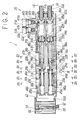
- Fig. 2 is a sectional view of the spacer type pressure reducing valve of the first embodiment of the invention.
- Fig. 3 (a) is a sectional view taken along arrows III a - III a in Fig. 2, (b) is a sectional view taken along arrows III b - III b in Fig. 2, (c) is a sectional view taken along arrows III c - III c in Fig. 2, (d) is a sectional view taken along arrows III d - III d in Fig. 2, (e) is a sectional view taken along arrows III e - III e in Fig. 2, and (f) is a sectional view taken along arrows III f - III f in Fig. 2.
- Fig. 4 is a perspective view of a valve body of the spacer type pressure reducing valve of the first embodiment of the invention.
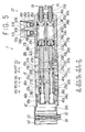
- Fig. 5 is a sectional view of a spacer type pressure reducing valve of a second embodiment of the invention.
- Fig. 6 (a) is a sectional view taken along arrows VI a - VI a in Fig. 5, (b) is a sectional view taken along arrows VI b - VI b in Fig. 5, (c) is a sectional view taken along arrows VI c - VI c in Fig. 5, (d) is a sectional view taken along arrows VI d - VI d in Fig. 5, (e) is a sectional view taken along arrows VI e - VI e in Fig. 5, (f) is a sectional view taken along arrows VI f - VI f in Fig. 5 and (g) is a sectional view taken along arrows VI g - VI g in Fig. 5.
- Fig. 1 is a sectional view showing a spacer type pressure reducing valve of a first embodiment of the invention mounted between a base and solenoid valve.
- Fig. 2 is a sectional view for explaining details of the spacer type pressure reducing valve of the first embodiment.
- Figs. 3(a) to (f) are sectional views taken along positions III a - III a to III f - III f in Fig. 2.
- Fig. 4 is a perspective view of a valve body of the first embodiment of the invention.
- Fig. 5 and subsequent drawings show a second embodiment.
- a spacer type pressure reducing valve 1 is directly fixed between a base 2 and a solenoid valve 3 which is a switching valve by means of mounting means (not shown) such as mounting bolts or the like.
- the base 2 is a member such as a manifold or sub-plate having a piping port, and capable of having one or more solenoid valves therein.
- the illustrated base 2 is a single type base having one solenoid valve 3.
- the base 2 includes a supply flow passage P, a first discharge flow-passage EA and a second discharge flow-passage EB for pressurized fluid (compressed air) formed such as to pass through the base 2.
- the base 2 is formed with a first output port A and a second output port B opening at other side surface.
- the base 2 is provided at its upper surface with a mounting surface 2a for a flat pressure reducing valve.
- a first output communication hole 6A and a second output communication hole 6B, a first discharge communication hole 7A and a second discharge communication hole 7B are opened in single file.
- the solenoid valve 3 is a single or double type electromagnetically actuated switching valve having a main valve portion 8 and a pilot valve portion 9.
- the main valve portion 8 has a flat mounting surface 4a formed on a lower surface of the valve body 4.
- a supply communication hole 10, a first output communication hole 11A and a second output communication hole 11B, a first discharge communication hole 12A and a second discharge communication hole 12B are opened in single file in the mounting surface 4a.
- a valve hole 13 with which the above communication holes are in communication are formed in the valve body 4.
- a valve rod 14 for switching flow-paths is slidably and air-tightly inserted in the valve hole 13.
- pilot fluid in the main valve portion 8 is discharged, the valve rod 14 is returned into a state shown in the drawing by fluid pressure supplied to a chamber opposite from the pilot valve portion 9, thereby switching the state so that the supply communication hole 10 and the second output communication hole 11B are brought into communication with each other and the first output communication hole 11A and the first discharge communication hole 12A are brought into communication with each other.
- the pressure reducing valve 1 includes a thin valve body 15 having rectangular cross section.
- a first pressure-reducing portion 1A and a second pressure-reducing portion 1B are superposed on each other and disposed in the valve body 15.
- Upper and lower surfaces of the valve body 15 are flat mounting surfaces 15a and 15b to which the base 2 and the solenoid valve 3 are to be mounted. By the mounting surfaces 15a and 15b, the pressure reducing valve 1 is directly sandwiched and mounted between the base 2 and the solenoid valve 3.
- the first pressure-reducing portion 1A and the second pressure-reducing portion 1B in the valve body 15 are provided with a plurality of communication passages 16, 17A and 17B, 18A and 18B for connecting communication holes of the solenoid valve 3 and the base 2.
- the communication passages 16, 17A and 17B, 18A and 18B are opened on the upper and lower surfaces 15a and 15b in single file respectively.
- Pressure-adjusting valve holes 19a and 19b that are in parallel to the mounting surface are provided in a direction crossing the communication passages 16, 17A and 17B, 18A and 18B. In thepressure-adjusting valve holes 19a and 19b, pressure-adjusting valve rods 20A and 20B are respectively inserted movably.
- the supplying communication passage 16 among the communication passages 16, 17A, 17B, 18A and 18B for connecting the supply communication hole 5 of the base 2 and the supply communication hole 10 of the solenoid valve 3 with each other is a communication passage which has pressure-adjusting valve seats 25a and 25b and which is capable of opening and closing.
- Outputting communication passages 17A and 17B for connecting first and second output communication holes 6A and 6B and first and second output communication holes 11A and 11B, and discharging communication passages 18A and 18B for connecting first and second discharge communication holes 7A and 7B and first and second discharge communication holes 12A and 12B are direct communication passages for connecting the communication holes straightly.
- the supplying communication passage 16 comprises a first path-portion 16a which is in communication of the supply communication hole 5 on the side of the base 2 and opened at a pressure-adjusting valve hole 19a and a second path-portion 16b which is in communication with the supply communication hole 10 on the side of the solenoid valve 3 and opened at a pressure-adjusting valve hole 19b at a position slightly deviated in a lateral direction from the first path-portion 16a and a third path-portion 16c for bringing the first path-portion 16a and the second path-portion 16b into communication with each other.
- the pressure-adjusting valve seat 25a is provided on a portion of the pressure-adjusting valve hole 19a between the first path-portion 16a and the third path-portion 16c.
- the pressure-adjusting valve seat 25b is provided on a portion of the pressure-adjusting valve hole 19b between the second path-portion 16b and the third path-portion 16c. Opening between the first and third path-portions 16a and 16c, and opening between the second and third path-portions 16b and 16c are adjusted by pressure-adjusting valve bodies 21a and 21b respectively provided on the pressure-adjusting valve rods 20A and 20B.
- the one output communication passage 17A is in communication with the pressure-adjusting valve hole 19b through the pressure intake hole 22A.
- the other output communication passage 17B is in communication with the pressure-adjusting valve hole 19a through the pressure intake hole 22B.
- the pressure-adjusting portion 29 comprises pressure-adjusting chambers 38a and 38b formed between the valve body 15 and the pressure-adjusting side cover 30 such as to be in communication with the pressure-adjusting valve holes 19a and 19b respectively, and pressure-adjusting springs 35a and 35b provided between pressure-adjusting pistons 33a and 33b slidably accommodated in the pressure-adjusting chambers 38a and 38b and spring seats 32a and 32b disposed behind the pressure-adjusting pistons 33a and 33b in the spring chambers 34a and 34b.
- the pressure-adjusting springs 35a and 35b respectively bias the pressure-adjusting pistons 33a and 33b toward the pressure-adjusting valve rods 20A and 20B.
- Spring forces of the pressure-adjusting springs 35a and 35b can be adjusted by rotating adjusting screws 31a and 31b threadedly engauged in the end of the pressure-adjusting side cover 30 forward and backward.
- reference symbols 36a and 36b represent lock nuts for locking the adjusting screws 31a and 31b.
- the pressure-adjusting pistons 33a and 33b are respectively provided with discharge holes 39a and 39b which bring the spring chambers 34a and 34b and breathing holes 40a and 40b formed in the pressure-adjusting side cover 30 into communication with each other to communicate with atmosphere. Ends of the discharge holes 39a and 39b are provided with relief valve members 37a and 37b. Valve-opening/closing portions 41a and 41b formed on tip ends of the pressure-adjusting valve rods 20A and 20B abut against the relief valve members 37a and 37b such that the valve-opening/closing portions 41a and 41b can be in contact or out of contact with respect to the relief valve members 37a and 37b so that the discharge holes 39a and 39b can be opened and closed.
- Returning chambers 45a and 45b are formed on the other end of the valve body 15 between the valve body 15 and the returning-side cover 42.
- returning springs 44a and 44b for biasing the pressure-adjusting valve rods 20A and 20B toward the pressure-adjusting pistons 33a and 33b are respectively provided.
- the biasing force of each of the returning springs 44a and 44b is set smaller than that of each of the pressure-adjusting springs 35a and 35b.
- the returning chambers 45a and 45b are in communication with the pressure-adjusting chambers 38a and 38b through communication flow-passages for introducing pressure-adjusting pressurized fluid into pressure-adjusting chambers and returning chambers on the opposite ends of a pair of pressure-adjusting valve rods 20A and 20B.
- the pressure-adjusting valve rods 20A and 20B have enough outer diameter to be inserted into the pressure-adjusting valve holes 19a and 19b, respectively.
- Pressure-introducing gaps 24a and 24b for communication flow-passages are respectively provided between outer peripheries of the pressure-adjusting valve rods 20A and 20B and the pressure-adjusting valve holes 19a and 19b.
- Pressure-adjusting passages 20a and 20b which are respectively in communication with the returning chambers 45a and 45b are formed in the pressure-adjusting valve rods 20A and 20B.
- the pressure-adjusting passages 20a and 20b form the communication flow-passages together with the pressure-introducing gaps 24a and 24b, and bring the returning chambers 45a and 45b and pressure-adjusting chambers 38a and 38b into communication with each other.
- the communication passage 17A and the returning chamber 45b are in communication with each other through the pressure intake hole 22A and the pressure-introducing gap 24b.
- the communication passage 17B and the pressure-adjusting chamber 38a are in communication with each other through the pressure intake hole 22B and the pressure-introducing gap 24a.
- the pressure-introducing gaps 24a and 24b around the pressure-adjusting valve rods 20A and 20B on the opposite sides of the communication passage 16 are sealed by seal members 46a and 47a and seal members 46b and 47b respectively provided on the pressure-adjusting valve rods 20A and 20B.
- the pressure-adjusting chambers 38a and 38b are in communication with detection ports 43a and 43b provided in pressure-adjusting side cover 30 through connection passages 50a and 50b so that adjusting air pressure of the pressure-adjusting chambers 38a and 38b can be detected by pressure gauges 51a and 51b mounted to the detection ports 43a and 43b.
- the pressure gauges 51a and 51b are disposed in the vicinity of the pair of adjusting screws 31a and 31b so that operability of the adjusting screws 31a and 31b is enhanced.
- a housing 52 is retained and fixed to an end of the returning-side cover 42 through a pawl 52a.
- First and second electric connectors 53 and 55 which are respectively connected to the base 2 and the pilot valve portion 9 of the solenoid valve 3 electrically are provided in the housing 52.
- the first electric connector 53 and the second electric connector 55 are electrically connected to each other through an electric conductor 54.
- the second electric connector 55 is connected to a power source through a feeder line 58.
- Fig. 4 shows opening ends of the communication passages 16, 17A, 17B, 18A and 18B formed in the valve body 15, and a state in which the third path-portion 16c in the communication passage 16 is formed from a side surface of the valve body 15.
- An opening which is necessary to form the third path-portion 16c is sealed by a plate 56 through a gasket 57, or sealed by directly welding the plate 56 to the opening end.
- the pressurized fluid passes through the pressure intake hole 22B and the pressure-introducing gap 24a via the communication passage 17B and is introduced into the pressure-adjusting chamber 38a and at the same time, the pressurized fluid passes through the pressure-adjusting passage 20a and is introduced into the returning chamber 45a.
- the pressure-adjusting valve body 21a opens and closes the pressure-adjusting valve seat 25a with opening in accordance with a difference between a biasing force of the pressure-adjusting spring 35a and a combination force of a fluid pressure acting force acting on the pressure-adjusting piston 33a and a biasing force of the returning spring 44a.
- the communication passage 17A is in communication with the second discharge flow-passage EB through the communication passage 18A. Therefore, pressurized fluid in the pressure-adjusting chamber 38b and the returning chamber 45b flows out from the pressure intake hole 22A into the communication passage 17A through the pressure-introducing gap 24b.
- the pressure-adjusting valve body 21b is maintained in a state in which the pressure-adjusting valve seat 25b is opened by the biasing force of the pressure-adjusting spring 35b.
- the fluid pressure in the output port B is increased to the set pressure, and if the combined force of the fluid pressure acting force acting on the pressure-adjusting piston 33a and the biasing force of the returning spring 44a becomes equal to the biasing force of the pressure-adjusting spring 35a, the pressure-adjusting valve body 21a closes the pressure-adjusting valve seat 25a and thus, the pressure of the pressurized fluid supplied from the supply flow passage P to the second output port B is maintained at the set pressure.
- the pressurized fluid in the pressure-adjusting chamber 38a is discharged outside through the discharge hole 39a and the breathing hole 40a. Therefore, the balance between the fluid pressure acting force and the biasing force of the pressure-adjusting spring 35a is maintained, and the fluid pressure in the second output port B is adjusted to a pressure set by the pressure-adjusting spring 35a.
- the fluid pressure in the second output port B is detected by a pressure gauge 51a mounted in the detection port 43a.
- the fluid pressure is set by threadedly rotating the pressure-adjusting screw 31a to move the same forward or backward to adjust a resilient force of the pressure-adjusting spring 35a.
- the pressurized fluid in the supply flow passage P is introduced into the pressure-adjusting chamber 38b and the returning chamber 45b respectively through the pressure intake hole 22A, the pressure-adjusting passage 20b and the pressure-introducing gap 24b from the communication passage 17A.
- the pressurized fluid in the communication passage 17A is supplied to the fluid pressure device from a first output port A of the base 2.
- the pressure-adjusting valve rod 20B moves leftward, the pressure-adjusting valve body 21b opens the pressure-adjusting valve seat 25b, and the fluid pressure in the first output port A is increased to the set pressure.
- the pressure-adjusting piston 33b moves rightward as viewed in the drawing, the relief valve member 37b is opened, the pressurized fluid in the pressure-adjusting chamber 38b is discharged out through the discharge hole 39b and the breathing holes 40a and 40b, and the fluid pressure in the first output port A is adjusted to a pressure set by the pressure-adjusting spring 35b.
- the fluid pressure of the first output port A is detected by a pressure gauge 51b mounted to the detection port 43b, and setting of the fluid pressure is changed by advancing/retracting the pressure-adjusting screw 31b to adjust the resilient force of the pressure-adjusting spring 35.
- Fig. 5 is a sectional view of a second embodiment of the spacer type pressure reducing valve according to the present invention
- Figs. 6(a) to (g) are sectional views taken along VI a - VI a to VI g - VI g in Fig. 5 positions.
- the communication passage 16 which is in communication with the supply communication hole 10 of the solenoid valve 3 is provided with the pressure-adjusting valve seats 25a and 25b, and their openings are adjusted by the pressure-adjusting valve bodies 21a and 21b.
- a communication passage which is in communication with an output communication hole of the solenoid valve 3 is provided with a pressure-adjusting valve seat and a pressure-adjusting valve body for adjusting its opening.
- a communication passage 17C connecting the first output communication hole 11A of the solenoid valve 3 and the first output port A of the base 2 is brought into communication with the pressure-adjusting valve hole 19b
- the communication passage 17D connecting the second output communication hole 11B the solenoid valve 3 and the second output port B of the base 2 is brought into communication with the pressure-adjusting valve hole 19a
- the communication passages 17C and 17D can function as pressure-adjusting communication passages which are independently opened and closed by the pressure-adjusting valve bodies 21a and 21b and the pressure-adjusting valve seats 25a and 25b
- the communication passage 16 is formed into a direct-communication passage for directly bringing the supply communication hole 10 of the solenoid valve 3 and the supply flow passage P of the base 2 into communication with each other.
- a pressure intake hole 60b for introducing fluid pressure of the communication passage 17C to the pressure-adjusting passage 20b is provided in the pressure-adjusting valve rod 21B.
- a pressure intake hole 60a for introducing the fluid pressure of the communication passage 17D to the pressure-adjusting passage 20a is provided in the pressure-adjusting valve rod 21A.
- the pressure-adjusting pistons 33a and 33b and the pressure-adjusting valve rods 20A and 20B move leftward as viewed in the drawing, and the pressure-adjusting valve bodies 21a and 21b open the pressure-adjusting valve seats 25a and 25b.
- the pressurized fluid is introduced into the pressure-adjusting chamber 38a and the returning chamber 45a through the pressure intake hole 60a, the pressure-adjusting passage 20a and the pressure-introducing gap 24a by the communication passage 17D, and is supplied to the fluid pressure device by the communication passage 17D through the second output port B of the base 2.
- an opening of the pressure-adjusting valve seat 25a is adjusted in accordance with a difference between the biasing force of the pressure-adjusting spring 35a and the combined force of the fluid pressure acting force acting on the pressure-adjusting piston 33a and the returning spring 44a.
- the pressurized fluid supplied to the supply flow passage P is reduced to a pressure set by the pressure-adjusting spring 35a, and is supplied to the second output port B.
- the pressure-adjusting rod 20A moves rightward, the pressure-adjusting valve body 21a closes the pressure-adjusting valve seat 25a, and the fluid pressure of the second output port B is maintained at the set pressure. If the fluid pressure of the communication passage 17D becomes higher than the set pressure in a state in which the pressure-adjusting valve body 21a closed the pressure-adjusting valve seat 25a, the pressure-adjusting piston 33a moves rightward as viewed in the drawing, and the relief valve member 37a is opened.
- the pressurized fluid of the pressure-adjusting chamber 38a is discharged out through the discharge hole 39a and the breathing hole 40a, and the fluid pressure of the second output port B is adjusted to a pressure set by the pressure-adjusting spring 35a.
- the pressurized fluid of the pressure-adjusting chamber 38a and the returning chamber 45a are discharged from the second discharge flow-passage EB through the pressure-adjusting passage 20a, the pressure-introducing gap 24a, the communication passages 17D and 18B, the fluid pressure of the pressure-adjusting chamber 38a and the returning chamber 45a is reduced, and the pressure-adjusting valve body 21a opens the pressure-adjusting valve seat 25a.
- the pressurized fluid from the supply flow passage P is introduced into the pressure-adjusting chamber 38b and the returning chamber 45b through the pressure-adjusting passage 20b and the pressure-introducing gap 24b by the communication passage 17C, and is supplied to the fluid pressure device by the first output port A of the base 2.
- the spacer type pressure reducing valve of each of the above embodiments since the first and second pressure-reducing portion 1A and 1B are disposed in the valve body 15 and the first and second pressure-reducing portion 1A and 1B are integrally formed as one body, the structure is made compactly, and a size thereof can be reduced.
- the spacer type pressure reducing valve since the two pressure-reducing portions are integrally disposed in the valve body, the structure is made compact, and the size thereof can be reduced. Therefore, this is effective for a manifold type in which a plurality of switching valves are mounted in the base. Further, since the pressure gauge is disposed in the vicinity of the adjusting screw, it is possible to enhance the operability of pressure setting of the output port.
Landscapes
- Engineering & Computer Science (AREA)
- Physics & Mathematics (AREA)
- General Engineering & Computer Science (AREA)
- Fluid Mechanics (AREA)
- Mechanical Engineering (AREA)
- General Physics & Mathematics (AREA)
- Automation & Control Theory (AREA)
- Control Of Fluid Pressure (AREA)
- Fluid-Pressure Circuits (AREA)
- Safety Valves (AREA)
Abstract
Description
- The present invention relates to a spacer type pressure reducing valve mounted between a switching valve which switches a direction of flow of pressurised fluid and a base which supplies pressurised fluid to the switching valve, for adjusting output fluid pressures to required valves.
- When a fluid pressure device is actuated by pressurised fluid such as compressed air supplied through a switching valve, it is desirable to adjust the pressure of the fluid to be supplied to the fluid pressure according to a set pressure or actuating state of the device. Therefore, a pressure reducing valve that is a pressure-adjusting valve is usually mounted in a pipe that connects an output port of the switching valve and the fluid pressure device.
- However, since known pressure reducing valves are generally large in size, if the pressure reducing valve is connected to the switching valve by piping, there is a problem that the piping operation is extremely troublesome and large installation space is required.
- This problem is especially prone to arise when a plurality of switching valves are mounted on a base such as a manifold or sub-plate having a piping port, which makes it difficult, in some cases, to mount the pressure reducing valve depending upon the number of switching valves to be used.
- In order to solve the above problems, a spacer type pressure reducing valve has been proposed that is directly sandwiched and mounted between the switching valve and the base, see Japanese Publication Nos. 10-96404, 10-133744 and 10-283037.
- This spacer type pressure reducing valve comprises a valve body having substantially the same lateral width as that of the switching valve, a plurality of communication passages in the valve body which bring communication holes of the switching valve and the base into communication with each other, a pressure-adjusting valve hole cutting across the communication passages, a pressure-adjusting valve rod inserted in the pressure-adjusting valve hole, and means for adjusting air pressure to a set pressure by operation of the pressure-adjusting valve rod. When adjusting pressures in two output ports that are in communication with the fluid pressure device, two spacer type pressure reducing valves are superposed on each other.
- With the above described spacer type pressure reducing valve, when the pressures in two output ports are adjusted, since it is necessary to superpose and use two of the spacer type pressure reducing valves, there are problems that the pressure-reducing portion of the overall assembly becomes large in size and a large installation space is required.
- It is an object of the invention to provide a compact spacer type pressure reducing valve capable of adjusting pressure in two output ports.
- A spacer type pressure reducing valve in accordance with the invention is disposed in use between a switching valve having a supply communication hole, two output communication holes and a discharge communication hole and a base having a plurality of communication holes corresponding to the above communication holes. The spacer type pressure reducing valve comprises a valve body sandwiched in use between the switching valve and the base, the valve body having formed therein two pressure-adjusting valve holes in parallel to each other, two pressure-adjusting valve rods being movably accommodated in the pressure-adjusting valve holes, and a supply communication passage for connecting corresponding supply communication holes in the switching valve and the base, two output communication passages for connecting corresponding output communication holes, and two discharge communication passages for connecting corresponding discharge communication holes. The valve further comprises a pressure-adjusting valve seat and a pressure-adjusting valve body formed in one of the pressure-adjusting valve holes and a pressure-adjusting valve rod therein for adjusting the fluid pressure output from one of the output communication passages, and another pressure-adjusting valve seat and another pressure-adjusting valve body formed in the other pressure-adjusting valve hole and a pressure-adjusting valve rod therein for adjusting fluid pressure output from the other output communication passage. Pressure-adjusting chambers are respectively provided at one end of the two pressure-adjusting valve rods, and returning chambers are respectively provided at the other end of the pressure-adjusting valve rods. The valve includes pressure-adjusting pistons slidably provided in the pressure-adjusting chambers, pressure-adjusting springs for biasing the pressure-adjusting pistons toward the pressure-adjusting valve rods, returning springs respectively provided in the returning chambers for biasing the pressure-adjusting valve rods toward the pressure-adjusting pistons, a communication flow passage for connecting the pressure-adjusting chamber and the returning chamber at the opposite ends of one output communication passage and one pressure-adjusting valve rod, and a communication flow-passage for connecting the pressure-adjusting chamber and the returning chamber at the opposite ends of the other output communication passage and the other pressure-adjusting valve rod.
- Preferably, said pressure-adjusting piston includes a discharge hole for discharging out the pressurised fluid in the pressure-adjusting chamber, and the pressure-adjusting valve rod is provided at its end with an opening/closing portion for opening and closing the discharge hole.
- Moreover, said valve body is provided at its end closer to the pressure-adjusting chamber with two adjusting screws capable of independently adjusting the two pressure-adjusting springs, and two pressure gauges for independently detecting fluid pressures of the two pressure-adjusting chambers.
- Further, said communication flow-passage comprises a pressure-adjusting passage formed in the pressure-adjusting valve rod and brought into communication with the returning chamber and a pressure-introducing gap formed between the pressure-adjusting valve hole and the pressure-adjusting valve rod for connecting the pressure-adjusting passage and the pressure-adjusting chamber, and a pressure intake hole is provided for bringing the returning chamber and the pressure-adjusting passage into communication with the output communication passage.
- In one embodiment, said supply communication passage in the valve body extends through portions of the two pressure-adjusting valve holes, and the pressure-adjusting valve seats are formed at positions of the pressure-adjusting valve holes through which the supply communication passage passes.
- In another embodiment, the two output communication passages in the valve body respectively extend through the two pressure-adjusting valve holes, and the pressure-adjusting valve seats are formed at positions of the pressure-adjusting valve holes through which the output communication passages pass.
- With the above described spacer type pressure reducing valve, since the two pressure-reducing portions are integrally disposed in the valve body, the structure can be made compact and the size thereof can be reduced.
- Further, since in the preferred embodiment the pressure gauge is disposed in the vicinity of the adjusting screw, the operability of the pressure setting of the pressurised fluid is enhanced.
- The invention will now be further described by way of example only with reference to the accompanying drawings in which
- Fig. 1 is a sectional view showing a spacer type pressure reducing valve according to a first embodiment of the invention mounted between a base and a solenoid valve.
- Fig. 2 is a sectional view of the spacer type pressure reducing valve of the first embodiment of the invention.
- In Fig. 3, (a) is a sectional view taken along arrows IIIa - IIIa in Fig. 2, (b) is a sectional view taken along arrows IIIb - IIIb in Fig. 2, (c) is a sectional view taken along arrows IIIc - IIIc in Fig. 2, (d) is a sectional view taken along arrows IIId - IIId in Fig. 2, (e) is a sectional view taken along arrows IIIe - IIIe in Fig. 2, and (f) is a sectional view taken along arrows IIIf - IIIf in Fig. 2.
- Fig. 4 is a perspective view of a valve body of the spacer type pressure reducing valve of the first embodiment of the invention.
- Fig. 5 is a sectional view of a spacer type pressure reducing valve of a second embodiment of the invention.
- In Fig. 6, (a) is a sectional view taken along arrows VIa - VIa in Fig. 5, (b) is a sectional view taken along arrows VIb - VIb in Fig. 5, (c) is a sectional view taken along arrows VIc - VIc in Fig. 5, (d) is a sectional view taken along arrows VId - VId in Fig. 5, (e) is a sectional view taken along arrows VIe - VIe in Fig. 5, (f) is a sectional view taken along arrows VIf - VIf in Fig. 5 and (g) is a sectional view taken along arrows VIg - VIg in Fig. 5.
- In describing embodiments of the spacer type pressure valve like parts are identified with like numerals.
- Fig. 1 is a sectional view showing a spacer type pressure reducing valve of a first embodiment of the invention mounted between a base and solenoid valve. Fig. 2 is a sectional view for explaining details of the spacer type pressure reducing valve of the first embodiment. Figs. 3(a) to (f) are sectional views taken along positions IIIa - IIIa to IIIf - IIIf in Fig. 2. Fig. 4 is a perspective view of a valve body of the first embodiment of the invention. Fig. 5 and subsequent drawings show a second embodiment.
- In Fig. 1, a spacer type
pressure reducing valve 1 is directly fixed between a base 2 and a solenoid valve 3 which is a switching valve by means of mounting means (not shown) such as mounting bolts or the like. - The base 2 is a member such as a manifold or sub-plate having a piping port, and capable of having one or more solenoid valves therein. The illustrated base 2 is a single type base having one solenoid valve 3.
- The base 2 includes a supply flow passage P, a first discharge flow-passage EA and a second discharge flow-passage EB for pressurized fluid (compressed air) formed such as to pass through the base 2. The base 2 is formed with a first output port A and a second output port B opening at other side surface.
The base 2 is provided at its upper surface with a mounting surface 2a for a flat pressure reducing valve. In the mounting surface 2a and asupply communication hole 5 being respectively in communication with each flow passage and a port, a firstoutput communication hole 6A and a secondoutput communication hole 6B, a firstdischarge communication hole 7A and a second discharge communication hole 7B are opened in single file. - The solenoid valve 3 is a single or double type electromagnetically actuated switching valve having a main valve portion 8 and a pilot valve portion 9. The main valve portion 8 has a
flat mounting surface 4a formed on a lower surface of the valve body 4. A supply communication hole 10, a first output communication hole 11A and a second output communication hole 11B, a first discharge communication hole 12A and a second discharge communication hole 12B are opened in single file in themounting surface 4a. Avalve hole 13 with which the above communication holes are in communication are formed in the valve body 4. Avalve rod 14 for switching flow-paths is slidably and air-tightly inserted in thevalve hole 13. - In the illustrated solenoid valve 3, if pilot pressure is output from the pilot valve portion 9 to the main valve portion 8 by excitation of solenoid, the
valve rod 14 moves rightward as viewed in the drawing, the supply communication hole 10 and the first output communication hole 11A are brought into communication with each other, and the second output communication hole 11B and the second discharge communication hole 12B are brought into communication with each other. If the excitation of solenoid is released, pilot fluid in the main valve portion 8 is discharged, thevalve rod 14 is returned into a state shown in the drawing by fluid pressure supplied to a chamber opposite from the pilot valve portion 9, thereby switching the state so that the supply communication hole 10 and the second output communication hole 11B are brought into communication with each other and the first output communication hole 11A and the first discharge communication hole 12A are brought into communication with each other. - In Figs. 2 to 4, the
pressure reducing valve 1 includes athin valve body 15 having rectangular cross section. A first pressure-reducingportion 1A and a second pressure-reducing portion 1B are superposed on each other and disposed in thevalve body 15. Upper and lower surfaces of thevalve body 15 areflat mounting surfaces 15a and 15b to which the base 2 and the solenoid valve 3 are to be mounted. By themounting surfaces 15a and 15b, thepressure reducing valve 1 is directly sandwiched and mounted between the base 2 and the solenoid valve 3. - The first pressure-reducing
portion 1A and the second pressure-reducing portion 1B in thevalve body 15 are provided with a plurality ofcommunication passages communication passages lower surfaces 15a and 15b in single file respectively. Pressure-adjustingvalve holes communication passages valve holes valve rods - The supplying
communication passage 16 among thecommunication passages supply communication hole 5 of the base 2 and the supply communication hole 10 of the solenoid valve 3 with each other is a communication passage which has pressure-adjustingvalve seats Outputting communication passages output communication holes communication passages discharge communication holes 7A and 7B and first and second discharge communication holes 12A and 12B are direct communication passages for connecting the communication holes straightly. - The supplying
communication passage 16 comprises a first path-portion 16a which is in communication of thesupply communication hole 5 on the side of the base 2 and opened at a pressure-adjustingvalve hole 19a and a second path-portion 16b which is in communication with the supply communication hole 10 on the side of the solenoid valve 3 and opened at a pressure-adjustingvalve hole 19b at a position slightly deviated in a lateral direction from the first path-portion 16a and a third path-portion 16c for bringing the first path-portion 16a and the second path-portion 16b into communication with each other. The pressure-adjustingvalve seat 25a is provided on a portion of the pressure-adjustingvalve hole 19a between the first path-portion 16a and the third path-portion 16c. The pressure-adjustingvalve seat 25b is provided on a portion of the pressure-adjustingvalve hole 19b between the second path-portion 16b and the third path-portion 16c. Opening between the first and third path-portions portions 16b and 16c are adjusted by pressure-adjustingvalve bodies valve rods - The one
output communication passage 17A is in communication with the pressure-adjustingvalve hole 19b through thepressure intake hole 22A. The otheroutput communication passage 17B is in communication with the pressure-adjustingvalve hole 19a through thepressure intake hole 22B. - One end of the
valve body 15 is formed with a pressure-adjustingportion 29. The pressure-adjustingportion 29 comprises pressure-adjustingchambers valve body 15 and the pressure-adjustingside cover 30 such as to be in communication with the pressure-adjustingvalve holes springs pistons chambers spring seats pistons spring chambers springs pistons valve rods springs screws side cover 30 forward and backward. In the drawings,reference symbols - The pressure-adjusting
pistons discharge holes spring chambers holes side cover 30 into communication with each other to communicate with atmosphere. Ends of the discharge holes 39a and 39b are provided with relief valve members 37a and 37b. Valve-opening/closing portions 41a and 41b formed on tip ends of the pressure-adjustingvalve rods - Returning
chambers valve body 15 between thevalve body 15 and the returning-side cover 42. In the returningchambers springs valve rods pistons springs springs chambers chambers valve rods - The pressure-adjusting
valve rods valve holes gaps valve rods valve holes - Pressure-adjusting
passages chambers valve rods passages gaps chambers chambers - The
communication passage 17A and the returningchamber 45b are in communication with each other through thepressure intake hole 22A and the pressure-introducinggap 24b. Thecommunication passage 17B and the pressure-adjustingchamber 38a are in communication with each other through thepressure intake hole 22B and the pressure-introducinggap 24a. - The pressure-introducing
gaps valve rods communication passage 16 are sealed byseal members seal members valve rods - The pressure-adjusting
chambers detection ports side cover 30 throughconnection passages chambers pressure gauges detection ports pressure gauges screws - A
housing 52 is retained and fixed to an end of the returning-side cover 42 through apawl 52a. First and secondelectric connectors housing 52. The firstelectric connector 53 and the secondelectric connector 55 are electrically connected to each other through anelectric conductor 54. The secondelectric connector 55 is connected to a power source through afeeder line 58. - Fig. 4 shows opening ends of the
communication passages valve body 15, and a state in which the third path-portion 16c in thecommunication passage 16 is formed from a side surface of thevalve body 15. An opening which is necessary to form the third path-portion 16c is sealed by aplate 56 through agasket 57, or sealed by directly welding theplate 56 to the opening end. - Next, operation of the spacer type pressure reducing valve having the above structure will be explained.
- First, when pressurized fluid, e.g., compressed air is not supplied to the supply flow passage P of the base 2, since the biasing forces of the pressure-adjusting
springs springs pistons valve rods valve bodies valve seats portions communication passage 16. - If the pressurized fluid is supplied to the supply flow passage P of the base 2 and the
communication passage 16 of thepressure reducing valve 1 and thecommunication passage 17B are brought into communication with each other through the solenoid valve 3 and thecommunication passage 17A and thecommunication passage 18A are brought into communication with each other, the pressurized fluid passes through thepressure intake hole 22B and the pressure-introducinggap 24a via thecommunication passage 17B and is introduced into the pressure-adjustingchamber 38a and at the same time, the pressurized fluid passes through the pressure-adjustingpassage 20a and is introduced into the returningchamber 45a. Therefore, the pressure-adjustingvalve body 21a opens and closes the pressure-adjustingvalve seat 25a with opening in accordance with a difference between a biasing force of the pressure-adjustingspring 35a and a combination force of a fluid pressure acting force acting on the pressure-adjustingpiston 33a and a biasing force of the returningspring 44a. In this state, thecommunication passage 17A is in communication with the second discharge flow-passage EB through thecommunication passage 18A. Therefore, pressurized fluid in the pressure-adjustingchamber 38b and the returningchamber 45b flows out from thepressure intake hole 22A into thecommunication passage 17A through the pressure-introducinggap 24b. Thus, the pressure-adjustingvalve body 21b is maintained in a state in which the pressure-adjustingvalve seat 25b is opened by the biasing force of the pressure-adjustingspring 35b. - During a time period in which the combined force of the fluid pressure acting force acting on the pressure-adjusting
piston 33a and the biasing force of the returningspring 44a is smaller than the biasing force of the pressure-adjustingspring 35a in a state in which the pressurized fluid from the supply flow passage P is introduced into the pressure-adjustingchamber 38a and the returningchamber 45a, the pressure-adjustingpiston 33a together with the pressure-adjustingrod 20A move leftward, the pressure-adjustingvalve body 21a opens the pressure-adjustingvalve seat 25a, and in accordance with the opening, pressurized fluid is output to the second output port B. The fluid pressure in the output port B is increased to the set pressure, and if the combined force of the fluid pressure acting force acting on the pressure-adjustingpiston 33a and the biasing force of the returningspring 44a becomes equal to the biasing force of the pressure-adjustingspring 35a, the pressure-adjustingvalve body 21a closes the pressure-adjustingvalve seat 25a and thus, the pressure of the pressurized fluid supplied from the supply flow passage P to the second output port B is maintained at the set pressure. - In a state in which the pressure-adjusting
valve body 21a closes the pressure-adjustingvalve seat 25a, if the pressure of the fluid pressure in the second output port B is further increased, and if the fluid pressure acting force acting on the pressure-adjustingpiston 33a from thecommunication passage 17B becomes greater than the biasing force of the pressure-adjustingspring 35a, the pressure-adjustingpiston 33a moves rightward as viewed in the drawing, and the relief valve member 37a is opened. - With this, the pressurized fluid in the pressure-adjusting
chamber 38a is discharged outside through thedischarge hole 39a and thebreathing hole 40a. Therefore, the balance between the fluid pressure acting force and the biasing force of the pressure-adjustingspring 35a is maintained, and the fluid pressure in the second output port B is adjusted to a pressure set by the pressure-adjustingspring 35a. - The fluid pressure in the second output port B is detected by a
pressure gauge 51a mounted in thedetection port 43a. The fluid pressure is set by threadedly rotating the pressure-adjustingscrew 31a to move the same forward or backward to adjust a resilient force of the pressure-adjustingspring 35a. - Next, if the
communication passage 16 of thepressure reducing valve 1 and thecommunication passage 17A are brought into communication with each other through the solenoid valve 3, and thecommunication passage 17B and thecommunication passage 18B are brought into communication with each other, pressurized fluid in the pressure-adjustingchamber 38a and the returningchamber 45a is discharged out from the second discharge flow-passage EB from the pressure-adjustingpassage 20a and the pressure-introducinggap 24a through thepressure intake hole 22B and thecommunication passages - With this, fluid pressure in the pressure-adjusting
chamber 38a and the returningchamber 45a is lowered, the pressure-adjustingrod 20A moves leftward as viewed in the drawing by the biasing force of the pressure-adjustingspring 35a, and the pressure-adjustingvalve body 21a opens the pressure-adjustingvalve seat 25a. - The pressurized fluid in the supply flow passage P is introduced into the pressure-adjusting
chamber 38b and the returningchamber 45b respectively through thepressure intake hole 22A, the pressure-adjustingpassage 20b and the pressure-introducinggap 24b from thecommunication passage 17A. The pressurized fluid in thecommunication passage 17A is supplied to the fluid pressure device from a first output port A of the base 2. - During a time period in which the combined force of the fluid pressure acting force acting on the pressure-adjusting
piston 33b and the biasing force of the returningspring 44b is smaller than the biasing force of the pressure-adjustingspring 35b, the pressure-adjustingvalve rod 20B moves leftward, the pressure-adjustingvalve body 21b opens the pressure-adjustingvalve seat 25b, and the fluid pressure in the first output port A is increased to the set pressure. When the combined force of the fluid pressure acting force acting on the pressure-adjustingpiston 33b and the biasing force of the returningspring 44b becomes greater than the biasing force of the pressure-adjustingspring 35b, the pressure-adjustingvalve rod 20B moves rightward, the pressure-adjustingvalve body 21b closes the pressure-adjustingvalve seat 25b, and the fluid pressure of the first output port A is maintained at the set pressure. - As described above, if the fluid pressure of the first output port A becomes high in the state in which the pressure-adjusting
valve body 21b closed the pressure-adjustingvalve seat 25b, the pressure-adjustingpiston 33b moves rightward as viewed in the drawing, the relief valve member 37b is opened, the pressurized fluid in the pressure-adjustingchamber 38b is discharged out through thedischarge hole 39b and the breathing holes 40a and 40b, and the fluid pressure in the first output port A is adjusted to a pressure set by the pressure-adjustingspring 35b. - The fluid pressure of the first output port A is detected by a
pressure gauge 51b mounted to thedetection port 43b, and setting of the fluid pressure is changed by advancing/retracting the pressure-adjustingscrew 31b to adjust the resilient force of the pressure-adjusting spring 35. - Fig. 5 is a sectional view of a second embodiment of the spacer type pressure reducing valve according to the present invention, and Figs. 6(a) to (g) are sectional views taken along VIa - VIa to VIg - VIg in Fig. 5 positions.
- In the spacer type pressure reducing valve of the first embodiment shown in Figs. 1 to 3, the
communication passage 16 which is in communication with the supply communication hole 10 of the solenoid valve 3 is provided with the pressure-adjustingvalve seats valve bodies - That is, in this second embodiment, a
communication passage 17C connecting the first output communication hole 11A of the solenoid valve 3 and the first output port A of the base 2 is brought into communication with the pressure-adjustingvalve hole 19b, and the communication passage 17D connecting the second output communication hole 11B the solenoid valve 3 and the second output port B of the base 2 is brought into communication with the pressure-adjustingvalve hole 19a, so that thecommunication passages 17C and 17D can function as pressure-adjusting communication passages which are independently opened and closed by the pressure-adjustingvalve bodies valve seats communication passage 16 is formed into a direct-communication passage for directly bringing the supply communication hole 10 of the solenoid valve 3 and the supply flow passage P of the base 2 into communication with each other. In acommunication passage 17C extending from the pressure-adjustingvalve seat 25b to the first output port A of the base 2, apressure intake hole 60b for introducing fluid pressure of thecommunication passage 17C to the pressure-adjustingpassage 20b is provided in the pressure-adjusting valve rod 21B. In a communication passage 17D extending from the pressure-adjustingvalve seat 25a to the second output port B of the base 2, apressure intake hole 60a for introducing the fluid pressure of the communication passage 17D to the pressure-adjustingpassage 20a is provided in the pressure-adjusting valve rod 21A. - Other structure is the same as that of the spacer type pressure reducing valve shown in Fig. 2 and thus, detailed explanation will be omitted.
- In the spacer type pressure reducing valve of the second embodiment, like the first embodiment, when the pressurized fluid is not supplied to the supply flow passage P of the base 2, the pressure-adjusting
pistons valve rods valve bodies valve seats - If the
communication passages 16 and 17d of thepressure reducing valve 1 are brought into communication with each other and thecommunication passages chamber 38a and the returningchamber 45a through thepressure intake hole 60a, the pressure-adjustingpassage 20a and the pressure-introducinggap 24a by the communication passage 17D, and is supplied to the fluid pressure device by the communication passage 17D through the second output port B of the base 2. - In this case, an opening of the pressure-adjusting
valve seat 25a is adjusted in accordance with a difference between the biasing force of the pressure-adjustingspring 35a and the combined force of the fluid pressure acting force acting on the pressure-adjustingpiston 33a and the returningspring 44a. The pressurized fluid supplied to the supply flow passage P is reduced to a pressure set by the pressure-adjustingspring 35a, and is supplied to the second output port B. - If the combined force of the fluid pressure acting force acting on the pressure-adjusting
piston 33a and the returningspring 44a becomes greater than the biasing force of the pressure-adjustingspring 35a, the pressure-adjustingrod 20A moves rightward, the pressure-adjustingvalve body 21a closes the pressure-adjustingvalve seat 25a, and the fluid pressure of the second output port B is maintained at the set pressure. If the fluid pressure of the communication passage 17D becomes higher than the set pressure in a state in which the pressure-adjustingvalve body 21a closed the pressure-adjustingvalve seat 25a, the pressure-adjustingpiston 33a moves rightward as viewed in the drawing, and the relief valve member 37a is opened. - With this, the pressurized fluid of the pressure-adjusting
chamber 38a is discharged out through thedischarge hole 39a and thebreathing hole 40a, and the fluid pressure of the second output port B is adjusted to a pressure set by the pressure-adjustingspring 35a. - Next, if the
communication passages pressure reducing valve 1 are brought into communication with each other and thecommunication passages 17D and 18B are brought into communication with each other by the solenoid valve 3, the pressurized fluid of the pressure-adjustingchamber 38a and the returningchamber 45a are discharged from the second discharge flow-passage EB through the pressure-adjustingpassage 20a, the pressure-introducinggap 24a, thecommunication passages 17D and 18B, the fluid pressure of the pressure-adjustingchamber 38a and the returningchamber 45a is reduced, and the pressure-adjustingvalve body 21a opens the pressure-adjustingvalve seat 25a. - The pressurized fluid from the supply flow passage P is introduced into the pressure-adjusting
chamber 38b and the returningchamber 45b through the pressure-adjustingpassage 20b and the pressure-introducinggap 24b by thecommunication passage 17C, and is supplied to the fluid pressure device by the first output port A of the base 2. - If the combined force of the fluid pressure acting force acting on the pressure-adjusting
piston 33b and the returningspring 44b becomes greater than the biasing force of the pressure-adjustingspring 35b, the pressure-adjustingrod 20B moves rightward, the pressure-adjustingvalve body 21b closes the pressure-adjustingvalve seat 25b, and the fluid pressure of the first output port A is maintained at the set pressure. - If high fluid pressure flows into the
communication passage 17C in a state in which the pressure-adjustingvalve body 21b closed the pressure-adjustingvalve seat 25b, the pressure-adjustingpiston 33b moves rightward as viewed in the drawing, the relief valve member 37b is opened, the pressurized fluid of the pressure-adjustingchamber 38b is discharged out through thedischarge hole 39b and thebreathing hole 40a, and the fluid pressure of the first output port A is adjusted to a pressure set by the pressure-adjustingspring 35b. - In the spacer type pressure reducing valve of each of the above embodiments, since the first and second pressure-reducing
portion 1A and 1B are disposed in thevalve body 15 and the first and second pressure-reducingportion 1A and 1B are integrally formed as one body, the structure is made compactly, and a size thereof can be reduced. - As will be understood from the above explanation, with the spacer type pressure reducing valve since the two pressure-reducing portions are integrally disposed in the valve body, the structure is made compact, and the size thereof can be reduced. Therefore, this is effective for a manifold type in which a plurality of switching valves are mounted in the base. Further, since the pressure gauge is disposed in the vicinity of the adjusting screw, it is possible to enhance the operability of pressure setting of the output port.
Claims (6)
- A spacer type pressure reducing valve which is disposed in use between a switching valve having a supply communication hole, two output communication holes and a discharge communication hole and a base having a plurality of corresponding communication holes, the spacer type pressure reducing valve comprising a valve body sandwiched in use between the switching valve and the base, two pressure-adjusting valve holes formed in the valve body in parallel to each other, and two pressure-adjusting valve rods movable in the pressure-adjusting valve holes, supply, output and discharge communication passages in the valve body for respectively connecting corresponding supply, output and discharge communication holes of the switching valve and the base, a pressure-adjusting valve seat and a pressure-adjusting valve body formed in each of the pressure-adjusting valve holes and a pressure-adjusting valve rod therein for adjusting the fluid pressure output from the output communication passages, a pressure-adjusting chamber at one end of each pressure-adjusting valve rod, and a returning chamber at the other end of the pressure-adjusting valve rods, a pressure-adjusting piston slidable in each pressure-adjusting chamber, a pressure adjusting spring for biasing each pressure-adjusting piston toward the associated pressure-adjusting valve rod, a returning spring in each returning chamber for biasing the respective pressure-adjusting valve rod toward the associated pressure-adjusting piston, a communication flow-passage for connecting the pressure-adjusting chamber and the returning chamber on the opposite ends of the one pressure-adjusting valve rod, and a communication flow-passage for connecting the pressure-adjusting chamber and the returning chamber on the opposite ends of the other pressure-adjusting valve rod.
- A spacer type pressure reducing valve according to claim 1 wherein the pressure-adjusting piston includes a discharge hole for discharging pressurised fluid in the pressure-adjusting chamber, and the pressure-adjusting valve rod is provided at its end with an opening/closing portion for opening and closing the discharge hole.
- A spacer type pressure reducing valve according to either claim 1 or claim 2 wherein the valve body is provided at the end closer to the pressure-adjusting chambers with two adjusting screws capable of independently adjusting the two pressure-adjusting springs, and two pressure gauges for independently detecting fluid pressure in the two pressure-adjusting chambers.
- A spacer type pressure reducing valve according to any preceding claim wherein the communication flow-passage comprises a pressure-adjusting passage formed in the pressure-adjusting valve rod and in communication with the returning chamber and a pressure-introducing gap formed between the pressure-adjusting valve hole and the pressure-adjusting valve rod for connecting the pressure-adjusting passage and the pressure-adjusting chamber, and wherein a pressure intake hole connects the returning chamber and the pressure-adjusting passage to the output communication passage.
- A spacer type pressure reducing valve according to any preceding claim wherein the supply communication passage in the valve body extends through portions of the two pressure-adjusting valve holes, and the pressure-adjusting valve seats are formed at positions of the pressure-adjusting valve holes through which the supply communication passage passes.
- A spacer type pressure reducing valve according to any one of claims 1 to 4 wherein the two output communication passages in the valve body respectively extend through the two pressure-adjusting valve holes, and the pressure-adjusting valve seats are formed at positions of the pressure-adjusting valve holes through which the output communication passages pass.
Applications Claiming Priority (2)
| Application Number | Priority Date | Filing Date | Title |
|---|---|---|---|
| JP2001022003A JP3520261B2 (en) | 2001-01-30 | 2001-01-30 | Spacer type pressure reducing valve |
| JP2001022003 | 2001-01-30 |
Publications (3)
| Publication Number | Publication Date |
|---|---|
| EP1227384A2 true EP1227384A2 (en) | 2002-07-31 |
| EP1227384A3 EP1227384A3 (en) | 2004-02-04 |
| EP1227384B1 EP1227384B1 (en) | 2007-01-03 |
Family
ID=18887473
Family Applications (1)
| Application Number | Title | Priority Date | Filing Date |
|---|---|---|---|
| EP02250382A Expired - Lifetime EP1227384B1 (en) | 2001-01-30 | 2002-01-21 | Spacer type pressure reducing valve |
Country Status (7)
| Country | Link |
|---|---|
| US (1) | US6615867B2 (en) |
| EP (1) | EP1227384B1 (en) |
| JP (1) | JP3520261B2 (en) |
| KR (1) | KR100438637B1 (en) |
| CN (1) | CN1273760C (en) |
| DE (1) | DE60217197T2 (en) |
| TW (1) | TW502796U (en) |
Cited By (1)
| Publication number | Priority date | Publication date | Assignee | Title |
|---|---|---|---|---|
| EP1780421A1 (en) * | 2005-10-26 | 2007-05-02 | Festo Ag & Co. | Valve array |
Families Citing this family (7)
| Publication number | Priority date | Publication date | Assignee | Title |
|---|---|---|---|---|
| US20040025598A1 (en) * | 2000-09-21 | 2004-02-12 | Festo Ag & Co. | Integrated fluid sensing device |
| US6769299B2 (en) * | 2003-01-08 | 2004-08-03 | Fetso Corporation | Integral dual technology flow sensor |
| JP4178395B2 (en) * | 2003-06-02 | 2008-11-12 | Smc株式会社 | Gauge handle type pressure reducing valve |
| US6901794B2 (en) * | 2003-10-16 | 2005-06-07 | Festo Corporation | Multiple technology flow sensor |
| JP2011518397A (en) * | 2008-04-21 | 2011-06-23 | エマーソン プロセス マネージメント レギュレーター テクノロジーズ インコーポレイテッド | Pressure load supply pressure regulator with pressure balance trim |
| CN104246643A (en) * | 2012-03-06 | 2014-12-24 | 费尔查德工业产品公司 | Systems and methods for a three chamber compensation network |
| KR102469215B1 (en) | 2020-11-13 | 2022-11-23 | 주식회사 대동금속스텐공업 | Boundary fence |
Citations (3)
| Publication number | Priority date | Publication date | Assignee | Title |
|---|---|---|---|---|
| EP0840047A2 (en) * | 1996-10-29 | 1998-05-06 | Smc Corporation | Pressure controlling valve to be attached to a base-mounted change valve |
| EP0869418A1 (en) * | 1997-04-03 | 1998-10-07 | Smc Corporation | Pressure regulating valve mounted in base-mounted transfer valve |
| EP1052440A1 (en) * | 1998-12-01 | 2000-11-15 | Hitachi Construction Machinery Co., Ltd. | Control valve |
Family Cites Families (6)
| Publication number | Priority date | Publication date | Assignee | Title |
|---|---|---|---|---|
| JPS5671651A (en) * | 1979-11-15 | 1981-06-15 | Shinei Kogyo Kk | Proportional pressure reducing valve for double brake system |
| JPS6064056A (en) * | 1984-08-06 | 1985-04-12 | Sumitomo Electric Ind Ltd | Deceleration sensing type load responding composite braking pressure control valve |
| JP3769096B2 (en) | 1996-08-01 | 2006-04-19 | Smc株式会社 | Pressure control valve for switching valve |
| TW347882U (en) | 1996-08-01 | 1998-12-11 | Smc Corp | Pressure-control valve mounted on a base-mount selector valve |
| JP3653160B2 (en) | 1997-04-03 | 2005-05-25 | Smc株式会社 | Pressure control valve for switching valve |
| JP4114996B2 (en) * | 1998-05-08 | 2008-07-09 | 株式会社ユタカ | Two-stage pressure reducing pressure regulator |
-
2001
- 2001-01-30 JP JP2001022003A patent/JP3520261B2/en not_active Expired - Fee Related
- 2001-12-26 TW TW090222950U patent/TW502796U/en not_active IP Right Cessation
-
2002
- 2002-01-03 US US10/033,780 patent/US6615867B2/en not_active Expired - Fee Related
- 2002-01-21 DE DE60217197T patent/DE60217197T2/en not_active Expired - Lifetime
- 2002-01-21 EP EP02250382A patent/EP1227384B1/en not_active Expired - Lifetime
- 2002-01-25 KR KR10-2002-0004443A patent/KR100438637B1/en not_active IP Right Cessation
- 2002-01-29 CN CNB02103219XA patent/CN1273760C/en not_active Expired - Fee Related
Patent Citations (3)
| Publication number | Priority date | Publication date | Assignee | Title |
|---|---|---|---|---|
| EP0840047A2 (en) * | 1996-10-29 | 1998-05-06 | Smc Corporation | Pressure controlling valve to be attached to a base-mounted change valve |
| EP0869418A1 (en) * | 1997-04-03 | 1998-10-07 | Smc Corporation | Pressure regulating valve mounted in base-mounted transfer valve |
| EP1052440A1 (en) * | 1998-12-01 | 2000-11-15 | Hitachi Construction Machinery Co., Ltd. | Control valve |
Cited By (1)
| Publication number | Priority date | Publication date | Assignee | Title |
|---|---|---|---|---|
| EP1780421A1 (en) * | 2005-10-26 | 2007-05-02 | Festo Ag & Co. | Valve array |
Also Published As
| Publication number | Publication date |
|---|---|
| JP2002229650A (en) | 2002-08-16 |
| TW502796U (en) | 2002-09-11 |
| CN1369658A (en) | 2002-09-18 |
| KR20020063807A (en) | 2002-08-05 |
| KR100438637B1 (en) | 2004-07-02 |
| EP1227384B1 (en) | 2007-01-03 |
| JP3520261B2 (en) | 2004-04-19 |
| US6615867B2 (en) | 2003-09-09 |
| DE60217197D1 (en) | 2007-02-15 |
| US20020100512A1 (en) | 2002-08-01 |
| EP1227384A3 (en) | 2004-02-04 |
| CN1273760C (en) | 2006-09-06 |
| DE60217197T2 (en) | 2007-10-11 |
Similar Documents
| Publication | Publication Date | Title |
|---|---|---|
| JPH10169818A (en) | Manifold for changeover valve | |
| US6357335B1 (en) | Pneumatic volume booster for valve positioner | |
| KR100294363B1 (en) | Pressure regulating valve for attaching to base mounted conversion valve | |
| KR20150026845A (en) | Five-port switching valve with residual pressure exhaust valve | |
| JP2579202Y2 (en) | Operating valve with pressure compensation valve | |
| US7021332B2 (en) | Hydraulic valve section with reduced bore distortion | |
| EP1227384B1 (en) | Spacer type pressure reducing valve | |
| WO1995025228A1 (en) | Pressure compensating valve and pressure oil supply device using said pressure compensating valve | |
| JPH1047509A (en) | Pilot type selector valve | |
| US6012490A (en) | Pressure controlling valve to be attached to a base-mounted change valve | |
| KR100244540B1 (en) | Pressure-control valve mounted on a base selector valve | |
| JP3524723B2 (en) | Electrically operated valve manifold | |
| US6062260A (en) | Dual piston pilot valve | |
| JP4029417B2 (en) | Pressure regulating valve for solenoid valve assembly and solenoid valve assembly including the same | |
| US6675830B2 (en) | Valve unit capable of monitoring output pressure | |
| KR102403885B1 (en) | valve apparatus and fluid control apparatus | |
| JP2023108096A (en) | solenoid valve manifold | |
| TWI835525B (en) | Electromagnetic valve manifold | |
| JP3021360B2 (en) | Control valve | |
| JP3769096B2 (en) | Pressure control valve for switching valve | |
| KR20000021944A (en) | Flow control valve for compensating pressure | |
| KR20000009715U (en) | Pilot Solenoid Valve | |
| JPH0835565A (en) | Valve plug |
Legal Events
| Date | Code | Title | Description |
|---|---|---|---|
| PUAI | Public reference made under article 153(3) epc to a published international application that has entered the european phase |
Free format text: ORIGINAL CODE: 0009012 |
|
| 17P | Request for examination filed |
Effective date: 20020204 |
|
| AK | Designated contracting states |
Kind code of ref document: A2 Designated state(s): AT BE CH CY DE DK ES FI FR GB GR IE IT LI LU MC NL PT SE TR |
|
| AX | Request for extension of the european patent |
Free format text: AL;LT;LV;MK;RO;SI |
|
| PUAL | Search report despatched |
Free format text: ORIGINAL CODE: 0009013 |
|
| AK | Designated contracting states |
Kind code of ref document: A3 Designated state(s): AT BE CH CY DE DK ES FI FR GB GR IE IT LI LU MC NL PT SE TR |
|
| AX | Request for extension of the european patent |
Extension state: AL LT LV MK RO SI |
|
| RIC1 | Information provided on ipc code assigned before grant |
Ipc: 7F 15B 13/00 B Ipc: 7G 05D 16/10 A Ipc: 7F 16K 11/06 B Ipc: 7F 16K 27/04 B |
|
| 17Q | First examination report despatched |
Effective date: 20040506 |
|
| AKX | Designation fees paid |
Designated state(s): DE FR GB IT |
|
| GRAP | Despatch of communication of intention to grant a patent |
Free format text: ORIGINAL CODE: EPIDOSNIGR1 |
|
| GRAS | Grant fee paid |
Free format text: ORIGINAL CODE: EPIDOSNIGR3 |
|
| GRAA | (expected) grant |
Free format text: ORIGINAL CODE: 0009210 |
|
| AK | Designated contracting states |
Kind code of ref document: B1 Designated state(s): DE FR GB IT |
|
| REG | Reference to a national code |
Ref country code: GB Ref legal event code: FG4D |
|
| REF | Corresponds to: |
Ref document number: 60217197 Country of ref document: DE Date of ref document: 20070215 Kind code of ref document: P |
|
| EN | Fr: translation not filed | ||
| PLBE | No opposition filed within time limit |
Free format text: ORIGINAL CODE: 0009261 |
|
| STAA | Information on the status of an ep patent application or granted ep patent |
Free format text: STATUS: NO OPPOSITION FILED WITHIN TIME LIMIT |
|
| 26N | No opposition filed |
Effective date: 20071005 |
|
| GBPC | Gb: european patent ceased through non-payment of renewal fee |
Effective date: 20070403 |
|
| PG25 | Lapsed in a contracting state [announced via postgrant information from national office to epo] |
Ref country code: IT Free format text: LAPSE BECAUSE OF FAILURE TO SUBMIT A TRANSLATION OF THE DESCRIPTION OR TO PAY THE FEE WITHIN THE PRESCRIBED TIME-LIMIT Effective date: 20070103 Ref country code: GB Free format text: LAPSE BECAUSE OF NON-PAYMENT OF DUE FEES Effective date: 20070403 Ref country code: FR Free format text: LAPSE BECAUSE OF FAILURE TO SUBMIT A TRANSLATION OF THE DESCRIPTION OR TO PAY THE FEE WITHIN THE PRESCRIBED TIME-LIMIT Effective date: 20070824 |
|
| PG25 | Lapsed in a contracting state [announced via postgrant information from national office to epo] |
Ref country code: FR Free format text: LAPSE BECAUSE OF FAILURE TO SUBMIT A TRANSLATION OF THE DESCRIPTION OR TO PAY THE FEE WITHIN THE PRESCRIBED TIME-LIMIT Effective date: 20070103 |
|
| PGFP | Annual fee paid to national office [announced via postgrant information from national office to epo] |
Ref country code: DE Payment date: 20130122 Year of fee payment: 12 |
|
| REG | Reference to a national code |
Ref country code: DE Ref legal event code: R119 Ref document number: 60217197 Country of ref document: DE |
|
| REG | Reference to a national code |
Ref country code: DE Ref legal event code: R119 Ref document number: 60217197 Country of ref document: DE Effective date: 20140801 |
|
| PG25 | Lapsed in a contracting state [announced via postgrant information from national office to epo] |
Ref country code: DE Free format text: LAPSE BECAUSE OF NON-PAYMENT OF DUE FEES Effective date: 20140801 |