EP1227335A2 - Stromversorgungssystem für ROSAR-Transponder einschliesslich Sende- und Empfangsantennen für ROSAR-Einrichtungen - Google Patents
Stromversorgungssystem für ROSAR-Transponder einschliesslich Sende- und Empfangsantennen für ROSAR-Einrichtungen Download PDFInfo
- Publication number
- EP1227335A2 EP1227335A2 EP01124075A EP01124075A EP1227335A2 EP 1227335 A2 EP1227335 A2 EP 1227335A2 EP 01124075 A EP01124075 A EP 01124075A EP 01124075 A EP01124075 A EP 01124075A EP 1227335 A2 EP1227335 A2 EP 1227335A2
- Authority
- EP
- European Patent Office
- Prior art keywords
- power supply
- rosar
- energy
- wind
- supply according
- Prior art date
- Legal status (The legal status is an assumption and is not a legal conclusion. Google has not performed a legal analysis and makes no representation as to the accuracy of the status listed.)
- Withdrawn
Links
Images

Classifications
-
- H—ELECTRICITY
- H02—GENERATION; CONVERSION OR DISTRIBUTION OF ELECTRIC POWER
- H02N—ELECTRIC MACHINES NOT OTHERWISE PROVIDED FOR
- H02N2/00—Electric machines in general using piezoelectric effect, electrostriction or magnetostriction
- H02N2/18—Electric machines in general using piezoelectric effect, electrostriction or magnetostriction producing electrical output from mechanical input, e.g. generators
- H02N2/185—Electric machines in general using piezoelectric effect, electrostriction or magnetostriction producing electrical output from mechanical input, e.g. generators using fluid streams
-
- G—PHYSICS
- G01—MEASURING; TESTING
- G01S—RADIO DIRECTION-FINDING; RADIO NAVIGATION; DETERMINING DISTANCE OR VELOCITY BY USE OF RADIO WAVES; LOCATING OR PRESENCE-DETECTING BY USE OF THE REFLECTION OR RERADIATION OF RADIO WAVES; ANALOGOUS ARRANGEMENTS USING OTHER WAVES
- G01S13/00—Systems using the reflection or reradiation of radio waves, e.g. radar systems; Analogous systems using reflection or reradiation of waves whose nature or wavelength is irrelevant or unspecified
- G01S13/86—Combinations of radar systems with non-radar systems, e.g. sonar, direction finder
-
- G—PHYSICS
- G01—MEASURING; TESTING
- G01S—RADIO DIRECTION-FINDING; RADIO NAVIGATION; DETERMINING DISTANCE OR VELOCITY BY USE OF RADIO WAVES; LOCATING OR PRESENCE-DETECTING BY USE OF THE REFLECTION OR RERADIATION OF RADIO WAVES; ANALOGOUS ARRANGEMENTS USING OTHER WAVES
- G01S13/00—Systems using the reflection or reradiation of radio waves, e.g. radar systems; Analogous systems using reflection or reradiation of waves whose nature or wavelength is irrelevant or unspecified
- G01S13/88—Radar or analogous systems specially adapted for specific applications
- G01S13/89—Radar or analogous systems specially adapted for specific applications for mapping or imaging
- G01S13/90—Radar or analogous systems specially adapted for specific applications for mapping or imaging using synthetic aperture techniques, e.g. synthetic aperture radar [SAR] techniques
- G01S13/904—SAR modes
- G01S13/9082—Rotating SAR [ROSAR]
-
- G—PHYSICS
- G01—MEASURING; TESTING
- G01S—RADIO DIRECTION-FINDING; RADIO NAVIGATION; DETERMINING DISTANCE OR VELOCITY BY USE OF RADIO WAVES; LOCATING OR PRESENCE-DETECTING BY USE OF THE REFLECTION OR RERADIATION OF RADIO WAVES; ANALOGOUS ARRANGEMENTS USING OTHER WAVES
- G01S7/00—Details of systems according to groups G01S13/00, G01S15/00, G01S17/00
- G01S7/02—Details of systems according to groups G01S13/00, G01S15/00, G01S17/00 of systems according to group G01S13/00
-
- H—ELECTRICITY
- H02—GENERATION; CONVERSION OR DISTRIBUTION OF ELECTRIC POWER
- H02K—DYNAMO-ELECTRIC MACHINES
- H02K44/00—Machines in which the dynamo-electric interaction between a plasma or flow of conductive liquid or of fluid-borne conductive or magnetic particles and a coil system or magnetic field converts energy of mass flow into electrical energy or vice versa
-
- B—PERFORMING OPERATIONS; TRANSPORTING
- B64—AIRCRAFT; AVIATION; COSMONAUTICS
- B64C—AEROPLANES; HELICOPTERS
- B64C2230/00—Boundary layer controls
- B64C2230/12—Boundary layer controls by using electromagnetic tiles, fluid ionizers, static charges or plasma
-
- Y—GENERAL TAGGING OF NEW TECHNOLOGICAL DEVELOPMENTS; GENERAL TAGGING OF CROSS-SECTIONAL TECHNOLOGIES SPANNING OVER SEVERAL SECTIONS OF THE IPC; TECHNICAL SUBJECTS COVERED BY FORMER USPC CROSS-REFERENCE ART COLLECTIONS [XRACs] AND DIGESTS
- Y02—TECHNOLOGIES OR APPLICATIONS FOR MITIGATION OR ADAPTATION AGAINST CLIMATE CHANGE
- Y02T—CLIMATE CHANGE MITIGATION TECHNOLOGIES RELATED TO TRANSPORTATION
- Y02T50/00—Aeronautics or air transport
- Y02T50/10—Drag reduction
-
- Y—GENERAL TAGGING OF NEW TECHNOLOGICAL DEVELOPMENTS; GENERAL TAGGING OF CROSS-SECTIONAL TECHNOLOGIES SPANNING OVER SEVERAL SECTIONS OF THE IPC; TECHNICAL SUBJECTS COVERED BY FORMER USPC CROSS-REFERENCE ART COLLECTIONS [XRACs] AND DIGESTS
- Y10—TECHNICAL SUBJECTS COVERED BY FORMER USPC
- Y10S—TECHNICAL SUBJECTS COVERED BY FORMER USPC CROSS-REFERENCE ART COLLECTIONS [XRACs] AND DIGESTS
- Y10S310/00—Electrical generator or motor structure
- Y10S310/80—Piezoelectric polymers, e.g. PVDF
Definitions
- the invention relates to a power supply system for ROSAR transponders including transmit and receive antennas for ROSAR devices, which are integrated in the tip of a helicopter rotor blade according to the features the preamble of claim 1.
- a ROSAR device is known from DE 39 22 086 and DE 43 23 511, which can be used in real time in online mode and in addition to cartography, obstacle warning, mine detection and landing aid also Target reconnaissance, target tracking and missile briefing.
- the ROSAR equipment is used and works at pulse frequency or in FM-CW mode in the cm or mm wavelength range. Builds on this state of the art the present invention.
- the invention has for its object the power supply for a ROSAR transponder, which is integrated in the tip of a helicopter rotor blade the basis of converting aerodynamic energy into electrical energy to enable and to minimize the maintenance effort significantly, no weight and unbalance problems and easy integration the power supply in a flat, slippery electronics (transponder) card to enable.
- the general idea of the invention provides that a wireless ROSAR power supply on the underside of a rotor blade near the tip of the blade is installed and from the existing wind energy electrical energy for the ROSAR transponder delivers. This can now be mechanical, electrical or magnetohydrodynamic way can be realized.
- Such Power supply device can be part of a retrofit concept for ROSAR glued to the helicopter rotor blade or even in the manufacturing process be integrated into the rotor blade, for example by laminating.
- the tapes are coated with a piezoelectric material and at the beginning and end of these ribbons are the electrodes (Fig. 2).
- Another electrodynamic embodiment provides that said Ribbon magnetic layers are applied and a flat coil with one or more turns across, into which when moving an alternating voltage is induced in the magnetic layers of the ribbons becomes.
- Several of these elements are connected in series or in parallel and all elements of these embodiments (coils, channels and tapes) in microsystem technology Manufacturing method manufactured.
- an ionization device in a flat channel through which the wind flows for example a peak ionization device that operates continuously (Direct current) is switched on or off periodically, so that across an intermittent stream of ions is created which is driven by the wind.
- a peak ionization device that operates continuously (Direct current) is switched on or off periodically, so that across an intermittent stream of ions is created which is driven by the wind.
- a magnetic one Facility that divides the intermittent stream into two separate channels (1, 2) directs what is perpendicular, for example, by a magnetic field of a permanent magnet to the ion current device is effected.
- collectors that act as fine-meshed nets or as metal-coated Channel surface are formed. There is one between these collectors AC voltage, which is a current through a connected consumer drives.
- Several elements are connected in series, parallel or mixed. Also these embodiments are produced using microsystems technology.
Landscapes
- Engineering & Computer Science (AREA)
- Remote Sensing (AREA)
- Radar, Positioning & Navigation (AREA)
- Physics & Mathematics (AREA)
- General Physics & Mathematics (AREA)
- Computer Networks & Wireless Communication (AREA)
- Power Engineering (AREA)
- Electromagnetism (AREA)
- Wind Motors (AREA)
- Details Of Aerials (AREA)
- Radar Systems Or Details Thereof (AREA)
- Near-Field Transmission Systems (AREA)
- Toys (AREA)
Abstract
Description
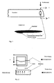
- Fig. 1
- eine Schemaskizze für ein Rotorblatt mit aufgeklebter Stromversorgungskarte,
- Fig. 2
- eine Schemaskizze für ein Ausführungsbeispiel einer aerodynamischelektromagnetischen Ausgestaltung und
- Fig. 3
- einen Querschnitt eines Ausführungsbeispiels für einen aeromagnetohydrodynamischen Generator.
Claims (9)
- Stromversorgung für Sende- und Empfangsantennen eines ROSAR-Systems, die in der Spitze eines Hubschrauber-Rotorblattes integriert sind und in Echtzeitnähe im Online-Betrieb pulsfrequent oder im FM-CW-Betrieb sowie im cm- bzw. mm-Wellenlängenbereich arbeiten, dadurch gekennzeichnet, dass sowohl durch Mini-Turbinengeneratorsätze, die in einem oder mehreren flachen Kanälen, welche durch eine Transponderkarte führen, integriert sind, als auch durch flatternde Bändchen in diesen Kanälen eine piezoelektrische bzw. elektrodynamische Umwandlung der Windenergie in elektrische Energie durchgeführt wird.
- Stromversorgung für Sende- und Empfangsantennen eines ROSAR-Systems, die in der Spitze eines Hubschrauber-Rotorblattes integriert sind und in Echtzeit im Online-Betrieb pulsfrequent oder im FM-CW-Betrieb sowie im cm- bzw. mm-Wellenlängenbereich arbeiten, dadurch gekennzeichnet, dass in einem oder mehreren flachen Kanälen einer Transponderkarte eine elektrische lonisationseinrichtung ein von der Windenergie getriebener lonenstrom erzeugt und mit einem Kollektor aufgefangen wird, wobei Kollektor und lonisierungseinrichtung die Klemmen eines elektrischen Generators bilden zur Umwandlung aerodynamischer in elektrische Energie.
- Stromversorgung für Sende- und Empfangsantennen nach Anspruch 1, dadurch gekennzeichnet, dass sie von in parallel zur Windrichtung angeordneten miniaturisierten turbo-elektrischen Generatoren gebildet wird.
- Stromversorgung nach einem der Ansprüche 1 bis 3, dadurch gekennzeichnet, dass sie als Transponderkarte in ihrer äußeren Form sehr flach und stromlinienförmig konzipiert ist und in ihrer Höhe einen 10 mm-Bereich nicht überschreitet.
- Stromversorgung nach einem der Ansprüche 1 bis 4, dadurch gekennzeichnet, dass die Transponderkarte in zahlreiche Wind-Kanälchen geringer Dimensionierung unterteilt ist, die parallel zur Windrichtung verlaufen, in denen zur Erzeugung einer Flatterenergie entsprechend große Bändchen angeordnet sind, die eine piezoelektrische Schicht aufweisen und an ihrem Anfang und Ende mit Elektroden versehen sind.
- Stromversorgung nach einem der Ansprüche 1 bis 5, dadurch gekennzeichnet, dass die Bändchen mit magnetischen Schichten versehen sind und quer dazu eine Flachspule mit einer oder mehreren Windungen angeordnet ist.
- Stromversorgung nach Anspruch 6, dadurch gekennzeichnet, dass die Bändchen miteinander in Reihe oder parallel geschaltet sind.
- Stromversorgung nach Anspruch 2, dadurch gekennzeichnet, dass sie als flacher vom Wind durchströmter Kanal ausgebildet und mit einer lonisationseinrichtung - vorzugsweise einer Spitzenionisationseinrichtung - versehen ist, die kontinuierlich betrieben (Gleichstrom) oder periodisch (Wechselstrom) ein- und ausgeschaltet wird.
- Stromversorgung nach Anspruch 2 und 8, dadurch gekennzeichnet, dass unmittelbar hinter der lonisationseinrichtung eine magnetische Einrichtung zur Trennung des intermittierenden Stromes in zwei getrennte Kanäle angeordnet ist, denen Kollektoren zugeordnet sind.
Applications Claiming Priority (2)
| Application Number | Priority Date | Filing Date | Title |
|---|---|---|---|
| DE10101989 | 2001-01-18 | ||
| DE10101989A DE10101989C2 (de) | 2001-01-18 | 2001-01-18 | Stromversorgungssystem für ROSAR-Transponder |
Publications (2)
| Publication Number | Publication Date |
|---|---|
| EP1227335A2 true EP1227335A2 (de) | 2002-07-31 |
| EP1227335A3 EP1227335A3 (de) | 2003-01-29 |
Family
ID=7670878
Family Applications (1)
| Application Number | Title | Priority Date | Filing Date |
|---|---|---|---|
| EP01124075A Withdrawn EP1227335A3 (de) | 2001-01-18 | 2001-10-10 | Stromversorgungssystem für ROSAR-Transponder einschliesslich Sende- und Empfangsantennen für ROSAR-Einrichtungen |
Country Status (4)
| Country | Link |
|---|---|
| US (1) | US6677683B2 (de) |
| EP (1) | EP1227335A3 (de) |
| JP (1) | JP3980353B2 (de) |
| DE (1) | DE10101989C2 (de) |
Cited By (3)
| Publication number | Priority date | Publication date | Assignee | Title |
|---|---|---|---|---|
| WO2008111932A1 (en) * | 2007-03-12 | 2008-09-18 | Bell Helicopter Textron Inc. | Rotor blade visual lights |
| EP2003054A1 (de) * | 2007-06-15 | 2008-12-17 | Saab Ab | Vorrichtung zur Stromversorgung |
| US7854590B2 (en) | 2007-03-12 | 2010-12-21 | Bell Helicopter Textron Inc. | Rotor blade visual lights |
Families Citing this family (9)
| Publication number | Priority date | Publication date | Assignee | Title |
|---|---|---|---|---|
| US8004423B2 (en) * | 2004-06-21 | 2011-08-23 | Siemens Energy, Inc. | Instrumented component for use in an operating environment |
| US7368827B2 (en) * | 2006-09-06 | 2008-05-06 | Siemens Power Generation, Inc. | Electrical assembly for monitoring conditions in a combustion turbine operating environment |
| US7969323B2 (en) * | 2006-09-14 | 2011-06-28 | Siemens Energy, Inc. | Instrumented component for combustion turbine engine |
| US8519866B2 (en) | 2007-11-08 | 2013-08-27 | Siemens Energy, Inc. | Wireless telemetry for instrumented component |
| US8797179B2 (en) * | 2007-11-08 | 2014-08-05 | Siemens Aktiengesellschaft | Instrumented component for wireless telemetry |
| US9071888B2 (en) * | 2007-11-08 | 2015-06-30 | Siemens Aktiengesellschaft | Instrumented component for wireless telemetry |
| US9325388B2 (en) | 2012-06-21 | 2016-04-26 | Siemens Energy, Inc. | Wireless telemetry system including an induction power system |
| US9420356B2 (en) | 2013-08-27 | 2016-08-16 | Siemens Energy, Inc. | Wireless power-receiving assembly for a telemetry system in a high-temperature environment of a combustion turbine engine |
| WO2015160656A1 (en) * | 2014-04-16 | 2015-10-22 | Flsmidth A/S | Methods and apparatus for the continuous monitoring of wear in flotation circuits |
Family Cites Families (11)
| Publication number | Priority date | Publication date | Assignee | Title |
|---|---|---|---|---|
| US3206624A (en) * | 1961-08-31 | 1965-09-14 | Theodore P Cotter | Hypersonic plasma thermocouple |
| US3569791A (en) * | 1969-10-22 | 1971-03-09 | Atomic Energy Commission | Remanent-free pulsing magnets |
| US4504761A (en) * | 1981-12-28 | 1985-03-12 | Triplett Charles G | Vehicular mounted piezoelectric generator |
| DE3922086C1 (de) * | 1989-07-05 | 1990-10-18 | Messerschmitt-Boelkow-Blohm Gmbh, 8012 Ottobrunn, De | |
| DE4323511C1 (de) * | 1993-07-14 | 1995-01-26 | Deutsche Aerospace | Radargerät zur Hinderniswarnung |
| US5578877A (en) * | 1994-06-13 | 1996-11-26 | General Electric Company | Apparatus for converting vibratory motion to electrical energy |
| US5637984A (en) * | 1994-10-20 | 1997-06-10 | Nanotechnology, Inc. | Pseudo-mechanical system incorporating ohmic electromechanical transducer and electrical generator |
| US5606247A (en) * | 1995-05-05 | 1997-02-25 | Sundstrand Corporation | Mechanical gear drive system having integral electric power generation capability |
| DE19851910C1 (de) * | 1998-11-11 | 2000-12-07 | Horst Kaltschmidt | Verfahren und Einrichtung zur Durchführung desselben bei einem ROSAR-System |
| US6263736B1 (en) * | 1999-09-24 | 2001-07-24 | Ut-Battelle, Llc | Electrostatically tunable resonance frequency beam utilizing a stress-sensitive film |
| EP1168463A1 (de) * | 2000-06-23 | 2002-01-02 | DORNIER GmbH | Faserverbundwerkstoff mit darin integriertem piezoelektrischem Sensor oder Aktor |
-
2001
- 2001-01-18 DE DE10101989A patent/DE10101989C2/de not_active Expired - Fee Related
- 2001-10-10 EP EP01124075A patent/EP1227335A3/de not_active Withdrawn
- 2001-12-28 JP JP2001399482A patent/JP3980353B2/ja not_active Expired - Lifetime
-
2002
- 2002-01-18 US US10/050,894 patent/US6677683B2/en not_active Expired - Fee Related
Cited By (4)
| Publication number | Priority date | Publication date | Assignee | Title |
|---|---|---|---|---|
| WO2008111932A1 (en) * | 2007-03-12 | 2008-09-18 | Bell Helicopter Textron Inc. | Rotor blade visual lights |
| US7854590B2 (en) | 2007-03-12 | 2010-12-21 | Bell Helicopter Textron Inc. | Rotor blade visual lights |
| EP2003054A1 (de) * | 2007-06-15 | 2008-12-17 | Saab Ab | Vorrichtung zur Stromversorgung |
| US7868477B2 (en) | 2007-06-15 | 2011-01-11 | Saab Ab | Device for supplying electricity |
Also Published As
| Publication number | Publication date |
|---|---|
| EP1227335A3 (de) | 2003-01-29 |
| DE10101989C2 (de) | 2002-12-05 |
| US6677683B2 (en) | 2004-01-13 |
| DE10101989A1 (de) | 2002-08-14 |
| US20020109356A1 (en) | 2002-08-15 |
| JP2003149334A (ja) | 2003-05-21 |
| JP3980353B2 (ja) | 2007-09-26 |
Similar Documents
| Publication | Publication Date | Title |
|---|---|---|
| DE60004831T2 (de) | System zum schutz vor eisbildung und blitzeinschlag für ein windturbinenblatt | |
| EP1282775B1 (de) | Windenergieanlage | |
| EP2828164B1 (de) | Vorrichtung zum erfassen kritischer zustände einer oberfläche | |
| DE1953443C3 (de) | Sendeantennensystem für ein Funkfeuer | |
| DE10101989C2 (de) | Stromversorgungssystem für ROSAR-Transponder | |
| DE509717C (de) | Verfahren zur Bestimmung der Flughoehe von Flugzeugen mittels elektrischer Wellen | |
| DE212017000263U1 (de) | Unbemanntes Luftfahrtzeug | |
| EP2362363A1 (de) | Anlage zum elektrischen Laden von Fahrzeugen | |
| DE102008024644A1 (de) | Rotorblatt mit darin integriertem Radarabsorber für eine Windkraftanlage | |
| WO2005090112A1 (de) | Vorrichtung zur übertragung elektrischer energie vom fahrweg auf das fahrzeug einer magnetschwebebahn | |
| EP2708740A1 (de) | Windenergieanlagenrotorblatt mit einer elektrischen Heizeinrichtung und einem Blitzableiter | |
| DE10231299A1 (de) | Kollisionswarnsystem für Windenergieanlagen | |
| EP1519041A1 (de) | Durch Verkehr angetriebene Windturbinen | |
| DE3390497C2 (de) | Piezoelektrischer Generator zur Entnahme von Energie aus einem Fluidstrom | |
| DE1292205B (de) | Drahtloses Nachrichten-UEbermittlungssystem zur Nachrichtenuebertragung zwischen einem sich entlang einer Spur bewegenden Fahrzeug und einer feststehenden Station | |
| DE3783121T2 (de) | Simulator eines angriffs durch elektromagnetischen puls. | |
| EP0934507B1 (de) | Gleitweg-sendeeinrichtung für das instrumentenlandesystem ils | |
| DE10101991C1 (de) | Verfahren zur Signalverarbeitung- und Prozessierung nach dem ROSAR-System | |
| EP0153436A2 (de) | Tintenstrahldrucker | |
| DE102006013402A1 (de) | Modulares unbemanntes Fluggerät | |
| DE102004027847A1 (de) | Vorrichtung und Verfahren zur induktiven Energieübertragung | |
| DE2363801C3 (de) | Fahrzeugsteuerung | |
| DE102008029441A1 (de) | Elektrische Generierungsvorrichtung und selbstverstärkendes Anregungsverfahren der natürlichen Ladung der Erde | |
| DE102022121282A1 (de) | Schutzvorrichtung zum Entfernen von Eis und/oder Schnee von einer Sensorabdeckung eines Umfeldsensors eines Fahrzeugs, Sensoranordnung sowie Fahrzeug | |
| DE1028632B (de) | Antenne fuer Ultrakurzwellen |
Legal Events
| Date | Code | Title | Description |
|---|---|---|---|
| PUAI | Public reference made under article 153(3) epc to a published international application that has entered the european phase |
Free format text: ORIGINAL CODE: 0009012 |
|
| AK | Designated contracting states |
Kind code of ref document: A2 Designated state(s): AT BE CH CY DE DK ES FI FR GB GR IE IT LI LU MC NL PT SE TR |
|
| AX | Request for extension of the european patent |
Free format text: AL;LT;LV;MK;RO;SI |
|
| RIC1 | Information provided on ipc code assigned before grant |
Free format text: 7G 01S 7/02 A, 7H 01L 41/00 B, 7H 02K 44/00 B, 7G 01S 13/90 B, 7G 01S 13/86 B, 7H 02N 3/00 B |
|
| PUAL | Search report despatched |
Free format text: ORIGINAL CODE: 0009013 |
|
| AK | Designated contracting states |
Designated state(s): AT BE CH CY DE DK ES FI FR GB GR IE IT LI LU MC NL PT SE TR |
|
| AX | Request for extension of the european patent |
Extension state: AL LT LV MK RO SI |
|
| 17P | Request for examination filed |
Effective date: 20030220 |
|
| AKX | Designation fees paid |
Designated state(s): DE FR GB |
|
| 17Q | First examination report despatched |
Effective date: 20040205 |
|
| APBN | Date of receipt of notice of appeal recorded |
Free format text: ORIGINAL CODE: EPIDOSNNOA2E |
|
| APBR | Date of receipt of statement of grounds of appeal recorded |
Free format text: ORIGINAL CODE: EPIDOSNNOA3E |
|
| APAF | Appeal reference modified |
Free format text: ORIGINAL CODE: EPIDOSCREFNE |
|
| APBT | Appeal procedure closed |
Free format text: ORIGINAL CODE: EPIDOSNNOA9E |
|
| STAA | Information on the status of an ep patent application or granted ep patent |
Free format text: STATUS: THE APPLICATION IS DEEMED TO BE WITHDRAWN |
|
| 18D | Application deemed to be withdrawn |
Effective date: 20090505 |