EP1227325A1 - Sensor for speed and vibration - Google Patents
Sensor for speed and vibration Download PDFInfo
- Publication number
- EP1227325A1 EP1227325A1 EP02250503A EP02250503A EP1227325A1 EP 1227325 A1 EP1227325 A1 EP 1227325A1 EP 02250503 A EP02250503 A EP 02250503A EP 02250503 A EP02250503 A EP 02250503A EP 1227325 A1 EP1227325 A1 EP 1227325A1
- Authority
- EP
- European Patent Office
- Prior art keywords
- component
- modulation
- vibration
- disc
- sensor
- Prior art date
- Legal status (The legal status is an assumption and is not a legal conclusion. Google has not performed a legal analysis and makes no representation as to the accuracy of the status listed.)
- Ceased
Links
- 238000001514 detection method Methods 0.000 claims abstract description 22
- 238000000034 method Methods 0.000 claims description 17
- 230000008859 change Effects 0.000 claims description 13
- 230000004044 response Effects 0.000 claims description 6
- 238000001228 spectrum Methods 0.000 claims description 4
- 239000013598 vector Substances 0.000 description 12
- 230000035699 permeability Effects 0.000 description 2
- 230000005355 Hall effect Effects 0.000 description 1
- 230000004075 alteration Effects 0.000 description 1
- 238000013459 approach Methods 0.000 description 1
- 238000001816 cooling Methods 0.000 description 1
- 238000013461 design Methods 0.000 description 1
- 238000006073 displacement reaction Methods 0.000 description 1
- 230000006870 function Effects 0.000 description 1
- 238000012423 maintenance Methods 0.000 description 1
- 230000007257 malfunction Effects 0.000 description 1
- 238000004519 manufacturing process Methods 0.000 description 1
- 239000000463 material Substances 0.000 description 1
- 238000005259 measurement Methods 0.000 description 1
- 238000000691 measurement method Methods 0.000 description 1
- 230000003287 optical effect Effects 0.000 description 1
- 238000013519 translation Methods 0.000 description 1
Images




Classifications
-
- G—PHYSICS
- G01—MEASURING; TESTING
- G01P—MEASURING LINEAR OR ANGULAR SPEED, ACCELERATION, DECELERATION, OR SHOCK; INDICATING PRESENCE, ABSENCE, OR DIRECTION, OF MOVEMENT
- G01P3/00—Measuring linear or angular speed; Measuring differences of linear or angular speeds
- G01P3/42—Devices characterised by the use of electric or magnetic means
- G01P3/44—Devices characterised by the use of electric or magnetic means for measuring angular speed
- G01P3/48—Devices characterised by the use of electric or magnetic means for measuring angular speed by measuring frequency of generated current or voltage
-
- G—PHYSICS
- G01—MEASURING; TESTING
- G01H—MEASUREMENT OF MECHANICAL VIBRATIONS OR ULTRASONIC, SONIC OR INFRASONIC WAVES
- G01H1/00—Measuring characteristics of vibrations in solids by using direct conduction to the detector
- G01H1/003—Measuring characteristics of vibrations in solids by using direct conduction to the detector of rotating machines
- G01H1/006—Measuring characteristics of vibrations in solids by using direct conduction to the detector of rotating machines of the rotor of turbo machines
-
- G—PHYSICS
- G01—MEASURING; TESTING
- G01P—MEASURING LINEAR OR ANGULAR SPEED, ACCELERATION, DECELERATION, OR SHOCK; INDICATING PRESENCE, ABSENCE, OR DIRECTION, OF MOVEMENT
- G01P3/00—Measuring linear or angular speed; Measuring differences of linear or angular speeds
- G01P3/42—Devices characterised by the use of electric or magnetic means
- G01P3/44—Devices characterised by the use of electric or magnetic means for measuring angular speed
- G01P3/48—Devices characterised by the use of electric or magnetic means for measuring angular speed by measuring frequency of generated current or voltage
- G01P3/481—Devices characterised by the use of electric or magnetic means for measuring angular speed by measuring frequency of generated current or voltage of pulse signals
Definitions
- the invention relates to vibration sensing.
- Gas turbine engines are commonly equipped with one, or more, accelerometers to detect vibration. Because the accelerometers sometimes malfunction, back-up accelerometers are often provided. The accelerometers add weight to the engine. They also increase costs of manufacturing, design, and maintenance. Further, some accelerometers are fragile, and easily damaged.
- One form of the invention detects vibration by analyzing an existing pulse train which is produced by an existing sensor, and presently used for speed measurement. Under the invention, the existing pulse train is used to indicate both speed and vibration.
- the invention utilizes a pulse train produced by a sensor. Numerous types of sensor can be used. For simplicity, this discussion will be framed in terms of a generic reluctance sensor.
- Figure 1 illustrates a prior-art system, including a toothed gear 4, a reluctance sensor 8, and an electronic circuit 12.
- the electronic circuit 12 detects passage of each tooth 16 past the reluctance sensor 8.
- the electronic circuit 12 produces a pulse (not shown) in response to each tooth 16, on output 17.
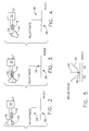
- Reluctance refers to magnetic reluctance. In general, magnetic reluctance depends on (1) the amount, and (2) magnetic permeability, of material located within dashed region 20. For example, tooth 16 in Figure 2 is positioned above a reference line 24. The reluctance seen by sensor 8 is indicated by point 28 in the plot 38.
- tooth 16 in Figure 3 is positioned at the reference 24.
- the reluctance is indicated by point 32.
- tooth 16 in Figure 4 is positioned below the reference 24.
- the reluctance is indicated by point 36.
- a generalized plot 39 of reluctance versus position is given in Figure 5. It is symmetrical about the reference 24, and has a minimum point 40, corresponding to point 32 in Figure 3.
- the electronic circuit 12 does not necessarily measure reluctance itself, but often measures a parameter related to the reluctance.
- Figure 6 shows a hatched tooth 16.
- the hatched tooth 16 passes the sensor 8, and moves to the position shown in Figure 7.
- the electronic circuit 12 produces a signal 41 resembling that in Figure 8. Because of the measurement technique utilized, signal 41 indicates more the slope of the reluctance plot 39 in Figure 5, rather than the reluctance itself.
- the plot of Figure 8 does not exactly indicate the slopes of every point of the plot 39 in Figure 5, but only general features.
- region 48 which is negative, corresponds to region 52 in Figure 5, which has a negative slope.
- a train 72 of pulses 74 is generated, as in Figure 9. If a reluctance sensor is used which measures actual reluctance, as opposed to the slope, then the train of pulses (not shown) will contain a sequence of the plots 39 of Figure 5.
- the pulses 74 within the train 72 in Figure 9 will be identical in shape, and the time intervals 76 between adjacent pulses will be identical.
- the ideal case requires the toothed gear 4 in Figure 7 to be perfectly symmetrical, perfectly homogeneous in magnetic permeability, and rotating at a constant speed about a fixed center 82 in Figure 6.
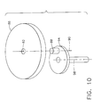
- Disc 86 represents the toothed gear 4 in Figure 6.
- Disc 86 in Figure 10 is supported by shaft 88, and rotates about axis 90. Center 82 is shown.
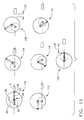
- FIG. 11 illustrates a sequence of positions which the components of Figure 10 will occupy during their combined rotation and orbiting.
- plot 100 indicates the relative arrangement of the components at an initial, reference time.
- Reluctance sensor 8 is shown, as is shaft 88.
- An arm 107 is superimposed, to illustrate the fact that disc 94 acts as a crank arm in supporting shaft 88. Arm 107 rotates about center 98.
- a second arm 105 is shown, to illustrate the fact that disc 86 acts as a crank arm in supporting reference square 106, which represents a tooth 16 of Figure 1.
- arm 105 rotates about shaft 88.
- Figure 11 shows seven plots. Table 1, below, indicates the amount of rotation occurring in each plot. A single amount of rotation is indicated in Table 1 for each plot, because, as stated above, both crank arms 105 and 107 rotate at the same angular speed, although about different centers.
- FIG. 11 (Degrees) 100 zero 104 30 108 60 112 90 116 120 120 150 124 180
- a second feature is that the velocity with which disc 86 passes the reluctance sensor 8 changes as the combined rotation and orbiting occurs.
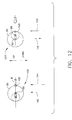
- Figure 12 illustrates this change, and contains copies of plots 100 and 124 from Figure 11. All rotation is counter-clockwise. To simplify the explanation, only the component of velocity in the vertical direction in Figure 12 will be considered. "Up” and “down” are labeled in the center of the Figure.
- vector 140 represents the velocity of shaft 88 in the vertical direction. Since shaft 88 is the axle about which disc 86 rotates, vector 140 also represents the translational velocity of the entire disc 86, in the upward direction. Since reference box 106 is attached to disc 86, vector 140 also represents one velocity component of box 106 in the upward direction.
- vector 144 represents the additional velocity of box 106, due to the rotation of disc 86 about shaft 88.
- the net velocity of box 106 in the upward direction is the vector sum of vectors 140 and 144.
- the net velocity is relatively high, compared with that of plot 124, which will now be considered.
- box 106 has a component of velocity in the upward direction, because of the rotation of disc 86 about shaft 88.
- Vector 152 indicates that component.
- the net velocity of box 106 in the vertical direction is the vector sum of vectors 148 and 152.
- the net velocity is relatively low, compared with that of plot 100, because vectors 148 and 152 for plot 124 oppose each other.
- vibration of disc 86 in Figure 10 can take the form of orbiting of shaft, or center, 88 about axis 98.
- Disc 86 represents the toothed gear 4 of Figure 6. The orbiting causes two events to occur in the parameter measured by the sensor 8 and electronic circuit 12 in Figure 6.
- the orbiting causes a change in the reluctance signal, because the orbiting causes the reluctance seen by sensor 8 to change.
- the second event is that the orbiting changes the tangential speed at which the circumference of disc 86 in Figure 11 passes the sensor 8. Since the teeth 16 in Figure 6 are located at that circumference, their speed will change as orbiting occurs.
- Figures 13 and 15 illustrate how these two events affect the pulse train 72 in Figure 9.
- Figure 13 shows a type of amplitude modulation: the amplitude at point 160 is larger than that at point 164.
- the amplitude change is caused by the movement of disc 86 in Figure 11 toward, and away from, sensor 8.
- the orbiting about center 98 causes the movement. Amplitude is measured from zero to a point such as 160.
- plots 170, 174, 175, and 179 show four successive positions of reference block 165. These four positions are superimposed together in plot 183, and labeled with their corresponding plot numbers.
- Plot 183 indicates that the path of the block 165 is not symmetrical about axis 24. This lack of symmetry is partly responsible for the lack of symmetry in Figure 13, about the zero-amplitude axis 163.
- point 160 in Figure 13 may correspond to the position of block 165 in plot 170 in Figure 14, where reluctance is somewhat high.
- Point 161 in Figure 13 may correspond to the position of block 165 in plot 179 in Figure 14, where reluctance is somewhat low.
- Plot 183 in Figure 14 illustrates the two positions in a single plot, more clearly showing the difference in reluctance.
- Figure 15 shows a type of frequency modulation: the frequency is higher at time 184 than at time 188.
- the higher frequency that is, a smaller time interval between adjacent pulses, would occur in, for example, plot 100 in Figure 11.
- tangential speed is relatively larger, as explained in connection with Figure 12.
- the second change involves the changes in tangential speed of the disc 86.
- the changes in speed causes frequency modulation, as shown in Figure 15.
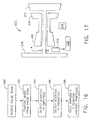
- Figure 16 is a flow chart of logic used to detect the amplitude and frequency modulations shown in Figures 13 and 15.
- Block 190 indicates that the pulse train, such as that of Figure 9, is received.
- the pulse train may, or may not, contain the amplitude modulation or frequency modulation shown in Figures 13 and 15.
- Block 192 in Figure 16 indicates that rotational speed of the toothed gear 4 in Figure 1 is computed. For example, assume that the spacing between gear teeth 16 is ten degrees. If 15 pulses are counted in 0.01 seconds, then rotational speed is computed as (15 x 10) degrees / 0.01 second.
- This quotient corresponds to 15,000 degrees per second, or roughly 41 rpm.
- Block 194 indicates that amplitude modulation is detected. Such detection is well known, and numerous different techniques can be used. As a simple example, the amplitude of each pulse 74 in Figure 9 can be stored in a stack memory. The stack memory may contain 1,000 memory locations. When the stack becomes filled, the earliest amplitudes stored in it become lost.
- amplitudes 1 through 1,000 may be stored in the stack, in sequence. At this time, the stack has become filled. When amplitude 1,001 is added, amplitude 1 becomes lost. When amplitude 1,002 is added, amplitude 2 becomes lost, and so on.
- a detection routine looks for deviations in the amplitudes stored in the stack. As a simple example, the detection routine may scan the stack, and find both the largest amplitude and the smallest amplitude. If the difference between them exceeds a threshold, then unacceptable vibration is inferred.
- Block 196 in Figure 16 indicates that frequency modulation is detected.
- detection is well known, and numerous different techniques can be used.
- a second stack may be used, containing the time intervals between each adjacent pair of the 1,000 amplitudes stored in the first stack.
- a detection routine may scan the second stack, looking for the largest and the smallest interval. If the difference between them exceeds a threshold, then unacceptable vibration is inferred.
- Block 198 indicates that a warning is issued if unacceptable vibration is found.
- a warning signal can be transmitted to the cockpit of an aircraft, if either amplitude modulation or frequency modulation exceeds a limit.
- one goal may be to detect excessive deviation, in frequency and amplitude, of a measured pulse train from an ideal pulse train.
- FFT Fast Fourier Transform
- the pulse train is an ideal pulse train, containing identical pulses, identically spaced, it will have a given distribution of Fourier terms. Further, if the pulses are true sine waves, a single Fourier term will exist.
- Modulation of the pulse train will alter the terms of the Fourier series. If the alteration exceeds a threshold, then unacceptable vibration will be inferred. As a simple example, if the base frequency term, plus the three lowest three harmonics, change by ten percent each, then unacceptable vibration will be inferred. More generally, if any of the first N harmonics change by X percent each, then unacceptable vibration will be inferred.
- FIG 17 illustrates one form of the invention.
- a turbofan aircraft engine 203 is shown, containing a high pressure compressor 200, a high pressure turbine 204, a fan 208, and a low pressure turbine 212.
- Toothed gear 4 is shown, and is used to measure speed of fan 208. Toothed gear 4 need not actually function as a gear, but can be used as a toothed wheel solely to produce pulses.
- Block 216 represents the reluctance sensor and associated electronics, which produces the pulse train 72 of Figure 9.
- the engine control 224 is known in the art. It measures various operating parameters, such as component speeds, airflows, and pressures. Based on those parameters, it schedules, or controls, other parameters, such as fuel-air ratio, blade cooling, and stator vane angle.
- the control 224 contains a microprocessor (not shown) which can perform the computations described in connection with Figure 16.
- a reluctance sensor is not required.
- Other sensors can produce the pulse train of Figure 9, in response to the passage of teeth on a wheel.
- the sensor used should produce pulses of different sizes, when distance to the teeth changes.
- the sensor should also produce pulses, in response to passage of teeth 16 in Figure 1, so that the pulse frequency changes, when the speed of passage of the teeth changes.
- Some examples of sensors are Hall Effect sensors, optical proximity sensors, and microwave proximity sensors.
Landscapes
- Physics & Mathematics (AREA)
- General Physics & Mathematics (AREA)
- Measurement Of Mechanical Vibrations Or Ultrasonic Waves (AREA)
- Transmission And Conversion Of Sensor Element Output (AREA)
Abstract
A vibration detector. A machine, such as a gas turbine engine (203), contains
a rotor (208) bearing a gear (4). A nearby sensor (216) produces a train of
pulses as teeth of the gear (4) travel past. The frequency of the pulse train
indicates rotational speed of the rotor. In addition, vibration of the rotor (208)
causes the gear (4) to orbit about another center. The orbiting causes
amplitude modulation, frequency modulation, or both, in the pulse train.
Detection of the modulation indicates the presence of vibration. Thus, a
single pulse train, produced by a single sensor (216), is used to indicate both
speed, and the presence of vibration.
Description
- The invention relates to vibration sensing.
- Gas turbine engines are commonly equipped with one, or more, accelerometers to detect vibration. Because the accelerometers sometimes malfunction, back-up accelerometers are often provided. The accelerometers add weight to the engine. They also increase costs of manufacturing, design, and maintenance. Further, some accelerometers are fragile, and easily damaged.
- The invention mitigates some, or all, of the disadvantages just identified. One form of the invention detects vibration by analyzing an existing pulse train which is produced by an existing sensor, and presently used for speed measurement. Under the invention, the existing pulse train is used to indicate both speed and vibration.
- An embodiment of the invention will now be described, by way of example, with reference to the accompanying drawings, in which:
- Figure 1 illustrates a
gear 4 and a prior-art reluctance sensor. - Figures 2, 3, and 4 illustrate three different positions of
tooth 16, and the corresponding reluctance seen bysensor 8. - Figure 5 is a plot of reluctance seen by
sensor 8 in Figure 4, plotted against angular position. - Figures 6 and 7 illustrate passage of a
single tooth 16past sensor 8. - Figure 8 illustrates a single pulse, produced by
electronic circuit 12 in Figures 6 and 7, whentooth 16 passes thesensor 8. - Figure 9 illustrates a
pulse train 72, produced byelectronic circuit 12 in Figure 6, when teeth repeatedly pass thesensor 8. - Figure 10 illustrates how vibration of
disc 86, which representsgear 4 in Figure 1, can be represented as orbiting ofshaft 88 aboutaxis 98. - Figure 11 shows several different rotational positions of the apparatus of Figure 10.
- Figure 12 illustrates
plots - Figure 13 illustrates amplitude modulation of the
pulse train 72 of Figure 9. - Figure 14 illustrates how
reference block 165, indicating atooth 16 in Figure 1, follows a non-symmetrical path when orbiting ofdisc 86 occurs, thereby causing the amnplitude modulation of Figure 13. - Figure 15 illustrates frequency modulation of the
pulse train 72 of Figure 9. - Figure 16 is a flow chart illustrating procedures implemented by one form of the invention.
- Figure 17 illustrates one form of the invention.
-
- The invention utilizes a pulse train produced by a sensor. Numerous types of sensor can be used. For simplicity, this discussion will be framed in terms of a generic reluctance sensor.
- Figure 1 illustrates a prior-art system, including a
toothed gear 4, areluctance sensor 8, and anelectronic circuit 12. Theelectronic circuit 12 detects passage of eachtooth 16 past thereluctance sensor 8. Theelectronic circuit 12 produces a pulse (not shown) in response to eachtooth 16, onoutput 17. - "Reluctance" refers to magnetic reluctance. In general, magnetic reluctance depends on (1) the amount, and (2) magnetic permeability, of material located within dashed
region 20. For example,tooth 16 in Figure 2 is positioned above areference line 24. The reluctance seen bysensor 8 is indicated bypoint 28 in theplot 38. - As a second example,
tooth 16 in Figure 3 is positioned at thereference 24. The reluctance is indicated bypoint 32. As a third example,tooth 16 in Figure 4 is positioned below thereference 24. The reluctance is indicated bypoint 36. - A
generalized plot 39 of reluctance versus position is given in Figure 5. It is symmetrical about thereference 24, and has aminimum point 40, corresponding topoint 32 in Figure 3. - The
electronic circuit 12 does not necessarily measure reluctance itself, but often measures a parameter related to the reluctance. For example, Figure 6 shows a hatchedtooth 16. The hatchedtooth 16 passes thesensor 8, and moves to the position shown in Figure 7. In response to this movement, theelectronic circuit 12 produces asignal 41 resembling that in Figure 8. Because of the measurement technique utilized,signal 41 indicates more the slope of thereluctance plot 39 in Figure 5, rather than the reluctance itself. - For simplicity, the plot of Figure 8 does not exactly indicate the slopes of every point of the
plot 39 in Figure 5, but only general features. In Figure 8,region 48, which is negative, corresponds toregion 52 in Figure 5, which has a negative slope.Region 56 in Figure 8, which is positive, corresponds toregion 60 in Figure 5, which has a positive slope.Point 64 in Figure 8, which has a value of zero, corresponds topoint 40 in Figure 5, which has zero slope. - As
successive teeth 16 pass thereluctance sensor 8 in Figure 7, atrain 72 of pulses 74 is generated, as in Figure 9. If a reluctance sensor is used which measures actual reluctance, as opposed to the slope, then the train of pulses (not shown) will contain a sequence of theplots 39 of Figure 5. - In the ideal case, the pulses 74 within the
train 72 in Figure 9 will be identical in shape, and thetime intervals 76 between adjacent pulses will be identical. The ideal case requires thetoothed gear 4 in Figure 7 to be perfectly symmetrical, perfectly homogeneous in magnetic permeability, and rotating at a constant speed about afixed center 82 in Figure 6. - However, if vibration occurs, the ideal case will no longer exist. The
toothed gear 4 will not only rotate about itscenter 82, butcenter 82 will orbit about another center. Figure 10 illustrates the situation.Disc 86 represents thetoothed gear 4 in Figure 6.Disc 86 in Figure 10 is supported byshaft 88, and rotates aboutaxis 90.Center 82 is shown. - In addition, to illustrate the orbiting,
shaft 88 is supported by asecond disc 94.Second disc 94 rotates aboutsecond axis 98. Figure 11 illustrates a sequence of positions which the components of Figure 10 will occupy during their combined rotation and orbiting. - In Figure 11,
plot 100 indicates the relative arrangement of the components at an initial, reference time.Reluctance sensor 8 is shown, as isshaft 88. Anarm 107 is superimposed, to illustrate the fact thatdisc 94 acts as a crank arm in supportingshaft 88.Arm 107 rotates aboutcenter 98. Asecond arm 105 is shown, to illustrate the fact thatdisc 86 acts as a crank arm in supportingreference square 106, which represents atooth 16 of Figure 1. In Figure 11,arm 105 rotates aboutshaft 88. - It is assumed, for simplicity, that both
discs arms - Figure 11 shows seven plots. Table 1, below, indicates the amount of rotation occurring in each plot. A single amount of rotation is indicated in Table 1 for each plot, because, as stated above, both crank
arms - Since they rotate at the same speed, at any given time, their angular displacements from the initial position of
plot 100 will be identical. That is, at any given time, bothcranks PLOT IN TOTAL AMOUNT OF ROTATION FIG. 11 (Degrees) 100 zero 104 30 108 60 112 90 116 120 120 150 124 180 - Two significant features of the combined rotations of Figure 11 are significant. One is that the distance between
disc 86 and thereluctance sensor 8 changes, as the rotations occur. As a specific example,distance 128 inplot 124 is greater thandistance 132 inplot 108. The change in the distance will change the reluctance signal produced bysensor 8. - A second feature is that the velocity with which
disc 86 passes thereluctance sensor 8 changes as the combined rotation and orbiting occurs. Figure 12 illustrates this change, and contains copies ofplots - In
plot 100,vector 140 represents the velocity ofshaft 88 in the vertical direction. Sinceshaft 88 is the axle about whichdisc 86 rotates,vector 140 also represents the translational velocity of theentire disc 86, in the upward direction. Sincereference box 106 is attached todisc 86,vector 140 also represents one velocity component ofbox 106 in the upward direction. - In addition,
vector 144 represents the additional velocity ofbox 106, due to the rotation ofdisc 86 aboutshaft 88. The net velocity ofbox 106 in the upward direction is the vector sum ofvectors plot 124, which will now be considered. - In
plot 124,shaft 88 is now moving downward, becauseshaft 88 rotates counterclockwise aboutshaft 98.Vector 148 indicates its downward component of velocity. Sincedisc 86 is attached toshaft 88,vector 148 also indicates the downward translational velocity of theentire disc 86. Thus,box 106 has a component of velocity in the downward direction, indicated byarrow 148, due to the downward translation ofdisc 86. - In addition,
box 106 has a component of velocity in the upward direction, because of the rotation ofdisc 86 aboutshaft 88.Vector 152 indicates that component. The net velocity ofbox 106 in the vertical direction is the vector sum ofvectors plot 100, becausevectors plot 124 oppose each other. - Therefore, vibration of
disc 86 in Figure 10 can take the form of orbiting of shaft, or center, 88 aboutaxis 98.Disc 86 represents thetoothed gear 4 of Figure 6. The orbiting causes two events to occur in the parameter measured by thesensor 8 andelectronic circuit 12 in Figure 6. - One event is that the orbiting causes a change in the reluctance signal, because the orbiting causes the reluctance seen by
sensor 8 to change. The second event is that the orbiting changes the tangential speed at which the circumference ofdisc 86 in Figure 11 passes thesensor 8. Since theteeth 16 in Figure 6 are located at that circumference, their speed will change as orbiting occurs. - Figures 13 and 15 illustrate how these two events affect the
pulse train 72 in Figure 9. Figure 13 shows a type of amplitude modulation: the amplitude atpoint 160 is larger than that atpoint 164. The amplitude change is caused by the movement ofdisc 86 in Figure 11 toward, and away from,sensor 8. The orbiting aboutcenter 98 causes the movement. Amplitude is measured from zero to a point such as 160. - Most of the pulses shown in Figure 13 are not symmetrical about the zero
amplitude axis 163. The reasons for this are complex, and depend partly on the technique used to produce the pulse train shown in the Figure. However, one factor affecting the lack of symmetry is shown in Figure 14. - In Figure 14,
plots reference block 165. These four positions are superimposed together inplot 183, and labeled with their corresponding plot numbers. -
Plot 183 indicates that the path of theblock 165 is not symmetrical aboutaxis 24. This lack of symmetry is partly responsible for the lack of symmetry in Figure 13, about the zero-amplitude axis 163. For example, in a very general sense,point 160 in Figure 13 may correspond to the position ofblock 165 inplot 170 in Figure 14, where reluctance is somewhat high.Point 161 in Figure 13 may correspond to the position ofblock 165 inplot 179 in Figure 14, where reluctance is somewhat low. Plot 183 in Figure 14 illustrates the two positions in a single plot, more clearly showing the difference in reluctance. - Figure 15 shows a type of frequency modulation: the frequency is higher at
time 184 than attime 188. The higher frequency, that is, a smaller time interval between adjacent pulses, would occur in, for example,plot 100 in Figure 11. Inplot 100, tangential speed is relatively larger, as explained in connection with Figure 12. - A smaller frequency, that is, a larger time interval between adjacent pulses, would occur in
plot 124 of Figure 11. Inplot 124, tangential speed is relatively smaller. - Therefore, two changes occur as the
disc 86 in Figure 10 rotates and orbits. One involves the changes in distance betweendisc 86 in Figure 11 and thesensor 8. These changes cause changes in reluctance. The changes in reluctance cause amplitude modulation of the pulse train, as shown in Figure 13. - The second change involves the changes in tangential speed of the
disc 86. The changes in speed causes frequency modulation, as shown in Figure 15. - Figure 16 is a flow chart of logic used to detect the amplitude and frequency modulations shown in Figures 13 and 15.
Block 190 indicates that the pulse train, such as that of Figure 9, is received. The pulse train may, or may not, contain the amplitude modulation or frequency modulation shown in Figures 13 and 15. -
Block 192 in Figure 16 indicates that rotational speed of thetoothed gear 4 in Figure 1 is computed. For example, assume that the spacing betweengear teeth 16 is ten degrees. If 15 pulses are counted in 0.01 seconds, then rotational speed is computed as - This quotient corresponds to 15,000 degrees per second, or roughly 41 rpm.
-
Block 194 indicates that amplitude modulation is detected. Such detection is well known, and numerous different techniques can be used. As a simple example, the amplitude of each pulse 74 in Figure 9 can be stored in a stack memory. The stack memory may contain 1,000 memory locations. When the stack becomes filled, the earliest amplitudes stored in it become lost. - As a specific example,
amplitudes 1 through 1,000 may be stored in the stack, in sequence. At this time, the stack has become filled. When amplitude 1,001 is added,amplitude 1 becomes lost. When amplitude 1,002 is added, amplitude 2 becomes lost, and so on. - A detection routine looks for deviations in the amplitudes stored in the stack. As a simple example, the detection routine may scan the stack, and find both the largest amplitude and the smallest amplitude. If the difference between them exceeds a threshold, then unacceptable vibration is inferred.
-
Block 196 in Figure 16 indicates that frequency modulation is detected. Such detection is well known, and numerous different techniques can be used. As a simple example, a second stack may be used, containing the time intervals between each adjacent pair of the 1,000 amplitudes stored in the first stack. A detection routine may scan the second stack, looking for the largest and the smallest interval. If the difference between them exceeds a threshold, then unacceptable vibration is inferred. -
Block 198 indicates that a warning is issued if unacceptable vibration is found. For example, a warning signal can be transmitted to the cockpit of an aircraft, if either amplitude modulation or frequency modulation exceeds a limit. - Alternately, numerical values indicating the amount of frequency modulation, and amount of amplitude modulation, can be displayed to an operator, such as a pilot. In communications work, modulation of a carrier is commonly expressed as a percentage, such as fifty percent modulation. This convention can be used by the invention.
- Other, more complex, approaches can be undertaken in detection of the modulations. For example, one goal may be to detect excessive deviation, in frequency and amplitude, of a measured pulse train from an ideal pulse train. To identify the deviation, a Fast Fourier Transform, FFT, of the pulse train is taken.
- If the pulse train is an ideal pulse train, containing identical pulses, identically spaced, it will have a given distribution of Fourier terms. Further, if the pulses are true sine waves, a single Fourier term will exist.
- Modulation of the pulse train, either in amplitude or frequency, will alter the terms of the Fourier series. If the alteration exceeds a threshold, then unacceptable vibration will be inferred. As a simple example, if the base frequency term, plus the three lowest three harmonics, change by ten percent each, then unacceptable vibration will be inferred. More generally, if any of the first N harmonics change by X percent each, then unacceptable vibration will be inferred.
- Figure 17 illustrates one form of the invention. A
turbofan aircraft engine 203 is shown, containing ahigh pressure compressor 200, ahigh pressure turbine 204, afan 208, and alow pressure turbine 212.Toothed gear 4 is shown, and is used to measure speed offan 208.Toothed gear 4 need not actually function as a gear, but can be used as a toothed wheel solely to produce pulses. -
Block 216 represents the reluctance sensor and associated electronics, which produces thepulse train 72 of Figure 9. - The computation indicated by the flow chart of Figure 16 is undertaken by apparatus represented by
block 220 in Figure 17. Alternately, the computation ofblock 220 can be performed by thedigital engine control 224. - The
engine control 224 is known in the art. It measures various operating parameters, such as component speeds, airflows, and pressures. Based on those parameters, it schedules, or controls, other parameters, such as fuel-air ratio, blade cooling, and stator vane angle. Thecontrol 224 contains a microprocessor (not shown) which can perform the computations described in connection with Figure 16. - The discussion herein has been framed in terms of a reluctance sensor. However, a reluctance sensor is not required. Other sensors can produce the pulse train of Figure 9, in response to the passage of teeth on a wheel. The sensor used should produce pulses of different sizes, when distance to the teeth changes. The sensor should also produce pulses, in response to passage of
teeth 16 in Figure 1, so that the pulse frequency changes, when the speed of passage of the teeth changes. Some examples of sensors are Hall Effect sensors, optical proximity sensors, and microwave proximity sensors. - For completeness, various aspects of the invention are set out in the following numbered clauses:
- 1. Method of operating a machine, comprising:
- a) deriving a pulse train from a rotating component; and
- b) using the pulse train to
- i) compute rotational speed of the component; and
- ii) infer vibration in the component.
- 2. Method according to
clause 1, wherein the machine comprises a gas turbine engine. - 3. Method according to
clause 1, wherein the rotating component comprises teeth which sequentially cross a detection region of a sensor. - 4. Method according to clause 3, wherein the sensor produces a train of pulses, vibration of the component causes modulation of the pulses, and the vibration is inferred from the modulation.
- 5. Method according to clause 3, wherein said vibration of the component is inferred from modulation of a train of pulses which is produced by rotation of said component.
- 6. Method, comprising the following steps:
- a) rotating a component in a gas turbine engine, said component containing a disc having teeth distributed along its circumference;
- b) maintaining a sensor near said disc, which produces
- i) one type of pulse when a tooth passes, when the disc is positioned at a first position; and
- ii) a second type of pulse when a tooth passes, when the disc is positioned at a second position;
- c) computing rotational speed of the component, based on frequency of the pulses;
- d) inferring vibration of the component, based on modulation of the pulses.
- 7. Method according to clause 6, wherein vibration of the component causes amplitude modulation of the pulses, and vibration is inferred when the amplitude modulation exceeds a limit.
- 8. Method according to clause 6, wherein vibration of the component causes frequency modulation of the pulses, and vibration is inferred when the frequency modulation exceeds a limit.
- 9. Method according to clause 6, wherein the sensor senses changes in magnetic reluctance caused by passage of the teeth.
- 10. A system comprising:
- a) a gas turbine engine (203) which includes a rotor;
- b) means (216) for producing a train of signals in response to rotation of the rotor;
- c) means (220) for computing rotational speed of the component, based on the train; and
- d) detection means (224) for
- i) searching for modulation of the train, and
- ii) producing a warning signal indicative of the modulation when found.
- 11. System according to
clause 10, wherein the warning signal indicates amount of amplitude modulation. - 12. System according to
clause 10, wherein the warning signal indicates amount of frequency modulation. - 13. System according to
clause 10, wherein the warning signal indicates that modulation exceeds a limit. - 14. System according to
clause 10, wherein the detection means (224) comprises a system for deriving Fourier coefficients of the train. - 15. System according to clause 14, wherein the detection means (224) further comprises a system for detecting changes in the Fourier coefficients.
- 16. A system, comprising:
- a) a gas turbine engine (203), which includes at least one component (208) which is rotatable about an axis (82);
- b) a disc (4)
- i) which has teeth (16) along its circumference
- ii) is attached to said component (208), and
- iii) is concentric about the axis (82);
- c) a sensor (8) which produces a sequence of signals as a sequence of teeth pass; and
- d) detection means (216) for
- i) detecting modulation of said sequence of signals, and
- ii) producing a signal when modulation is detected.
- 17. System according to
clause 16, wherein the detection means (216) detects amplitude modulation. - 18. System according to
clause 17, wherein the detection means (216) detects frequency modulation. - 19. System according to clause 18, wherein the detection means (216) derives a Fourier spectrum from the sequence of signals.
- 20. System according to clause 19, wherein the detection means (216) detects a change in the Fourier spectrum.
-
Claims (10)
- Method of operating a machine, comprising:a) deriving a pulse train from a rotating component; andb) using the pulse train toi) compute rotational speed of the component; andii) infer vibration in the component.
- Method according to claim 1, wherein the rotating component comprises teeth which sequentially cross a detection region of a sensor.
- Method, comprising the following steps:a) rotating a component in a gas turbine engine, said component containing a disc having teeth distributed along its circumference;b) maintaining a sensor near said disc, which producesi) one type of pulse when a tooth passes, when the disc is positioned at a first position; andii) a second type of pulse when a tooth passes, when the disc is positioned at a second position;c) computing rotational speed of the component, based on frequency of the pulses;d) inferring vibration of the component, based on modulation of the pulses.
- Method according to claim 3, wherein vibration of the component causes amplitude or frequency modulation of the pulses, and vibration is inferred when the modulation exceeds a limit.
- A system comprising:a) a gas turbine engine (203) which includes a rotor;b) means (216) for producing a train of signals in response to rotation of the rotor;c) means (220) for computing rotational speed of the component, based on the train; andd) detection means (224) fori) searching for modulation of the train, andii) producing a warning signal indicative of the modulation when found.
- System according to claim 5, wherein the warning signal indicates amount of amplitude or frequency modulation.
- System according to claim 5, wherein the detection means (224) comprises a system for deriving Fourier coefficients of the train, and for detecting changes in the Fourier coefficients.
- A system, comprising:a) a gas turbine engine (203), which includes at least one component (208) which is rotatable about an axis (82);b) a disc (4)i) which has teeth (16) along its circumferenceii) is attached to said component (208), andiii) is concentric about the axis (82);c) a sensor (8) which produces a sequence of signals as a sequence of teeth pass; andd) detection means (216) fori) detecting modulation of said sequence of signals, andii) producing a signal when modulation is detected.
- System according to claim 8, wherein the detection means (216) detects amplitude or frequency modulation,.
- System according to claim 9, wherein the detection means (216) derives a Fourier spectrum from the sequence of signals, and detects a change in the Fourier spectrum.
Applications Claiming Priority (2)
| Application Number | Priority Date | Filing Date | Title |
|---|---|---|---|
| US770326 | 1996-12-20 | ||
| US09/770,326 US6445995B1 (en) | 2001-01-26 | 2001-01-26 | Vibration sensing in gas turbine engine |
Publications (1)
| Publication Number | Publication Date |
|---|---|
| EP1227325A1 true EP1227325A1 (en) | 2002-07-31 |
Family
ID=25088169
Family Applications (1)
| Application Number | Title | Priority Date | Filing Date |
|---|---|---|---|
| EP02250503A Ceased EP1227325A1 (en) | 2001-01-26 | 2002-01-25 | Sensor for speed and vibration |
Country Status (3)
| Country | Link |
|---|---|
| US (1) | US6445995B1 (en) |
| EP (1) | EP1227325A1 (en) |
| JP (1) | JP2002323369A (en) |
Cited By (4)
| Publication number | Priority date | Publication date | Assignee | Title |
|---|---|---|---|---|
| EP1398608A3 (en) * | 2002-09-06 | 2005-02-09 | General Electric Company | High resolution torque measurement on a rotating shaft |
| DE102009009714A1 (en) * | 2009-02-19 | 2010-12-02 | Mtu Aero Engines Gmbh | Device for determining torque at turbine shaft in e.g. aircraft engine, has sensors producing alternating signals, which enable measurement of phase positions and/or processing time, where signal form of signals enable distance measurement |
| RU2428699C1 (en) * | 2010-05-24 | 2011-09-10 | Российская Федерация, от имени которой выступает государственный заказчик - Министерство промышленности и торговли Российской Федерации | Rotation velocity sensor of gas-turbine aircraft engine rotor |
| EP3715821A1 (en) * | 2019-03-29 | 2020-09-30 | Hamilton Sundstrand Corporation | Prognostic monitoring and failure detection of rotating components |
Families Citing this family (34)
| Publication number | Priority date | Publication date | Assignee | Title |
|---|---|---|---|---|
| FR2840358B1 (en) * | 2002-05-28 | 2006-09-15 | Snecma Moteurs | METHOD AND SYSTEM FOR DETECTING ROTOR DAMAGE OF AN AIRCRAFT ENGINE |
| US6909948B2 (en) * | 2003-04-30 | 2005-06-21 | General Electric Company | Accelerometer configuration |
| US6983199B2 (en) * | 2003-04-30 | 2006-01-03 | General Electric Company | Vibration measurement and recording system and method |
| JP2006057817A (en) * | 2004-08-24 | 2006-03-02 | Ntn Corp | Bearing device for wheel with sensor |
| US7253614B2 (en) * | 2005-03-21 | 2007-08-07 | Allegro Microsystems, Inc. | Proximity detector having a sequential flow state machine |
| US7532969B2 (en) * | 2006-03-09 | 2009-05-12 | Pratt & Whitney Canada Corp. | Gas turbine speed detection |
| US20070245746A1 (en) * | 2006-04-21 | 2007-10-25 | Mollmann Daniel E | Methods and systems for detecting rotor assembly speed oscillation in turbine engines |
| US8818683B2 (en) * | 2006-04-21 | 2014-08-26 | General Electric Company | Method and apparatus for operating a gas turbine engine |
| DE102006033461A1 (en) * | 2006-07-19 | 2008-01-31 | Siemens Ag | Radial gap measurement on turbines |
| US8313279B2 (en) * | 2008-04-21 | 2012-11-20 | General Electric Company | Dual rotor vibration monitoring |
| FR2932850B1 (en) * | 2008-06-23 | 2010-08-13 | Snecma | METHOD AND SYSTEM FOR DETERMINING THE ANGULAR POSITION OF A TURBOJET ROTOR |
| US7941281B2 (en) * | 2008-12-22 | 2011-05-10 | General Electric Company | System and method for rotor blade health monitoring |
| JP2010185838A (en) * | 2009-02-13 | 2010-08-26 | Chugoku Electric Power Co Inc:The | Apparatus for detecting shaft vibration of rotating device |
| US8752394B2 (en) * | 2010-03-15 | 2014-06-17 | Rolls-Royce Corporation | Determining fan parameters through pressure monitoring |
| US9574570B2 (en) | 2010-11-03 | 2017-02-21 | Hamilton Sundstard Corporation | Shaft speed and vibration sensor apparatus |
| US8593156B2 (en) | 2010-11-22 | 2013-11-26 | General Electric Company | Sensor assembly and microwave emitter for use in a sensor assembly |
| US8531191B2 (en) | 2010-11-22 | 2013-09-10 | General Electric Company | Sensor assembly and methods of measuring a proximity of a machine component to a sensor |
| US8624603B2 (en) | 2010-11-22 | 2014-01-07 | General Electric Company | Sensor assembly and methods of adjusting the operation of a sensor |
| US8854052B2 (en) | 2010-11-22 | 2014-10-07 | General Electric Company | Sensor assembly and method of measuring the proximity of a machine component to a sensor |
| US8482456B2 (en) | 2010-12-16 | 2013-07-09 | General Electric Company | Sensor assembly and method of measuring the proximity of a machine component to an emitter |
| US9217662B2 (en) | 2011-08-31 | 2015-12-22 | Hamilton Sundstrand Corporation | Vibration signal compensation |
| EP2594946A1 (en) * | 2011-11-18 | 2013-05-22 | Hamilton Sundstrand Corporation | Shaft speed and vibration sensor apparatus |
| US8742319B2 (en) | 2011-12-13 | 2014-06-03 | General Electric Company | Sensor and inspection system deploying an optical conduit |
| US9417258B2 (en) | 2012-09-10 | 2016-08-16 | United Technologies Corporation | Sensor and tooth arrangement for shaft speed detection |
| DE102012222202A1 (en) * | 2012-12-04 | 2014-06-05 | Robert Bosch Gmbh | Method for monitoring a rotation of a compressor wheel |
| AU2014270291B2 (en) | 2013-05-21 | 2016-08-11 | Konecranes Global Corporation | Techniques for monitoring gear condition |
| US9140718B2 (en) | 2013-10-04 | 2015-09-22 | Hamilton Sundstrand Corporation | Speed sensor identification |
| US9840935B2 (en) | 2014-03-31 | 2017-12-12 | United Technologies Corporation | Rotating machinery monitoring system |
| FR3040493B1 (en) * | 2015-08-31 | 2019-06-07 | Safran Landing Systems | METHOD FOR MEASURING THE ROTATION SPEED OF A VEHICLE WHEEL |
| US10228305B2 (en) * | 2016-01-18 | 2019-03-12 | Pratt & Whitney Canada Corp. | Shaft shear detection through shaft oscillation |
| US10228304B2 (en) * | 2016-01-18 | 2019-03-12 | Pratt & Whitney Canada Corp. | Shaft shear detection through shaft oscillation |
| DE102018108827B3 (en) * | 2018-04-13 | 2019-05-29 | Trumpf Schweiz Ag | Method for controlling at least one radial fan in a refrigeration system and radial fan |
| WO2019217635A1 (en) | 2018-05-09 | 2019-11-14 | Abb Schweiz Ag | Turbine speed detection and use |
| GB201904123D0 (en) * | 2019-03-26 | 2019-05-08 | Rolls Royce Plc | Methods of monitoring vibration and trim balance using speed probes |
Citations (5)
| Publication number | Priority date | Publication date | Assignee | Title |
|---|---|---|---|---|
| US3488581A (en) * | 1967-10-03 | 1970-01-06 | Reliance Electric & Eng Co | Surface interruption calibrated non-contact transducer system |
| US3680363A (en) * | 1969-10-07 | 1972-08-01 | Snecma | Devices for detecting and processing vibrations occurring in the moving blades of a rotary compressor or similar apparatus |
| US4482859A (en) * | 1981-05-15 | 1984-11-13 | S.N.E.C.M.A. | Object displacement sensor and device for measuring the rotation speed and vibration frequency of a rotor |
| GB2312958A (en) * | 1996-05-09 | 1997-11-12 | Rotadata Ltd | Method and apparatus for analysing variations in rotary motion |
| EP0980001A1 (en) * | 1998-08-13 | 2000-02-16 | Eaton Corporation | Driveline vibration analyzer |
Family Cites Families (5)
| Publication number | Priority date | Publication date | Assignee | Title |
|---|---|---|---|---|
| US3898439A (en) * | 1970-10-20 | 1975-08-05 | Westinghouse Electric Corp | System for operating industrial gas turbine apparatus and gas turbine electric power plants preferably with a digital computer control system |
| JPS5938422B2 (en) * | 1971-10-15 | 1984-09-17 | ウエスチングハウス・エレクトリツク・コーポレーシヨン | gas turbine power plant |
| US3866108A (en) * | 1971-12-06 | 1975-02-11 | Westinghouse Electric Corp | Control system and method for controlling dual fuel operation of industrial gas turbine power plants, preferably employing a digital computer |
| US5252860A (en) * | 1989-12-11 | 1993-10-12 | Westinghouse Electric Corp. | Gas turbine control system having maximum instantaneous load-pickup limiter |
| US6191513B1 (en) * | 1997-10-27 | 2001-02-20 | Mohawk Innovative Technology, Inc. | Stator-controlled magnetic bearing |
-
2001
- 2001-01-26 US US09/770,326 patent/US6445995B1/en not_active Expired - Lifetime
-
2002
- 2002-01-25 JP JP2002016272A patent/JP2002323369A/en not_active Withdrawn
- 2002-01-25 EP EP02250503A patent/EP1227325A1/en not_active Ceased
Patent Citations (5)
| Publication number | Priority date | Publication date | Assignee | Title |
|---|---|---|---|---|
| US3488581A (en) * | 1967-10-03 | 1970-01-06 | Reliance Electric & Eng Co | Surface interruption calibrated non-contact transducer system |
| US3680363A (en) * | 1969-10-07 | 1972-08-01 | Snecma | Devices for detecting and processing vibrations occurring in the moving blades of a rotary compressor or similar apparatus |
| US4482859A (en) * | 1981-05-15 | 1984-11-13 | S.N.E.C.M.A. | Object displacement sensor and device for measuring the rotation speed and vibration frequency of a rotor |
| GB2312958A (en) * | 1996-05-09 | 1997-11-12 | Rotadata Ltd | Method and apparatus for analysing variations in rotary motion |
| EP0980001A1 (en) * | 1998-08-13 | 2000-02-16 | Eaton Corporation | Driveline vibration analyzer |
Non-Patent Citations (1)
| Title |
|---|
| ANDRENELLI L ET AL: "LARGE-BANDWIDTH REFLECTION FIBER-OPTIC SENSORS FOR TURBOMACHINERY ROTOR BLADE DIAGNOSTICS", SENSORS AND ACTUATORS A, ELSEVIER SEQUOIA S.A., LAUSANNE, CH, vol. A32, no. 1 / 3, 1 April 1992 (1992-04-01), pages 539 - 542, XP000287371, ISSN: 0924-4247 * |
Cited By (6)
| Publication number | Priority date | Publication date | Assignee | Title |
|---|---|---|---|---|
| EP1398608A3 (en) * | 2002-09-06 | 2005-02-09 | General Electric Company | High resolution torque measurement on a rotating shaft |
| KR100831478B1 (en) * | 2002-09-06 | 2008-05-22 | 제너럴 일렉트릭 캄파니 | High resolution torque measurement on a rotating shaft |
| DE102009009714A1 (en) * | 2009-02-19 | 2010-12-02 | Mtu Aero Engines Gmbh | Device for determining torque at turbine shaft in e.g. aircraft engine, has sensors producing alternating signals, which enable measurement of phase positions and/or processing time, where signal form of signals enable distance measurement |
| RU2428699C1 (en) * | 2010-05-24 | 2011-09-10 | Российская Федерация, от имени которой выступает государственный заказчик - Министерство промышленности и торговли Российской Федерации | Rotation velocity sensor of gas-turbine aircraft engine rotor |
| EP3715821A1 (en) * | 2019-03-29 | 2020-09-30 | Hamilton Sundstrand Corporation | Prognostic monitoring and failure detection of rotating components |
| US11148236B2 (en) | 2019-03-29 | 2021-10-19 | Hamilton Sundstrand Corporation | Prognostic monitoring and failure detection of rotating components |
Also Published As
| Publication number | Publication date |
|---|---|
| US6445995B1 (en) | 2002-09-03 |
| JP2002323369A (en) | 2002-11-08 |
Similar Documents
| Publication | Publication Date | Title |
|---|---|---|
| EP1227325A1 (en) | Sensor for speed and vibration | |
| EP0654163B1 (en) | Process and device for monitoring vibrational excitation of an axial compressor | |
| EP0654162B1 (en) | Process for detecting fouling of an axial compressor | |
| US4955269A (en) | Turbine blade fatigue monitor | |
| US4896537A (en) | Shrouded turbine blade vibration monitor | |
| US6904371B2 (en) | Method and apparatus for measuring rotor unbalance | |
| KR100296671B1 (en) | Apparatus and processes for control and monitoring of compressors | |
| JPH0264206A (en) | Method and apparatus for monitoring vibration of turbine blades | |
| US20050122095A1 (en) | Rotation sensor and method | |
| US8497676B2 (en) | Method and system for determining the angular position of a turbojet engine rotor | |
| GB2455798A (en) | Monitoring a rotating shaft in a gas turbine | |
| CA2762744A1 (en) | Determination of a vibrational frequency of a wind turbine rotor blade with a sensor device being placed at a structural component being assigned to and/or being part of the rotor | |
| EP1273763A3 (en) | An apparatus and method for detecting a damaged rotary machine aerofoil | |
| US20180371915A1 (en) | Devices and methods for balancing a high-pressure spool of a gas turbine engine | |
| EP3686606B1 (en) | Shaft monitoring system | |
| WO2003060453A1 (en) | Method and system for balancing a rotating machinery operating at resonance | |
| EP2073020A1 (en) | Method and apparatus for monitoring the rotational speed of the shaft of a gas turbine | |
| CN113139244B (en) | Precursor sensing device and precursor sensing method | |
| Courrech et al. | Condition monitoring of machinery | |
| JP2572530B2 (en) | Vibration spectrum monitoring device, and health monitoring method and device | |
| CN116519121A (en) | Non-contact vibration measuring device and method for rotating blades of complete engine | |
| Murray III et al. | Detection of rotor forced response vibrations using stationary pressure transducers in a multistage axial compressor | |
| RU2229104C1 (en) | Method establishing parameters of vibrations of blades of turbomachines | |
| RU2207524C1 (en) | Method for determining amplitude of oscillations of turbomachine blade | |
| Liska et al. | Measurement and evaluation of shaft torsional vibrations using shaft instantaneous angular velocity |
Legal Events
| Date | Code | Title | Description |
|---|---|---|---|
| PUAI | Public reference made under article 153(3) epc to a published international application that has entered the european phase |
Free format text: ORIGINAL CODE: 0009012 |
|
| AK | Designated contracting states |
Kind code of ref document: A1 Designated state(s): AT BE CH CY DE DK ES FI FR GB GR IE IT LI LU MC NL PT SE TR |
|
| AX | Request for extension of the european patent |
Free format text: AL;LT;LV;MK;RO;SI |
|
| 17P | Request for examination filed |
Effective date: 20030131 |
|
| AKX | Designation fees paid |
Designated state(s): DE FR GB IT |
|
| 17Q | First examination report despatched |
Effective date: 20040927 |
|
| STAA | Information on the status of an ep patent application or granted ep patent |
Free format text: STATUS: THE APPLICATION HAS BEEN REFUSED |
|
| 18R | Application refused |
Effective date: 20061106 |