EP1226998A1 - Auxillary seat for the cab of an industrial vehicle and cab provided with said seat - Google Patents
Auxillary seat for the cab of an industrial vehicle and cab provided with said seat Download PDFInfo
- Publication number
- EP1226998A1 EP1226998A1 EP02001804A EP02001804A EP1226998A1 EP 1226998 A1 EP1226998 A1 EP 1226998A1 EP 02001804 A EP02001804 A EP 02001804A EP 02001804 A EP02001804 A EP 02001804A EP 1226998 A1 EP1226998 A1 EP 1226998A1
- Authority
- EP
- European Patent Office
- Prior art keywords
- seat
- cab
- backrest
- auxiliary
- industrial vehicle
- Prior art date
- Legal status (The legal status is an assumption and is not a legal conclusion. Google has not performed a legal analysis and makes no representation as to the accuracy of the status listed.)
- Granted
Links
- 238000004873 anchoring Methods 0.000 claims description 10
- 230000008878 coupling Effects 0.000 claims description 7
- 238000010168 coupling process Methods 0.000 claims description 7
- 238000005859 coupling reaction Methods 0.000 claims description 7
- 101100494448 Caenorhabditis elegans cab-1 gene Proteins 0.000 description 11
- 230000000694 effects Effects 0.000 description 2
- 230000004048 modification Effects 0.000 description 1
- 238000012986 modification Methods 0.000 description 1
- 230000000284 resting effect Effects 0.000 description 1
- 230000000717 retained effect Effects 0.000 description 1
Images


Classifications
-
- B—PERFORMING OPERATIONS; TRANSPORTING
- B60—VEHICLES IN GENERAL
- B60N—SEATS SPECIALLY ADAPTED FOR VEHICLES; VEHICLE PASSENGER ACCOMMODATION NOT OTHERWISE PROVIDED FOR
- B60N2/00—Seats specially adapted for vehicles; Arrangement or mounting of seats in vehicles
- B60N2/70—Upholstery springs ; Upholstery
- B60N2/7005—Upholstery springs ; Upholstery detachable
-
- B—PERFORMING OPERATIONS; TRANSPORTING
- B60—VEHICLES IN GENERAL
- B60N—SEATS SPECIALLY ADAPTED FOR VEHICLES; VEHICLE PASSENGER ACCOMMODATION NOT OTHERWISE PROVIDED FOR
- B60N2/00—Seats specially adapted for vehicles; Arrangement or mounting of seats in vehicles
- B60N2/005—Arrangement or mounting of seats in vehicles, e.g. dismountable auxiliary seats
-
- B—PERFORMING OPERATIONS; TRANSPORTING
- B60—VEHICLES IN GENERAL
- B60N—SEATS SPECIALLY ADAPTED FOR VEHICLES; VEHICLE PASSENGER ACCOMMODATION NOT OTHERWISE PROVIDED FOR
- B60N2/00—Seats specially adapted for vehicles; Arrangement or mounting of seats in vehicles
- B60N2/75—Arm-rests
-
- B—PERFORMING OPERATIONS; TRANSPORTING
- B60—VEHICLES IN GENERAL
- B60N—SEATS SPECIALLY ADAPTED FOR VEHICLES; VEHICLE PASSENGER ACCOMMODATION NOT OTHERWISE PROVIDED FOR
- B60N2/00—Seats specially adapted for vehicles; Arrangement or mounting of seats in vehicles
- B60N2/90—Details or parts not otherwise provided for
- B60N2/986—Side-rests
-
- B—PERFORMING OPERATIONS; TRANSPORTING
- B62—LAND VEHICLES FOR TRAVELLING OTHERWISE THAN ON RAILS
- B62D—MOTOR VEHICLES; TRAILERS
- B62D33/00—Superstructures for load-carrying vehicles
- B62D33/06—Drivers' cabs
- B62D33/0612—Cabins with living accommodation, especially for long distance road vehicles, i.e. sleeping, cooking, or other facilities
Definitions
- the present invention refers to an auxiliary seat for an industrial vehicle.
- cabs of industrial vehicles are traditionally provided with two seats side by side, one being the main driving seat and the other an auxiliary passenger seat.
- This type of traditional arrangement derives from the habit, which has now been superseded, of using two drivers that take it in turns to drive.
- the trend to use one single driver for each vehicle has become an established practice. It follows that an auxiliary seat for the passenger positioned beside the main seat and basically identical to the latter is unnecessary in the majority of cases and even disadvantageous as it limits the space available inside the cab for recreational activities when the driver is not driving.
- the aim of the present invention is to produce an auxiliary seat for a cab on an industrial vehicle in order to minimise impediments in the cab and permit rational flexible use of the space in the cab itself.
- auxiliary seat for a cab of an industrial vehicle comprising a seat and a backrest, characterised in that said backrest is removable from the seat and is positionable with respect to said seat in at least two different arrangements.
- the invention also relates to a cab for an industrial vehicle, of the type comprising a main driving seat and an auxiliary seat featuring a seat and a backrest, characterised in that the backrest of the auxiliary seat is removable from the seat and is positionable with respect to said seat in at least two different arrangements.
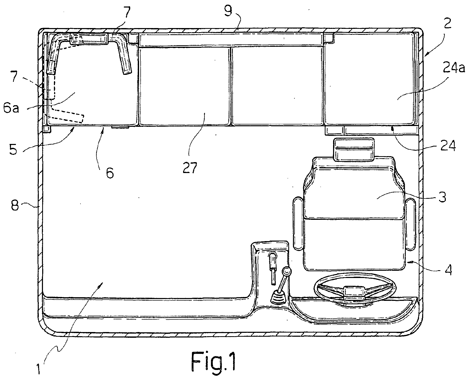
- number 1 indicates as a whole a cab of an industrial vehicle 2, in particular a heavy long-distance lorry.
- the cab 1 comprises a main driving seat 3, positioned in a front and side area 4 of the cab 1, and an auxiliary seat 5.
- the auxiliary seat 5 comprises a seat 6 and a backrest 7 which can be removed from the seat 6.
- the seat 6 consists of a basically parallelepiped step-like structure forming part of the internal bodywork of the cab 1, and is positioned adjacent to a side wall 8 of the cab 1, opposite the main driving seat 3, and to a rear wall 9 of the cab itself.
- the seat 6 is conveniently provided with a padded cushion 6a.
- the backrest 7 consists of one single pre-formed body made of suitably upholstered foamed plastic, for example, and integrally comprises a main central body 14 provided with a supporting base 15, constituting the backrest proper, and a pair of lateral armrests 16.
- the backrest 7 can be rested on the seat 6 in at least two different positions (figures 4 and 5), and in particular with its rear surface 14a resting against the rear wall 9 or the side wall 8.
- the backrest 7 is provided with a pair of bayonet coupling devices 10 positioned one above the other in an intermediate area of the rear surface 14a.
- Each device 10 consists of a basically horseshoe-shaped plate 17, with a central seat 18 opening downwards, which is fitted to the backrest 10 flush with the rear surface 14a and frontally delimits an upper portion of a recess 19 made in the surface 14a.
- the coupling devices 10 are designed to co-operate, alternatively, with corresponding anchoring elements 20 fitted on the rear wall 9 or with corresponding anchoring elements 21 fitted on the side wall 8.
- the elements 20 are basically mushroom-shaped, each comprising a stem 22 fitted to the rear wall 9 or side wall 8 of the cab 1, and an enlarged end head 23.
- the backrest 7 is locked in the first or second position described above by engagement of the coupling devices 10 with the respective anchoring elements 20 or 21, so that the stem 22 of each anchoring element 20 or 21 engages the groove 18 of the respective coupling device 10 and the head 23 fits into the recess 19 of the backrest 7 and is retained by the plate 17.
- the cab 1 comprises a further seat 24 positioned symmetrically to the seat 6 on the other side of the cab itself, behind the driving seat 3, it too being conveniently provided with a padded cushion 24a.
- a table 25 is provided which is movable between a retracted position (figure 4) and an extended position (figure 5) in which it projects from the rear wall 9.
- the auxiliary seat 5 faces forward in the conventional manner.
- the auxiliary seat 5 faces sideways and can be used, for example, in combination with the table 25 in the extended position for eating, reading or recreational activities when the driver is not driving.
- an auxiliary panel 26 can be fitted provided with padding 27 creating, together with seats 6 and 24, a continuous surface which can be used as a bed by removing the backrest 7.
- auxiliary seat 5 An examination of the characteristics of the cab 1 provided with auxiliary seat 5 according to the present invention highlights the advantages it offers.
Landscapes
- Engineering & Computer Science (AREA)
- Transportation (AREA)
- Mechanical Engineering (AREA)
- Aviation & Aerospace Engineering (AREA)
- Chemical & Material Sciences (AREA)
- Combustion & Propulsion (AREA)
- Seats For Vehicles (AREA)
- Chair Legs, Seat Parts, And Backrests (AREA)
- Vehicle Interior And Exterior Ornaments, Soundproofing, And Insulation (AREA)
- Forklifts And Lifting Vehicles (AREA)
- Body Structure For Vehicles (AREA)
- Passenger Equipment (AREA)
Abstract
Description
Claims (12)
- Auxiliary seat (5) for a cab of an industrial vehicle, comprising a seat (6) and a backrest (7), characterised in that said backrest (7) is removable from the seat (6) and is positionable with respect to said seat (6) in at least two different arrangements.
- Seat (5) according to claim 1, characterised by comprising coupling devices (10) fitted on its rear surface (14a) designed to co-operate with anchoring elements (20, 21) on at least one wall (8, 9) of said cab (1) and a supporting base (15).
- Seat (5) according to claim 1 or 2, characterised in that said backrest (7) integrally comprises a pair of armrests (16).
- Cab (1) for an industrial vehicle (2), of the type comprising a main driving seat (3) and an auxiliary seat (5) featuring a seat (6) and a backrest (7), characterised in that said backrest (7) of the auxiliary seat (5) is removable from the seat (6) and is positionable with respect to said seat (6) in at least two different arrangements.
- Cab according to claim 4, characterised in that said seat (6) is positioned adjacent to a side wall (8) of said cab (1) opposite the main driving seat (3) and a rear wall (9) of said cab (1).
- Cab according to claim 5, characterised in that said seat (6) consists of a step-like structure forming part of the internal bodywork of the cab (1).
- Cab according to claim 5 or 6, characterised in that said auxiliary seat (5) comprises coupling devices (10) arranged on a rear surface (14a) of the backrest (7) designed to co-operate with anchoring elements (20, 21) supported by at least one wall (8, 9) of said cab (1).
- Cab according to claim 7, characterised by comprising first anchoring elements (20) supported by said rear wall (9).
- Cab according to claim 7 or 8, characterised in that it comprises second anchoring elements (21) supported by said side wall (8).
- Cab according to one of the claims from 4 to 9, characterised in that said backrest (7) integrally comprises a pair of armrests (16).
- Cab according to any one of the claims from 6 to 10, characterised by comprising a second seat (24) positioned behind the main driving seat (3), adjacent to the rear wall (9) of the cab (1).
- Cab according to claim 11, characterised by comprising an auxiliary panel (26) designed to be fitted between said first and second seats (6, 24) to form a continuous surface therewith.
Applications Claiming Priority (2)
| Application Number | Priority Date | Filing Date | Title |
|---|---|---|---|
| IT2001TO000088A ITTO20010088A1 (en) | 2001-01-30 | 2001-01-30 | AUXILIARY SEAT FOR A CABIN OF AN INDUSTRIAL VEHICLE AND CABIN EQUIPPED WITH SUCH A SEAT. |
| ITTO010088 | 2001-01-30 |
Publications (2)
| Publication Number | Publication Date |
|---|---|
| EP1226998A1 true EP1226998A1 (en) | 2002-07-31 |
| EP1226998B1 EP1226998B1 (en) | 2007-11-07 |
Family
ID=11458484
Family Applications (1)
| Application Number | Title | Priority Date | Filing Date |
|---|---|---|---|
| EP02001804A Expired - Lifetime EP1226998B1 (en) | 2001-01-30 | 2002-01-25 | Cab of an industrial vehicle, provided with a seat |
Country Status (5)
| Country | Link |
|---|---|
| EP (1) | EP1226998B1 (en) |
| AT (1) | ATE377523T1 (en) |
| DE (1) | DE60223301T2 (en) |
| ES (1) | ES2295247T3 (en) |
| IT (1) | ITTO20010088A1 (en) |
Cited By (5)
| Publication number | Priority date | Publication date | Assignee | Title |
|---|---|---|---|---|
| GB2407029A (en) * | 2003-10-17 | 2005-04-20 | Nissan Technical Ct Europ Ltd | Removable seat back for vehicle |
| FR2884772A1 (en) * | 2005-04-22 | 2006-10-27 | Peugeot Citroen Automobiles Sa | Removable seat e.g. bench seat, cushion for motor vehicle, has actuating buttons, each connected to respective fixation unit so that its displacement deforms fixation unit to insert it in housing and/or remove fixation unit from housing |
| EP2025552A3 (en) * | 2007-07-10 | 2010-01-13 | Aguti Produktentwicklung & Design Gmbh | Seating assembly for an automobile, automobile interior device and automobile with a seating assembly |
| FR2946926A1 (en) * | 2009-06-23 | 2010-12-24 | Peugeot Citroen Automobiles Sa | MODULAR REAR SEAT OF COMPACT VEHICLE. |
| IT201700000808A1 (en) * | 2017-01-04 | 2018-07-04 | Fasp Automotive Seats S R L | SEAT CONVERTIBLE DEVICE FOR VEHICLES SUCH AS CARAVAN, CAMPER OR CARAVAN |
Citations (5)
| Publication number | Priority date | Publication date | Assignee | Title |
|---|---|---|---|---|
| FR2031438A1 (en) * | 1969-02-15 | 1970-11-20 | Grammer Willibald | |
| GB2128473A (en) * | 1982-10-07 | 1984-05-02 | Motor Panels | Seats |
| DE3507529A1 (en) * | 1985-03-04 | 1986-09-04 | Iveco Magirus AG, 7900 Ulm | Driver's cab of a commercial vehicle with a bed behind the front seats |
| DE4132279A1 (en) * | 1991-09-27 | 1993-04-01 | Sportscraft Freizeitprodukte G | Caravan bench seat with backrest,squab and frame - has backrest and squab fastened removably to frame to reverse sitting positions |
| FR2761309A1 (en) * | 1997-03-28 | 1998-10-02 | Peugeot | Occasional seat for motor vehicles, e.g. pickup trucks |
-
2001
- 2001-01-30 IT IT2001TO000088A patent/ITTO20010088A1/en unknown
-
2002
- 2002-01-25 ES ES02001804T patent/ES2295247T3/en not_active Expired - Lifetime
- 2002-01-25 EP EP02001804A patent/EP1226998B1/en not_active Expired - Lifetime
- 2002-01-25 AT AT02001804T patent/ATE377523T1/en not_active IP Right Cessation
- 2002-01-25 DE DE60223301T patent/DE60223301T2/en not_active Expired - Lifetime
Patent Citations (5)
| Publication number | Priority date | Publication date | Assignee | Title |
|---|---|---|---|---|
| FR2031438A1 (en) * | 1969-02-15 | 1970-11-20 | Grammer Willibald | |
| GB2128473A (en) * | 1982-10-07 | 1984-05-02 | Motor Panels | Seats |
| DE3507529A1 (en) * | 1985-03-04 | 1986-09-04 | Iveco Magirus AG, 7900 Ulm | Driver's cab of a commercial vehicle with a bed behind the front seats |
| DE4132279A1 (en) * | 1991-09-27 | 1993-04-01 | Sportscraft Freizeitprodukte G | Caravan bench seat with backrest,squab and frame - has backrest and squab fastened removably to frame to reverse sitting positions |
| FR2761309A1 (en) * | 1997-03-28 | 1998-10-02 | Peugeot | Occasional seat for motor vehicles, e.g. pickup trucks |
Cited By (9)
| Publication number | Priority date | Publication date | Assignee | Title |
|---|---|---|---|---|
| GB2407029A (en) * | 2003-10-17 | 2005-04-20 | Nissan Technical Ct Europ Ltd | Removable seat back for vehicle |
| WO2005037598A1 (en) * | 2003-10-17 | 2005-04-28 | Nissan Technical Centre Europe Ltd | Improvements in or relating to vehicle child seats |
| GB2407029B (en) * | 2003-10-17 | 2006-09-13 | Nissan Technical Ct Europ Ltd | Improvements in or relating to vehicle child seats |
| FR2884772A1 (en) * | 2005-04-22 | 2006-10-27 | Peugeot Citroen Automobiles Sa | Removable seat e.g. bench seat, cushion for motor vehicle, has actuating buttons, each connected to respective fixation unit so that its displacement deforms fixation unit to insert it in housing and/or remove fixation unit from housing |
| EP2025552A3 (en) * | 2007-07-10 | 2010-01-13 | Aguti Produktentwicklung & Design Gmbh | Seating assembly for an automobile, automobile interior device and automobile with a seating assembly |
| FR2946926A1 (en) * | 2009-06-23 | 2010-12-24 | Peugeot Citroen Automobiles Sa | MODULAR REAR SEAT OF COMPACT VEHICLE. |
| WO2010149891A1 (en) * | 2009-06-23 | 2010-12-29 | Peugeot Citroën Automobiles SA | Modifiable rear seat cushion for a compact vehicle |
| IT201700000808A1 (en) * | 2017-01-04 | 2018-07-04 | Fasp Automotive Seats S R L | SEAT CONVERTIBLE DEVICE FOR VEHICLES SUCH AS CARAVAN, CAMPER OR CARAVAN |
| EP3345785A1 (en) * | 2017-01-04 | 2018-07-11 | FASP automotive Seats S.R.L. | Convertible seat device for vehicles such as caravans or campers |
Also Published As
| Publication number | Publication date |
|---|---|
| DE60223301T2 (en) | 2008-08-28 |
| ITTO20010088A0 (en) | 2001-01-30 |
| ES2295247T3 (en) | 2008-04-16 |
| EP1226998B1 (en) | 2007-11-07 |
| ATE377523T1 (en) | 2007-11-15 |
| ITTO20010088A1 (en) | 2002-07-30 |
| DE60223301D1 (en) | 2007-12-20 |
Similar Documents
| Publication | Publication Date | Title |
|---|---|---|
| US5966755A (en) | Air/water mattress for a truck bed | |
| US6672662B1 (en) | Vehicle seat | |
| US5628547A (en) | Passenger seat | |
| US5116097A (en) | Motor car with three front seats side by side | |
| US10744911B2 (en) | Seating assembly with suspension | |
| US10596927B2 (en) | Vehicle seating assembly | |
| EP1544027A3 (en) | Vehicle seat | |
| US10513204B2 (en) | Seating assembly pivot bracket | |
| EP1407924A2 (en) | Front seat assembly for a vehicle | |
| EP0388380B1 (en) | Bed arrangement in the rear area of a vehicle compartment | |
| EP1226998B1 (en) | Cab of an industrial vehicle, provided with a seat | |
| US20070200392A1 (en) | Driver's Cab For A Utility Vehicle Provided With A Sleeping Area | |
| US4712824A (en) | Vehicle back-seat | |
| JPH07205690A (en) | Installation structure of seat for automobile | |
| KR100811005B1 (en) | Car Slide Headrests | |
| CN211943044U (en) | Automobile seat capable of forming mattress | |
| US2510517A (en) | Seat cushion adjusting means | |
| JP5078587B2 (en) | Vehicle seat | |
| CN106043043B (en) | Vehicle-mounted seat combination bed | |
| JPH0515149Y2 (en) | ||
| KR0120078Y1 (en) | Automotive headrests that can be used on both sides | |
| KR20250144785A (en) | Car bed | |
| JPH09109753A (en) | Vehicle seat layout structure | |
| KR19980051786U (en) | Seat mounting structure | |
| KR20000016524U (en) | Double seat track for automobile |
Legal Events
| Date | Code | Title | Description |
|---|---|---|---|
| PUAI | Public reference made under article 153(3) epc to a published international application that has entered the european phase |
Free format text: ORIGINAL CODE: 0009012 |
|
| AK | Designated contracting states |
Kind code of ref document: A1 Designated state(s): AT BE CH CY DE DK ES FI FR GB GR IE IT LI LU MC NL PT SE TR |
|
| AX | Request for extension of the european patent |
Free format text: AL;LT;LV;MK;RO;SI |
|
| 17P | Request for examination filed |
Effective date: 20030130 |
|
| AKX | Designation fees paid |
Designated state(s): AT BE CH CY DE DK ES FI FR GB GR IE IT LI LU MC NL PT SE TR |
|
| RAP1 | Party data changed (applicant data changed or rights of an application transferred) |
Owner name: IVECO S.P.A. |
|
| 17Q | First examination report despatched |
Effective date: 20060808 |
|
| GRAP | Despatch of communication of intention to grant a patent |
Free format text: ORIGINAL CODE: EPIDOSNIGR1 |
|
| RTI1 | Title (correction) |
Free format text: CAB OF AN INDUSTRIAL VEHICLE, PROVIDED WITH A SEAT |
|
| RIN1 | Information on inventor provided before grant (corrected) |
Inventor name: MOLINARI, ANDREA Inventor name: ROPOLO, BRUNO |
|
| GRAS | Grant fee paid |
Free format text: ORIGINAL CODE: EPIDOSNIGR3 |
|
| GRAA | (expected) grant |
Free format text: ORIGINAL CODE: 0009210 |
|
| AK | Designated contracting states |
Kind code of ref document: B1 Designated state(s): AT BE CH CY DE DK ES FI FR GB GR IE IT LI LU MC NL PT SE TR |
|
| REG | Reference to a national code |
Ref country code: GB Ref legal event code: FG4D |
|
| REG | Reference to a national code |
Ref country code: IE Ref legal event code: FG4D |
|
| REG | Reference to a national code |
Ref country code: CH Ref legal event code: EP |
|
| REF | Corresponds to: |
Ref document number: 60223301 Country of ref document: DE Date of ref document: 20071220 Kind code of ref document: P |
|
| REG | Reference to a national code |
Ref country code: CH Ref legal event code: NV Representative=s name: N&G PATENT SERVICES SA |
|
| REG | Reference to a national code |
Ref country code: SE Ref legal event code: TRGR |
|
| REG | Reference to a national code |
Ref country code: ES Ref legal event code: FG2A Ref document number: 2295247 Country of ref document: ES Kind code of ref document: T3 |
|
| PG25 | Lapsed in a contracting state [announced via postgrant information from national office to epo] |
Ref country code: NL Free format text: LAPSE BECAUSE OF FAILURE TO SUBMIT A TRANSLATION OF THE DESCRIPTION OR TO PAY THE FEE WITHIN THE PRESCRIBED TIME-LIMIT Effective date: 20071107 |
|
| NLV1 | Nl: lapsed or annulled due to failure to fulfill the requirements of art. 29p and 29m of the patents act | ||
| PG25 | Lapsed in a contracting state [announced via postgrant information from national office to epo] |
Ref country code: AT Free format text: LAPSE BECAUSE OF FAILURE TO SUBMIT A TRANSLATION OF THE DESCRIPTION OR TO PAY THE FEE WITHIN THE PRESCRIBED TIME-LIMIT Effective date: 20071107 |
|
| ET | Fr: translation filed | ||
| PG25 | Lapsed in a contracting state [announced via postgrant information from national office to epo] |
Ref country code: DK Free format text: LAPSE BECAUSE OF FAILURE TO SUBMIT A TRANSLATION OF THE DESCRIPTION OR TO PAY THE FEE WITHIN THE PRESCRIBED TIME-LIMIT Effective date: 20071107 |
|
| PG25 | Lapsed in a contracting state [announced via postgrant information from national office to epo] |
Ref country code: BE Free format text: LAPSE BECAUSE OF FAILURE TO SUBMIT A TRANSLATION OF THE DESCRIPTION OR TO PAY THE FEE WITHIN THE PRESCRIBED TIME-LIMIT Effective date: 20071107 Ref country code: MC Free format text: LAPSE BECAUSE OF NON-PAYMENT OF DUE FEES Effective date: 20080131 |
|
| PLBE | No opposition filed within time limit |
Free format text: ORIGINAL CODE: 0009261 |
|
| STAA | Information on the status of an ep patent application or granted ep patent |
Free format text: STATUS: NO OPPOSITION FILED WITHIN TIME LIMIT |
|
| PG25 | Lapsed in a contracting state [announced via postgrant information from national office to epo] |
Ref country code: PT Free format text: LAPSE BECAUSE OF FAILURE TO SUBMIT A TRANSLATION OF THE DESCRIPTION OR TO PAY THE FEE WITHIN THE PRESCRIBED TIME-LIMIT Effective date: 20080407 |
|
| 26N | No opposition filed |
Effective date: 20080808 |
|
| PG25 | Lapsed in a contracting state [announced via postgrant information from national office to epo] |
Ref country code: GR Free format text: LAPSE BECAUSE OF FAILURE TO SUBMIT A TRANSLATION OF THE DESCRIPTION OR TO PAY THE FEE WITHIN THE PRESCRIBED TIME-LIMIT Effective date: 20080208 Ref country code: IE Free format text: LAPSE BECAUSE OF NON-PAYMENT OF DUE FEES Effective date: 20080125 |
|
| PG25 | Lapsed in a contracting state [announced via postgrant information from national office to epo] |
Ref country code: FI Free format text: LAPSE BECAUSE OF FAILURE TO SUBMIT A TRANSLATION OF THE DESCRIPTION OR TO PAY THE FEE WITHIN THE PRESCRIBED TIME-LIMIT Effective date: 20071107 |
|
| PG25 | Lapsed in a contracting state [announced via postgrant information from national office to epo] |
Ref country code: CY Free format text: LAPSE BECAUSE OF FAILURE TO SUBMIT A TRANSLATION OF THE DESCRIPTION OR TO PAY THE FEE WITHIN THE PRESCRIBED TIME-LIMIT Effective date: 20071107 |
|
| PG25 | Lapsed in a contracting state [announced via postgrant information from national office to epo] |
Ref country code: IT Free format text: LAPSE BECAUSE OF NON-PAYMENT OF DUE FEES Effective date: 20080125 |
|
| PG25 | Lapsed in a contracting state [announced via postgrant information from national office to epo] |
Ref country code: LU Free format text: LAPSE BECAUSE OF NON-PAYMENT OF DUE FEES Effective date: 20080125 |
|
| PG25 | Lapsed in a contracting state [announced via postgrant information from national office to epo] |
Ref country code: TR Free format text: LAPSE BECAUSE OF FAILURE TO SUBMIT A TRANSLATION OF THE DESCRIPTION OR TO PAY THE FEE WITHIN THE PRESCRIBED TIME-LIMIT Effective date: 20071107 |
|
| PGRI | Patent reinstated in contracting state [announced from national office to epo] |
Ref country code: IT Effective date: 20110616 |
|
| REG | Reference to a national code |
Ref country code: FR Ref legal event code: PLFP Year of fee payment: 15 |
|
| REG | Reference to a national code |
Ref country code: FR Ref legal event code: PLFP Year of fee payment: 16 |
|
| PGFP | Annual fee paid to national office [announced via postgrant information from national office to epo] |
Ref country code: CH Payment date: 20170112 Year of fee payment: 16 |
|
| PGFP | Annual fee paid to national office [announced via postgrant information from national office to epo] |
Ref country code: GB Payment date: 20170125 Year of fee payment: 16 |
|
| REG | Reference to a national code |
Ref country code: FR Ref legal event code: PLFP Year of fee payment: 17 |
|
| REG | Reference to a national code |
Ref country code: CH Ref legal event code: PL |
|
| GBPC | Gb: european patent ceased through non-payment of renewal fee |
Effective date: 20180125 |
|
| PG25 | Lapsed in a contracting state [announced via postgrant information from national office to epo] |
Ref country code: LI Free format text: LAPSE BECAUSE OF NON-PAYMENT OF DUE FEES Effective date: 20180131 Ref country code: CH Free format text: LAPSE BECAUSE OF NON-PAYMENT OF DUE FEES Effective date: 20180131 Ref country code: GB Free format text: LAPSE BECAUSE OF NON-PAYMENT OF DUE FEES Effective date: 20180125 |
|
| PGFP | Annual fee paid to national office [announced via postgrant information from national office to epo] |
Ref country code: FR Payment date: 20210127 Year of fee payment: 20 |
|
| PGFP | Annual fee paid to national office [announced via postgrant information from national office to epo] |
Ref country code: DE Payment date: 20210129 Year of fee payment: 20 Ref country code: SE Payment date: 20210122 Year of fee payment: 20 Ref country code: ES Payment date: 20210217 Year of fee payment: 20 |
|
| PGFP | Annual fee paid to national office [announced via postgrant information from national office to epo] |
Ref country code: IT Payment date: 20210112 Year of fee payment: 20 |
|
| REG | Reference to a national code |
Ref country code: DE Ref legal event code: R071 Ref document number: 60223301 Country of ref document: DE |
|
| REG | Reference to a national code |
Ref country code: ES Ref legal event code: FD2A Effective date: 20220503 |
|
| PG25 | Lapsed in a contracting state [announced via postgrant information from national office to epo] |
Ref country code: ES Free format text: LAPSE BECAUSE OF EXPIRATION OF PROTECTION Effective date: 20220126 |