EP1226434B1 - Methods for performing magnetic chromatography assays - Google Patents
Methods for performing magnetic chromatography assays Download PDFInfo
- Publication number
- EP1226434B1 EP1226434B1 EP00972012A EP00972012A EP1226434B1 EP 1226434 B1 EP1226434 B1 EP 1226434B1 EP 00972012 A EP00972012 A EP 00972012A EP 00972012 A EP00972012 A EP 00972012A EP 1226434 B1 EP1226434 B1 EP 1226434B1
- Authority
- EP
- European Patent Office
- Prior art keywords
- magnetic
- test
- chromatography method
- reaction mixture
- analyte
- Prior art date
- Legal status (The legal status is an assumption and is not a legal conclusion. Google has not performed a legal analysis and makes no representation as to the accuracy of the status listed.)
- Expired - Lifetime
Links
- 238000000034 method Methods 0.000 title claims description 67
- 238000004587 chromatography analysis Methods 0.000 title claims description 45
- 238000003556 assay Methods 0.000 title description 68
- 238000012360 testing method Methods 0.000 claims description 220
- 239000011541 reaction mixture Substances 0.000 claims description 86
- 239000012528 membrane Substances 0.000 claims description 75
- 239000006249 magnetic particle Substances 0.000 claims description 71
- 239000012491 analyte Substances 0.000 claims description 57
- 230000002745 absorbent Effects 0.000 claims description 56
- 239000002250 absorbent Substances 0.000 claims description 56
- 239000012501 chromatography medium Substances 0.000 claims description 23
- 239000003446 ligand Substances 0.000 claims description 22
- 230000027455 binding Effects 0.000 claims description 19
- 238000004166 bioassay Methods 0.000 claims description 12
- 239000007788 liquid Substances 0.000 claims description 11
- 239000000126 substance Substances 0.000 claims description 6
- 239000002609 medium Substances 0.000 claims description 4
- 230000002255 enzymatic effect Effects 0.000 claims description 2
- 230000002285 radioactive effect Effects 0.000 claims description 2
- 239000003153 chemical reaction reagent Substances 0.000 description 93
- 239000000523 sample Substances 0.000 description 70
- 210000004027 cell Anatomy 0.000 description 45
- 230000003287 optical effect Effects 0.000 description 33
- 239000012085 test solution Substances 0.000 description 21
- 230000004888 barrier function Effects 0.000 description 19
- 239000000463 material Substances 0.000 description 18
- 206010028980 Neoplasm Diseases 0.000 description 17
- 201000011510 cancer Diseases 0.000 description 17
- 239000012530 fluid Substances 0.000 description 17
- YBJHBAHKTGYVGT-ZKWXMUAHSA-N (+)-Biotin Chemical compound N1C(=O)N[C@@H]2[C@H](CCCCC(=O)O)SC[C@@H]21 YBJHBAHKTGYVGT-ZKWXMUAHSA-N 0.000 description 16
- 230000005284 excitation Effects 0.000 description 16
- 238000004519 manufacturing process Methods 0.000 description 14
- 238000004458 analytical method Methods 0.000 description 13
- 102000011022 Chorionic Gonadotropin Human genes 0.000 description 12
- 108010062540 Chorionic Gonadotropin Proteins 0.000 description 12
- 229940084986 human chorionic gonadotropin Drugs 0.000 description 12
- 239000004005 microsphere Substances 0.000 description 11
- 238000005259 measurement Methods 0.000 description 10
- 238000001514 detection method Methods 0.000 description 9
- 238000003018 immunoassay Methods 0.000 description 9
- 238000013096 assay test Methods 0.000 description 8
- 239000011616 biotin Substances 0.000 description 8
- 229960002685 biotin Drugs 0.000 description 8
- 235000020958 biotin Nutrition 0.000 description 8
- 239000000872 buffer Substances 0.000 description 8
- 238000004020 luminiscence type Methods 0.000 description 8
- 230000009871 nonspecific binding Effects 0.000 description 8
- 108090000623 proteins and genes Proteins 0.000 description 8
- 230000000717 retained effect Effects 0.000 description 8
- 239000003381 stabilizer Substances 0.000 description 8
- 239000004094 surface-active agent Substances 0.000 description 8
- 102000004169 proteins and genes Human genes 0.000 description 7
- 239000000243 solution Substances 0.000 description 7
- 241000606161 Chlamydia Species 0.000 description 6
- 108010090804 Streptavidin Proteins 0.000 description 6
- 239000003814 drug Substances 0.000 description 6
- 230000000694 effects Effects 0.000 description 6
- 238000009396 hybridization Methods 0.000 description 6
- 239000004033 plastic Substances 0.000 description 6
- 229920003023 plastic Polymers 0.000 description 6
- 238000002798 spectrophotometry method Methods 0.000 description 6
- 230000009471 action Effects 0.000 description 5
- 230000002146 bilateral effect Effects 0.000 description 5
- 229940079593 drug Drugs 0.000 description 5
- 239000007850 fluorescent dye Substances 0.000 description 5
- 108020004999 messenger RNA Proteins 0.000 description 5
- 230000036963 noncompetitive effect Effects 0.000 description 5
- BPYKTIZUTYGOLE-IFADSCNNSA-N Bilirubin Chemical compound N1C(=O)C(C)=C(C=C)\C1=C\C1=C(C)C(CCC(O)=O)=C(CC2=C(C(C)=C(\C=C/3C(=C(C=C)C(=O)N\3)C)N2)CCC(O)=O)N1 BPYKTIZUTYGOLE-IFADSCNNSA-N 0.000 description 4
- 241000283707 Capra Species 0.000 description 4
- -1 antibodies Substances 0.000 description 4
- 210000004369 blood Anatomy 0.000 description 4
- 239000008280 blood Substances 0.000 description 4
- 239000011159 matrix material Substances 0.000 description 4
- 230000005012 migration Effects 0.000 description 4
- 238000013508 migration Methods 0.000 description 4
- 229920001778 nylon Polymers 0.000 description 4
- 229920000728 polyester Polymers 0.000 description 4
- 239000011148 porous material Substances 0.000 description 4
- 239000000725 suspension Substances 0.000 description 4
- 239000004677 Nylon Substances 0.000 description 3
- 239000000853 adhesive Substances 0.000 description 3
- 230000001070 adhesive effect Effects 0.000 description 3
- 230000008901 benefit Effects 0.000 description 3
- 238000010276 construction Methods 0.000 description 3
- 230000007423 decrease Effects 0.000 description 3
- 239000010408 film Substances 0.000 description 3
- 239000011521 glass Substances 0.000 description 3
- 238000002955 isolation Methods 0.000 description 3
- 239000012071 phase Substances 0.000 description 3
- 230000008569 process Effects 0.000 description 3
- 230000005855 radiation Effects 0.000 description 3
- 239000000700 radioactive tracer Substances 0.000 description 3
- 230000035945 sensitivity Effects 0.000 description 3
- 108090000790 Enzymes Proteins 0.000 description 2
- 102000004190 Enzymes Human genes 0.000 description 2
- 230000005526 G1 to G0 transition Effects 0.000 description 2
- 238000012408 PCR amplification Methods 0.000 description 2
- 230000005540 biological transmission Effects 0.000 description 2
- 230000008859 change Effects 0.000 description 2
- 238000012875 competitive assay Methods 0.000 description 2
- 230000002860 competitive effect Effects 0.000 description 2
- 238000002967 competitive immunoassay Methods 0.000 description 2
- 150000001875 compounds Chemical class 0.000 description 2
- 239000000975 dye Substances 0.000 description 2
- 238000005516 engineering process Methods 0.000 description 2
- 239000000499 gel Substances 0.000 description 2
- 239000003365 glass fiber Substances 0.000 description 2
- 229940088597 hormone Drugs 0.000 description 2
- 239000005556 hormone Substances 0.000 description 2
- 238000007689 inspection Methods 0.000 description 2
- 150000002605 large molecules Chemical class 0.000 description 2
- 238000012125 lateral flow test Methods 0.000 description 2
- 210000000265 leukocyte Anatomy 0.000 description 2
- 229920002521 macromolecule Polymers 0.000 description 2
- 239000002245 particle Substances 0.000 description 2
- 239000004800 polyvinyl chloride Substances 0.000 description 2
- 229920000915 polyvinyl chloride Polymers 0.000 description 2
- 238000004445 quantitative analysis Methods 0.000 description 2
- 239000007790 solid phase Substances 0.000 description 2
- 108091032973 (ribonucleotides)n+m Proteins 0.000 description 1
- 102000002260 Alkaline Phosphatase Human genes 0.000 description 1
- 108020004774 Alkaline Phosphatase Proteins 0.000 description 1
- 241000894006 Bacteria Species 0.000 description 1
- 229920000742 Cotton Polymers 0.000 description 1
- 108020003215 DNA Probes Proteins 0.000 description 1
- 239000003298 DNA probe Substances 0.000 description 1
- 208000003788 Neoplasm Micrometastasis Diseases 0.000 description 1
- 239000000020 Nitrocellulose Substances 0.000 description 1
- 239000004698 Polyethylene Substances 0.000 description 1
- 108091034057 RNA (poly(A)) Proteins 0.000 description 1
- NIXOWILDQLNWCW-UHFFFAOYSA-N acrylic acid group Chemical group C(C=C)(=O)O NIXOWILDQLNWCW-UHFFFAOYSA-N 0.000 description 1
- 239000002390 adhesive tape Substances 0.000 description 1
- 230000002411 adverse Effects 0.000 description 1
- 229910052782 aluminium Inorganic materials 0.000 description 1
- XAGFODPZIPBFFR-UHFFFAOYSA-N aluminium Chemical compound [Al] XAGFODPZIPBFFR-UHFFFAOYSA-N 0.000 description 1
- 230000003466 anti-cipated effect Effects 0.000 description 1
- 239000000427 antigen Substances 0.000 description 1
- 238000013459 approach Methods 0.000 description 1
- 238000003491 array Methods 0.000 description 1
- 238000010420 art technique Methods 0.000 description 1
- 230000000712 assembly Effects 0.000 description 1
- 238000000429 assembly Methods 0.000 description 1
- 230000009286 beneficial effect Effects 0.000 description 1
- 210000001185 bone marrow Anatomy 0.000 description 1
- 238000005266 casting Methods 0.000 description 1
- 239000013592 cell lysate Substances 0.000 description 1
- 238000009614 chemical analysis method Methods 0.000 description 1
- 239000007795 chemical reaction product Substances 0.000 description 1
- 239000003795 chemical substances by application Substances 0.000 description 1
- 230000001010 compromised effect Effects 0.000 description 1
- 230000007547 defect Effects 0.000 description 1
- 230000007812 deficiency Effects 0.000 description 1
- 238000000326 densiometry Methods 0.000 description 1
- 230000008021 deposition Effects 0.000 description 1
- 238000013461 design Methods 0.000 description 1
- 238000003745 diagnosis Methods 0.000 description 1
- 238000010586 diagram Methods 0.000 description 1
- 201000010099 disease Diseases 0.000 description 1
- 208000037265 diseases, disorders, signs and symptoms Diseases 0.000 description 1
- 239000003107 drug analog Substances 0.000 description 1
- 239000002359 drug metabolite Substances 0.000 description 1
- 230000008029 eradication Effects 0.000 description 1
- 210000003743 erythrocyte Anatomy 0.000 description 1
- 230000005484 gravity Effects 0.000 description 1
- 230000000984 immunochemical effect Effects 0.000 description 1
- 230000000977 initiatory effect Effects 0.000 description 1
- 238000001746 injection moulding Methods 0.000 description 1
- 238000002372 labelling Methods 0.000 description 1
- 238000003475 lamination Methods 0.000 description 1
- 239000000696 magnetic material Substances 0.000 description 1
- QSHDDOUJBYECFT-UHFFFAOYSA-N mercury Chemical compound [Hg] QSHDDOUJBYECFT-UHFFFAOYSA-N 0.000 description 1
- 229910052751 metal Inorganic materials 0.000 description 1
- 239000002184 metal Substances 0.000 description 1
- 239000011140 metalized polyester Substances 0.000 description 1
- 238000002156 mixing Methods 0.000 description 1
- 229920001220 nitrocellulos Polymers 0.000 description 1
- 239000002773 nucleotide Substances 0.000 description 1
- 125000003729 nucleotide group Chemical group 0.000 description 1
- 239000013307 optical fiber Substances 0.000 description 1
- 230000037361 pathway Effects 0.000 description 1
- 210000005259 peripheral blood Anatomy 0.000 description 1
- 239000011886 peripheral blood Substances 0.000 description 1
- 238000005375 photometry Methods 0.000 description 1
- 239000002985 plastic film Substances 0.000 description 1
- 239000004417 polycarbonate Substances 0.000 description 1
- 229920000515 polycarbonate Polymers 0.000 description 1
- 229920000573 polyethylene Polymers 0.000 description 1
- 238000004451 qualitative analysis Methods 0.000 description 1
- 238000012205 qualitative assay Methods 0.000 description 1
- 238000000275 quality assurance Methods 0.000 description 1
- 238000003908 quality control method Methods 0.000 description 1
- 230000002829 reductive effect Effects 0.000 description 1
- 238000012216 screening Methods 0.000 description 1
- 238000012206 semi-quantitative assay Methods 0.000 description 1
- 238000000926 separation method Methods 0.000 description 1
- 150000003384 small molecules Chemical class 0.000 description 1
- 239000000758 substrate Substances 0.000 description 1
- 238000010998 test method Methods 0.000 description 1
- 239000010409 thin film Substances 0.000 description 1
- 239000003053 toxin Substances 0.000 description 1
- 231100000765 toxin Toxicity 0.000 description 1
- 108700012359 toxins Proteins 0.000 description 1
- 238000012546 transfer Methods 0.000 description 1
- 238000013024 troubleshooting Methods 0.000 description 1
- 239000011800 void material Substances 0.000 description 1
- 229910052724 xenon Inorganic materials 0.000 description 1
- FHNFHKCVQCLJFQ-UHFFFAOYSA-N xenon atom Chemical compound [Xe] FHNFHKCVQCLJFQ-UHFFFAOYSA-N 0.000 description 1
Images



Classifications
-
- G—PHYSICS
- G01—MEASURING; TESTING
- G01N—INVESTIGATING OR ANALYSING MATERIALS BY DETERMINING THEIR CHEMICAL OR PHYSICAL PROPERTIES
- G01N33/00—Investigating or analysing materials by specific methods not covered by groups G01N1/00 - G01N31/00
- G01N33/48—Biological material, e.g. blood, urine; Haemocytometers
- G01N33/50—Chemical analysis of biological material, e.g. blood, urine; Testing involving biospecific ligand binding methods; Immunological testing
- G01N33/53—Immunoassay; Biospecific binding assay; Materials therefor
- G01N33/543—Immunoassay; Biospecific binding assay; Materials therefor with an insoluble carrier for immobilising immunochemicals
- G01N33/54313—Immunoassay; Biospecific binding assay; Materials therefor with an insoluble carrier for immobilising immunochemicals the carrier being characterised by its particulate form
- G01N33/54326—Magnetic particles
- G01N33/54333—Modification of conditions of immunological binding reaction, e.g. use of more than one type of particle, use of chemical agents to improve binding, choice of incubation time or application of magnetic field during binding reaction
-
- Y—GENERAL TAGGING OF NEW TECHNOLOGICAL DEVELOPMENTS; GENERAL TAGGING OF CROSS-SECTIONAL TECHNOLOGIES SPANNING OVER SEVERAL SECTIONS OF THE IPC; TECHNICAL SUBJECTS COVERED BY FORMER USPC CROSS-REFERENCE ART COLLECTIONS [XRACs] AND DIGESTS
- Y10—TECHNICAL SUBJECTS COVERED BY FORMER USPC
- Y10S—TECHNICAL SUBJECTS COVERED BY FORMER USPC CROSS-REFERENCE ART COLLECTIONS [XRACs] AND DIGESTS
- Y10S435/00—Chemistry: molecular biology and microbiology
- Y10S435/803—Physical recovery methods, e.g. chromatography, grinding
-
- Y—GENERAL TAGGING OF NEW TECHNOLOGICAL DEVELOPMENTS; GENERAL TAGGING OF CROSS-SECTIONAL TECHNOLOGIES SPANNING OVER SEVERAL SECTIONS OF THE IPC; TECHNICAL SUBJECTS COVERED BY FORMER USPC CROSS-REFERENCE ART COLLECTIONS [XRACs] AND DIGESTS
- Y10—TECHNICAL SUBJECTS COVERED BY FORMER USPC
- Y10S—TECHNICAL SUBJECTS COVERED BY FORMER USPC CROSS-REFERENCE ART COLLECTIONS [XRACs] AND DIGESTS
- Y10S435/00—Chemistry: molecular biology and microbiology
- Y10S435/805—Test papers
-
- Y—GENERAL TAGGING OF NEW TECHNOLOGICAL DEVELOPMENTS; GENERAL TAGGING OF CROSS-SECTIONAL TECHNOLOGIES SPANNING OVER SEVERAL SECTIONS OF THE IPC; TECHNICAL SUBJECTS COVERED BY FORMER USPC CROSS-REFERENCE ART COLLECTIONS [XRACs] AND DIGESTS
- Y10—TECHNICAL SUBJECTS COVERED BY FORMER USPC
- Y10S—TECHNICAL SUBJECTS COVERED BY FORMER USPC CROSS-REFERENCE ART COLLECTIONS [XRACs] AND DIGESTS
- Y10S435/00—Chemistry: molecular biology and microbiology
- Y10S435/81—Packaged device or kit
-
- Y—GENERAL TAGGING OF NEW TECHNOLOGICAL DEVELOPMENTS; GENERAL TAGGING OF CROSS-SECTIONAL TECHNOLOGIES SPANNING OVER SEVERAL SECTIONS OF THE IPC; TECHNICAL SUBJECTS COVERED BY FORMER USPC CROSS-REFERENCE ART COLLECTIONS [XRACs] AND DIGESTS
- Y10—TECHNICAL SUBJECTS COVERED BY FORMER USPC
- Y10S—TECHNICAL SUBJECTS COVERED BY FORMER USPC CROSS-REFERENCE ART COLLECTIONS [XRACs] AND DIGESTS
- Y10S435/00—Chemistry: molecular biology and microbiology
- Y10S435/97—Test strip or test slide
-
- Y—GENERAL TAGGING OF NEW TECHNOLOGICAL DEVELOPMENTS; GENERAL TAGGING OF CROSS-SECTIONAL TECHNOLOGIES SPANNING OVER SEVERAL SECTIONS OF THE IPC; TECHNICAL SUBJECTS COVERED BY FORMER USPC CROSS-REFERENCE ART COLLECTIONS [XRACs] AND DIGESTS
- Y10—TECHNICAL SUBJECTS COVERED BY FORMER USPC
- Y10S—TECHNICAL SUBJECTS COVERED BY FORMER USPC CROSS-REFERENCE ART COLLECTIONS [XRACs] AND DIGESTS
- Y10S436/00—Chemistry: analytical and immunological testing
- Y10S436/806—Electrical property or magnetic property
-
- Y—GENERAL TAGGING OF NEW TECHNOLOGICAL DEVELOPMENTS; GENERAL TAGGING OF CROSS-SECTIONAL TECHNOLOGIES SPANNING OVER SEVERAL SECTIONS OF THE IPC; TECHNICAL SUBJECTS COVERED BY FORMER USPC CROSS-REFERENCE ART COLLECTIONS [XRACs] AND DIGESTS
- Y10—TECHNICAL SUBJECTS COVERED BY FORMER USPC
- Y10S—TECHNICAL SUBJECTS COVERED BY FORMER USPC CROSS-REFERENCE ART COLLECTIONS [XRACs] AND DIGESTS
- Y10S436/00—Chemistry: analytical and immunological testing
- Y10S436/824—Immunological separation techniques
Definitions
- Ligand-receptor assays or immunoassays are well-known in the art. Since their introduction in 1971, such assays have been utilized in a variety of applications to detect minute amounts of hormones, drugs, antibodies, and other substances suspected of being present in a given fluid sample. In this regard, researchers equipped with enzymes, antibodies, gene probes, and other reagents have made it possible to create chemical detection schemes for almost any compound of interest in a great diversity of applications. Among these applications are: commercial production of pharmaceuticals and food stuffs; food safety; diagnosis and treatment of disease in medical, veterinary, and agricultural environs; and detection and eradication of toxins in the environment. Common to all such applications is the requirement that chemical detection be performed in a timely, reliable, and cost effective manner.
- bioassay schemes are developed and commercialized in formats suitable for use in laboratories equipped with general purpose instrumentation.
- these formats include immunoassay and DNA hybridization performed in test tubes, cuvettes, microtiter plates, columns, and electrophoretic gels.
- These formats usually include elaborate operational procedures and require frequent calibration using several calibrants which contain the analyte of interest at different concentrations. As a consequence, the high cost and complexity of operation associated with such formats limits widespread utilization thereof.
- test strips which use test tubes, cuvettes, microtiter plates, columns, and electrophoretic gels with thin film chromatographic devices known as test strips.
- test strips the majority of test strips used for immunochemical detection of compounds are so called lateral flow test strips in which sample and reagents flow within the plane of the test strip.
- assays configured in a test strip format can produce rapid results, are simpler to operate, and are more cost-effective than conventional formats.
- test strip assays may be utilized by unskilled laborers and can produce results on-site (i.e., outside a laboratory facility).
- Non-competitive assays generally utilize receptors in substantial excess over the concentration of analytes to be determined in the assay.
- Typical of such non-competitive immunoassays include sandwich assays, which detect the presence of an analyte by binding two receptors thereto.
- the first receptor which is typically an antibody is bound to a solid phase such that when the analyte is present, such analyte becomes affixed thereto.
- a second receptor having a label covalently attached thereto which may comprise a radioactive, fluorescent, enzymatic, dye or other detectable moiety (collectively referred to as tracers), is introduced to the assay which consequently binds to the bound ligand, to the extent the ligand is present, and thereafter produces a signal consistent with the presence of such ligand. If the sample does not contain the molecules of interest, the labeled receptor is carried past the immobilized receptor without reacting which, as a consequence, will not cause a change in the membrane.
- tracers a radioactive, fluorescent, enzymatic, dye or other detectable moiety
- Such non-competitive immunoassays are primarily useful for the detection of large molecules such as proteins, large hormones or molecules which have multiple binding sites, such as human chorionic gonadotropin (HCG) and typically will not work with small molecules that have only one binding site.
- HCG human chorionic gonadotropin
- ligand analogs in contrast, generally involve competition between a ligand present in a given sample, and a ligand analog having a tracer/label covalently linked thereto to permit detection for a limited number of binding sites provided by the ligand receptor, which typically comprises an antibody bound to a solid phase.
- Such assays are particularly suited to detect smaller molecules, such as drugs and drug metabolites.
- drug analogs are utilized that have been covalently bound to a protein which is then immobilized on a membrane. Antibody specific to the drug is then labeled and immobilized on a porous pad.
- Rapid immunoassays generally consists of an adhesive-covered plastic backing onto which several porous pads and a piece of protein-binding membrane are attached.
- the membrane typically contains a section that has been impregnated with a binding partner (i.e., a receptor or ligand analog).
- a second pad is typically provided which contains a labeled target molecule or labeled antibody protein-binding membrane.
- Typical examples of this form of test strip are those which visually display two parallel lines (known as capture lines) on a test membrane.
- Capture lines consist of immobilized capture reagents or receptors which are preapplied to the test membrane during its manufacture.
- a schematic representation of the construction of a typical lateral flow test strip is as follows:
- One of the two capture lines serves as an indication that the test strip performance has not been compromised.
- capture line serves an important function by providing quality assurance and integrity of the assay, which is generally considered necessary insofar as individual test strip performance can vary greatly.
- the second of such capture lines becomes visible only when the sample contains an amount of analyte in excess of a minimum concentration (threshold concentration).
- Exemplary of such prior art systems and methodologies include the immunoassay systems and test strips disclosed in United States Patent No. 5,658,723, issued on August 19, 1997, to Oberhardt entitled “Immunoassay System Using Forced Convection Currents" and United States Patent No. 5,712,170, issued on January 27, 1998, to Kouvonen, et al. entitled “Test Strip, Its Production and Use”.
- test strip format assays are less accurate, less precise, and less sensitive to analyte presence than conventional formats.
- application of test strip format assays has been limited to semi-quantitative or qualitative assays.
- factors that contribute to the inaccuracy and imprecision of test strip format assays include the manufacture and use of capture lines. As is widely recognized, the manufacture of consistently uniform capture lines requires elaborate material control and manufacturing processes with rigid specifications that must operate within narrow tolerances.
- test strip format assays are formed to have a sequential, generally-linear configuration so as to facilitate the necessary lateral flow thereacross. Due to the fact that such fluid sample must necessarily migrate from its starting point across the reagent pad, the test membrane, and ultimately across the capture line(s) for detecting the presence of the suspect analyte, a substantial portion of the target analyte is often caused to become dispersed or otherwise inhibited from reaching the bound receptors forming the capture line. As such, a substantial portion of the target analyte sought to be detected can and frequently is missed altogether which can adversely effect the quantitative and qualitative results generated by such assays.
- Such potential to inadvertently fail to detect the presence of a target analyte, whether it be through losing the target analyte sought to be detected or simply overlooking its presence is particularly problematic when attempting to detect the presence of cancer cells in a given fluid sample.
- a target analyte there are approximately fifty billion cells, and the presence of so much as one cancer cell among this cell population can be indicative of the presence of micrometastasis.
- blood samples are typically processed to isolate the leukocytes present in such sample, which advantageously reduces such fluid sample for example, from 10ml to between 1.0 to 0.5ml, which consequently reduces the cell population from approximately fifty billion to approximately one hundred twenty million.
- Such procedure typically results in the loss of cancer cells and as such may inadvertantly remove the cancer cells sought to be detected.
- each slide prepared represents another inadvertent loss of cancer cells.
- Each respective one of the slides must then be meticulously scanned using a microscope.
- each slide is typically divided into four hundred magnified fields comprised of one square millimeter areas that are each reviewed. Typically, such scanning process takes on average a half hour per slide.
- to thoroughly examine the condensed population of one hundred twenty million leukocytes present in one 10ml blood sample requires the examination of one hundred twenty slides, producing forty eight thousand images that must be examined over a sixty hour period. Accordingly, even to the extent prior art assay techniques are effective at labeling a target cell sought to be detected, the process by which such labeled cell is ultimately isolated and detected is inherently unreliable, tedious and time consuming.
- an alternative lateral flow device which can capture analyte at a precise location, and preferably at the starting point or point of contact at which the fluid sample is deposited. It would likewise be desirable to devise an alternative assay that can capture an analyte at such starting point or point of contact in a precise geometry without the use of preapplied capture lines.
- an assay that has greater sensitivity in reproduceability than prior art assays and methods and is likewise inexpensive, less labor intensive, relatively easy to manufacture, and capable of being utilized for a wide variety of applications.
- an assay may capture prepared cell specimens directly onto microscopic slides and significantly reduce the time and number of required images to be produced therefrom, particularly with respect to the isolation and detection of cancer cells.
- Patent JP 05 052849 discloses a magnetic chromatography method in which capillary action is used to draw the reaction product across the chromatography medium, whereby the movement of the magnetic antibody-antigen complex is halted upon reaching the magnetic force.
- the present invention specifically addresses and alleviates to the above-identified deficiencies in the art.
- the present invention pertains to several novel bioassay methodologies. Together with chromatographic devices, and an optional multimode photometer/analyzer bioassays can be performed with accuracy and precision like that of conventional laboratory formats while retaining the operational simplicity, rapid analysis, and cost-effectiveness like that of test strip formats.
- the novel bioassay methodologies of the present invention and chromatographic devices further minimize problems associated with the manufacture of test strips which incorporate preapplied capture lines and further, can enable an analyte to be detected in a fluid sample in a manner that efficiently conserves and isolates the analyte present in such sample.
- unique chemical analysis methods of the present invention together with multimode photometers and novel test strip devices represent a versatile, cost effective, simple, and accurate system which can quantify the amount of a chemical substance present in a sample that has not heretofore been available via prior art bioassay test strips.
- the magnetic chromatography assay methods of the present invention allow test strips and the like to be manufactured without preapplied capture lines.
- the methods of the present invention also anticipate a magnetic chromatography test strip having both preapplied capture lines and capture lines formed during the bioassay using magnetic chromatography as may be desired for a specific application.
- the novel methods of the present invention may further deploy one or more applied magnetic field source(s) applied to the chromatography test strip assembly to detect multiple spectrophotometric analysis.
- a common bar magnet or magnetic strip can be attached to the test strip backing with adhesive at one or more locations.
- the magnetic source can be external to the test strip assembly whereby the magnetic source is selectively positioned in close proximity with the test strip while magnetic particles flow laterally therewithin.
- the source of the applied magnetic field may comprise either permanent magnets or electromagnets.
- a novel magnetic chromatography test strip for performing a bioassay that conserves the amount of analyte sought to be detected in a reaction mixture by forming a capture line or zone at the point at which the reaction mixture is contacted with the test strip is also disclosed.
- the test strip comprises an elongate backing having first and second ends and an intermediate portion disposed therebetween.
- On opposed sides of the lateral flow mesh are absorbent pads that, in use, cause the reaction mixture ultimately passing through the first and second meshes to flow bilaterally.
- Such strip further preferably includes at least one magnet that is positioned underneath the vertical flow mesh and second lateral flow mesh.
- a reaction mixture is sequentially caused to flow from the vertical flow mesh, to the lateral flow mesh, and ultimately to the first and second absorbent pads disposed on the opposed sides of the lateral flow mesh.
- reaction mixture is deposited upon the strip by means of a sample well.
- the applied magnetic field provided by the magnet attracts the magnetic particles having the analyte of interest complexed thereto, which thus causes the same to be selectively retained at the site of deposition while the remainder of the reaction mixture continues to flow thereacross and ultimately to the respective of the absorbent pads.
- test strips are particularly well suited for the detection and isolation of cells, such as cancer cells, bacteria and the like, which are otherwise difficult to identify and isolate through prior art methods.
- a novel analyzer comprised of a multimode photometer which can measure front surface fluorescence, luminescence and reflectance at a single focal point on the test strips.
- the multimode photometer consists of a base and optical canopy which collectively define an optical tunnel into which at least one test strip may be disposed.
- the chamber may include a magnetic source or be designed to be placed in close proximity to a magnetic source such that the test strip having activated magnetic particles flowing laterally therewithin may be caused to become substantially bound at a specific site or sites upon the test strip.
- a light or radiation source may be focused upon the test strip disposed within the optical tunnel such that the light or radiation may be aligned with the magnetic source and the reflected or emitted light from the test strip analyzed for analyte presence.
- Light and radiation of differing wave lengths may be utilized to determine the presence of appropriate analytes as per conventional spectrophotometric analysis.
- Optical filters and photodetectors may further be deployed as may be necessary for a particular spectrophotometric applications.
- Another object of the present invention is to provide a novel magnetic chromatography method that utilizes a test strip format, but dispenses with a need to form a capture line by binding receptors to a test membrane.
- Another object of the present invention is to provide a novel magnetic chromatography method that can be arrayed in a test strip format and utilized to provide quantitative analysis.
- Another object of the present invention is to provide a novel magnetic chromatography method that can form a capture line at the point of contact where a reaction member comes into contact with such test strip.
- Another object of the present invention is to provide a novel magnetic chromatography method that can conserve the amount of analyte present in a reaction mixture by identifying and isolating the same at the initiation of the performance of such assay.
- Another object of the present invention is to provide a novel magnetic chromatography method that may be adapted to provide quantitative and qualitative analysis for multiple analytes.
- Another object of the present invention is to provide a novel magnetic chromatography method that is easy to use, of simple construction, and inexpensive to manufacture.
- Another object of the present invention is to provide a novel magnetic chromatography method that may be utilized to provide spectrophotometric analysis, including but not limited to, surface reflectance, surface fluorescence, and surface luminescence.
- Another object of the present invention is to provide a novel magnetic chromatography method which may be configured to isolate target cells and facilitate the ability to detect the same.
- Another object of the present invention is to provide a novel magnetic chromatography method which may be adapted to capture cells directly onto slides and facilitate microscopic examination thereof.
- Another object of the present invention is to provide a novel magnetic chromatography method which may be configured to perform individual sample analysis, batch sample analysis, and linear-array analysis.
- Another object of the present invention is to provide a novel magnetic chromatography method that can be used for quantitative, semi-quantitative, and qualitative immunoassay of analytes and DNA hybridization assays.
- an optical analyzer consisting of a multimode photometer for performing spectrophotometric analysis, including but not limited to, surface reflectance, surface fluorescence, and surface luminescence is provided.
- an analyzer consisting of a multimode photometer which is of simple construction, easy to utilize, and may be configured to perform individual sample analysis, batch sample analysis, and linear-array analysis is provided.
- an analyzer consisting of a multimode photometer that, when utilized in conjunction with the magnetic chromatography assays of the present invention, may be utilized to quantitate the amount of a given analyte at a fixed location on a test strip assay, irrespective of orientation of such assay and lateral flow of reaction mixture utilized therewith is provided.
- a novel assay system and method that, unlike prior art assay systems, and in particular test strip assays, can quantitatively and qualitatively detect the presence of an analyte, control, calibrator, or combination thereof in a given fluid sample with extraordinary precision and reproduceability.
- methods of the present invention and the novel assays provide all of the advantages associated with conventional test strips assays insofar as the same need not undergo remote analysis at a laboratory facility and further, do not require handling by trained professionals.
- a novel analyzer which comprises a multimode photometer, is useful in conducting spectrophotometric analysis in conjunction with the methods of the present invention and the assays.
- test strip for use in magnetic chromatography.
- the test strip is comprised of a test membrane 1 having a reagent zone 2 at its one end and an absorbent pad 3 at its other end. These components are attached to a backing 4 made of plastic, glass or other suitably rigid material. Similar to prior art test strips, the test strip is simple to manufacture by lamination.
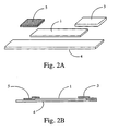
- FIGs. 2A and 2B Another test strip is shown in Figs. 2A and 2B .
- a reagent pad 5 at one end and absorbent pad 3 at the respective other end.
- the reagent pad 5 is shown partially overlapping the test membrane 1 to thus produce a greater degree of saturation thereacross, as may be desired for a given application.
- test strip embodiments depicted in Figs. 1a-1c and Figs. 2a-2b it will be readily understood and appreciated by those skilled in the art that the same are designed to produce a lateral flow or path of migration that extends from the reagent pad 5 to the absorbent pad 3 at the other end.
- the lateral flow of a reaction mixture across the test membrane 1 provides a basis for conducting chemical analyses over a given surface area (i.e., the test membrane 1).
- the methods of the present invention and the assays do not utilize a capture barrier formed by bound receptors formed along a portion of the test membrane 1, but rather utilize a novel magnetic approach to generate such capture lines.
- the test strip configurations depicted in Figs. 1 and 2 may be readily utilized in the practice of the present invention, and one essential element thereof comprises a chromatographic medium, such as a test strip or chromatographic plate, upon which a test sample may flow laterally thereacross. It will be understood that a path of migration need not necessarily be formed, as per conventional test strips and the like, in order to practice the present invention.
- the test membrane 1 can be selected from any available material having appropriate thickness, pore size, lateral flow rate, and color. It is preferred that the test membrane be made from a material which has a low affinity for the analyte and test reagents. This is to minimize or avoid pretreatment of the test membrane to prevent non-specific binding of analyte and/or reagent. Polyester is an example of a suitable test membrane material.
- the (optional) reagent pad 5 can contain all or a portion of the reagents necessary to complete the assay.
- Reagents can include a capture ligand and reporter ligand which specifically bind different regions of the analyte to be detected in a given sample.
- the capture ligand can be covalently bound or absorbed to the surface of magnetic particles. Capture ligands can also be bound indirectly using binding partners such as anti-IgG antibody, streptavidin/biotin, and others.
- the reporter ligand is covalently bound to a dye, particle, radioisotope, or enzyme which produce fluorescence or luminescence.
- the reagent pad 5 can also contain stabilizers, buffers, surfactants and other agents which improve the performance of the assay.
- the reagent pad 5 can receive the sample and all subsequent liquid reagents used to perform the assay.
- the reagent pad 5 also can be selected from any available material having appropriate thickness, pore size, and flow rate. It is preferred that the reagent pad be made from a material which has a low affinity for the analyte and test reagents. Again, this is to minimize or avoid pretreatment of the reagent pad 5 to prevent non-specific binding of analyte and/or reagent. Polyester and porous polyethylene are examples of suitable reagent pad 5 materials.
- the reagent pad 5 should be of sufficient size and void volume to accept the entire sample volume.
- the reagent pad 5 may not be a physically separate component. Rather, instead the reagents can be stored in a reagent zone 2 formed on the test membrane 1 itself. Alternatively, the reagent pad 5 does not contain reagents and instead is used as a liquid reagent receiving pad. As will be appreciated by those skilled in the art, by forming such reagent zones upon the test membrane as a substitute for reagent pads, the cost and complexity of manufacturing is substantially reduced insofar as the reagent pad component may be eliminated altogether.
- test membrane coupled with the ability to form a capture line magnetically, as discussed more fully below, eliminates the need to design a test strip whereby a fluid sample must necessarily flow sequentially in one direction so that a given fluid sample with reagents thoroughly and precisely comes into contact with a conventional capture zone defined by a multiplicity of bound antibodies.
- the (optional) absorbent pad 3 should have absorbent capacity sufficient to contain all liquid volumes used during the test procedure.
- Cotton fiber and absorbent paper are examples of suitable absorbent pad 3 materials.
- the absorbent pad is optional insofar as the chromatographic medium utilized in the practice of the present invention may merely consist of a test membrane or chromatographic plate and does not necessarily require the use of an absorbent pad to produce or generate a direction of flow or path of migration for a given test sample, as is typically required in prior art assay strips.
- the magnetic chromatography test strip backing 4 can be made of plastic, glass or other suitably rigid material.
- the backing length can exceed the length required to support the test membrane and pads, as may be desired to serve several functions.
- such extended backing length can provide a handle or it can display information such as bar codes, fluorescent marks, and colored marks which can aid in the calibration of the individual test strip and multimode photometer, as discussed more fully below.
- Fig. 5a there is shown a top view of a multiplicity of test strips arrayed in parallel rows on a common backing 4.
- the backing 4 has a top side and bottom side and can be in sheet or roll form and is preferably manufactured from an opaque plastic sheet material of appropriate color, thickness, and rigidity.
- Each respective test membrane 1 is sufficiently spaced to avoid fluid contact between adjoining test membranes 1.
- An absorbent pad 3 is preferably positioned to be in fluid contact at one end of the test membrane 1.
- Fig. 5b shows a top view of test strips manufactured using a single common absorbent pad 3 having fluid contact with all test membranes in a given row. Placement of test membranes 1 and absorbent pads 3 are such that multiple parallel rows of test strips are advantageously manufactured on a sheet or continuous web of backing 4. Each row of test strips is positioned with adequate spacing such that individual test strips for different rows are not in fluid contact with each other.
- the novel methods of the present invention deploy a magnetic field at the reaction mixture receiving site upon the test membrane portion of the test strips.
- Such magnetic field which may be generated by any type of magnetic source, such as a permanent magnet or an electromagnet, is selectively positioned such that when applied to a portion of the test membrane, magnetic particles present within a given sample will become substantially bound at the specific site where the magnetic field is applied.
- the applied magnetic field attracts the magnetic particles forming a magnetic barrier that selectively retains magnetic particles, with the analyte of interest having complexed thereon with appropriate labels bound thereto, while allowing the remainder of the reaction mixture to flow laterally across such barrier or zone.
- a magnetic barrier is formed using a bar magnet(s) 20 laminated or placed in close proximity to the bottom side of backing 4.
- the bar magnet(s) or magnetized rail(s) 20 is positioned perpendicular to the test membrane(s) 1 in each row and between said test membrane(s) 1 fluid receiving and absorbent ends.
- a reagent zone 2 is positioned at the fluid receiving end of each test membrane.
- a capture line is magnetically assembled thereon insofar as magnetic particles are substantially immobilized by the magnetic field at a specific site or sites situated across the test membrane.
- the remaining reaction mixture components which are not magnetically bound thus continue to flow laterally within the test membrane, typically in a path of migration toward an absorbent pad.
- such method allows more than one analyte, control, calibrant, or combination of these to be quantitatively assayed on a single test strip. Accordingly, it is an object of this invention to provide a useful method for the performance of assays, e.g. biological assays.
- test strips depicted in Figs. 1a-1c and Figs. 2a-2b depict only one section of test membrane disposed between a reagent pad and an absorbent pad, it will be recognized by those skilled in the art that when more than one analyte, control, calibrator, or combination thereof are to be assayed within a test solution using a single test strip, a cascade of reagent zones or pads can be placed down stream from the first applied magnetic field.
- flow test strip assemblies which can be used with magnetic chromatography are given:
- the multiple assay examples given causes test solution to encounter two groups of magnetic particles.
- the flow of test solution is unilateral moving from reagent zone or pad 1 at one end of the test strip to absorbent pad at the opposite end of the test strip.
- Magnetic barriers are positioned at each test membrane. The first magnetic barrier is positioned across the test membrane prior to reagent zone or pad 2 while the second magnetic barrier is positioned across the test membrane prior to the absorbent pad. Reagents from reagent zone or pad 2 can be used to analyze additional analytes in the test solution or can be used to perform calibration or quality control.
- the opposing multiple assay example given will allow assay of identical analytes from separate test solutions. This is advantageous when a calibrator must be assayed simultaneously with a test sample.
- the flow of test solution is from each reagent pad or zone toward a single common absorbent pad. Magnetic barriers are positioned across each test membrane. It is also anticipated that magnetic chromatography can be used with other multiple assay test strip configurations including rosettes, parallel arrays, and others.
- the width of such capture line may be selectively controlled depending upon the number of magnets and/or degree of magnetic force applied to the test membrane.
- the increased number of magnets applied thereto correspondingly produces an increase in the width of the capture line.
- the corresponding capture line produced thereby will have a greater surface area which, as a consequence, can be utilized to determine concentration per unit area.
- manipulating the magnetic field to produce a wider or narrower capture line or area may prove extremely beneficial.
- a means may thus be provided to facilitate the inspection of individual particles utilizing a microscope.
- selective manipulation of the capture zone may be used to isolate target cells from a population of cells, and thereafter perform microscopic inspection thereof as may be necessary for a given application.
- bar magnets and/or magnetized rails may be utilized whose width is between 0.0762 mm to 7.62 cm (0.003 to 3.0 inches), and whose length is between 0.254 mm to 2.54 cm (0.10 inches to 100 inches).
- magnets, and in particular magnetized rails may be sized and configured to generate any degree of magnetic field necessary to form a desired capture line and may be readily determined for a given application by one having ordinary skill in the art.
- test strip for performing the assays of the present invention. Unlike the aforementioned test strips, however, such test strip is specifically designed and configured to form a capture line at the point of contact at which a reaction mixture containing magnetic particles is introduced to the strip.
- the capture point at the initial point of contact at which the reaction mixture is contacted with the test strip, there is advantageously conserved the amount of analyte sought to be detected through the assay which, unlike prior art devices and methods, can diffuse away from the capture zone of bound receptors or otherwise be restrained from reaching such capture zone due to nonspecific binding.
- a significant portion of the analyte sought to be detected through use of conventional assays can go undetected by virtue of the sequential lateral flow that must occur from when the reaction mixture is introduced to an assay to the point where such reaction mixture comes into contact with the bound receptors forming the sought-after capture line.
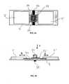
- an elongate backing 4 having first and second opposed ends and an intermediate portion.
- such backing may be made of glass, plastic, or other suitably rigid material.
- first and second absorbent pads 3', 3" are Formed upon the opposed ends of the backing.
- first and second absorbent pads 3', 3" are formed upon the opposed ends of the backing.
- first and second absorbent pads 3', 3" are formed upon the opposed ends of the backing.
- first and second absorbent pads 3', 3" which, as discussed more fully below, caused the reaction mixture to ultimately flow bilaterally from the point of contact at which the reaction mixture is introduced to the test strip.
- elongate magnet 30 Affixed underneath the backing 4 is an elongate magnet 30, which is utilized to create the capture line for use in further analysis.
- the elongate magnet 30 may be proximately positioned underneath the backing 4 in order to yield a plurality of advantages, such as facilitating microscopic applications.
- first vertical flow mesh 32 and second lateral flow mesh 34 Formed upon the intermediate portion of the backing 4 between the first and second absorbent pads 3', 3", and centered over the magnet 30 are preferably provided first vertical flow mesh 32 and second lateral flow mesh 34. As illustrated, the vertical flow mesh 32 is formed on top of lateral flow mesh 34, the latter being in contact with the first and second absorbent pads 3', 3" on opposed sides thereof. Preferably, a portion the lateral flow mesh 34 are partially positioned underneath the first and second absorbent pads 3', 3" as shown. In order to introduce the reaction mixture, there is further preferably provided a sample well 36 which is specifically designed and configured to introduce the reaction mixture directly upon the first vertical mesh 32 so that the same thereafter sequentially flows to the lateral flow mesh 34 and ultimately to the absorbent pads 3', 3" via bilateral flow.
- the vertical flow mesh 32 is formed of polyester, nylon, glass fiber or any other like material and is oriented to facilitate downward flow therethrough in order to filter large debris which may be present in the test solution.
- the lateral flow mesh 34 is similarly formed from polyester, nylon, glass fiber or any other like material to allow bilateral flow to the respective absorbent pads 3', 3".
- the lateral flow mesh 34 may also be formed from materials having magnetic properties, such as metal screens, metalized polyester and the like.
- the sample well 36 is preferably formed from a non-magnetic material such as plastic, and in particular polyvinyl chloride, so as to not react with the magnetic particles present within the reaction mixture.
- the backing 4, and more particularly the intermediate portion thereof may be formed to have a textureized surface that is configured and oriented to direct the flow of sample flowing thereacross.
- any textured surface capable of causing lateral flow of the test solution across the intermediate portion of backing 4 may be utilized in the practice of the present invention, and in particularly as a substitute for the lateral flow mesh 34.
- Fig. 6b there is shown the sequence by which an assay may be performed using the test strip depicted in Fig. 6a.
- the reaction mixture is deposited within the sample well 36. Due to both capillary action and downward gravitational forces, indicated by the letter A, the reaction mixture is sequentially caused to pass through vertical flow mesh 32, lateral flow mesh 34 and ultimately to absorbent pads 3', 3" via lateral flow depicted by the letter B.
- the magnetic particles having the analyte of interest complexed therewith will be caused to become substantially bound within the magnetic zone defined by magnet 30 disposed underneath the backing 4.
- the magnetic particles become captured at the starting point of the assay, as opposed to at some point removed from where the reaction mixture is initially introduced, as occurs through most conventional strip assays.
- the use of textured surfaces formed directly on back 4, or attached thereon may be contemplated. More specifically, any textured surfaces capable of causing lateral flow of the test solution can be utilized as a substitute for the lateral flow mesh 34.
- the analyte sought to be detected is conserved and is not allowed to diffuse or otherwise become bound outside the capture line. As such, this provides enhanced sensitivity that has not heretofor been before available.
- the test strips depicted in Figs. 6a and 6b are exceptionally advantageous for use in isolating particular types of cells, such as cancer cells, and other large molecules and biological structures.
- the size of such structures coupled with their limited quantities in a given sample (e.g. one cancer cell in fifty billion cells, as can be found in a 10ml blood sample), such structures have been difficult to isolate and detect in the past.
- due to their size such structures are physically prevented from reaching the capture or target sites provided to detect their presence.
- the nylon mesh as utilized for the lateral flow mesh 34, is exceptionally advantageous insofar as the same has been shown to substantially increase lateral flow velocity of the reaction mixture away from the capture zone (i.e., the magnetic field generated by magnet 30), which thus increases non-target cell wash out.
- target cells may be retained in greater concentrations and hence may be more easily detected than prior art techniques.
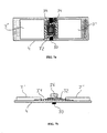
- FIG. 7a and 7b there is provided an alternative bilateral flow test strip depicted in Figs. 7a and 7b.
- Figs. 7a and 7b there is shown the same components of the test strip depicted in Figs. 6a and 6b.
- a backing 4 with first and second absorbent pads 3', 3" formed upon the opposed ends thereof.
- magnet 30, Disposed underneath the backing 4 is magnet 30, provided to generate the magnetic field necessary to produce the desire capture line.
- a sample well 36 for introducing the reaction mixture to the test strip, followed by vertical flow mesh 32 and lateral flow mesh 34.
- such lateral flow mesh 34 is designed to have a generally diagonal orientation relative the vertical flow mesh 32.
- the reaction mixture flowing therethrough experiences increased velocity in flowing to the opposed absorbent pads 3', 3".
- the reaction mixture avoids having to flow in a perpendicular direction per the embodiment depicted in Figs. 6a and 6b, and, as such, does not experience the degree of impedance as would a reaction mixture encounter via the embodiment depicted in Figs. 6a and 6b.
- the intermediate may be to have a texturized surface that is operative to define a specified pathway and flow velocity of the sample flowing thereacross.
- a novel analyzer having a multimode photometer module included therein which can measure front surface fluorescence (fluorimetry mode), luminescence (luminometry mode), and reflectance (densitometry mode) at a single focal point on a test strip is also provided.
- the use of multiple optical methods at a single focal point provides information regarding the quality and structure of an individual capture line as well as the amount of analyte, control, or calibrator present at the capture line. Thus accuracy and precision problems associated with test strip can be minimized by interrogating important test strip locations using two or more optical methods.
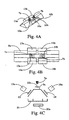
- the multimode photometer consists of an optical canopy 9a and a base 9b which cooperate to form an optical tunnel 9.
- the optical tunnel 9 aligns light sources and photodetectors, with magnetic sources and test membranes, chromatographic plates, etc. to form optical paths.
- base 9b includes a channel formed therein for receiving a test strip of the aforementioned variety.
- the base 9b further preferably includes a magnetic source fixed therein or fixed relative the channel to thus create the desired capture line at a specified location within the optical tunnel 9.
- a magnetic source such as a magnet, may be placed beneath the base of the optical tunnel 9b such that the test strip rests in the channel situated thereabove.
- the optical canopy 9a is formed to have a ceiling through which a light source may be transmitted, and angled sidewalls through which the resultant reflected light may be emitted.
- the multimode photometer, and more particularly the optical tunnel defined thereby may be extruded, machined, or molded from any of a variety of suitable opaque materials, including but not limited to PVC, ABS, or anodized aluminum. As such, the optical tunnel 9 may be fabricated inexpensively from inexpensive materials.
- an excitation path 6 is formed from the light source 7 to a focal point 8 at the base 9b of the optical tunnel 9.
- the magnetic source incorporated into the base 9b for forming the capture line on a given test membrane or chromatographic plate will be precisely aligned with the excitation path 6 such that the path 6 is directly aimed at the capture line produced by such magnetic source.
- LEDs light emitting diodes
- laser diodes laser diodes
- mercury vapor lamps mercury vapor lamps
- xenon lamps are among many suitable light sources which can be used.
- an optical filter 10 can be used to select an excitation wavelength 6.
- This excitation filter 10 can be placed on either side of the canopy wall 9a provided, however, the same is in the excitation path 6 between the light source and test strip 11.
- a test strip 11 is inserted into the optical tunnel 9, such strip is held in position at the base and intersects the excitation path 6 at the focal point 8.
- Emission paths 12 are formed from the focal point to one or more photodetectors 13. Apertures are positioned using a radial geometry in the canopy wall 9a at angles which optically align each photodetector 13 with the focal point 8. Light pipes, optical fibers, and other wave guides can be used to transmit emission light to the photodetectors 13. Excitation light 6 excites fluorophores present on the test strip 11 at the focal point 8, which then emit light 12 of a longer wavelength. If luminescence is used excitation light 6 is not required and can be omitted during luminescence measurement. Emission filters 14 are used to specifically select the emission wavelength 12 of the light emitted from the flourescent or luminescence and to remove traces of excitation light 6. As will be appreciated by those skilled in the art, such emission filter 14 can be placed on either side of the canopy wall 9a providing it is in the emission path 12 between the photodetector 13 and test strip 11.
- Reflectance paths 15 are also formed from the focal point 8 to one or more photodetectors 16. Such reflectance path 15 carries both excitation 6 and emission light 12. If necessary, excitation filters 10 can be used to specifically select the excitation wavelength 6 of the light reflected from the test strip and to revoke traces of emission light 12. This excitation filter 10 can be placed on either side of the canopy wall 9a providing it is in the reflectance path 15 between the photodetector 16 and test strip 11.
- the filters 10 and 14 can be of the type known in the art as interference filters, due to the way in which the same block out-of-band transmissions.
- interference filters exhibit an extremely low transmission outside of their characteristic bandpass and, as such, are very efficient in selecting the desired excitation and emission wavelengths.
- an optical tunnel can have multiple focal points at which photometric measurements can be made simultaneously, which advantageously allows multiple points on a test strip to be used for sample analysis and/or calibration.
- optical components such as LEDs, photodiodes, and interference filters, may be clustered at each focal point along the optical tunnel.
- FIGs. 4a and 4b there is shown different views of an optical tunnel equipped with two optical clusters as may be utilized for multispectral analysis.
- a light source 7 LEDs 7a and 7b are shown
- an excitation filter 10 filters 10a and 10b are shown
- a bar magnet 20a is positioned at the base of the optical tunnel beneath each focal point 8 such that appropriate spectrophotometric analysis may be made at each location.
- test solution can mean test sample, test calibrator, or test control material.
- a test strip is manufactured according to the description given in Fig. 1.
- the backing 4 is extended in length beyond the absorbent pad 3 end to allow application of bar codes, fluorescent markings, and other indicators to the backing 4.
- Reagent zone 2 contains streptavidin conjugated magnetic particles, buffers, stabilizers, surfactants, and other reagents in dry form.
- the test strip 11 is inserted absorbent pad 3 end first into the optical tunnel 9.
- Indicators on the test strip are interpreted as calibration information by the analyzer.
- the analyzer verifies that the same bar code was read at both focal points 8a and 8b and stores reflectance and fluorescence values for photodetectors 13 and 16.
- the calibration information and measured values are used by the analyzer to verify the quality and structure of an individual capture line as well as the amount of analyte, control, or calibrator present at the capture line, and to verify the performance of each optical module.
- test reagents include biotin conjugated anti-beta HCG, and fluorescent microsphere conjugated anti-alpha HCG which cooperatively bind HCG molecules present in the sample.
- a measured volume of this reaction mixture is applied to the test strip reagent zone 2 it forms a new reaction mixture which contains magnetic particles in suspension as buffers, stabilizers, surfactants, and other reagents previously dried on the reagent zone 2.
- the magnetic particles bind the biotin conjugate in all of its complexed forms including those which have formed a cooperative complex (sandwich assay) with HCG and the anti-alpha HCG conjugate.
- fluorescent microspheres are indirectly bound to magnetic particles in proportion to the amount of analyte present in the reaction mixture.
- the magnetic particles suspended in the reaction mixture flow laterally within the plane of the test strip 11 they encounter a magnetic field applied using a bar magnet 20 attached to the base 9b of the optical tunnel 9.
- the applied magnetic field attracts the magnetic particles forming a magnetic barrier that selectively retains the magnetic particles at the focal point 8 while allowing reaction mixture to continue to flow laterally across this barrier toward the absorbent pad 3.
- a measured volume of wash solution can also be added subsequent to the addition of reaction mixture. This will reduce the amount of fluorescent microspheres retained by the test membrane 1 and magnetic particles due to non-specific binding.
- the analyzer monitors and compares photodetectors 16a and 16b measuring reflectance at the focal point 8a and 8b.
- the reflected light intensity at the focal point 8a decreases as the magnetic particles are retained by the magnet 20.
- the reflected light intensity at focal point 8b is a background (blank) measurement used to correct for differences between individual test strips and sample matrix effects. This allows the analyzer to determine whether the magnetic particles have been properly captured at focal point 8a, and to reject samples which are hemolyzed or contain elevated amounts of chromophores such as bilirubin. If the reflected light intensity is not within specification at focal points 8a and 8b during a predefined elapsed time the test is determined invalid and no result is reported.
- the analyzer also monitors and compares photodetectors 13a and 13b measuring fluorescence.
- the emitted light intensity at focal point 8b is a background (blank) measurement used to correct for non-specific binding, differences between individual test strips, and sample matrix effects.
- the analyzer compares the blank emission measurement at 8b and test emission measurement at 8a and calculates HCG concentration.
- Example 2 mirrors Example 1 but for the following differences:
- Reagent zone 2 contains all test reagents prepackaged in unit dose dried form including: streptavidin conjugated magnetic particles, biotin conjugated anti-beta HCG, and fluorescent microsphere conjugated anti-alpha HCG which cooperatively bind HCG molecules present in the sample.
- Reagent zone 2 also contains buffers, stabilizers, surfactants, and other reagents in dry form.
- the operator adds a measured volume of test solution directly to reagent zone 2.
- Example 3 mirrors Example 2 but for the following differences:
- Anti-alpha HCG is conjugated using alkaline phosphatase, instead of fluorescent microspheres.
- a measured volume of fluorescent substrate is added to the reagent zone 2 subsequent to the addition of a measured volume of wash solution.
- Example 4 mirrors all of the above examples but for the following differences:
- Example 4 substitutes a reagent pad 5 for reagent zone 2 in each of the preceding examples.
- a test strip is manufactured according to the prescription given in Fig. 1.
- the backing 4 is extended in length beyond the absorbent pad 3 end to allow application of bar codes, fluorescent markings, and other indicators to the backing 4.
- Reagent zone 2 contains streptavidin conjugated magnetic particles, buffers, stabilizers, surfactants, and other reagents in dry form.
- test solution containing cells, cell lysate, total RNA
- test reagents include biotinylated oligo (dT) probe and a 5' fluorescent dye labeled DNA hybridization probe specific for chlamydia.
- a measured volume of this reaction mixture is applied to the test strip reagent zone 2.
- the reaction mixture comes in contact with the reagent zone 2 it forms a new reaction mixture which contains magnetic particles in suspension as well as buffers, stabilizers, surfactants, and other reagents previously dried in the reagent zone 2.
- the biotinylated oligo (dT) probe hybridizes specifically to the 3' poly(A) region of all mRNA present in the test solution. Consequentially, all mRNA is bound to the magnetic particles via a biotin/streptavidin bond. Labeled hybridization probe, in contrast, binds only target mRNA.
- the magnetic particles bind the biotinylated oligo (dT) probe in all of its complexed forms including those which have formed a cooperative complex (hybrid) with chlamydia mRNA and the fluorescent dye labeled DNA hybridization probe specific for chlamydia.
- fluorescent dye is indirectly bound to magnetic particles in proportion to the amount of chlamydia mRNA present in the reaction mixture.
- the magnetic particles suspended in the reaction mixture flow laterally within the plane of the test strip 11 they encounter a magnetic field applied using a bar magnet 20 attached to the base 9b of the optical tunnel 9.
- the applied magnetic field attracts the magnetic particles forming a magnetic barrier that selectively retains the magnetic particles at the focal point 8 while allowing reaction mixture to continue to flow laterally across this barrier toward the absorbent pad 3.
- a measured volume of wash solution can also be added subsequent to the addition of reaction mixture. This will reduce the amount of labeled DNA probe retained by the test membrane 1 and magnetic particles due to non-specific binding.
- the analyzer monitors and compares photodetectors 16a and 16b measuring reflectance at the focal point 8a and 8b.
- the reflected light intensity at the focal point 8a decreases as the magnetic particles are retained by the magnet 20.
- the reflected light intensity at focal point 8b is a background (blank) measurement used to correct for differences between individual test strips and sample matrix effects. This allows the analyzer to determine whether the magnetic particles have been properly captured at focal point 8a, and to reject samples which are hemolyzed or contain elevated amounts of chromophores such as bilirubin. If the reflected light intensity is not within specification at focal points 8a and 8b during a predefined elapsed time the test is determined invalid and no result is reported.
- the analyzer also monitors and compares photodetectors 13a and 13b measuring fluorescence.
- the emitted light intensity at focal point 8b is a background (blank) measurement used to correct for non-specific binding, differences between individual test strips, and sample matrix effects.
- the analyzer compares the blank emission measurement at 8b and test emission measurement at 8a and calculates chlamydia concentration or determines simply if chlamydia is present in the test solution.
- x-ray film is used to detect the presence of target DNA in a population of transfected cells.
- PCR amplification of CDNA present in each test solution is accomplished using P32 labeled nucleotides.
- Amplified DNA is hybridized using 5' biotin DNA hybridization probe forming a reaction mixture which is applied to the test strip reagent zone 2 containing streptavidin conjugated magnetic particles.
- a wash solution is applied to reagent zone 2 subsequent to application of the reaction mixture.
- a sheet of x-ray film is placed on top of said test strip array and exposed for a suitable length of time.
- a visible band is seen on the developed x-ray film whose position corresponds with a sample which has tested positive for the target DNA.
- Example 7 mirrors Example 6 but for the following differences:
- Said PCR amplification is accomplished using 5' fluorescent dye labeled primer.
- Said test strip array is positioned within a fluorescent scanner.
- Said fluorescent scanner detects a fluorescent band whose position corresponds with a sample testing positive for the target DNA.
- Example 8 mirrors Example 1 but for the following differences:
- Said backing 4 is a microscope slide.
- Said magnet 20 is positioned above said test membrane 1, so that magnet 20 is not in contact with test membrane 1.
- a fluorescent microscope is used to count individual fluorescent microspheres bound to magnetic particles.
- a test strip is manufactured according to the description given in Fig. 1.
- the backing 4 is extended in length beyond the absorbent pad 3 end to allow application of bar codes, fluorescent markings, and other indicators to the backing 4.
- Reagent zone 2 contains streptavidin conjugated 0.86 micron magnetic particles, anti-mouse IgG conjugated 150 nm magnetic particles, buffers, stabilizers, surfactants, and other reagents in dry form.
- the test strip 11 is inserted absorbent pad 3 end first into the optical tunnel 9.
- Indicators on the test strip are interpreted as calibration information by the analyzer.
- the analyzer verifies that the same bar code was read at both focal points 8a and 8b and stores reflectance and fluorescence values for photodetectors 13 and 16.
- the calibration information and measured values are used by the analyzer to verify the quality and structure of an individual capture line as well as the amount of analyte, control, or calibrator present at the capture line, and to verify the performance of each optical module.
- test reagents include biotin conjugated goat anti-beta FSH, and fluorescent microsphere conjugated goat anti-alpha FSH which cooperatively bind FSH molecules present in the sample.
- the test reagents also include mouse anti-beta LH, and fluorescent microsphere conjugated goat anti-alpha LH which cooperatively bind FSH molecules present in the sample.
- a measured volume of this reaction mixture is applied to the test strip reagent zone 2.
- the reaction mixture comes in contact with the reagent zone 2 it forms a new reaction mixture which contains 0.86 micron and 150 nm magnetic particles in suspension as well as buffers, stabilizers, surfactants, and other reagents previously dried on the reagent zone 2.
- the 0.86 micron magnetic particles bind the biotin conjugate in all of its complexed forms including those which have formed a cooperative complex (sandwich assay) with FSH and the anti-alpha FSH conjugate.
- fluorescent microspheres are indirectly bound to magnetic particles in proportion to the amount of analyte present in the reaction mixture.
- the 150 nm magnetic particles bind the mouse anti-beta LH conjugate in all of its complexed forms including those which have formed a cooperative complex (sandwich assay) with LH and the goat anti-alpha LH conjugate.
- fluorescent microspheres are indirectly bound to magnetic particles in proportion to the amount of analyte present in the reaction mixture.
- the applied magnetic field is of sufficient strength that it provides a magnetic barrier that selectively retains the 0.86 micron magnetic particles at the focal point 8a while allowing reaction mixture including 150 nm magnetic particles in suspension to continue to flow lateral across this barrier toward the absorbent pad 3.
- the 150 nm magnetic particles suspended in the reaction mixture flow laterally within the plane of the test strip 11 they encounter a second magnetic field applied using a second bar magnet 20b (not shown) attached to the base 9b of the optical tunnel 9.
- the second applied magnetic field is significantly stronger than said first applied magnetic field.
- This second applied magnetic field provides a magnetic barrier that selectively retains the 150 nm magnetic particles at the focal point 8b while allowing reaction mixture to continue to flow laterally across this second magnetic barrier toward the absorbent pad 3.
- a measured volume of wash solution can also be added subsequent to the addition of reaction mixture. This will reduce the amount of fluorescent microspheres retained by the test membrane 1 and magnetic particles due to non-specific binding.
- the analyzer monitors and compares photodetectors 16a and 16b measuring reflectance at the focal point 8a and 8b.
- the reflected light intensity at the focal point 8a decreases as the magnetic particles are retained by the first magnet 20a and second magnet (not shown).
- the reflected light intensity at focal points 8a and 8b are measurements used to determine whether the magnetic particles have been properly captured at focal points 8a and 8b. If the reflected light intensity is not within specification at focal point 8a and 8b during a predefined elapsed time the test is determined invalid and no result is reported.
- the analyzer also monitors and compares photodetectors 13a and 13b measuring fluorescence.
- the emitted light intensity at focal points 8a and 8b are used to calculate FSH and LH concentrations respectively.
- the analyzer compares these emitted light intensities with those of test solutions containing known concentrations of FSH and LH, based upon such parameters, and calculates FSH and LH concentrations.
- additional capture lines may be formed as per conventional test strip assays which incorporate the use of bound receptors formed upon a test membrane.
- a test strip is manufactured according to the description given in Figs. 7a and 7b.
- the backing 4 is formed from a microscope slide.
- the lateral flow mesh 34 (chromatographic medium or stationary phase) consists of a 105 micron pore size mesh constructed from woven nylon fiber.
- the edges of the respective mesh 32, 34 are adhered to the microscope slide backing 4 using any suitable adhesive tape. This creates an adhesive free zone and allows the lateral flow mesh 34 to make direct contact with the microscope slide backing 4.
- the well 36 is mounted concentric with the respective mesh 32, 34 using any suitable adhesive or any other mechanical means which does not interfere with bilateral flow B of the test solutions.
- the absorbent pads 3', 3" are of approximately equal dimensions having a total absorbent capacity greater than the combined volumes of liquid reagents, test solutions, wash solutions and the like. As illustrated in Figs. 7a and 7b, both absorbent pads 3', 3" are in fluid contact with the lateral flow mesh 34.
- test solution e.g., peripheral blood or bone marrow suspected of containing cancer cells
- test reagents may comprise magnetic particles conjugated using antibodies specific for at least one human cancer cell type. These antibodies bind to the targeted cancer cell type(s) to make them magnetic. Subsequently, a measured volume of fluorescent dye labeled antibodies specific for the same cancer cell type(s) are added to the same reaction mixture. These antibodies may bind to the remaining available sites on the cancer cell type(s) to make them fluorescent. Therefore, the reaction mixture contains cancer cell type(s) that have been rendered both magnetic and fluorescent.
- the test strip is strategically placed above the bar magnet 30 such that an opening at the bottom of the well 36 is positioned above the bar magnet 30.
- the opening at the bottom of the well 36 is circumscribed entirely by the bar magnet 30.
- the reaction mixture is deposited into the well 36. Gravity subsequently causes the reaction mixture to descend through the well 36 along direction A until it comes in contact with the vertical mesh 32. Upon contacting the vertical mesh 32, the reaction mixture is forced through the pores within the vertical mesh 32 by a combination of capillary action and gravitational force. The reaction mixture may then contact the lateral flow mesh 34 which conveys the liquid reaction mixture in bilateral directions B', B" by the capillary action until said reaction mixture is absorbed by the absorbent pads 3', 3".
- the magnetic particles and magnetically labeled cells in the reaction mixture flow from the well 36 to the lateral flow mesh 34, they encounter a magnetic field that is applied via the bar magnet 30.
- the applied magnetic field forms a magnetic barrier that selectively retains a majority of the magnetic particles and magnetically labeled cancer cells within a narrow capture zone.
- the non-magnetic remainder of the reaction mixture may continue to flow bilaterally B across this barrier to the absorbent pads 3', 3".
- a volume of wash solution may be deposited in the well 36 while the test strip remains in position over the bar magnet 30.
- the magnetically labeled target cells and magnetic particles will remain held by the magnetic barrier while the non-target cells and unbound fluorescent antibodies are washed from the capture zone.
- Example 11 mirrors Example 10 but for the following differences:
- a test strip is manufactured according to the description given in FIG. 7.
- the backing 4 is formed from a microscope slide that has been fabricated using an optically clear plastic such as polycarbonate or acrylic.
- the chromatographic medium or stationary phase 34 consists of a texture that is formed directly on the top surface of the microscope slide during the fabrication process (e.g.; injection molding, hot stamping, or casting).
- the texture can take any form suitable to achieve lateral flow of test solutions and reagents by capillary force.
Landscapes
- Health & Medical Sciences (AREA)
- Immunology (AREA)
- Life Sciences & Earth Sciences (AREA)
- Engineering & Computer Science (AREA)
- Chemical & Material Sciences (AREA)
- Urology & Nephrology (AREA)
- Hematology (AREA)
- Biomedical Technology (AREA)
- Molecular Biology (AREA)
- Analytical Chemistry (AREA)
- General Health & Medical Sciences (AREA)
- Cell Biology (AREA)
- Chemical Kinetics & Catalysis (AREA)
- Food Science & Technology (AREA)
- Medicinal Chemistry (AREA)
- Physics & Mathematics (AREA)
- Biotechnology (AREA)
- Biochemistry (AREA)
- Microbiology (AREA)
- General Physics & Mathematics (AREA)
- Pathology (AREA)
- Apparatus Associated With Microorganisms And Enzymes (AREA)
- Investigating Or Analysing Biological Materials (AREA)
- Other Investigation Or Analysis Of Materials By Electrical Means (AREA)
- Investigating Or Analyzing Materials By The Use Of Magnetic Means (AREA)
- Investigating Or Analysing Materials By The Use Of Chemical Reactions (AREA)
Description
- Ligand-receptor assays or immunoassays are well-known in the art. Since their introduction in 1971, such assays have been utilized in a variety of applications to detect minute amounts of hormones, drugs, antibodies, and other substances suspected of being present in a given fluid sample. In this regard, researchers equipped with enzymes, antibodies, gene probes, and other reagents have made it possible to create chemical detection schemes for almost any compound of interest in a great diversity of applications. Among these applications are: commercial production of pharmaceuticals and food stuffs; food safety; diagnosis and treatment of disease in medical, veterinary, and agricultural environs; and detection and eradication of toxins in the environment. Common to all such applications is the requirement that chemical detection be performed in a timely, reliable, and cost effective manner.
- Generally, bioassay schemes are developed and commercialized in formats suitable for use in laboratories equipped with general purpose instrumentation. Examples of these formats include immunoassay and DNA hybridization performed in test tubes, cuvettes, microtiter plates, columns, and electrophoretic gels. These formats usually include elaborate operational procedures and require frequent calibration using several calibrants which contain the analyte of interest at different concentrations. As a consequence, the high cost and complexity of operation associated with such formats limits widespread utilization thereof.
- To address such drawbacks, developers and end users of immunoassays are increasingly replacing conventional bioassay formats which use test tubes, cuvettes, microtiter plates, columns, and electrophoretic gels with thin film chromatographic devices known as test strips. As is known in the art, the majority of test strips used for immunochemical detection of compounds are so called lateral flow test strips in which sample and reagents flow within the plane of the test strip. Advantageously, assays configured in a test strip format can produce rapid results, are simpler to operate, and are more cost-effective than conventional formats. Additionally, such test strip assays may be utilized by unskilled laborers and can produce results on-site (i.e., outside a laboratory facility).
- Generally, such assays rely on the binding of analytes by receptors to determine the concentration of such analytes in a given sample and are typically characterized as either competitive or non-competitive. Non-competitive assays generally utilize receptors in substantial excess over the concentration of analytes to be determined in the assay. Typical of such non-competitive immunoassays include sandwich assays, which detect the presence of an analyte by binding two receptors thereto. In such arrangement, the first receptor, which is typically an antibody is bound to a solid phase such that when the analyte is present, such analyte becomes affixed thereto. A second receptor having a label covalently attached thereto, which may comprise a radioactive, fluorescent, enzymatic, dye or other detectable moiety (collectively referred to as tracers), is introduced to the assay which consequently binds to the bound ligand, to the extent the ligand is present, and thereafter produces a signal consistent with the presence of such ligand. If the sample does not contain the molecules of interest, the labeled receptor is carried past the immobilized receptor without reacting which, as a consequence, will not cause a change in the membrane. Such non-competitive immunoassays are primarily useful for the detection of large molecules such as proteins, large hormones or molecules which have multiple binding sites, such as human chorionic gonadotropin (HCG) and typically will not work with small molecules that have only one binding site.
- Competitive assays, in contrast, generally involve competition between a ligand present in a given sample, and a ligand analog having a tracer/label covalently linked thereto to permit detection for a limited number of binding sites provided by the ligand receptor, which typically comprises an antibody bound to a solid phase. Such assays are particularly suited to detect smaller molecules, such as drugs and drug metabolites. In this context, drug analogs are utilized that have been covalently bound to a protein which is then immobilized on a membrane. Antibody specific to the drug is then labeled and immobilized on a porous pad. When a sample is added which is suspected of containing a given analyte, such sample dissolves the labeled antibody and carries it into contact with the immobilized drug-protein region. If there is little or no drug in the sample, a large amount of the labeled antibody is bound to the immobilized drug-protein region which, consequently, produces a detectable signal. If the sample contains a high amount of drug, little or no labeled antibody is bound to the immobilized drug-protein region and thus in turn gives little or no signal.
- Today, rapid immunoassays generally consists of an adhesive-covered plastic backing onto which several porous pads and a piece of protein-binding membrane are attached. The membrane typically contains a section that has been impregnated with a binding partner (i.e., a receptor or ligand analog). A second pad is typically provided which contains a labeled target molecule or labeled antibody protein-binding membrane. When a sample suspected of containing a target ligand is contacted with the immunoassay, such sample dissolves the labeled element or tracer and the capillary action of the protein-binding membrane subsequently draws the sample with tracer dissolved therein into contact with the impregnated binding partner. When this reaction occurs, there is a change in the appearance of the binding membrane, with the difference providing a qualitative indication of the presence or absence of the ligand suspected of being present in such sample.
- Typical examples of this form of test strip are those which visually display two parallel lines (known as capture lines) on a test membrane. Capture lines consist of immobilized capture reagents or receptors which are preapplied to the test membrane during its manufacture. In this regard, both virtually all prior art assays, whether competitive or non-competitive, typically deploy a receptor immobilized on a membrane, as assessed above. A schematic representation of the construction of a typical lateral flow test strip is as follows:
- reagent pad // test membrane / capture line / test membrane / capture line / test membrane // absorbent pad.
- symbol / designates a phase boundary within a single chromatographic medium; and
- symbol // designates a union of two separate mediums (chromatographic or other medium).
- One of the two capture lines serves as an indication that the test strip performance has not been compromised. In this regard, such capture line serves an important function by providing quality assurance and integrity of the assay, which is generally considered necessary insofar as individual test strip performance can vary greatly. The second of such capture lines becomes visible only when the sample contains an amount of analyte in excess of a minimum concentration (threshold concentration). Exemplary of such prior art systems and methodologies include the immunoassay systems and test strips disclosed in
United States Patent No. 5,658,723, issued on August 19, 1997, to Oberhardt entitled "Immunoassay System Using Forced Convection Currents" andUnited States Patent No. 5,712,170, issued on January 27, 1998, to Kouvonen, et al. entitled "Test Strip, Its Production and Use". - Unfortunately, despite their cost-effectiveness and simplicity of use, typical test strip format assays are less accurate, less precise, and less sensitive to analyte presence than conventional formats. As a result of such drawbacks, the application of test strip format assays has been limited to semi-quantitative or qualitative assays. Among the more significant factors that contribute to the inaccuracy and imprecision of test strip format assays include the manufacture and use of capture lines. As is widely recognized, the manufacture of consistently uniform capture lines requires elaborate material control and manufacturing processes with rigid specifications that must operate within narrow tolerances. Moreover, to function properly, most test strip formats require that the analytes to be detected must be uniformly captured in a precise geometry at a precise location on the test strip and that factors such as the ambient humidity present at the time of test strip manufacture, type of membrane utilized in such manufacturing process, and a capture reagent-receptor itself contributing greatly to assay inaccuracies and false readings. A detailed discussion regarding the drawbacks associated with the binding of protein capture reagents in immunochromatographic assays can be found in Jones, Kevin D., "Troubleshooting Protein Binding in Nitrocellulose Membranes", Part I, IVD Technology, Volume V, No. II, March-April 1999, pages 32-41 and Part II, IVD Technology, Volume V, No. III, May-June 1999, pages 26-35.
- Of further significant disadvantage is the fact that virtually all test strip format assays are formed to have a sequential, generally-linear configuration so as to facilitate the necessary lateral flow thereacross. Due to the fact that such fluid sample must necessarily migrate from its starting point across the reagent pad, the test membrane, and ultimately across the capture line(s) for detecting the presence of the suspect analyte, a substantial portion of the target analyte is often caused to become dispersed or otherwise inhibited from reaching the bound receptors forming the capture line. As such, a substantial portion of the target analyte sought to be detected can and frequently is missed altogether which can adversely effect the quantitative and qualitative results generated by such assays.
- Such potential to inadvertently fail to detect the presence of a target analyte, whether it be through losing the target analyte sought to be detected or simply overlooking its presence is particularly problematic when attempting to detect the presence of cancer cells in a given fluid sample. For example, in a single 10ml tube of blood, there are approximately fifty billion cells, and the presence of so much as one cancer cell among this cell population can be indicative of the presence of micrometastasis. Utilizing conventional screening techniques, such blood samples are typically processed to isolate the leukocytes present in such sample, which advantageously reduces such fluid sample for example, from 10ml to between 1.0 to 0.5ml, which consequently reduces the cell population from approximately fifty billion to approximately one hundred twenty million. Such procedure, however, typically results in the loss of cancer cells and as such may inadvertantly remove the cancer cells sought to be detected.
- In order to screen for cancer cells, such resultant sample is then portioned and applied to many microscope slides at a ratio of approximately one million cells to each slide, via well-known procedures such as cytospin. As is known, each slide prepared represents another inadvertent loss of cancer cells. Each respective one of the slides must then be meticulously scanned using a microscope. In this respect, each slide is typically divided into four hundred magnified fields comprised of one square millimeter areas that are each reviewed. Typically, such scanning process takes on average a half hour per slide. As a result, to thoroughly examine the condensed population of one hundred twenty million leukocytes present in one 10ml blood sample requires the examination of one hundred twenty slides, producing forty eight thousand images that must be examined over a sixty hour period. Accordingly, even to the extent prior art assay techniques are effective at labeling a target cell sought to be detected, the process by which such labeled cell is ultimately isolated and detected is inherently unreliable, tedious and time consuming.
- It is therefore desirable to devise an alternative lateral flow device which can capture analyte at a precise location, and preferably at the starting point or point of contact at which the fluid sample is deposited. It would likewise be desirable to devise an alternative assay that can capture an analyte at such starting point or point of contact in a precise geometry without the use of preapplied capture lines. There is also a need for an assay that has greater sensitivity in reproduceability than prior art assays and methods and is likewise inexpensive, less labor intensive, relatively easy to manufacture, and capable of being utilized for a wide variety of applications. There is further a need for an assay that may capture prepared cell specimens directly onto microscopic slides and significantly reduce the time and number of required images to be produced therefrom, particularly with respect to the isolation and detection of cancer cells.
- Patent
JP 05 052849 (Teruma corp - The present invention specifically addresses and alleviates to the above-identified deficiencies in the art. In this regard, the present invention pertains to several novel bioassay methodologies. Together with chromatographic devices, and an optional multimode photometer/analyzer bioassays can be performed with accuracy and precision like that of conventional laboratory formats while retaining the operational simplicity, rapid analysis, and cost-effectiveness like that of test strip formats. The novel bioassay methodologies of the present invention and chromatographic devices further minimize problems associated with the manufacture of test strips which incorporate preapplied capture lines and further, can enable an analyte to be detected in a fluid sample in a manner that efficiently conserves and isolates the analyte present in such sample. Moreover, unique chemical analysis methods of the present invention together with multimode photometers and novel test strip devices represent a versatile, cost effective, simple, and accurate system which can quantify the amount of a chemical substance present in a sample that has not heretofore been available via prior art bioassay test strips.
- According to the present invention, there is provided a novel magnetic chromatography method for performing a bioassay comprising the steps:
- a) providing a chromatographic medium;
- b) applying a magnetic field at a site upon said chromatographic medium;
- c) providing a reaction mixture suspected of containing an analyte, a reporter ligand that binds to said analyte and a quantity of magnetic particles with capture ligands for binding said analyte immobilized thereon suspended therein;
- d) contacting said reaction mixture with said chromatographic medium at said magnetic field site such that said reaction mixture flows laterally across said chromatographic medium and a majority of said magnetic particles suspended within said reaction mixture is caused to become captured upon said medium at said site where said magnetic field is applied; and
- e) analyzing said majority of magnetic particles captured upon said chromatographic medium.
- As such, there is thus eliminated the conventional capture lines formed by bound receptors that are utilized in prior art immunoassays as well as analyte loss that can occur during the assay. In this regard, a capture line is in effect assembled during the assay, and preferably at the outset. Advantageously, the magnetic chromatography assay methods of the present invention allow test strips and the like to be manufactured without preapplied capture lines. However, the methods of the present invention also anticipate a magnetic chromatography test strip having both preapplied capture lines and capture lines formed during the bioassay using magnetic chromatography as may be desired for a specific application.
- The novel methods of the present invention may further deploy one or more applied magnetic field source(s) applied to the chromatography test strip assembly to detect multiple spectrophotometric analysis. For example, a common bar magnet or magnetic strip can be attached to the test strip backing with adhesive at one or more locations. Alternately, the magnetic source can be external to the test strip assembly whereby the magnetic source is selectively positioned in close proximity with the test strip while magnetic particles flow laterally therewithin. In preferred embodiments of the present invention, the source of the applied magnetic field may comprise either permanent magnets or electromagnets.
- A novel magnetic chromatography test strip for performing a bioassay that conserves the amount of analyte sought to be detected in a reaction mixture by forming a capture line or zone at the point at which the reaction mixture is contacted with the test strip is also disclosed. The test strip comprises an elongate backing having first and second ends and an intermediate portion disposed therebetween. Upon the intermediate portion are a first vertical mesh for facilitating vertical flow and second lateral mesh for facilitation lateral flow, the latter being disposed underneath the first mesh. On opposed sides of the lateral flow mesh are absorbent pads that, in use, cause the reaction mixture ultimately passing through the first and second meshes to flow bilaterally. Such strip further preferably includes at least one magnet that is positioned underneath the vertical flow mesh and second lateral flow mesh.
- In use, a reaction mixture is sequentially caused to flow from the vertical flow mesh, to the lateral flow mesh, and ultimately to the first and second absorbent pads disposed on the opposed sides of the lateral flow mesh. Preferably, such reaction mixture is deposited upon the strip by means of a sample well. The applied magnetic field provided by the magnet attracts the magnetic particles having the analyte of interest complexed thereto, which thus causes the same to be selectively retained at the site of deposition while the remainder of the reaction mixture continues to flow thereacross and ultimately to the respective of the absorbent pads. Such test strips are particularly well suited for the detection and isolation of cells, such as cancer cells, bacteria and the like, which are otherwise difficult to identify and isolate through prior art methods.
- There is further provided a novel analyzer comprised of a multimode photometer which can measure front surface fluorescence, luminescence and reflectance at a single focal point on the test strips.
- The multimode photometer consists of a base and optical canopy which collectively define an optical tunnel into which at least one test strip may be disposed. The chamber may include a magnetic source or be designed to be placed in close proximity to a magnetic source such that the test strip having activated magnetic particles flowing laterally therewithin may be caused to become substantially bound at a specific site or sites upon the test strip. When so arranged, a light or radiation source may be focused upon the test strip disposed within the optical tunnel such that the light or radiation may be aligned with the magnetic source and the reflected or emitted light from the test strip analyzed for analyte presence. Light and radiation of differing wave lengths may be utilized to determine the presence of appropriate analytes as per conventional spectrophotometric analysis. Optical filters and photodetectors may further be deployed as may be necessary for a particular spectrophotometric applications.
- It is therefore an object of the present invention to provide a novel magnetic chromatography method utilizing a test strip format that has greater sensitivity and reproduceability than prior art test strip assays.
- Another object of the present invention is to provide a novel magnetic chromatography method that utilizes a test strip format, but dispenses with a need to form a capture line by binding receptors to a test membrane.
- Another object of the present invention is to provide a novel magnetic chromatography method that can be arrayed in a test strip format and utilized to provide quantitative analysis.
- Another object of the present invention is to provide a novel magnetic chromatography method that can form a capture line at the point of contact where a reaction member comes into contact with such test strip.
- Another object of the present invention is to provide a novel magnetic chromatography method that can conserve the amount of analyte present in a reaction mixture by identifying and isolating the same at the initiation of the performance of such assay.
- Another object of the present invention is to provide a novel magnetic chromatography method that may be adapted to provide quantitative and qualitative analysis for multiple analytes.
- Another object of the present invention is to provide a novel magnetic chromatography method that is easy to use, of simple construction, and inexpensive to manufacture.
- Another object of the present invention is to provide a novel magnetic chromatography method that may be utilized to provide spectrophotometric analysis, including but not limited to, surface reflectance, surface fluorescence, and surface luminescence.
- Another object of the present invention is to provide a novel magnetic chromatography method which may be configured to isolate target cells and facilitate the ability to detect the same.
- Another object of the present invention is to provide a novel magnetic chromatography method which may be adapted to capture cells directly onto slides and facilitate microscopic examination thereof.
- Another object of the present invention is to provide a novel magnetic chromatography method which may be configured to perform individual sample analysis, batch sample analysis, and linear-array analysis.
- Another object of the present invention is to provide a novel magnetic chromatography method that can be used for quantitative, semi-quantitative, and qualitative immunoassay of analytes and DNA hybridization assays.
- Furthermore, an optical analyzer consisting of a multimode photometer for performing spectrophotometric analysis, including but not limited to, surface reflectance, surface fluorescence, and surface luminescence is provided.
- Furthermore, an analyzer consisting of a multimode photometer which is of simple construction, easy to utilize, and may be configured to perform individual sample analysis, batch sample analysis, and linear-array analysis is provided.
- Furthermore, an analyzer consisting of a multimode photometer that, when utilized in conjunction with the magnetic chromatography assays of the present invention, may be utilized to quantitate the amount of a given analyte at a fixed location on a test strip assay, irrespective of orientation of such assay and lateral flow of reaction mixture utilized therewith is provided.
- These as well as other features of the present invention will become more apparent upon reference to the drawings wherein:
- Fig. 1a is a perspective view of an assay test strip.
- Fig. 1b is an exploded view of the components comprising the assay test strip depicted in Fig. 1a.
- Fig. 1c is a side view of the assay depicted in Fig. 1a.
- Fig. 2a is an exploded perspective view of another assay test strip.
- Fig. 2b is a side view of the assay test strip depicted in Fig. 2a.
- Fig. 3a is a cross-sectional view of a multimode photometer, as utilizable in the practice of the methods of the present invention.
- Fig. 3b is a cross-sectional view and block diagram of the multimode photometer depicted in Fig. 3.
- Fig. 4a is perspective view of the multimode photometer depicted in Fig. 3.
- Fig. 4b is a top view of the multimode photometer depicted in Fig. 3.
- Fig. 4c is an exploded cross-sectional view of the components comprising the multimode photometer depicted in Fig. 3.
- Fig. 5a is a top view of a multiplicity of test strips arrayed in parallel rows on a common backing for use in detecting the presence and quantity of one or more analytes from a plurality of samples.
- Fig. 5b is a top view of a multiplicity of test strips utilizing a single-common absorbent pad having fluid contact with a multiplicity of test membranes, the latter being arranged in a generally linear fashion.
- Fig. 6a is a top view of an assay test strip constructed in accordance with the present invention.
- Fig. 6b is a side view of the test strip depicted in Fig. 6a.
- Fig. 7a is a top view of an assay test strip constructed in accordance with the present invention.
- Fig. 7b is a side view of the assay test strip depicted in Fig. 7a.
- There is disclosed herein a novel assay system and method that, unlike prior art assay systems, and in particular test strip assays, can quantitatively and qualitatively detect the presence of an analyte, control, calibrator, or combination thereof in a given fluid sample with extraordinary precision and reproduceability. Moreover, methods of the present invention and the novel assays provide all of the advantages associated with conventional test strips assays insofar as the same need not undergo remote analysis at a laboratory facility and further, do not require handling by trained professionals. There is further provided a novel analyzer, which comprises a multimode photometer, is useful in conducting spectrophotometric analysis in conjunction with the methods of the present invention and the assays.
- Referring now to the drawings, initially to Figs. 1a-1c, there is shown a test strip for use in magnetic chromatography. The test strip is comprised of a
test membrane 1 having areagent zone 2 at its one end and anabsorbent pad 3 at its other end. These components are attached to abacking 4 made of plastic, glass or other suitably rigid material. Similar to prior art test strips, the test strip is simple to manufacture by lamination. - Another test strip is shown in Figs. 2A and 2B. There is provided a
reagent pad 5 at one end andabsorbent pad 3 at the respective other end. In this regard, thereagent pad 5 is shown partially overlapping thetest membrane 1 to thus produce a greater degree of saturation thereacross, as may be desired for a given application. - In either of the test strip embodiments depicted in Figs. 1a-1c and Figs. 2a-2b, it will be readily understood and appreciated by those skilled in the art that the same are designed to produce a lateral flow or path of migration that extends from the
reagent pad 5 to theabsorbent pad 3 at the other end. As per conventional test strip assays, the lateral flow of a reaction mixture across thetest membrane 1 provides a basis for conducting chemical analyses over a given surface area (i.e., the test membrane 1). - Unlike prior art test strip assays, however, the methods of the present invention and the assays do not utilize a capture barrier formed by bound receptors formed along a portion of the
test membrane 1, but rather utilize a novel magnetic approach to generate such capture lines. In this regard, due to the novel methods by which capture lines are generated via the present invention, it will be recognized that the test strip configurations depicted in Figs. 1 and 2 may be readily utilized in the practice of the present invention, and one essential element thereof comprises a chromatographic medium, such as a test strip or chromatographic plate, upon which a test sample may flow laterally thereacross. It will be understood that a path of migration need not necessarily be formed, as per conventional test strips and the like, in order to practice the present invention. - The
test membrane 1 can be selected from any available material having appropriate thickness, pore size, lateral flow rate, and color. It is preferred that the test membrane be made from a material which has a low affinity for the analyte and test reagents. This is to minimize or avoid pretreatment of the test membrane to prevent non-specific binding of analyte and/or reagent. Polyester is an example of a suitable test membrane material. - The (optional)
reagent pad 5 can contain all or a portion of the reagents necessary to complete the assay. Reagents can include a capture ligand and reporter ligand which specifically bind different regions of the analyte to be detected in a given sample. The capture ligand can be covalently bound or absorbed to the surface of magnetic particles. Capture ligands can also be bound indirectly using binding partners such as anti-IgG antibody, streptavidin/biotin, and others. The reporter ligand is covalently bound to a dye, particle, radioisotope, or enzyme which produce fluorescence or luminescence. Thereagent pad 5 can also contain stabilizers, buffers, surfactants and other agents which improve the performance of the assay. Thereagent pad 5 can receive the sample and all subsequent liquid reagents used to perform the assay. Thereagent pad 5 also can be selected from any available material having appropriate thickness, pore size, and flow rate. It is preferred that the reagent pad be made from a material which has a low affinity for the analyte and test reagents. Again, this is to minimize or avoid pretreatment of thereagent pad 5 to prevent non-specific binding of analyte and/or reagent. Polyester and porous polyethylene are examples ofsuitable reagent pad 5 materials. Thereagent pad 5 should be of sufficient size and void volume to accept the entire sample volume. - The
reagent pad 5 may not be a physically separate component. Rather, instead the reagents can be stored in areagent zone 2 formed on thetest membrane 1 itself. Alternatively, thereagent pad 5 does not contain reagents and instead is used as a liquid reagent receiving pad. As will be appreciated by those skilled in the art, by forming such reagent zones upon the test membrane as a substitute for reagent pads, the cost and complexity of manufacturing is substantially reduced insofar as the reagent pad component may be eliminated altogether. In this regard, the non-binding properties of the test membrane, coupled with the ability to form a capture line magnetically, as discussed more fully below, eliminates the need to design a test strip whereby a fluid sample must necessarily flow sequentially in one direction so that a given fluid sample with reagents thoroughly and precisely comes into contact with a conventional capture zone defined by a multiplicity of bound antibodies. - The (optional)
absorbent pad 3 should have absorbent capacity sufficient to contain all liquid volumes used during the test procedure. Cotton fiber and absorbent paper are examples of suitableabsorbent pad 3 materials. As discussed above, however, the absorbent pad is optional insofar as the chromatographic medium utilized in the practice of the present invention may merely consist of a test membrane or chromatographic plate and does not necessarily require the use of an absorbent pad to produce or generate a direction of flow or path of migration for a given test sample, as is typically required in prior art assay strips. - The magnetic chromatography test strip backing 4 can be made of plastic, glass or other suitably rigid material. The backing length can exceed the length required to support the test membrane and pads, as may be desired to serve several functions. For example, such extended backing length can provide a handle or it can display information such as bar codes, fluorescent marks, and colored marks which can aid in the calibration of the individual test strip and multimode photometer, as discussed more fully below.
- In order to analyze a multiplicity of samples in a single analysis, there is further disclosed herein certain novel assay strips for performing such function. Referring now to Fig. 5a, there is shown a top view of a multiplicity of test strips arrayed in parallel rows on a
common backing 4. Thebacking 4 has a top side and bottom side and can be in sheet or roll form and is preferably manufactured from an opaque plastic sheet material of appropriate color, thickness, and rigidity. Eachrespective test membrane 1 is sufficiently spaced to avoid fluid contact between adjoiningtest membranes 1. Anabsorbent pad 3 is preferably positioned to be in fluid contact at one end of thetest membrane 1. Fig. 5b shows a top view of test strips manufactured using a single commonabsorbent pad 3 having fluid contact with all test membranes in a given row. Placement oftest membranes 1 andabsorbent pads 3 are such that multiple parallel rows of test strips are advantageously manufactured on a sheet or continuous web ofbacking 4. Each row of test strips is positioned with adequate spacing such that individual test strips for different rows are not in fluid contact with each other. - In order to identify the presence of a particular analyte, control, calibrator, or combination thereof, the novel methods of the present invention deploy a magnetic field at the reaction mixture receiving site upon the test membrane portion of the test strips.
- Such magnetic field, which may be generated by any type of magnetic source, such as a permanent magnet or an electromagnet, is selectively positioned such that when applied to a portion of the test membrane, magnetic particles present within a given sample will become substantially bound at the specific site where the magnetic field is applied. In this regard, the applied magnetic field attracts the magnetic particles forming a magnetic barrier that selectively retains magnetic particles, with the analyte of interest having complexed thereon with appropriate labels bound thereto, while allowing the remainder of the reaction mixture to flow laterally across such barrier or zone.
- With respect to those strips depicted in Figs. 5a and 5b, to generate capture zones or lines, a magnetic barrier is formed using a bar magnet(s) 20 laminated or placed in close proximity to the bottom side of
backing 4. The bar magnet(s) or magnetized rail(s) 20 is positioned perpendicular to the test membrane(s) 1 in each row and between said test membrane(s) 1 fluid receiving and absorbent ends. Areagent zone 2 is positioned at the fluid receiving end of each test membrane. - By selectively applying the magnetic field about or upon the test strip, a capture line is magnetically assembled thereon insofar as magnetic particles are substantially immobilized by the magnetic field at a specific site or sites situated across the test membrane. The remaining reaction mixture components which are not magnetically bound thus continue to flow laterally within the test membrane, typically in a path of migration toward an absorbent pad. Advantageously, such method allows more than one analyte, control, calibrant, or combination of these to be quantitatively assayed on a single test strip. Accordingly, it is an object of this invention to provide a useful method for the performance of assays, e.g. biological assays.
- While the test strips depicted in Figs. 1a-1c and Figs. 2a-2b depict only one section of test membrane disposed between a reagent pad and an absorbent pad, it will be recognized by those skilled in the art that when more than one analyte, control, calibrator, or combination thereof are to be assayed within a test solution using a single test strip, a cascade of reagent zones or pads can be placed down stream from the first applied magnetic field. Several schematic examples of flow test strip assemblies which can be used with magnetic chromatography are given:
-
reagent zone 1 / test membrane // absorbent pad
reagent pad 1 // test membrane // absorbent pad -
reagent zone 1 / test membrane /reagent zone 2 / test membrane // absorbent pad
reagent pad 1 // test membrane //reagent pad 2 // test membrane // absorbent pad -
reagent zone 1 / test membrane // absorbent pad // test membrane /reagent zone 2
reagent pad 1 // test membrane // absorbent pad // test membrane //reagent pad 2
where: - symbol / designates a phase boundary within a single chromatographic medium; and
- symbol // designates a union of two separate mediums (chromatographic and other).
- As a consequence, the multiple assay examples given causes test solution to encounter two groups of magnetic particles. The flow of test solution is unilateral moving from reagent zone or
pad 1 at one end of the test strip to absorbent pad at the opposite end of the test strip. Magnetic barriers are positioned at each test membrane. The first magnetic barrier is positioned across the test membrane prior to reagent zone orpad 2 while the second magnetic barrier is positioned across the test membrane prior to the absorbent pad. Reagents from reagent zone orpad 2 can be used to analyze additional analytes in the test solution or can be used to perform calibration or quality control. - The opposing multiple assay example given will allow assay of identical analytes from separate test solutions. This is advantageous when a calibrator must be assayed simultaneously with a test sample. The flow of test solution is from each reagent pad or zone toward a single common absorbent pad. Magnetic barriers are positioned across each test membrane. It is also anticipated that magnetic chromatography can be used with other multiple assay test strip configurations including rosettes, parallel arrays, and others.
- In order to manipulate the width (i.e., surface area) of the capture line formed by the application of a magnetic field to the test strip, it has been unexpectedly discovered that the width of such capture line may be selectively controlled depending upon the number of magnets and/or degree of magnetic force applied to the test membrane. In this regard, it has been discovered that by stacking multiple magnets upon one another beneath the test membrane where the captures zone is sought to be formed, the increased number of magnets applied thereto correspondingly produces an increase in the width of the capture line. As will be appreciated by those skilled in the art, by utilizing a greater degree of magnetic force, the corresponding capture line produced thereby will have a greater surface area which, as a consequence, can be utilized to determine concentration per unit area. Along these lines, it is contemplated that manipulating the magnetic field to produce a wider or narrower capture line or area may prove extremely beneficial. For example, by manipulating the width or surface area of the capture line, a means may thus be provided to facilitate the inspection of individual particles utilizing a microscope. Likewise, such selective manipulation of the capture zone may be used to isolate target cells from a population of cells, and thereafter perform microscopic inspection thereof as may be necessary for a given application.
- With respect to the dimensions of such magnets that are preferably utilized in the practice of the present invention, it is currently believed that bar magnets and/or magnetized rails may be utilized whose width is between 0.0762 mm to 7.62 cm (0.003 to 3.0 inches), and whose length is between 0.254 mm to 2.54 cm (0.10 inches to 100 inches). In this regard, it will be understood that such magnets, and in particular magnetized rails, may be sized and configured to generate any degree of magnetic field necessary to form a desired capture line and may be readily determined for a given application by one having ordinary skill in the art.
- Referring now to Figs. 6a and 6b, there is shown another test strip for performing the assays of the present invention. Unlike the aforementioned test strips, however, such test strip is specifically designed and configured to form a capture line at the point of contact at which a reaction mixture containing magnetic particles is introduced to the strip.
- As will be recognized by those skilled in the art, by forming the capture point at the initial point of contact at which the reaction mixture is contacted with the test strip, there is advantageously conserved the amount of analyte sought to be detected through the assay which, unlike prior art devices and methods, can diffuse away from the capture zone of bound receptors or otherwise be restrained from reaching such capture zone due to nonspecific binding. As is well-recognized in the art, a significant portion of the analyte sought to be detected through use of conventional assays can go undetected by virtue of the sequential lateral flow that must occur from when the reaction mixture is introduced to an assay to the point where such reaction mixture comes into contact with the bound receptors forming the sought-after capture line.
- Referring initially to 6a, it comprises an
elongate backing 4 having first and second opposed ends and an intermediate portion. As stated above, such backing may be made of glass, plastic, or other suitably rigid material. Formed upon the opposed ends of the backing are first and secondabsorbent pads 3', 3" which, as discussed more fully below, caused the reaction mixture to ultimately flow bilaterally from the point of contact at which the reaction mixture is introduced to the test strip. Affixed underneath thebacking 4 is anelongate magnet 30, which is utilized to create the capture line for use in further analysis. In the alternative, theelongate magnet 30 may be proximately positioned underneath thebacking 4 in order to yield a plurality of advantages, such as facilitating microscopic applications. - Formed upon the intermediate portion of the
backing 4 between the first and secondabsorbent pads 3', 3", and centered over themagnet 30 are preferably provided firstvertical flow mesh 32 and secondlateral flow mesh 34. As illustrated, thevertical flow mesh 32 is formed on top oflateral flow mesh 34, the latter being in contact with the first and secondabsorbent pads 3', 3" on opposed sides thereof. Preferably, a portion thelateral flow mesh 34 are partially positioned underneath the first and secondabsorbent pads 3', 3" as shown. In order to introduce the reaction mixture, there is further preferably provided a sample well 36 which is specifically designed and configured to introduce the reaction mixture directly upon the firstvertical mesh 32 so that the same thereafter sequentially flows to thelateral flow mesh 34 and ultimately to theabsorbent pads 3', 3" via bilateral flow. - The
vertical flow mesh 32 is formed of polyester, nylon, glass fiber or any other like material and is oriented to facilitate downward flow therethrough in order to filter large debris which may be present in the test solution. Thelateral flow mesh 34 is similarly formed from polyester, nylon, glass fiber or any other like material to allow bilateral flow to the respectiveabsorbent pads 3', 3". Thelateral flow mesh 34 may also be formed from materials having magnetic properties, such as metal screens, metalized polyester and the like. The sample well 36 is preferably formed from a non-magnetic material such as plastic, and in particular polyvinyl chloride, so as to not react with the magnetic particles present within the reaction mixture. - As an alternative to providing an arrangement of meshes, such as the combination of
first mesh 32 andsecond mesh 34, discussed above, it is contemplated that thebacking 4, and more particularly the intermediate portion thereof may be formed to have a textureized surface that is configured and oriented to direct the flow of sample flowing thereacross. In this respect, it is contemplated that any textured surface capable of causing lateral flow of the test solution across the intermediate portion ofbacking 4 may be utilized in the practice of the present invention, and in particularly as a substitute for thelateral flow mesh 34. - Referring now to Fig.6b, there is shown the sequence by which an assay may be performed using the test strip depicted in Fig. 6a. Initially, the reaction mixture is deposited within the sample well 36. Due to both capillary action and downward gravitational forces, indicated by the letter A, the reaction mixture is sequentially caused to pass through
vertical flow mesh 32,lateral flow mesh 34 and ultimately toabsorbent pads 3', 3" via lateral flow depicted by the letter B. However, the magnetic particles having the analyte of interest complexed therewith will be caused to become substantially bound within the magnetic zone defined bymagnet 30 disposed underneath thebacking 4. As such, the magnetic particles become captured at the starting point of the assay, as opposed to at some point removed from where the reaction mixture is initially introduced, as occurs through most conventional strip assays. In the alternative, the use of textured surfaces formed directly onback 4, or attached thereon, may be contemplated. More specifically, any textured surfaces capable of causing lateral flow of the test solution can be utilized as a substitute for thelateral flow mesh 34. - Advantageously, the analyte sought to be detected is conserved and is not allowed to diffuse or otherwise become bound outside the capture line. As such, this provides enhanced sensitivity that has not heretofor been before available. Along these lines, it is contemplated that the test strips depicted in Figs. 6a and 6b are exceptionally advantageous for use in isolating particular types of cells, such as cancer cells, and other large molecules and biological structures. In this respect, because of the size of such structures, coupled with their limited quantities in a given sample (e.g. one cancer cell in fifty billion cells, as can be found in a 10ml blood sample), such structures have been difficult to isolate and detect in the past. In this regard, due to their size, such structures are physically prevented from reaching the capture or target sites provided to detect their presence. In such applications, it is found that the nylon mesh, as utilized for the
lateral flow mesh 34, is exceptionally advantageous insofar as the same has been shown to substantially increase lateral flow velocity of the reaction mixture away from the capture zone (i.e., the magnetic field generated by magnet 30), which thus increases non-target cell wash out. As a result, target cells may be retained in greater concentrations and hence may be more easily detected than prior art techniques. - To further enhance the ability of the test strip depicted in Fig. 6a and 6b to increase cell wash out (i.e., facilitate separation and isolation of the target cells from a reaction mixture), there is provided an alternative bilateral flow test strip depicted in Figs. 7a and 7b. Referring initially to 7a, there is shown the same components of the test strip depicted in Figs. 6a and 6b. Specifically , there is provided a
backing 4 with first and secondabsorbent pads 3', 3" formed upon the opposed ends thereof. Disposed underneath thebacking 4 ismagnet 30, provided to generate the magnetic field necessary to produce the desire capture line. There is further provided a sample well 36 for introducing the reaction mixture to the test strip, followed byvertical flow mesh 32 andlateral flow mesh 34. - With respect to the latter, however, such
lateral flow mesh 34 is designed to have a generally diagonal orientation relative thevertical flow mesh 32. As will be appreciated by those skilled in the art, by providing a diagonal orientation of thelateral flow mesh 34 relative thevertical flow mesh 32, the reaction mixture flowing therethrough experiences increased velocity in flowing to the opposedabsorbent pads 3', 3". In this regard, the reaction mixture avoids having to flow in a perpendicular direction per the embodiment depicted in Figs. 6a and 6b, and, as such, does not experience the degree of impedance as would a reaction mixture encounter via the embodiment depicted in Figs. 6a and 6b. As discussed above, as an alternative to utilizing a diagonally orientedlateral flow mesh 34, the intermediate may be to have a texturized surface that is operative to define a specified pathway and flow velocity of the sample flowing thereacross. - A novel analyzer having a multimode photometer module included therein which can measure front surface fluorescence (fluorimetry mode), luminescence (luminometry mode), and reflectance (densitometry mode) at a single focal point on a test strip is also provided. The use of multiple optical methods at a single focal point provides information regarding the quality and structure of an individual capture line as well as the amount of analyte, control, or calibrator present at the capture line. Thus accuracy and precision problems associated with test strip can be minimized by interrogating important test strip locations using two or more optical methods.
- As illustrated in Fig. 3a, the multimode photometer consists of an
optical canopy 9a and abase 9b which cooperate to form an optical tunnel 9. The optical tunnel 9 aligns light sources and photodetectors, with magnetic sources and test membranes, chromatographic plates, etc. to form optical paths. In this regard,base 9b includes a channel formed therein for receiving a test strip of the aforementioned variety. Thebase 9b further preferably includes a magnetic source fixed therein or fixed relative the channel to thus create the desired capture line at a specified location within the optical tunnel 9. For example, a magnetic source, such as a magnet, may be placed beneath the base of theoptical tunnel 9b such that the test strip rests in the channel situated thereabove. - The
optical canopy 9a is formed to have a ceiling through which a light source may be transmitted, and angled sidewalls through which the resultant reflected light may be emitted. As will be recognized by those skilled in the art, the multimode photometer, and more particularly the optical tunnel defined thereby, may be extruded, machined, or molded from any of a variety of suitable opaque materials, including but not limited to PVC, ABS, or anodized aluminum. As such, the optical tunnel 9 may be fabricated inexpensively from inexpensive materials. - Referring now to Fig. 3b, there is schematically illustrated the components utilized for analyzing a test strip with the multimode photometer. Initially, an
excitation path 6 is formed from thelight source 7 to afocal point 8 at thebase 9b of the optical tunnel 9. As will be readily appreciated, the magnetic source incorporated into thebase 9b for forming the capture line on a given test membrane or chromatographic plate will be precisely aligned with theexcitation path 6 such that thepath 6 is directly aimed at the capture line produced by such magnetic source. As will be appreciated, light emitting diodes (LEDs), laser diodes, mercury vapor lamps, and xenon lamps are among many suitable light sources which can be used. If necessary, anoptical filter 10 can be used to select anexcitation wavelength 6. Thisexcitation filter 10 can be placed on either side of thecanopy wall 9a provided, however, the same is in theexcitation path 6 between the light source andtest strip 11. When atest strip 11 is inserted into the optical tunnel 9, such strip is held in position at the base and intersects theexcitation path 6 at thefocal point 8. -
Emission paths 12 are formed from the focal point to one ormore photodetectors 13. Apertures are positioned using a radial geometry in thecanopy wall 9a at angles which optically align eachphotodetector 13 with thefocal point 8. Light pipes, optical fibers, and other wave guides can be used to transmit emission light to thephotodetectors 13.Excitation light 6 excites fluorophores present on thetest strip 11 at thefocal point 8, which then emitlight 12 of a longer wavelength. If luminescence is usedexcitation light 6 is not required and can be omitted during luminescence measurement. Emission filters 14 are used to specifically select theemission wavelength 12 of the light emitted from the flourescent or luminescence and to remove traces ofexcitation light 6. As will be appreciated by those skilled in the art,such emission filter 14 can be placed on either side of thecanopy wall 9a providing it is in theemission path 12 between thephotodetector 13 andtest strip 11. -
Reflectance paths 15 are also formed from thefocal point 8 to one ormore photodetectors 16.Such reflectance path 15 carries bothexcitation 6 andemission light 12. If necessary, excitation filters 10 can be used to specifically select theexcitation wavelength 6 of the light reflected from the test strip and to revoke traces ofemission light 12. Thisexcitation filter 10 can be placed on either side of thecanopy wall 9a providing it is in thereflectance path 15 between thephotodetector 16 andtest strip 11. - The
filters - As will further be appreciated by those skilled in the art, an optical tunnel can have multiple focal points at which photometric measurements can be made simultaneously, which advantageously allows multiple points on a test strip to be used for sample analysis and/or calibration. In such applications, optical components, such as LEDs, photodiodes, and interference filters, may be clustered at each focal point along the optical tunnel.
- As prospectively illustrated in Figs. 4a and 4b, there is shown different views of an optical tunnel equipped with two optical clusters as may be utilized for multispectral analysis. A light source 7 (
LEDs filters photodiodes filters canopy 9a. Abar magnet 20a, as shown in Fig. 4C, is positioned at the base of the optical tunnel beneath eachfocal point 8 such that appropriate spectrophotometric analysis may be made at each location. - Although believed to be apparent from the foregoing discussion, there is provided herebelow a variety of examples by which the novel magnetic assays and methods of the present invention may be utilized in a variety of applications. As will be appreciated by those skilled in the art, for the purpose of discussion in the following examples the term "test solution" can mean test sample, test calibrator, or test control material.
- A test strip is manufactured according to the description given in Fig. 1. The
backing 4 is extended in length beyond theabsorbent pad 3 end to allow application of bar codes, fluorescent markings, and other indicators to thebacking 4.Reagent zone 2 contains streptavidin conjugated magnetic particles, buffers, stabilizers, surfactants, and other reagents in dry form. - The
test strip 11 is insertedabsorbent pad 3 end first into the optical tunnel 9. Indicators on the test strip are interpreted as calibration information by the analyzer. For example, the analyzer verifies that the same bar code was read at both focal points 8a and 8b and stores reflectance and fluorescence values forphotodetectors - In a separate container the operator adds a measured volume of sample to a measured volume of test reagents and mixes them to form a reaction mixture. The test reagents include biotin conjugated anti-beta HCG, and fluorescent microsphere conjugated anti-alpha HCG which cooperatively bind HCG molecules present in the sample.
- A measured volume of this reaction mixture is applied to the test
strip reagent zone 2 it forms a new reaction mixture which contains magnetic particles in suspension as buffers, stabilizers, surfactants, and other reagents previously dried on thereagent zone 2. The magnetic particles bind the biotin conjugate in all of its complexed forms including those which have formed a cooperative complex (sandwich assay) with HCG and the anti-alpha HCG conjugate. Thus, fluorescent microspheres are indirectly bound to magnetic particles in proportion to the amount of analyte present in the reaction mixture. - As the magnetic particles suspended in the reaction mixture flow laterally within the plane of the
test strip 11 they encounter a magnetic field applied using abar magnet 20 attached to thebase 9b of the optical tunnel 9. The applied magnetic field attracts the magnetic particles forming a magnetic barrier that selectively retains the magnetic particles at thefocal point 8 while allowing reaction mixture to continue to flow laterally across this barrier toward theabsorbent pad 3. - A measured volume of wash solution can also be added subsequent to the addition of reaction mixture. This will reduce the amount of fluorescent microspheres retained by the
test membrane 1 and magnetic particles due to non-specific binding. - The analyzer monitors and compares
photodetectors magnet 20. The reflected light intensity at focal point 8b is a background (blank) measurement used to correct for differences between individual test strips and sample matrix effects. This allows the analyzer to determine whether the magnetic particles have been properly captured at focal point 8a, and to reject samples which are hemolyzed or contain elevated amounts of chromophores such as bilirubin. If the reflected light intensity is not within specification at focal points 8a and 8b during a predefined elapsed time the test is determined invalid and no result is reported. - Alternating with
photodetectors photodetectors - Example 2 mirrors Example 1 but for the following differences:
-
Reagent zone 2 contains all test reagents prepackaged in unit dose dried form including: streptavidin conjugated magnetic particles, biotin conjugated anti-beta HCG, and fluorescent microsphere conjugated anti-alpha HCG which cooperatively bind HCG molecules present in the sample.Reagent zone 2 also contains buffers, stabilizers, surfactants, and other reagents in dry form. - The operator adds a measured volume of test solution directly to
reagent zone 2. - Example 3 mirrors Example 2 but for the following differences:
- Anti-alpha HCG is conjugated using alkaline phosphatase, instead of fluorescent microspheres.
- A measured volume of fluorescent substrate is added to the
reagent zone 2 subsequent to the addition of a measured volume of wash solution. - Example 4 mirrors all of the above examples but for the following differences:
- Example 4 substitutes a
reagent pad 5 forreagent zone 2 in each of the preceding examples. - A test strip is manufactured according to the prescription given in Fig. 1. The
backing 4 is extended in length beyond theabsorbent pad 3 end to allow application of bar codes, fluorescent markings, and other indicators to thebacking 4.Reagent zone 2 contains streptavidin conjugated magnetic particles, buffers, stabilizers, surfactants, and other reagents in dry form. - In a separate container, the operator adds a measured volume of test solution (containing cells, cell lysate, total RNA) to a measured volume of test reagents and mixes them to form a reaction mixture. The test reagents include biotinylated oligo (dT) probe and a 5' fluorescent dye labeled DNA hybridization probe specific for chlamydia.
- A measured volume of this reaction mixture is applied to the test
strip reagent zone 2. As the reaction mixture comes in contact with thereagent zone 2 it forms a new reaction mixture which contains magnetic particles in suspension as well as buffers, stabilizers, surfactants, and other reagents previously dried in thereagent zone 2. the biotinylated oligo (dT) probe hybridizes specifically to the 3' poly(A) region of all mRNA present in the test solution. Consequentially, all mRNA is bound to the magnetic particles via a biotin/streptavidin bond. Labeled hybridization probe, in contrast, binds only target mRNA. The magnetic particles bind the biotinylated oligo (dT) probe in all of its complexed forms including those which have formed a cooperative complex (hybrid) with chlamydia mRNA and the fluorescent dye labeled DNA hybridization probe specific for chlamydia. Thus, fluorescent dye is indirectly bound to magnetic particles in proportion to the amount of chlamydia mRNA present in the reaction mixture. - As the magnetic particles suspended in the reaction mixture flow laterally within the plane of the
test strip 11 they encounter a magnetic field applied using abar magnet 20 attached to thebase 9b of the optical tunnel 9. The applied magnetic field attracts the magnetic particles forming a magnetic barrier that selectively retains the magnetic particles at thefocal point 8 while allowing reaction mixture to continue to flow laterally across this barrier toward theabsorbent pad 3. - A measured volume of wash solution can also be added subsequent to the addition of reaction mixture. This will reduce the amount of labeled DNA probe retained by the
test membrane 1 and magnetic particles due to non-specific binding. - The analyzer monitors and compares
photodetectors magnet 20. The reflected light intensity at focal point 8b is a background (blank) measurement used to correct for differences between individual test strips and sample matrix effects. This allows the analyzer to determine whether the magnetic particles have been properly captured at focal point 8a, and to reject samples which are hemolyzed or contain elevated amounts of chromophores such as bilirubin. If the reflected light intensity is not within specification at focal points 8a and 8b during a predefined elapsed time the test is determined invalid and no result is reported. Alternating withphotodetectors photodetectors - Other detection methods can be used with magnetic chromatography. In this example, x-ray film is used to detect the presence of target DNA in a population of transfected cells. PCR amplification of CDNA present in each test solution is accomplished using P32 labeled nucleotides. Amplified DNA is hybridized using 5' biotin DNA hybridization probe forming a reaction mixture which is applied to the test
strip reagent zone 2 containing streptavidin conjugated magnetic particles. - Utilizing a test strip of the variety depicted in Fig. 5b, a wash solution is applied to
reagent zone 2 subsequent to application of the reaction mixture. - A sheet of x-ray film is placed on top of said test strip array and exposed for a suitable length of time.
- A visible band is seen on the developed x-ray film whose position corresponds with a sample which has tested positive for the target DNA.
- Example 7 mirrors Example 6 but for the following differences:
- Said PCR amplification is accomplished using 5' fluorescent dye labeled primer.
- Said test strip array is positioned within a fluorescent scanner.
- Said fluorescent scanner detects a fluorescent band whose position corresponds with a sample testing positive for the target DNA.
- Example 8 mirrors Example 1 but for the following differences:
- Said backing 4 is a microscope slide.
- Said
magnet 20 is positioned above saidtest membrane 1, so thatmagnet 20 is not in contact withtest membrane 1. - A fluorescent microscope is used to count individual fluorescent microspheres bound to magnetic particles.
- A test strip is manufactured according to the description given in Fig. 1. The
backing 4 is extended in length beyond theabsorbent pad 3 end to allow application of bar codes, fluorescent markings, and other indicators to thebacking 4.Reagent zone 2 contains streptavidin conjugated 0.86 micron magnetic particles, anti-mouse IgG conjugated 150 nm magnetic particles, buffers, stabilizers, surfactants, and other reagents in dry form. - The
test strip 11 is insertedabsorbent pad 3 end first into the optical tunnel 9. Indicators on the test strip are interpreted as calibration information by the analyzer. For example, the analyzer verifies that the same bar code was read at both focal points 8a and 8b and stores reflectance and fluorescence values forphotodetectors - In a separate container the operator adds a measured volume of sample to a measured volume of test reagents and mixes them to form a reaction mixture. The test reagents include biotin conjugated goat anti-beta FSH, and fluorescent microsphere conjugated goat anti-alpha FSH which cooperatively bind FSH molecules present in the sample. The test reagents also include mouse anti-beta LH, and fluorescent microsphere conjugated goat anti-alpha LH which cooperatively bind FSH molecules present in the sample.
- A measured volume of this reaction mixture is applied to the test
strip reagent zone 2. As the reaction mixture comes in contact with thereagent zone 2 it forms a new reaction mixture which contains 0.86 micron and 150 nm magnetic particles in suspension as well as buffers, stabilizers, surfactants, and other reagents previously dried on thereagent zone 2. The 0.86 micron magnetic particles bind the biotin conjugate in all of its complexed forms including those which have formed a cooperative complex (sandwich assay) with FSH and the anti-alpha FSH conjugate. Thus fluorescent microspheres are indirectly bound to magnetic particles in proportion to the amount of analyte present in the reaction mixture. The 150 nm magnetic particles bind the mouse anti-beta LH conjugate in all of its complexed forms including those which have formed a cooperative complex (sandwich assay) with LH and the goat anti-alpha LH conjugate. Thus, fluorescent microspheres are indirectly bound to magnetic particles in proportion to the amount of analyte present in the reaction mixture. - As the magnetic particles suspended in the reaction mixture flow laterally within the plane of the
test strip 11 they encounter a first magnetic field applied using abar magnet 20a attached to thebase 9b of the optical tunnel 9. The applied magnetic field is of sufficient strength that it provides a magnetic barrier that selectively retains the 0.86 micron magnetic particles at the focal point 8a while allowing reaction mixture including 150 nm magnetic particles in suspension to continue to flow lateral across this barrier toward theabsorbent pad 3. - As the 150 nm magnetic particles suspended in the reaction mixture flow laterally within the plane of the
test strip 11 they encounter a second magnetic field applied using a second bar magnet 20b (not shown) attached to thebase 9b of the optical tunnel 9. The second applied magnetic field is significantly stronger than said first applied magnetic field. This second applied magnetic field provides a magnetic barrier that selectively retains the 150 nm magnetic particles at the focal point 8b while allowing reaction mixture to continue to flow laterally across this second magnetic barrier toward theabsorbent pad 3. - A measured volume of wash solution can also be added subsequent to the addition of reaction mixture. This will reduce the amount of fluorescent microspheres retained by the
test membrane 1 and magnetic particles due to non-specific binding. - The analyzer monitors and compares
photodetectors first magnet 20a and second magnet (not shown). The reflected light intensity at focal points 8a and 8b are measurements used to determine whether the magnetic particles have been properly captured at focal points 8a and 8b. If the reflected light intensity is not within specification at focal point 8a and 8b during a predefined elapsed time the test is determined invalid and no result is reported. - Alternating with
photodetectors photodetectors - It should expressly be recognized that in addition to the magnetically-generated capture lines formed herein, additional capture lines may be formed as per conventional test strip assays which incorporate the use of bound receptors formed upon a test membrane.
- A test strip is manufactured according to the description given in Figs. 7a and 7b. The
backing 4 is formed from a microscope slide. The lateral flow mesh 34 (chromatographic medium or stationary phase) consists of a 105 micron pore size mesh constructed from woven nylon fiber. The edges of therespective mesh microscope slide backing 4 using any suitable adhesive tape. This creates an adhesive free zone and allows thelateral flow mesh 34 to make direct contact with themicroscope slide backing 4. The well 36 is mounted concentric with therespective mesh absorbent pads 3', 3" are of approximately equal dimensions having a total absorbent capacity greater than the combined volumes of liquid reagents, test solutions, wash solutions and the like. As illustrated in Figs. 7a and 7b, bothabsorbent pads 3', 3" are in fluid contact with thelateral flow mesh 34. - In a separate container, the operator may add a measured volume of test solution (e.g., peripheral blood or bone marrow suspected of containing cancer cells) to a measured volume of test reagents and mixes them to form a reaction mixture (mobile phase). If desired, common laboratory procedures may be used to remove the red blood cells from the test solution prior to mixing with the test reagents. The test reagents may comprise magnetic particles conjugated using antibodies specific for at least one human cancer cell type. These antibodies bind to the targeted cancer cell type(s) to make them magnetic. Subsequently, a measured volume of fluorescent dye labeled antibodies specific for the same cancer cell type(s) are added to the same reaction mixture. These antibodies may bind to the remaining available sites on the cancer cell type(s) to make them fluorescent. Therefore, the reaction mixture contains cancer cell type(s) that have been rendered both magnetic and fluorescent.
- The test strip is strategically placed above the
bar magnet 30 such that an opening at the bottom of the well 36 is positioned above thebar magnet 30. In one embodiment of the present invention, the opening at the bottom of the well 36 is circumscribed entirely by thebar magnet 30. The reaction mixture is deposited into thewell 36. Gravity subsequently causes the reaction mixture to descend through the well 36 along direction A until it comes in contact with thevertical mesh 32. Upon contacting thevertical mesh 32, the reaction mixture is forced through the pores within thevertical mesh 32 by a combination of capillary action and gravitational force. The reaction mixture may then contact thelateral flow mesh 34 which conveys the liquid reaction mixture in bilateral directions B', B" by the capillary action until said reaction mixture is absorbed by theabsorbent pads 3', 3". - As the magnetic particles and magnetically labeled cells in the reaction mixture flow from the well 36 to the
lateral flow mesh 34, they encounter a magnetic field that is applied via thebar magnet 30. The applied magnetic field forms a magnetic barrier that selectively retains a majority of the magnetic particles and magnetically labeled cancer cells within a narrow capture zone. The non-magnetic remainder of the reaction mixture may continue to flow bilaterally B across this barrier to theabsorbent pads 3', 3". - Subsequent to the addition of the reaction mixture, a volume of wash solution may be deposited in the well 36 while the test strip remains in position over the
bar magnet 30. The magnetically labeled target cells and magnetic particles will remain held by the magnetic barrier while the non-target cells and unbound fluorescent antibodies are washed from the capture zone. - By utilizing the method above, over 100 million cells may be applied to a single microscope slide. Such method reduces the number of images that must be generated and examined from 48,000 to less than 40. Those of ordinary skill in the art will immediately recognize the advantage of capturing the cells directly on the slide, such that no cells may be lost during a transfer step which is known to be a crucial defect of prior art cell examination techniques.
- Example 11 mirrors Example 10 but for the following differences:
- A test strip is manufactured according to the description given in FIG. 7. The
backing 4 is formed from a microscope slide that has been fabricated using an optically clear plastic such as polycarbonate or acrylic. The chromatographic medium orstationary phase 34 consists of a texture that is formed directly on the top surface of the microscope slide during the fabrication process (e.g.; injection molding, hot stamping, or casting). The texture can take any form suitable to achieve lateral flow of test solutions and reagents by capillary force.
Claims (19)
- A magnetic chromatography method for performing a bioassay comprising the steps:a) providing a chromatographic medium;b) applying a magnetic field at a site upon said chromatographic medium;c) providing a reaction mixture suspected of containing an analyte, a reporter ligand that binds to said analyte and a quantity of magnetic particles with capture ligands for binding said analyte immobilized thereon suspended therein;d) contacting said reaction mixture with said chromatographic medium at said magnetic field site such that said reaction mixture flows laterally across said chromatographic medium and a majority of said magnetic particles suspended within said reaction mixture is caused to become captured upon said medium at said site where said magnetic field is applied; ande) analyzing said majority of magnetic particles captured upon said chromatographic medium.
- The magnetic chromatography method of Claim 1 wherein in step b), said magnetic field is generated by a magnet.
- The magnetic chromatography method of Claim 1 wherein in step b), said magnetic field is generated by an electromagnet.
- The magnetic chromatography method of Claim 1 wherein in step b), said magnetic field is applied by positioning a magnet in close proximity to said chromatographic medium.
- The magnetic chromatography method of Claim 1 wherein in step c), said magnetic particles having an analyte, receptor, and label complexed therewith.
- The magnetic chromatography method of Claim 5 wherein said label comprises a detectable chemical moiety selected from the group consisting of radioactive, fluorescent, enzymatic, and dye moieties.
- The magnetic chromatography method of Claim 2 wherein in step b), said magnetic field is provided by a magnetic rail having a width between 0.0762 mm (0.003 inches) and 7.62 cm (3.0 inches), and having a length between 0.254 mm (0.010 inches) and 2.54 cm (100 inches).
- The magnetic chromatography method of Claim 1 wherein in step b), said magnetic field is provided by a least two magnets.
- The magnetic chromatography method of Claim 1 wherein in step c), said magnetic particles have a diameter ranging between 1 nm to 10 microns.
- The magnetic chromatography method of Claim 1 wherein in step a), said chromatographic medium comprises a test membrane.
- The magnetic chromatography method of Claim 1 wherein in step a), said chromatographic medium comprises a chromatographic plate.
- The magnetic chromatography method of Claim 1 wherein in step a), said chromatographic medium comprises a test strip, said test strip comprising a backing having a liquid receiving end, test membrane and liquid absorbent end formed thereon in a sequential fashion, said test membrane being disposed intermediate to said liquid receiving end and said liquid absorbent end such that said liquid receiving end, test membrane and liquid absorbent end cooperates to define a lateral direction of flow.
- The magnetic chromatography method of Claim 1 wherein in step c), said capture ligand is covalently bound to said magnetic particles.
- The magnetic chromatography method of Claim 1 wherein in step c), said capture ligand is adsorbed to the surface of said magnetic particles.
- The magnetic chromatography method of Claim 1 wherein in step c), said analyte is present in the sample and said analyte is selected from the group consisting of a control analyte and a calibrator analyte.
- A magnetic chromatography method for sequentially performing a multiplicity of bioassays comprising the steps:a) provide a multiplicity of chromatographic mediums;b) applying a magnetic field at dedicated sites upon respective ones of said multiplicity of chromatographic mediums;c) providing at least one reaction mixture suspected of containing at least one analyte, at least one reporter ligand that binds to said at least one analyte and a quantity of magnetic particles with capture ligands for binding to at least one of said analytes immobilized thereon suspended therein;d) contacting said at least one reaction mixture with said multiplicity of chromatographic mediums at said dedicated magnetic field sites such that said at least one reaction mixture flows laterally across such respective one of said mediums and a majority of said magnetic particles suspended within said at least one reaction mixture is caused to become captured upon a respective one of said multiplicity of chromatographic mediums at said sites where said magnetic field is applied; ande) analyzing said majority of magnetic particles captured upon said chromatographic mediums.
- The magnetic chromatography method of Claim 16 wherein in step a), said chromatographic medium is selected from the group consisting of test membranes and chromatographic plates.
- The magnetic chromatography method of Claim 16 wherein in step b), said magnetic field is generated by a magnetic rail.
- The magnetic chromatography method of Claim 18 wherein in step b), said magnetic rail is situated in close proximity to dedicated sites upon respective ones of said multiplicity of chromatographic mediums.
Applications Claiming Priority (5)
| Application Number | Priority Date | Filing Date | Title |
|---|---|---|---|
| US418864 | 1999-10-15 | ||
| US09/418,864 US6136549A (en) | 1999-10-15 | 1999-10-15 | systems and methods for performing magnetic chromatography assays |
| US668966 | 2000-09-25 | ||
| US09/668,966 US6713271B1 (en) | 1999-10-15 | 2000-09-25 | Systems and methods for performing magnetic chromatography assays |
| PCT/US2000/027452 WO2001029559A1 (en) | 1999-10-15 | 2000-10-05 | Systems and methods for performing magnetic chromatography assays |
Publications (4)
| Publication Number | Publication Date |
|---|---|
| EP1226434A1 EP1226434A1 (en) | 2002-07-31 |
| EP1226434A4 EP1226434A4 (en) | 2005-04-06 |
| EP1226434B1 true EP1226434B1 (en) | 2007-11-28 |
| EP1226434B8 EP1226434B8 (en) | 2008-07-16 |
Family
ID=23659861
Family Applications (1)
| Application Number | Title | Priority Date | Filing Date |
|---|---|---|---|
| EP00972012A Expired - Lifetime EP1226434B8 (en) | 1999-10-15 | 2000-10-05 | Methods for performing magnetic chromatography assays |
Country Status (9)
| Country | Link |
|---|---|
| US (3) | US6136549A (en) |
| EP (1) | EP1226434B8 (en) |
| JP (1) | JP4683806B2 (en) |
| AU (1) | AU772407B2 (en) |
| CA (1) | CA2387788C (en) |
| DE (1) | DE60037268T2 (en) |
| DK (1) | DK1226434T3 (en) |
| NO (1) | NO331708B1 (en) |
| WO (1) | WO2001029559A1 (en) |
Cited By (1)
| Publication number | Priority date | Publication date | Assignee | Title |
|---|---|---|---|---|
| CN103308671A (en) * | 2013-05-22 | 2013-09-18 | 北京万泰生物药业股份有限公司 | Detection film and detection system |
Families Citing this family (135)
| Publication number | Priority date | Publication date | Assignee | Title |
|---|---|---|---|---|
| US6479302B1 (en) * | 1997-01-30 | 2002-11-12 | Merck Patent Gesellschaft Mit | Method for the immunological determination of an analyte |
| US8071384B2 (en) | 1997-12-22 | 2011-12-06 | Roche Diagnostics Operations, Inc. | Control and calibration solutions and methods for their use |
| US7494816B2 (en) | 1997-12-22 | 2009-02-24 | Roche Diagnostic Operations, Inc. | System and method for determining a temperature during analyte measurement |
| US7390667B2 (en) | 1997-12-22 | 2008-06-24 | Roche Diagnostics Operations, Inc. | System and method for analyte measurement using AC phase angle measurements |
| US7407811B2 (en) | 1997-12-22 | 2008-08-05 | Roche Diagnostics Operations, Inc. | System and method for analyte measurement using AC excitation |
| US7640083B2 (en) | 2002-11-22 | 2009-12-29 | Monroe David A | Record and playback system for aircraft |
| US7390675B2 (en) * | 1999-10-15 | 2008-06-24 | Christopher Feistel | Multi-functional and configurable assay |
| US6503761B1 (en) * | 1999-10-19 | 2003-01-07 | Kimberly-Clark Worldwide, Inc. | Selective removal of contaminants from a surface using articles having magnets |
| US6841393B2 (en) | 1999-10-19 | 2005-01-11 | Kimberly-Clark Worldwide, Inc. | Selective removal of contaminants from a surface using colored particles and articles having magnets |
| US6727073B1 (en) * | 1999-11-19 | 2004-04-27 | Binax, Inc. | Method for detecting enteric disease |
| WO2002013961A2 (en) * | 2000-08-11 | 2002-02-21 | Wisconsin Alumni Research Foundation | Chemical screening system using strip arrays |
| WO2002025253A1 (en) * | 2000-09-25 | 2002-03-28 | Matsushita Electric Industrial Co., Ltd. | Device for chromatographic quantitative measurement |
| US6689615B1 (en) * | 2000-10-04 | 2004-02-10 | James Murto | Methods and devices for processing blood samples |
| US20030022203A1 (en) * | 2001-04-23 | 2003-01-30 | Rajan Kumar | Cellular Arrays |
| US6770487B2 (en) * | 2001-05-01 | 2004-08-03 | Ischemia Technologies, Inc. | Bar code readable diagnostic strip test |
| US7306930B2 (en) * | 2001-11-30 | 2007-12-11 | California Institute Of Technology | Method bacterial endospore quantification using lanthanide dipicolinate luminescence |
| US20030166301A1 (en) * | 2001-12-10 | 2003-09-04 | Wainer Irving W. | Multiple binding moiety chromatography device, methods of using and methods of making same |
| US7098041B2 (en) | 2001-12-11 | 2006-08-29 | Kimberly-Clark Worldwide, Inc. | Methods to view and analyze the results from diffraction-based diagnostics |
| US8367013B2 (en) | 2001-12-24 | 2013-02-05 | Kimberly-Clark Worldwide, Inc. | Reading device, method, and system for conducting lateral flow assays |
| US20030119203A1 (en) | 2001-12-24 | 2003-06-26 | Kimberly-Clark Worldwide, Inc. | Lateral flow assay devices and methods for conducting assays |
| WO2003062824A1 (en) * | 2002-01-23 | 2003-07-31 | Boditech Inc. | Lateral flow quantitative assay method and strip and laser-induced fluoerescence detection device therefor |
| EP1478912A4 (en) * | 2002-02-01 | 2007-03-21 | California Inst Of Techn | METHOD AND DEVICE FOR BIOLOGICAL ASSAYS OF BACTERIAL SPORES |
| WO2004008146A2 (en) * | 2002-07-12 | 2004-01-22 | Strategic Diagnostics Inc. | Test strips moveable by magnetic fields |
| US7432105B2 (en) * | 2002-08-27 | 2008-10-07 | Kimberly-Clark Worldwide, Inc. | Self-calibration system for a magnetic binding assay |
| US7314763B2 (en) | 2002-08-27 | 2008-01-01 | Kimberly-Clark Worldwide, Inc. | Fluidics-based assay devices |
| US7285424B2 (en) | 2002-08-27 | 2007-10-23 | Kimberly-Clark Worldwide, Inc. | Membrane-based assay devices |
| WO2004033101A1 (en) * | 2002-10-11 | 2004-04-22 | Zbx Corporation | Diagnostic devices |
| US7611862B2 (en) * | 2004-11-12 | 2009-11-03 | California Institute Of Technology | Method and apparatus for detecting and quantifying bacterial spores on a surface |
| US20070117175A1 (en) * | 2005-06-17 | 2007-05-24 | Adrian Ponce | Airborne bacterial spores as an indicator of biomass in an indoor environment |
| US7608419B2 (en) * | 2003-11-13 | 2009-10-27 | California Institute Of Technology | Method and apparatus for detecting and quantifying bacterial spores on a surface |
| US7563615B2 (en) * | 2005-04-15 | 2009-07-21 | California Institute Of Technology | Apparatus and method for automated monitoring of airborne bacterial spores |
| US7247500B2 (en) | 2002-12-19 | 2007-07-24 | Kimberly-Clark Worldwide, Inc. | Reduction of the hook effect in membrane-based assay devices |
| US20040197819A1 (en) | 2003-04-03 | 2004-10-07 | Kimberly-Clark Worldwide, Inc. | Assay devices that utilize hollow particles |
| US7851209B2 (en) | 2003-04-03 | 2010-12-14 | Kimberly-Clark Worldwide, Inc. | Reduction of the hook effect in assay devices |
| US7097103B2 (en) * | 2003-05-22 | 2006-08-29 | Wen-Chao Tseng | Method of automatically detecting a test result of a probe zone of a test strip |
| US7604721B2 (en) | 2003-06-20 | 2009-10-20 | Roche Diagnostics Operations, Inc. | System and method for coding information on a biosensor test strip |
| US7645421B2 (en) | 2003-06-20 | 2010-01-12 | Roche Diagnostics Operations, Inc. | System and method for coding information on a biosensor test strip |
| US7645373B2 (en) | 2003-06-20 | 2010-01-12 | Roche Diagnostic Operations, Inc. | System and method for coding information on a biosensor test strip |
| US7452457B2 (en) | 2003-06-20 | 2008-11-18 | Roche Diagnostics Operations, Inc. | System and method for analyte measurement using dose sufficiency electrodes |
| US8058077B2 (en) | 2003-06-20 | 2011-11-15 | Roche Diagnostics Operations, Inc. | Method for coding information on a biosensor test strip |
| US7597793B2 (en) | 2003-06-20 | 2009-10-06 | Roche Operations Ltd. | System and method for analyte measurement employing maximum dosing time delay |
| US8148164B2 (en) | 2003-06-20 | 2012-04-03 | Roche Diagnostics Operations, Inc. | System and method for determining the concentration of an analyte in a sample fluid |
| US8206565B2 (en) | 2003-06-20 | 2012-06-26 | Roche Diagnostics Operation, Inc. | System and method for coding information on a biosensor test strip |
| US7488601B2 (en) | 2003-06-20 | 2009-02-10 | Roche Diagnostic Operations, Inc. | System and method for determining an abused sensor during analyte measurement |
| US7718439B2 (en) | 2003-06-20 | 2010-05-18 | Roche Diagnostics Operations, Inc. | System and method for coding information on a biosensor test strip |
| DE10343896A1 (en) * | 2003-09-19 | 2005-04-28 | Roche Diagnostics Gmbh | Testing device for the examination of body fluids |
| US7713748B2 (en) | 2003-11-21 | 2010-05-11 | Kimberly-Clark Worldwide, Inc. | Method of reducing the sensitivity of assay devices |
| US20050112703A1 (en) | 2003-11-21 | 2005-05-26 | Kimberly-Clark Worldwide, Inc. | Membrane-based lateral flow assay devices that utilize phosphorescent detection |
| US7943395B2 (en) | 2003-11-21 | 2011-05-17 | Kimberly-Clark Worldwide, Inc. | Extension of the dynamic detection range of assay devices |
| US7943089B2 (en) | 2003-12-19 | 2011-05-17 | Kimberly-Clark Worldwide, Inc. | Laminated assay devices |
| KR100639776B1 (en) * | 2004-01-05 | 2006-10-27 | 바이오메드포토닉스 주식회사 | Lateral flow quantitative assay and strip and laser-induced surface fluorescence detection device and small scanner |
| CA2553632A1 (en) | 2004-02-06 | 2005-08-25 | Bayer Healthcare Llc | Oxidizable species as an internal reference for biosensors and method of use |
| US8128871B2 (en) | 2005-04-22 | 2012-03-06 | Alverix, Inc. | Lateral flow assay systems and methods |
| US7815854B2 (en) * | 2004-04-30 | 2010-10-19 | Kimberly-Clark Worldwide, Inc. | Electroluminescent illumination source for optical detection systems |
| US20060019265A1 (en) * | 2004-04-30 | 2006-01-26 | Kimberly-Clark Worldwide, Inc. | Transmission-based luminescent detection systems |
| US20050244953A1 (en) * | 2004-04-30 | 2005-11-03 | Kimberly-Clark Worldwide, Inc. | Techniques for controlling the optical properties of assay devices |
| US7796266B2 (en) | 2004-04-30 | 2010-09-14 | Kimberly-Clark Worldwide, Inc. | Optical detection system using electromagnetic radiation to detect presence or quantity of analyte |
| US7556723B2 (en) | 2004-06-18 | 2009-07-07 | Roche Diagnostics Operations, Inc. | Electrode design for biosensor |
| US7569126B2 (en) | 2004-06-18 | 2009-08-04 | Roche Diagnostics Operations, Inc. | System and method for quality assurance of a biosensor test strip |
| US7094528B2 (en) * | 2004-06-30 | 2006-08-22 | Kimberly-Clark Worldwide, Inc. | Magnetic enzyme detection techniques |
| US7521226B2 (en) | 2004-06-30 | 2009-04-21 | Kimberly-Clark Worldwide, Inc. | One-step enzymatic and amine detection technique |
| US7906276B2 (en) | 2004-06-30 | 2011-03-15 | Kimberly-Clark Worldwide, Inc. | Enzymatic detection techniques |
| US7442557B1 (en) | 2004-10-22 | 2008-10-28 | Idexx Laboratories, Inc. | Bi-directional flow assay device with reagent bridge |
| US9891217B2 (en) * | 2005-04-22 | 2018-02-13 | Alverix, Inc. | Assay test strips with multiple labels and reading same |
| US20070020699A1 (en) * | 2005-07-19 | 2007-01-25 | Idexx Laboratories, Inc. | Lateral flow assay and device using magnetic particles |
| KR101321296B1 (en) | 2005-07-20 | 2013-10-28 | 바이엘 헬스케어 엘엘씨 | Gated amperometry temperature determination |
| US20090130771A1 (en) * | 2005-07-20 | 2009-05-21 | Inverness Medical Switzerland Gmbh | Assay device and method |
| JP5295769B2 (en) * | 2005-08-31 | 2013-09-18 | ティツー・バイオシステムズ・インコーポレーテッド | NMR apparatus for detecting analytes |
| KR101477947B1 (en) | 2005-09-30 | 2014-12-30 | 바이엘 헬스케어 엘엘씨 | Gated voltammetry ionizing agent and hematocrit determination |
| DE102005053463A1 (en) * | 2005-11-06 | 2007-05-10 | Aj Innuscreen Gmbh | Apparatus and method for the automated isolation and purification of nucleic acids from any complex starting materials |
| US9329181B2 (en) * | 2006-03-21 | 2016-05-03 | Magnisense Technology Limited | Magnetic immunochromatographic test method and device |
| GB2436616A (en) * | 2006-03-29 | 2007-10-03 | Inverness Medical Switzerland | Assay device and method |
| US8272255B2 (en) | 2006-05-22 | 2012-09-25 | 3M Innovative Properties Company | System and method for preparing samples |
| US7547557B2 (en) * | 2006-06-13 | 2009-06-16 | Quantum Design, Inc. | Directed-flow assay device |
| US8737557B2 (en) | 2006-07-21 | 2014-05-27 | Areva Inc. | Method for prediction of light water reactor fuel defects using a fuel condition index |
| US20120269728A1 (en) * | 2006-08-02 | 2012-10-25 | Antara Biosciences Inc. | Methods and compositions for detecting one or more target agents using tracking components |
| GB0615738D0 (en) * | 2006-08-08 | 2006-09-20 | Ivmd Uk Ltd | Method of determining the presence of substance if interest in fluids |
| AP2703A (en) | 2006-09-28 | 2013-07-24 | Macfarlane Burnet Inst For Medical Res & Public Health Ltd | A method of diagnosis and kit therefor |
| US7749775B2 (en) * | 2006-10-03 | 2010-07-06 | Jonathan Scott Maher | Immunoassay test device and method of use |
| DE102006057300A1 (en) * | 2006-12-05 | 2008-06-19 | Siemens Ag | Arrangement for processing a plurality of samples for analysis |
| EP2152417B1 (en) | 2007-05-04 | 2018-07-11 | Opko Diagnostics, LLC | Device and method for analyses in microfluidic systems |
| PL2215475T3 (en) * | 2007-10-23 | 2017-06-30 | Skannex As | Immunoassay analysis method |
| BRPI0819280A2 (en) * | 2007-11-20 | 2015-05-19 | 3M Innovative Properties Co | Sample Preparation for Environmental Sampling |
| EP2214830B1 (en) * | 2007-11-20 | 2012-09-12 | 3M Innovative Properties Company | Sample preparation container and method |
| US8647574B2 (en) * | 2007-11-20 | 2014-02-11 | 3M Innovative Properties Company | Sample preparation container and method |
| EP2214829B1 (en) * | 2007-11-20 | 2012-12-26 | 3M Innovative Properties Company | Sample preparation container and method |
| WO2009076302A1 (en) | 2007-12-10 | 2009-06-18 | Bayer Healthcare Llc | Control markers for auto-detection of control solution and methods of use |
| US7842475B2 (en) * | 2008-01-08 | 2010-11-30 | Siemens Healthcare Diagnostics Inc. | Stabilization of solid support assay reagents |
| US7927561B2 (en) * | 2008-01-10 | 2011-04-19 | Becton, Dickinson And Company | Rapid particle detection assay |
| US8446463B2 (en) | 2008-08-22 | 2013-05-21 | Genprime, Inc. | Apparatus, method and article to perform assays using assay strips |
| WO2010040250A1 (en) * | 2008-10-09 | 2010-04-15 | 红电医学科技股份有限公司 | A method for testing a liquid |
| WO2010058059A1 (en) * | 2008-11-18 | 2010-05-27 | University Of Jyväskylä | A method for detecting specific nucleotide sequences |
| US8697435B2 (en) | 2009-08-31 | 2014-04-15 | Mbio Diagnostics, Inc. | Integrated sample preparation and analyte detection |
| RU2595843C2 (en) * | 2009-10-16 | 2016-08-27 | Омик Аб | Analysis method and device using magnetic particles |
| US8956859B1 (en) | 2010-08-13 | 2015-02-17 | Aviex Technologies Llc | Compositions and methods for determining successful immunization by one or more vaccines |
| CN102375058A (en) * | 2010-08-26 | 2012-03-14 | 南京神州英诺华医疗科技有限公司 | Novel random optional multi-item full-automatic immunoassay system |
| US8563298B2 (en) | 2010-10-22 | 2013-10-22 | T2 Biosystems, Inc. | NMR systems and methods for the rapid detection of analytes |
| CA2815085C (en) | 2010-10-22 | 2022-06-21 | T2 Biosystems, Inc. | Nmr systems and methods for the rapid detection of analytes |
| US8409807B2 (en) | 2010-10-22 | 2013-04-02 | T2 Biosystems, Inc. | NMR systems and methods for the rapid detection of analytes |
| JP5645020B2 (en) * | 2011-03-10 | 2014-12-24 | 凸版印刷株式会社 | Test substance detection method using labeled magnetic particles, and test substance detection system |
| CN102353773B (en) * | 2011-06-13 | 2014-01-01 | 清华大学深圳研究生院 | Immune chromatographic test paper for detecting melamine and preparation method thereof |
| CN102841207A (en) * | 2011-06-24 | 2012-12-26 | 北京乐普医疗科技有限责任公司 | Fluorescent immune chromatographic test strip for quantitively detecting troponin I and preparation method thereof |
| US9354181B2 (en) | 2011-08-04 | 2016-05-31 | Saint Mary's College | Analytical devices for detection of low-quality pharmaceuticals |
| CN108108590A (en) | 2012-03-05 | 2018-06-01 | 阿克蒂克合伙公司 | Analysis system and method |
| WO2013158281A1 (en) | 2012-04-20 | 2013-10-24 | T2 Biosystems, Inc. | Compositions and methods for detection of candida species |
| US10119981B2 (en) | 2012-08-17 | 2018-11-06 | St. Mary's College | Analytical devices for detection of low-quality pharmaceuticals |
| US9557274B2 (en) | 2012-08-17 | 2017-01-31 | St. Mary's College | Analytical devices for detection of low-quality pharmaceuticals |
| US10732178B2 (en) * | 2013-01-29 | 2020-08-04 | Bio-Rad Haifa Ltd. | Detection assays employing magnetic nanoparticles |
| WO2014160861A1 (en) | 2013-03-29 | 2014-10-02 | 6SensorLabs, Inc. | A portable device for detection of harmful substances |
| US10466236B2 (en) | 2013-03-29 | 2019-11-05 | Nima Labs, Inc. | System and method for detecting target substances |
| US10249035B2 (en) | 2013-03-29 | 2019-04-02 | Nima Labs, Inc. | System and method for detecting target substances |
| US10254279B2 (en) | 2013-03-29 | 2019-04-09 | Nima Labs, Inc. | System and method for detection of target substances |
| MX392384B (en) | 2014-03-28 | 2025-03-24 | Opko Diagnostics Llc | COMPOSITIONS AND METHODS RELATED TO THE DIAGNOSIS OF PROSTATE CANCER. |
| US12326453B2 (en) | 2014-03-28 | 2025-06-10 | Opko Diagnostics, Llc | Compositions and methods for active surveillance of prostate cancer |
| US10578615B2 (en) * | 2014-04-08 | 2020-03-03 | Vanderbilt University | Low resource method and device for detecting analytes |
| CN104198699B (en) * | 2014-09-04 | 2016-06-15 | 深圳市领治医学科技有限公司 | A kind of quick diagnosis reagent paper and preparation method thereof |
| EP3187875A4 (en) * | 2014-10-02 | 2018-03-14 | Sony Corporation | Kit for measuring target substance, system for measuring target substance, immunochromatographic measuring kit and immunochromatographic measuring system |
| DE102014226381A1 (en) * | 2014-12-18 | 2016-06-23 | Robert Bosch Gmbh | Holding device, system and method for optically reading a test strip |
| EP3253800B1 (en) | 2015-03-27 | 2021-03-03 | Opko Diagnostics, LLC | Prostate antigen standards and uses thereof |
| CN104991076B (en) * | 2015-07-06 | 2017-01-25 | 同昕生物技术(北京)有限公司 | Lateral chromatography system and application thereof |
| AU2017210033B2 (en) | 2016-01-21 | 2022-09-29 | T2 Biosystems, Inc. | NMR methods and systems for the rapid detection of bacteria |
| WO2018013697A2 (en) * | 2016-07-12 | 2018-01-18 | Purdue Research Foundation | Devices systems, and methods for the detection of a target analyte using magnetic focus lateral flow immunoassay techniques |
| US10576475B2 (en) | 2016-09-15 | 2020-03-03 | Genprime, Inc. | Diagnostic assay strip cassette |
| CN106706931A (en) * | 2016-12-15 | 2017-05-24 | 威海纽普生物技术有限公司 | Progesterone measurement kit and preparation method |
| CN106596980A (en) * | 2016-12-15 | 2017-04-26 | 威海纽普生物技术有限公司 | Beta-human chorionic gonadotropin determination kit and preparation method thereof |
| CN106771264A (en) * | 2016-12-15 | 2017-05-31 | 威海纽普生物技术有限公司 | Thyrotropin assay kit and preparation method |
| CN106771128A (en) * | 2016-12-15 | 2017-05-31 | 威海纽普生物技术有限公司 | Parathyroid hormone determines kit and preparation method |
| CN106645730A (en) * | 2016-12-15 | 2017-05-10 | 威海纽普生物技术有限公司 | Kit for determining lipoprotein-associated phospholipase A2 and manufacturing method |
| CN106706926A (en) * | 2016-12-16 | 2017-05-24 | 威海纽普生物技术有限公司 | Serum amyloid A testing kit and manufacturing method |
| USD821606S1 (en) * | 2016-12-29 | 2018-06-26 | Euroimmun Medizinische Labordiagnostika Ag | Pathology tissue slide |
| USD827857S1 (en) * | 2016-12-29 | 2018-09-04 | Euroimmun Medizinische Labordiagnostika Ag | Pathology tissue slide |
| CN106950362B (en) * | 2017-03-18 | 2019-07-16 | 上海叶民生物技术有限公司 | A kind of measurement method and device of immune magnetic test strips |
| JP6963285B2 (en) * | 2018-08-24 | 2021-11-05 | 国立大学法人 東京大学 | Test kit for testing the skin information of the subject |
| WO2022029732A1 (en) | 2020-08-07 | 2022-02-10 | Vital Biosciences Inc. | Kinetic modulation for magnetic analyte detection |
| GB2637726A (en) * | 2024-01-31 | 2025-08-06 | Wlab Ltd | Airborne particle sensor |
Citations (1)
| Publication number | Priority date | Publication date | Assignee | Title |
|---|---|---|---|---|
| JPH0552849A (en) * | 1991-08-28 | 1993-03-02 | Terumo Corp | Specific detection and separation method for sample |
Family Cites Families (53)
| Publication number | Priority date | Publication date | Assignee | Title |
|---|---|---|---|---|
| US575784A (en) * | 1897-01-26 | -raymond | ||
| US561222A (en) * | 1896-06-02 | gould | ||
| US4410660A (en) * | 1980-05-05 | 1983-10-18 | Montefiore Medical Center | Binding assay for the detection of mycobacteria |
| GB8305197D0 (en) * | 1983-02-24 | 1983-03-30 | Amersham Int Plc | Assay methods |
| DE3326689A1 (en) * | 1983-07-23 | 1985-01-31 | Boehringer Mannheim Gmbh, 6800 Mannheim | METHOD AND DEVICE FOR PRODUCING A TEST STRIP |
| FI842992A0 (en) * | 1984-07-26 | 1984-07-26 | Labsystems Oy | IMMUNOLOGISKT DEFINITIONSFOERFARANDE. |
| FI844027A7 (en) * | 1984-10-12 | 1986-04-13 | Labsystems Oy | IMMUNOLOGISTK BESTAEMNINGSFOERFARANDE. |
| FI851702A0 (en) * | 1985-04-29 | 1985-04-29 | Labsystems Oy | FOERFARANDE OCH ANORDNING FOER UTFOERING IMMUNOBESTAEMNINGAR. |
| US4710472A (en) * | 1985-09-25 | 1987-12-01 | The United States Of America As Represented By The Secretary Of The Navy | Magnetic separation device |
| US4935147A (en) * | 1985-12-20 | 1990-06-19 | Syntex (U.S.A.) Inc. | Particle separation method |
| US4849340A (en) * | 1987-04-03 | 1989-07-18 | Cardiovascular Diagnostics, Inc. | Reaction system element and method for performing prothrombin time assay |
| JPS63305251A (en) * | 1987-06-05 | 1988-12-13 | Dai Ichi Pure Chem Co Ltd | Immunological measurement method using latex agglutination reaction |
| IL85921A0 (en) * | 1987-06-10 | 1988-09-30 | Miles Inc | Method,test system and test kit for magnetic separation of labeled reagent in an immunometric binding assay |
| DE3742786A1 (en) * | 1987-12-17 | 1989-06-29 | Boehringer Mannheim Gmbh | ANALYSIS SYSTEM FOR DETERMINING A COMPONENT OF A LIQUID |
| US5238811A (en) * | 1988-04-26 | 1993-08-24 | Nippon Telegraph And Telephone Corporation | Laser magnetic immunoassay method and apparatus therefor and superparamagnetic material-labeled body and method for the manufacture of same |
| US5082626A (en) * | 1988-08-08 | 1992-01-21 | Boehringer Mannheim Gmbh | Wedge shaped test strip system useful in analyzing test samples, such as whole blood |
| US5252459A (en) * | 1988-09-23 | 1993-10-12 | Abbott Laboratories | Indicator reagents, diagnostic assays and test kits employing organic polymer latex particles |
| US5856092A (en) * | 1989-02-13 | 1999-01-05 | Geneco Pty Ltd | Detection of a nucleic acid sequence or a change therein |
| US5075078A (en) * | 1989-10-05 | 1991-12-24 | Abbott Laboratories | Self-performing immunochromatographic device |
| US5279936A (en) * | 1989-12-22 | 1994-01-18 | Syntex (U.S.A.) Inc. | Method of separation employing magnetic particles and second medium |
| US5104619A (en) * | 1990-01-24 | 1992-04-14 | Gds Technology, Inc. | Disposable diagnostic system |
| AU637480B2 (en) * | 1990-03-12 | 1993-05-27 | Biosite Diagnostics Incorporated | Bioassay device with non-absorbent textured capillary surface |
| WO1992008133A1 (en) * | 1990-10-29 | 1992-05-14 | Dekalb Plant Genetics | Isolation of biological materials using magnetic particles |
| US5726010A (en) * | 1991-07-31 | 1998-03-10 | Idexx Laboratories, Inc. | Reversible flow chromatographic binding assay |
| JPH0552836A (en) * | 1991-08-28 | 1993-03-02 | Terumo Corp | Displaying method for completion of test and detection tester fitted with test completion display |
| FR2684186B1 (en) * | 1991-11-25 | 1994-02-25 | Pasteur Sanofi Diagnostics | KIT FOR THE RAPID ENUMERATION OF GRANULOCYTES, AND METHOD USING THE SAME. |
| JPH05249114A (en) * | 1992-03-10 | 1993-09-28 | Nippon Telegr & Teleph Corp <Ntt> | Method and instrument for immunological measurement |
| US5296192A (en) * | 1992-04-03 | 1994-03-22 | Home Diagnostics, Inc. | Diagnostic test strip |
| JPH05288667A (en) * | 1992-04-09 | 1993-11-02 | Nippon Telegr & Teleph Corp <Ntt> | Measuring vessel for laser interferometry. |
| US5411888A (en) * | 1992-07-27 | 1995-05-02 | Invitro International | In vitro test for dermal corrosive properties |
| US5384264A (en) * | 1992-11-05 | 1995-01-24 | Syntron Bioresearch, Inc. | Method and apparatus for single step assays of ligand-containing fluids |
| FI92882C (en) * | 1992-12-29 | 1995-01-10 | Medix Biochemica Ab Oy | Disposable test strip and process for its manufacture |
| JP3099853B2 (en) * | 1993-02-19 | 2000-10-16 | 株式会社日立製作所 | Reagents and methods for measuring nucleic acids |
| DE69506393T2 (en) * | 1994-04-04 | 1999-07-01 | Ciba Corning Diagnostics Corp., Medfield, Mass. | HYBRIDISATION-LIGITATION METHOD FOR DETECTING SPECIFIC DNA SEQUENCES |
| US5597700A (en) * | 1994-04-28 | 1997-01-28 | California Research, Llc | Method for detecting free insulin-like growth-factor-binding protein 1 and a test device for detecting the ruptures of fetal membranes using the above method |
| US5643722A (en) * | 1994-05-11 | 1997-07-01 | Trustees Of Boston University | Methods for the detection and isolation of proteins |
| JPH08262024A (en) * | 1995-01-26 | 1996-10-11 | Nippon Paint Co Ltd | In-vivo substance immunoassay kit and immunoassay method |
| CA2167362A1 (en) * | 1995-02-10 | 1996-08-11 | Alexei Dmitri Klimov | Apparatus and method for conducting a binding assay on an absorbent carrier material |
| FR2732116B1 (en) * | 1995-03-21 | 1997-05-09 | Bio Merieux | METHOD AND DEVICE FOR THE QUALITATIVE AND / OR QUANTITATIVE DETERMINATION OF AN ANALYTE, IN PARTICULAR OF A BACTERIA, IN A SAMPLE, BY MAGNETIC WAY |
| US5888748A (en) * | 1995-07-13 | 1999-03-30 | Immucell Corporation | Methods and articles of manufacture for the detection of cryptosporidium occysts |
| US5874216A (en) * | 1996-02-23 | 1999-02-23 | Ensys Environmental Products, Inc. | Indirect label assay device for detecting small molecules and method of use thereof |
| US5821073A (en) * | 1996-05-09 | 1998-10-13 | Syntron Bioresearch, Inc. | Method and apparatus for single step assays of whole blood |
| US5795784A (en) * | 1996-09-19 | 1998-08-18 | Abbott Laboratories | Method of performing a process for determining an item of interest in a sample |
| US5817458A (en) * | 1996-10-15 | 1998-10-06 | The Avriel Group, Amcas Division Inc. | Reagent system for detecting HIV-infected peripheral blood lymphocytes in whole blood |
| US5922537A (en) * | 1996-11-08 | 1999-07-13 | N.o slashed.AB Immunoassay, Inc. | Nanoparticles biosensor |
| US5876935A (en) * | 1997-01-08 | 1999-03-02 | Dade Behring Inc. | Luminescent specific binding assay |
| FR2758884B1 (en) * | 1997-01-30 | 1999-04-02 | Bio Merieux | METHOD FOR ISOLATING, IN PARTICULAR DETECTING OR QUANTIFYING AN ANALYTE IN A MEDIUM |
| US5965375A (en) * | 1997-04-04 | 1999-10-12 | Biosite Diagnostics | Diagnostic tests and kits for Clostridium difficile |
| JPH1183745A (en) * | 1997-09-10 | 1999-03-26 | Matsushita Electric Ind Co Ltd | Excretion component inspection device |
| US5879549A (en) * | 1997-09-13 | 1999-03-09 | Caiozza; Joseph | Filter cartridge magnetic attachment |
| US6087184A (en) * | 1997-11-10 | 2000-07-11 | Beckman Coulter, Inc. | Opposable-element chromatographic assay device for detection of analytes |
| TW356712U (en) * | 1998-03-04 | 1999-04-21 | Yung-Shiang Liou | Testing apparatus of immune |
| US6528323B1 (en) * | 1999-06-14 | 2003-03-04 | Praxsys Biosystems, Inc. | Bidirectional lateral flow test strip and method |
-
1999
- 1999-10-15 US US09/418,864 patent/US6136549A/en not_active Expired - Lifetime
-
2000
- 2000-09-25 US US09/668,966 patent/US6713271B1/en not_active Expired - Lifetime
- 2000-10-05 CA CA2387788A patent/CA2387788C/en not_active Expired - Lifetime
- 2000-10-05 DE DE60037268T patent/DE60037268T2/en not_active Expired - Lifetime
- 2000-10-05 AU AU10734/01A patent/AU772407B2/en not_active Ceased
- 2000-10-05 WO PCT/US2000/027452 patent/WO2001029559A1/en not_active Ceased
- 2000-10-05 EP EP00972012A patent/EP1226434B8/en not_active Expired - Lifetime
- 2000-10-05 DK DK00972012T patent/DK1226434T3/en active
- 2000-10-05 JP JP2001532100A patent/JP4683806B2/en not_active Expired - Fee Related
-
2002
- 2002-02-05 US US10/068,040 patent/US6991912B2/en not_active Expired - Lifetime
- 2002-04-12 NO NO20021744A patent/NO331708B1/en not_active IP Right Cessation
Patent Citations (1)
| Publication number | Priority date | Publication date | Assignee | Title |
|---|---|---|---|---|
| JPH0552849A (en) * | 1991-08-28 | 1993-03-02 | Terumo Corp | Specific detection and separation method for sample |
Non-Patent Citations (1)
| Title |
|---|
| PATENT ABSTRACTS OF JAPAN vol. 017, no. 357 (P - 1568) 6 July 1993 (1993-07-06) * |
Cited By (2)
| Publication number | Priority date | Publication date | Assignee | Title |
|---|---|---|---|---|
| CN103308671A (en) * | 2013-05-22 | 2013-09-18 | 北京万泰生物药业股份有限公司 | Detection film and detection system |
| CN103308671B (en) * | 2013-05-22 | 2016-02-03 | 北京康彻思坦生物技术有限公司 | A kind of detection film and detection system |
Also Published As
| Publication number | Publication date |
|---|---|
| DK1226434T3 (en) | 2008-03-03 |
| US6991912B2 (en) | 2006-01-31 |
| US6136549A (en) | 2000-10-24 |
| DE60037268T2 (en) | 2008-09-25 |
| NO20021744D0 (en) | 2002-04-12 |
| WO2001029559A1 (en) | 2001-04-26 |
| AU1073401A (en) | 2001-04-30 |
| CA2387788C (en) | 2011-06-14 |
| NO20021744L (en) | 2002-06-12 |
| JP2003512625A (en) | 2003-04-02 |
| JP4683806B2 (en) | 2011-05-18 |
| CA2387788A1 (en) | 2001-04-26 |
| AU772407B2 (en) | 2004-04-29 |
| EP1226434B8 (en) | 2008-07-16 |
| US20020094548A1 (en) | 2002-07-18 |
| NO331708B1 (en) | 2012-03-05 |
| EP1226434A4 (en) | 2005-04-06 |
| EP1226434A1 (en) | 2002-07-31 |
| US6713271B1 (en) | 2004-03-30 |
| DE60037268D1 (en) | 2008-01-10 |
Similar Documents
| Publication | Publication Date | Title |
|---|---|---|
| CA2387788C (en) | Systems and methods for performing magnetic chromatography assays | |
| CA2604434C (en) | Multi-functional and configurable assays | |
| US4708931A (en) | Laminated rod having alternating detection and spacer layers for binding assays | |
| US6730521B1 (en) | Chemical and biochemical assay method and apparatus | |
| JPS60104260A (en) | Micro-assay rod | |
| JP4274944B2 (en) | Particle-based ligand assay with extended dynamic range | |
| CN112014369B (en) | System and method for ultrasensitive digital chromatography rapid detection of analytes | |
| JP2005510706A5 (en) | ||
| US7371584B2 (en) | Multi-functional and configurable assay | |
| WO1989003533A1 (en) | Process for detecting biochemical species and apparatus useful therein | |
| HK1119238B (en) | Multi-functional and configurable assays | |
| RU230227U1 (en) | Automated immunochromatographic analyzer | |
| RU2710262C1 (en) | Biological analysis method | |
| KR102747538B1 (en) | A gravity-driven biochip using magnetic particles and a method to detect analytes using the biochip | |
| Kimball | Corstjens et al.(45) Date of Patent: Dec. 28, 2010 | |
| CA2149537A1 (en) | Method for preparing calibration curves |
Legal Events
| Date | Code | Title | Description |
|---|---|---|---|
| PUAI | Public reference made under article 153(3) epc to a published international application that has entered the european phase |
Free format text: ORIGINAL CODE: 0009012 |
|
| 17P | Request for examination filed |
Effective date: 20020513 |
|
| AK | Designated contracting states |
Kind code of ref document: A1 Designated state(s): AT BE CH CY DE DK ES FI FR GB GR IE IT LI LU MC NL PT SE |
|
| AX | Request for extension of the european patent |
Free format text: AL;LT;LV;MK;RO;SI |
|
| RIC1 | Information provided on ipc code assigned before grant |
Ipc: 7G 01N 33/543 A Ipc: 7G 01N 33/558 B |
|
| A4 | Supplementary search report drawn up and despatched |
Effective date: 20050221 |
|
| 17Q | First examination report despatched |
Effective date: 20060105 |
|
| GRAP | Despatch of communication of intention to grant a patent |
Free format text: ORIGINAL CODE: EPIDOSNIGR1 |
|
| RTI1 | Title (correction) |
Free format text: METHODS FOR PERFORMING MAGNETIC CHROMATOGRAPHY ASSAYS |
|
| GRAS | Grant fee paid |
Free format text: ORIGINAL CODE: EPIDOSNIGR3 |
|
| GRAA | (expected) grant |
Free format text: ORIGINAL CODE: 0009210 |
|
| AK | Designated contracting states |
Kind code of ref document: B1 Designated state(s): AT BE CH CY DE DK ES FI FR GB GR IE IT LI LU MC NL PT SE |
|
| REG | Reference to a national code |
Ref country code: IE Ref legal event code: FG4D |
|
| REG | Reference to a national code |
Ref country code: CH Ref legal event code: EP |
|
| REF | Corresponds to: |
Ref document number: 60037268 Country of ref document: DE Date of ref document: 20080110 Kind code of ref document: P |
|
| REG | Reference to a national code |
Ref country code: DK Ref legal event code: T3 |
|
| REG | Reference to a national code |
Ref country code: SE Ref legal event code: TRGR |
|
| PG25 | Lapsed in a contracting state [announced via postgrant information from national office to epo] |
Ref country code: ES Free format text: LAPSE BECAUSE OF FAILURE TO SUBMIT A TRANSLATION OF THE DESCRIPTION OR TO PAY THE FEE WITHIN THE PRESCRIBED TIME-LIMIT Effective date: 20080311 |
|
| RAP2 | Party data changed (patent owner data changed or rights of a patent transferred) |
Owner name: WAVESENSE, INC |
|
| REG | Reference to a national code |
Ref country code: CH Ref legal event code: PUE Owner name: WAVESENSE, INC. Free format text: WAVESENSE, LLC#225 CYPRESS DRIVE NO.1#LAGUNA BEACH, CA 92651 (US) -TRANSFER TO- WAVESENSE, INC.#15339 BARRANCA PARKWAY#IRVINE, CA 92818 (US) |
|
| PG25 | Lapsed in a contracting state [announced via postgrant information from national office to epo] |
Ref country code: FI Free format text: LAPSE BECAUSE OF FAILURE TO SUBMIT A TRANSLATION OF THE DESCRIPTION OR TO PAY THE FEE WITHIN THE PRESCRIBED TIME-LIMIT Effective date: 20071128 |
|
| REG | Reference to a national code |
Ref country code: CH Ref legal event code: NV Representative=s name: FREI PATENTANWALTSBUERO AG |
|
| NLT2 | Nl: modifications (of names), taken from the european patent patent bulletin |
Owner name: WAVESENSE, INC Effective date: 20080430 |
|
| ET | Fr: translation filed | ||
| PG25 | Lapsed in a contracting state [announced via postgrant information from national office to epo] |
Ref country code: PT Free format text: LAPSE BECAUSE OF FAILURE TO SUBMIT A TRANSLATION OF THE DESCRIPTION OR TO PAY THE FEE WITHIN THE PRESCRIBED TIME-LIMIT Effective date: 20080428 |
|
| PLBE | No opposition filed within time limit |
Free format text: ORIGINAL CODE: 0009261 |
|
| STAA | Information on the status of an ep patent application or granted ep patent |
Free format text: STATUS: NO OPPOSITION FILED WITHIN TIME LIMIT |
|
| NLS | Nl: assignments of ep-patents |
Owner name: WAVESENSE, INC Effective date: 20080902 |
|
| 26N | No opposition filed |
Effective date: 20080829 |
|
| REG | Reference to a national code |
Ref country code: FR Ref legal event code: TP |
|
| PG25 | Lapsed in a contracting state [announced via postgrant information from national office to epo] |
Ref country code: GR Free format text: LAPSE BECAUSE OF FAILURE TO SUBMIT A TRANSLATION OF THE DESCRIPTION OR TO PAY THE FEE WITHIN THE PRESCRIBED TIME-LIMIT Effective date: 20080229 |
|
| PG25 | Lapsed in a contracting state [announced via postgrant information from national office to epo] |
Ref country code: MC Free format text: LAPSE BECAUSE OF NON-PAYMENT OF DUE FEES Effective date: 20081031 |
|
| PG25 | Lapsed in a contracting state [announced via postgrant information from national office to epo] |
Ref country code: CY Free format text: LAPSE BECAUSE OF FAILURE TO SUBMIT A TRANSLATION OF THE DESCRIPTION OR TO PAY THE FEE WITHIN THE PRESCRIBED TIME-LIMIT Effective date: 20071128 |
|
| PG25 | Lapsed in a contracting state [announced via postgrant information from national office to epo] |
Ref country code: LU Free format text: LAPSE BECAUSE OF NON-PAYMENT OF DUE FEES Effective date: 20081005 |
|
| REG | Reference to a national code |
Ref country code: FR Ref legal event code: PLFP Year of fee payment: 16 |
|
| REG | Reference to a national code |
Ref country code: AT Ref legal event code: PC Ref document number: 379786 Country of ref document: AT Kind code of ref document: T Owner name: WAVESENCE, INC., US Effective date: 20160721 |
|
| REG | Reference to a national code |
Ref country code: FR Ref legal event code: PLFP Year of fee payment: 17 |
|
| REG | Reference to a national code |
Ref country code: FR Ref legal event code: TQ Owner name: WAVESENSE, INC., US Effective date: 20161012 |
|
| REG | Reference to a national code |
Ref country code: FR Ref legal event code: TP Owner name: WAVESENSE, INC., US Effective date: 20161102 |
|
| REG | Reference to a national code |
Ref country code: FR Ref legal event code: PLFP Year of fee payment: 18 |
|
| PGFP | Annual fee paid to national office [announced via postgrant information from national office to epo] |
Ref country code: FR Payment date: 20171006 Year of fee payment: 18 Ref country code: DK Payment date: 20171026 Year of fee payment: 18 Ref country code: DE Payment date: 20171025 Year of fee payment: 18 |
|
| PGFP | Annual fee paid to national office [announced via postgrant information from national office to epo] |
Ref country code: SE Payment date: 20171023 Year of fee payment: 18 Ref country code: AT Payment date: 20171027 Year of fee payment: 18 Ref country code: BE Payment date: 20171025 Year of fee payment: 18 Ref country code: CH Payment date: 20171023 Year of fee payment: 18 Ref country code: IE Payment date: 20171026 Year of fee payment: 18 Ref country code: IT Payment date: 20171013 Year of fee payment: 18 Ref country code: GB Payment date: 20171005 Year of fee payment: 18 Ref country code: NL Payment date: 20171024 Year of fee payment: 18 |
|
| REG | Reference to a national code |
Ref country code: CH Ref legal event code: PCAR Free format text: NEW ADDRESS: POSTFACH, 8032 ZUERICH (CH) |
|
| REG | Reference to a national code |
Ref country code: DE Ref legal event code: R119 Ref document number: 60037268 Country of ref document: DE |
|
| REG | Reference to a national code |
Ref country code: DK Ref legal event code: EBP Effective date: 20181031 |
|
| REG | Reference to a national code |
Ref country code: SE Ref legal event code: EUG |
|
| REG | Reference to a national code |
Ref country code: CH Ref legal event code: PL |
|
| REG | Reference to a national code |
Ref country code: NL Ref legal event code: MM Effective date: 20181101 |
|
| REG | Reference to a national code |
Ref country code: AT Ref legal event code: MM01 Ref document number: 379786 Country of ref document: AT Kind code of ref document: T Effective date: 20181005 |
|
| GBPC | Gb: european patent ceased through non-payment of renewal fee |
Effective date: 20181005 |
|
| REG | Reference to a national code |
Ref country code: BE Ref legal event code: MM Effective date: 20181031 Ref country code: BE Ref legal event code: PD Owner name: WAVESENSE, INC.; US Free format text: DETAILS ASSIGNMENT: CHANGE OF OWNER(S), AUTRE, CORRECTION; FORMER OWNER NAME: COLEMAN, ROBERT Effective date: 20160704 |
|
| REG | Reference to a national code |
Ref country code: IE Ref legal event code: MM4A |
|
| PG25 | Lapsed in a contracting state [announced via postgrant information from national office to epo] |
Ref country code: SE Free format text: LAPSE BECAUSE OF NON-PAYMENT OF DUE FEES Effective date: 20181006 Ref country code: NL Free format text: LAPSE BECAUSE OF NON-PAYMENT OF DUE FEES Effective date: 20181101 Ref country code: DE Free format text: LAPSE BECAUSE OF NON-PAYMENT OF DUE FEES Effective date: 20190501 |
|
| PG25 | Lapsed in a contracting state [announced via postgrant information from national office to epo] |
Ref country code: LI Free format text: LAPSE BECAUSE OF NON-PAYMENT OF DUE FEES Effective date: 20181031 Ref country code: BE Free format text: LAPSE BECAUSE OF NON-PAYMENT OF DUE FEES Effective date: 20181031 Ref country code: FR Free format text: LAPSE BECAUSE OF NON-PAYMENT OF DUE FEES Effective date: 20181031 Ref country code: CH Free format text: LAPSE BECAUSE OF NON-PAYMENT OF DUE FEES Effective date: 20181031 |
|
| PG25 | Lapsed in a contracting state [announced via postgrant information from national office to epo] |
Ref country code: IT Free format text: LAPSE BECAUSE OF NON-PAYMENT OF DUE FEES Effective date: 20181005 Ref country code: DK Free format text: LAPSE BECAUSE OF NON-PAYMENT OF DUE FEES Effective date: 20181031 Ref country code: GB Free format text: LAPSE BECAUSE OF NON-PAYMENT OF DUE FEES Effective date: 20181005 Ref country code: IE Free format text: LAPSE BECAUSE OF NON-PAYMENT OF DUE FEES Effective date: 20181005 Ref country code: AT Free format text: LAPSE BECAUSE OF NON-PAYMENT OF DUE FEES Effective date: 20181005 |