EP1225948B1 - Apparatus for closing a body lumen - Google Patents
Apparatus for closing a body lumen Download PDFInfo
- Publication number
- EP1225948B1 EP1225948B1 EP00965226A EP00965226A EP1225948B1 EP 1225948 B1 EP1225948 B1 EP 1225948B1 EP 00965226 A EP00965226 A EP 00965226A EP 00965226 A EP00965226 A EP 00965226A EP 1225948 B1 EP1225948 B1 EP 1225948B1
- Authority
- EP
- European Patent Office
- Prior art keywords
- anchor
- catheter
- tissue
- proximal
- distal
- Prior art date
- Legal status (The legal status is an assumption and is not a legal conclusion. Google has not performed a legal analysis and makes no representation as to the accuracy of the status listed.)
- Expired - Lifetime
Links
- 230000033001 locomotion Effects 0.000 claims description 9
- 230000004044 response Effects 0.000 claims description 7
- 238000004904 shortening Methods 0.000 claims description 4
- 238000000034 method Methods 0.000 abstract description 60
- 210000005248 left atrial appendage Anatomy 0.000 abstract description 43
- 210000002216 heart Anatomy 0.000 abstract description 30
- 208000013914 atrial heart septal defect Diseases 0.000 abstract description 21
- 206010003664 atrial septal defect Diseases 0.000 abstract description 13
- 208000035478 Interatrial communication Diseases 0.000 abstract description 11
- 210000001519 tissue Anatomy 0.000 description 112
- 230000003872 anastomosis Effects 0.000 description 33
- 230000002792 vascular Effects 0.000 description 26
- 238000001356 surgical procedure Methods 0.000 description 15
- 210000005246 left atrium Anatomy 0.000 description 13
- 206010003658 Atrial Fibrillation Diseases 0.000 description 11
- 230000004323 axial length Effects 0.000 description 11
- 239000008280 blood Substances 0.000 description 9
- 210000004369 blood Anatomy 0.000 description 9
- 210000000038 chest Anatomy 0.000 description 9
- 230000014759 maintenance of location Effects 0.000 description 9
- 208000007536 Thrombosis Diseases 0.000 description 8
- 230000007547 defect Effects 0.000 description 8
- 239000000463 material Substances 0.000 description 8
- 229910052751 metal Inorganic materials 0.000 description 8
- 239000002184 metal Substances 0.000 description 8
- 208000006011 Stroke Diseases 0.000 description 7
- 208000001910 Ventricular Heart Septal Defects Diseases 0.000 description 7
- 238000013459 approach Methods 0.000 description 7
- 238000010276 construction Methods 0.000 description 7
- 210000004351 coronary vessel Anatomy 0.000 description 7
- 210000005240 left ventricle Anatomy 0.000 description 7
- 239000000853 adhesive Substances 0.000 description 6
- 230000001070 adhesive effect Effects 0.000 description 6
- 210000000709 aorta Anatomy 0.000 description 6
- 210000001367 artery Anatomy 0.000 description 6
- 229910001000 nickel titanium Inorganic materials 0.000 description 6
- 239000007787 solid Substances 0.000 description 6
- 238000005520 cutting process Methods 0.000 description 5
- 230000007246 mechanism Effects 0.000 description 5
- HLXZNVUGXRDIFK-UHFFFAOYSA-N nickel titanium Chemical compound [Ti].[Ti].[Ti].[Ti].[Ti].[Ti].[Ti].[Ti].[Ti].[Ti].[Ti].[Ni].[Ni].[Ni].[Ni].[Ni].[Ni].[Ni].[Ni].[Ni].[Ni].[Ni].[Ni].[Ni].[Ni] HLXZNVUGXRDIFK-UHFFFAOYSA-N 0.000 description 5
- 239000005020 polyethylene terephthalate Substances 0.000 description 5
- 229920001343 polytetrafluoroethylene Polymers 0.000 description 5
- 239000004810 polytetrafluoroethylene Substances 0.000 description 5
- 210000005245 right atrium Anatomy 0.000 description 5
- 229920004934 Dacron® Polymers 0.000 description 4
- 239000004677 Nylon Substances 0.000 description 4
- 229910045601 alloy Inorganic materials 0.000 description 4
- 239000000956 alloy Substances 0.000 description 4
- 230000015572 biosynthetic process Effects 0.000 description 4
- 230000006835 compression Effects 0.000 description 4
- 238000007906 compression Methods 0.000 description 4
- 239000004744 fabric Substances 0.000 description 4
- 208000015181 infectious disease Diseases 0.000 description 4
- 210000004115 mitral valve Anatomy 0.000 description 4
- 229920001778 nylon Polymers 0.000 description 4
- 208000003278 patent ductus arteriosus Diseases 0.000 description 4
- 210000005241 right ventricle Anatomy 0.000 description 4
- 239000010935 stainless steel Substances 0.000 description 4
- 229910001220 stainless steel Inorganic materials 0.000 description 4
- 210000001562 sternum Anatomy 0.000 description 4
- 210000003462 vein Anatomy 0.000 description 4
- 206010002329 Aneurysm Diseases 0.000 description 3
- 208000031481 Pathologic Constriction Diseases 0.000 description 3
- 210000003484 anatomy Anatomy 0.000 description 3
- 238000004873 anchoring Methods 0.000 description 3
- 210000002376 aorta thoracic Anatomy 0.000 description 3
- 230000001746 atrial effect Effects 0.000 description 3
- 230000008901 benefit Effects 0.000 description 3
- 230000017531 blood circulation Effects 0.000 description 3
- 230000000747 cardiac effect Effects 0.000 description 3
- 238000004891 communication Methods 0.000 description 3
- 238000013461 design Methods 0.000 description 3
- 230000000694 effects Effects 0.000 description 3
- 210000002837 heart atrium Anatomy 0.000 description 3
- 208000025339 heart septal defect Diseases 0.000 description 3
- 238000002513 implantation Methods 0.000 description 3
- 208000014674 injury Diseases 0.000 description 3
- 210000001349 mammary artery Anatomy 0.000 description 3
- 210000004379 membrane Anatomy 0.000 description 3
- 230000005012 migration Effects 0.000 description 3
- 238000013508 migration Methods 0.000 description 3
- 210000000056 organ Anatomy 0.000 description 3
- 230000036961 partial effect Effects 0.000 description 3
- 230000037361 pathway Effects 0.000 description 3
- 210000001147 pulmonary artery Anatomy 0.000 description 3
- 230000036262 stenosis Effects 0.000 description 3
- 208000037804 stenosis Diseases 0.000 description 3
- 230000008733 trauma Effects 0.000 description 3
- 206010002383 Angina Pectoris Diseases 0.000 description 2
- 208000032170 Congenital Abnormalities Diseases 0.000 description 2
- 206010014498 Embolic stroke Diseases 0.000 description 2
- 239000004696 Poly ether ether ketone Substances 0.000 description 2
- 239000004642 Polyimide Substances 0.000 description 2
- 206010051077 Post procedural haemorrhage Diseases 0.000 description 2
- 238000002399 angioplasty Methods 0.000 description 2
- 210000000702 aorta abdominal Anatomy 0.000 description 2
- 206010003119 arrhythmia Diseases 0.000 description 2
- 230000006793 arrhythmia Effects 0.000 description 2
- 238000005452 bending Methods 0.000 description 2
- JUPQTSLXMOCDHR-UHFFFAOYSA-N benzene-1,4-diol;bis(4-fluorophenyl)methanone Chemical compound OC1=CC=C(O)C=C1.C1=CC(F)=CC=C1C(=O)C1=CC=C(F)C=C1 JUPQTSLXMOCDHR-UHFFFAOYSA-N 0.000 description 2
- 210000004204 blood vessel Anatomy 0.000 description 2
- 230000002612 cardiopulmonary effect Effects 0.000 description 2
- 229940039231 contrast media Drugs 0.000 description 2
- 239000002872 contrast media Substances 0.000 description 2
- 208000029078 coronary artery disease Diseases 0.000 description 2
- 229940079593 drug Drugs 0.000 description 2
- 239000003814 drug Substances 0.000 description 2
- 238000011846 endoscopic investigation Methods 0.000 description 2
- 239000012530 fluid Substances 0.000 description 2
- 230000023597 hemostasis Effects 0.000 description 2
- 229920001903 high density polyethylene Polymers 0.000 description 2
- 239000004700 high-density polyethylene Substances 0.000 description 2
- 238000003698 laser cutting Methods 0.000 description 2
- 239000012528 membrane Substances 0.000 description 2
- 238000012986 modification Methods 0.000 description 2
- 230000004048 modification Effects 0.000 description 2
- 208000010125 myocardial infarction Diseases 0.000 description 2
- 210000004165 myocardium Anatomy 0.000 description 2
- 238000005457 optimization Methods 0.000 description 2
- 229920002530 polyetherether ketone Polymers 0.000 description 2
- 229920001721 polyimide Polymers 0.000 description 2
- 230000008569 process Effects 0.000 description 2
- 238000011084 recovery Methods 0.000 description 2
- 230000002829 reductive effect Effects 0.000 description 2
- 230000000717 retained effect Effects 0.000 description 2
- -1 silk Polymers 0.000 description 2
- 210000001631 vena cava inferior Anatomy 0.000 description 2
- 210000002620 vena cava superior Anatomy 0.000 description 2
- 206010008190 Cerebrovascular accident Diseases 0.000 description 1
- 206010010356 Congenital anomaly Diseases 0.000 description 1
- 208000002251 Dissecting Aneurysm Diseases 0.000 description 1
- 208000005189 Embolism Diseases 0.000 description 1
- 229920002614 Polyether block amide Polymers 0.000 description 1
- 208000025747 Rheumatic disease Diseases 0.000 description 1
- 229910000831 Steel Inorganic materials 0.000 description 1
- 239000004809 Teflon Substances 0.000 description 1
- 229920006362 Teflon® Polymers 0.000 description 1
- 206010052428 Wound Diseases 0.000 description 1
- 208000027418 Wounds and injury Diseases 0.000 description 1
- KZENBFUSKMWCJF-UHFFFAOYSA-N [5-[5-[5-(hydroxymethyl)-2-thiophenyl]-2-furanyl]-2-thiophenyl]methanol Chemical compound S1C(CO)=CC=C1C1=CC=C(C=2SC(CO)=CC=2)O1 KZENBFUSKMWCJF-UHFFFAOYSA-N 0.000 description 1
- HZEWFHLRYVTOIW-UHFFFAOYSA-N [Ti].[Ni] Chemical compound [Ti].[Ni] HZEWFHLRYVTOIW-UHFFFAOYSA-N 0.000 description 1
- 210000001015 abdomen Anatomy 0.000 description 1
- 208000002223 abdominal aortic aneurysm Diseases 0.000 description 1
- 230000003187 abdominal effect Effects 0.000 description 1
- 230000002159 abnormal effect Effects 0.000 description 1
- 230000006978 adaptation Effects 0.000 description 1
- 238000004026 adhesive bonding Methods 0.000 description 1
- 206010002895 aortic dissection Diseases 0.000 description 1
- 230000005540 biological transmission Effects 0.000 description 1
- 238000007675 cardiac surgery Methods 0.000 description 1
- 208000026106 cerebrovascular disease Diseases 0.000 description 1
- 230000000739 chaotic effect Effects 0.000 description 1
- 238000012999 compression bending Methods 0.000 description 1
- 230000001010 compromised effect Effects 0.000 description 1
- 239000004035 construction material Substances 0.000 description 1
- 238000007796 conventional method Methods 0.000 description 1
- 238000012937 correction Methods 0.000 description 1
- 230000003247 decreasing effect Effects 0.000 description 1
- 230000001419 dependent effect Effects 0.000 description 1
- 210000003017 ductus arteriosus Anatomy 0.000 description 1
- 238000002592 echocardiography Methods 0.000 description 1
- 229910000701 elgiloys (Co-Cr-Ni Alloy) Inorganic materials 0.000 description 1
- 230000008030 elimination Effects 0.000 description 1
- 238000003379 elimination reaction Methods 0.000 description 1
- 238000005530 etching Methods 0.000 description 1
- 230000002169 extracardiac Effects 0.000 description 1
- 238000001125 extrusion Methods 0.000 description 1
- 210000001105 femoral artery Anatomy 0.000 description 1
- 210000003191 femoral vein Anatomy 0.000 description 1
- 230000001605 fetal effect Effects 0.000 description 1
- 239000000835 fiber Substances 0.000 description 1
- 238000002594 fluoroscopy Methods 0.000 description 1
- 230000006870 function Effects 0.000 description 1
- 210000004300 gastroepiploic artery Anatomy 0.000 description 1
- 210000001035 gastrointestinal tract Anatomy 0.000 description 1
- 238000000227 grinding Methods 0.000 description 1
- 210000003709 heart valve Anatomy 0.000 description 1
- 210000003090 iliac artery Anatomy 0.000 description 1
- 238000003384 imaging method Methods 0.000 description 1
- 239000007943 implant Substances 0.000 description 1
- 238000011065 in-situ storage Methods 0.000 description 1
- 238000003780 insertion Methods 0.000 description 1
- 230000037431 insertion Effects 0.000 description 1
- 210000004971 interatrial septum Anatomy 0.000 description 1
- 238000013152 interventional procedure Methods 0.000 description 1
- 230000000968 intestinal effect Effects 0.000 description 1
- 230000009545 invasion Effects 0.000 description 1
- 230000001788 irregular Effects 0.000 description 1
- 230000000302 ischemic effect Effects 0.000 description 1
- 238000002955 isolation Methods 0.000 description 1
- 210000004731 jugular vein Anatomy 0.000 description 1
- 239000004816 latex Substances 0.000 description 1
- 229920000126 latex Polymers 0.000 description 1
- 230000003902 lesion Effects 0.000 description 1
- 201000002818 limb ischemia Diseases 0.000 description 1
- 210000004072 lung Anatomy 0.000 description 1
- 238000003754 machining Methods 0.000 description 1
- 201000001231 mediastinitis Diseases 0.000 description 1
- 238000002483 medication Methods 0.000 description 1
- 229910001092 metal group alloy Inorganic materials 0.000 description 1
- 150000002739 metals Chemical class 0.000 description 1
- 239000000203 mixture Substances 0.000 description 1
- 230000003387 muscular Effects 0.000 description 1
- 238000002355 open surgical procedure Methods 0.000 description 1
- 230000000149 penetrating effect Effects 0.000 description 1
- 230000035515 penetration Effects 0.000 description 1
- 210000003516 pericardium Anatomy 0.000 description 1
- 238000011422 pharmacological therapy Methods 0.000 description 1
- 238000000206 photolithography Methods 0.000 description 1
- 230000000704 physical effect Effects 0.000 description 1
- 229920000139 polyethylene terephthalate Polymers 0.000 description 1
- 229920000642 polymer Polymers 0.000 description 1
- 210000003492 pulmonary vein Anatomy 0.000 description 1
- 230000009467 reduction Effects 0.000 description 1
- 230000008439 repair process Effects 0.000 description 1
- 230000000552 rheumatic effect Effects 0.000 description 1
- 210000005247 right atrial appendage Anatomy 0.000 description 1
- 210000003752 saphenous vein Anatomy 0.000 description 1
- 231100000241 scar Toxicity 0.000 description 1
- 238000000926 separation method Methods 0.000 description 1
- 238000005476 soldering Methods 0.000 description 1
- 239000010959 steel Substances 0.000 description 1
- 230000009861 stroke prevention Effects 0.000 description 1
- 229920002994 synthetic fiber Polymers 0.000 description 1
- 238000007910 systemic administration Methods 0.000 description 1
- 238000012360 testing method Methods 0.000 description 1
- 230000001225 therapeutic effect Effects 0.000 description 1
- 210000000779 thoracic wall Anatomy 0.000 description 1
- 230000000472 traumatic effect Effects 0.000 description 1
- 210000000591 tricuspid valve Anatomy 0.000 description 1
- 201000003130 ventricular septal defect Diseases 0.000 description 1
- 238000012800 visualization Methods 0.000 description 1
- PJVWKTKQMONHTI-UHFFFAOYSA-N warfarin Chemical compound OC=1C2=CC=CC=C2OC(=O)C=1C(CC(=O)C)C1=CC=CC=C1 PJVWKTKQMONHTI-UHFFFAOYSA-N 0.000 description 1
- 229960005080 warfarin Drugs 0.000 description 1
Images


Classifications
-
- A—HUMAN NECESSITIES
- A61—MEDICAL OR VETERINARY SCIENCE; HYGIENE
- A61B—DIAGNOSIS; SURGERY; IDENTIFICATION
- A61B17/00—Surgical instruments, devices or methods
- A61B17/04—Surgical instruments, devices or methods for suturing wounds; Holders or packages for needles or suture materials
- A61B17/0401—Suture anchors, buttons or pledgets, i.e. means for attaching sutures to bone, cartilage or soft tissue; Instruments for applying or removing suture anchors
-
- A—HUMAN NECESSITIES
- A61—MEDICAL OR VETERINARY SCIENCE; HYGIENE
- A61B—DIAGNOSIS; SURGERY; IDENTIFICATION
- A61B17/00—Surgical instruments, devices or methods
- A61B17/00234—Surgical instruments, devices or methods for minimally invasive surgery
-
- A—HUMAN NECESSITIES
- A61—MEDICAL OR VETERINARY SCIENCE; HYGIENE
- A61B—DIAGNOSIS; SURGERY; IDENTIFICATION
- A61B17/00—Surgical instruments, devices or methods
- A61B17/0057—Implements for plugging an opening in the wall of a hollow or tubular organ, e.g. for sealing a vessel puncture or closing a cardiac septal defect
-
- A—HUMAN NECESSITIES
- A61—MEDICAL OR VETERINARY SCIENCE; HYGIENE
- A61B—DIAGNOSIS; SURGERY; IDENTIFICATION
- A61B17/00—Surgical instruments, devices or methods
- A61B17/12—Surgical instruments, devices or methods for ligaturing or otherwise compressing tubular parts of the body, e.g. blood vessels or umbilical cord
- A61B17/12022—Occluding by internal devices, e.g. balloons or releasable wires
- A61B17/12099—Occluding by internal devices, e.g. balloons or releasable wires characterised by the location of the occluder
- A61B17/12122—Occluding by internal devices, e.g. balloons or releasable wires characterised by the location of the occluder within the heart
-
- A—HUMAN NECESSITIES
- A61—MEDICAL OR VETERINARY SCIENCE; HYGIENE
- A61B—DIAGNOSIS; SURGERY; IDENTIFICATION
- A61B17/00—Surgical instruments, devices or methods
- A61B17/064—Surgical staples, i.e. penetrating the tissue
-
- A—HUMAN NECESSITIES
- A61—MEDICAL OR VETERINARY SCIENCE; HYGIENE
- A61B—DIAGNOSIS; SURGERY; IDENTIFICATION
- A61B17/00—Surgical instruments, devices or methods
- A61B17/064—Surgical staples, i.e. penetrating the tissue
- A61B17/0644—Surgical staples, i.e. penetrating the tissue penetrating the tissue, deformable to closed position
-
- A—HUMAN NECESSITIES
- A61—MEDICAL OR VETERINARY SCIENCE; HYGIENE
- A61B—DIAGNOSIS; SURGERY; IDENTIFICATION
- A61B17/00—Surgical instruments, devices or methods
- A61B17/00234—Surgical instruments, devices or methods for minimally invasive surgery
- A61B2017/00238—Type of minimally invasive operation
- A61B2017/00243—Type of minimally invasive operation cardiac
-
- A—HUMAN NECESSITIES
- A61—MEDICAL OR VETERINARY SCIENCE; HYGIENE
- A61B—DIAGNOSIS; SURGERY; IDENTIFICATION
- A61B17/00—Surgical instruments, devices or methods
- A61B17/0057—Implements for plugging an opening in the wall of a hollow or tubular organ, e.g. for sealing a vessel puncture or closing a cardiac septal defect
- A61B2017/00575—Implements for plugging an opening in the wall of a hollow or tubular organ, e.g. for sealing a vessel puncture or closing a cardiac septal defect for closure at remote site, e.g. closing atrial septum defects
- A61B2017/00632—Occluding a cavity, i.e. closing a blind opening
-
- A—HUMAN NECESSITIES
- A61—MEDICAL OR VETERINARY SCIENCE; HYGIENE
- A61B—DIAGNOSIS; SURGERY; IDENTIFICATION
- A61B17/00—Surgical instruments, devices or methods
- A61B17/04—Surgical instruments, devices or methods for suturing wounds; Holders or packages for needles or suture materials
- A61B17/0401—Suture anchors, buttons or pledgets, i.e. means for attaching sutures to bone, cartilage or soft tissue; Instruments for applying or removing suture anchors
- A61B2017/0409—Instruments for applying suture anchors
-
- A—HUMAN NECESSITIES
- A61—MEDICAL OR VETERINARY SCIENCE; HYGIENE
- A61B—DIAGNOSIS; SURGERY; IDENTIFICATION
- A61B17/00—Surgical instruments, devices or methods
- A61B17/04—Surgical instruments, devices or methods for suturing wounds; Holders or packages for needles or suture materials
- A61B17/0401—Suture anchors, buttons or pledgets, i.e. means for attaching sutures to bone, cartilage or soft tissue; Instruments for applying or removing suture anchors
- A61B2017/0412—Suture anchors, buttons or pledgets, i.e. means for attaching sutures to bone, cartilage or soft tissue; Instruments for applying or removing suture anchors having anchoring barbs or pins extending outwardly from suture anchor body
-
- A—HUMAN NECESSITIES
- A61—MEDICAL OR VETERINARY SCIENCE; HYGIENE
- A61B—DIAGNOSIS; SURGERY; IDENTIFICATION
- A61B17/00—Surgical instruments, devices or methods
- A61B17/04—Surgical instruments, devices or methods for suturing wounds; Holders or packages for needles or suture materials
- A61B17/0401—Suture anchors, buttons or pledgets, i.e. means for attaching sutures to bone, cartilage or soft tissue; Instruments for applying or removing suture anchors
- A61B2017/0414—Suture anchors, buttons or pledgets, i.e. means for attaching sutures to bone, cartilage or soft tissue; Instruments for applying or removing suture anchors having a suture-receiving opening, e.g. lateral opening
-
- A—HUMAN NECESSITIES
- A61—MEDICAL OR VETERINARY SCIENCE; HYGIENE
- A61B—DIAGNOSIS; SURGERY; IDENTIFICATION
- A61B17/00—Surgical instruments, devices or methods
- A61B17/04—Surgical instruments, devices or methods for suturing wounds; Holders or packages for needles or suture materials
- A61B17/0401—Suture anchors, buttons or pledgets, i.e. means for attaching sutures to bone, cartilage or soft tissue; Instruments for applying or removing suture anchors
- A61B2017/0417—T-fasteners
-
- A—HUMAN NECESSITIES
- A61—MEDICAL OR VETERINARY SCIENCE; HYGIENE
- A61B—DIAGNOSIS; SURGERY; IDENTIFICATION
- A61B17/00—Surgical instruments, devices or methods
- A61B17/04—Surgical instruments, devices or methods for suturing wounds; Holders or packages for needles or suture materials
- A61B17/0401—Suture anchors, buttons or pledgets, i.e. means for attaching sutures to bone, cartilage or soft tissue; Instruments for applying or removing suture anchors
- A61B2017/0427—Suture anchors, buttons or pledgets, i.e. means for attaching sutures to bone, cartilage or soft tissue; Instruments for applying or removing suture anchors having anchoring barbs or pins extending outwardly from the anchor body
- A61B2017/0437—Suture anchors, buttons or pledgets, i.e. means for attaching sutures to bone, cartilage or soft tissue; Instruments for applying or removing suture anchors having anchoring barbs or pins extending outwardly from the anchor body the barbs being resilient or spring-like
-
- A—HUMAN NECESSITIES
- A61—MEDICAL OR VETERINARY SCIENCE; HYGIENE
- A61B—DIAGNOSIS; SURGERY; IDENTIFICATION
- A61B17/00—Surgical instruments, devices or methods
- A61B17/04—Surgical instruments, devices or methods for suturing wounds; Holders or packages for needles or suture materials
- A61B17/0401—Suture anchors, buttons or pledgets, i.e. means for attaching sutures to bone, cartilage or soft tissue; Instruments for applying or removing suture anchors
- A61B2017/0445—Suture anchors, buttons or pledgets, i.e. means for attaching sutures to bone, cartilage or soft tissue; Instruments for applying or removing suture anchors cannulated, e.g. with a longitudinal through-hole for passage of an instrument
-
- A—HUMAN NECESSITIES
- A61—MEDICAL OR VETERINARY SCIENCE; HYGIENE
- A61B—DIAGNOSIS; SURGERY; IDENTIFICATION
- A61B17/00—Surgical instruments, devices or methods
- A61B17/04—Surgical instruments, devices or methods for suturing wounds; Holders or packages for needles or suture materials
- A61B17/0401—Suture anchors, buttons or pledgets, i.e. means for attaching sutures to bone, cartilage or soft tissue; Instruments for applying or removing suture anchors
- A61B2017/0446—Means for attaching and blocking the suture in the suture anchor
- A61B2017/0454—Means for attaching and blocking the suture in the suture anchor the anchor being crimped or clamped on the suture
-
- A—HUMAN NECESSITIES
- A61—MEDICAL OR VETERINARY SCIENCE; HYGIENE
- A61B—DIAGNOSIS; SURGERY; IDENTIFICATION
- A61B17/00—Surgical instruments, devices or methods
- A61B17/04—Surgical instruments, devices or methods for suturing wounds; Holders or packages for needles or suture materials
- A61B17/0401—Suture anchors, buttons or pledgets, i.e. means for attaching sutures to bone, cartilage or soft tissue; Instruments for applying or removing suture anchors
- A61B2017/0464—Suture anchors, buttons or pledgets, i.e. means for attaching sutures to bone, cartilage or soft tissue; Instruments for applying or removing suture anchors for soft tissue
-
- A—HUMAN NECESSITIES
- A61—MEDICAL OR VETERINARY SCIENCE; HYGIENE
- A61B—DIAGNOSIS; SURGERY; IDENTIFICATION
- A61B17/00—Surgical instruments, devices or methods
- A61B17/04—Surgical instruments, devices or methods for suturing wounds; Holders or packages for needles or suture materials
- A61B17/0469—Suturing instruments for use in minimally invasive surgery, e.g. endoscopic surgery
- A61B2017/0472—Multiple-needled, e.g. double-needled, instruments
-
- A—HUMAN NECESSITIES
- A61—MEDICAL OR VETERINARY SCIENCE; HYGIENE
- A61B—DIAGNOSIS; SURGERY; IDENTIFICATION
- A61B17/00—Surgical instruments, devices or methods
- A61B17/04—Surgical instruments, devices or methods for suturing wounds; Holders or packages for needles or suture materials
- A61B17/0469—Suturing instruments for use in minimally invasive surgery, e.g. endoscopic surgery
- A61B2017/0477—Suturing instruments for use in minimally invasive surgery, e.g. endoscopic surgery with pre-tied sutures
-
- A—HUMAN NECESSITIES
- A61—MEDICAL OR VETERINARY SCIENCE; HYGIENE
- A61B—DIAGNOSIS; SURGERY; IDENTIFICATION
- A61B17/00—Surgical instruments, devices or methods
- A61B17/04—Surgical instruments, devices or methods for suturing wounds; Holders or packages for needles or suture materials
- A61B17/0469—Suturing instruments for use in minimally invasive surgery, e.g. endoscopic surgery
- A61B2017/048—Suturing instruments for use in minimally invasive surgery, e.g. endoscopic surgery for reducing heart wall tension, e.g. sutures with a pad on each extremity
-
- A—HUMAN NECESSITIES
- A61—MEDICAL OR VETERINARY SCIENCE; HYGIENE
- A61B—DIAGNOSIS; SURGERY; IDENTIFICATION
- A61B17/00—Surgical instruments, devices or methods
- A61B17/064—Surgical staples, i.e. penetrating the tissue
- A61B2017/0647—Surgical staples, i.e. penetrating the tissue having one single leg, e.g. tacks
-
- A—HUMAN NECESSITIES
- A61—MEDICAL OR VETERINARY SCIENCE; HYGIENE
- A61F—FILTERS IMPLANTABLE INTO BLOOD VESSELS; PROSTHESES; DEVICES PROVIDING PATENCY TO, OR PREVENTING COLLAPSING OF, TUBULAR STRUCTURES OF THE BODY, e.g. STENTS; ORTHOPAEDIC, NURSING OR CONTRACEPTIVE DEVICES; FOMENTATION; TREATMENT OR PROTECTION OF EYES OR EARS; BANDAGES, DRESSINGS OR ABSORBENT PADS; FIRST-AID KITS
- A61F2/00—Filters implantable into blood vessels; Prostheses, i.e. artificial substitutes or replacements for parts of the body; Appliances for connecting them with the body; Devices providing patency to, or preventing collapsing of, tubular structures of the body, e.g. stents
- A61F2/02—Prostheses implantable into the body
- A61F2/24—Heart valves ; Vascular valves, e.g. venous valves; Heart implants, e.g. passive devices for improving the function of the native valve or the heart muscle; Transmyocardial revascularisation [TMR] devices; Valves implantable in the body
Definitions
- the present invention relates to methods and devices for closing a body lumen, tissue opening, or cavity and, in particular, for closing an atrial septal defect or the left atrial appendage.
- the invention also relates to methods and devices for performing anastomosis, in particular, for performing tissue-to-tissue or synthetic graft-to-tissue vascular anastomosis under either direct or transluminal access.
- Embolic stroke is the nation's third leading killer for adults, and is a major cause of disability. There are over 700,000 strokes per year in the United States alone. Of these, roughly 100,000 are hemoragic, and 600,000 are ischemic (either due to vessel narrowing or to embolism). The most common cause of embolic stroke emanating from the heart is thrombus formation due to atrial fibrillation. Approximately 80,000 strokes per year are attributable to atrial fibrillation. Atrial fibrillation is an arrhythmia of the heart that results in a rapid and chaotic heartbeat that produces lower cardiac output and irregular and turbulent blood flow in the vascular system. There are over five million people worldwide with atrial fibrillation, with about four hundred thousand new cases reported each year. Atrial fibrillation is associated with a 500 percent greater risk of stroke due to the condition. A patient with atrial fibrillation typically has a significantly decreased quality of life due, in part, to the fear of a stroke, and the pharmaceutical regimen necessary to reduce that risk.
- LAA left atrial appendage
- the LAA is a cavity which looks like a small finger or windsock and which is connected to the lateral wall of the left atrium between the mitral valve and the root of the left pulmonary vein.
- the LAA normally contracts with the rest of the left atrium during a normal heart cycle, thus keeping blood from becoming stagnant therein, but often fails to contract with any vigor in patients experiencing atrial fibrillation due to the discoordinate electrical signals associated with AF.
- thrombus formation is predisposed to form in the stagnant blood within the LAA.
- tissue openings such as an atrial septal defect.
- the heart is divided into four chambers, the two upper being the left and right atria and the two lower being the left and right ventricles.
- the atria are separated from each other by a muscular wall, the interatrial septum, and the ventricles by the interventricular septum.
- abnormal openings, holes or shunts can occur between the chambers of the heart or the great vessels (interatrial and interventricular septal defects or patent ductus arteriosus and aorthico-pulmonary window respectively), causing shunting of blood through the opening.
- the ductus arteriosus is the prenatal canal between the pulmonary artery and the aortic arch which normally closes soon after birth.
- the deformity is usually congenital, resulting from a failure of completion of the formation of the septum, or wall, between the two sides during fetal life when the heart forms from a folded tube into a four-chambered, two unit system.
- U.S. Pat. No. 3,874,388 to King , et al. relates to a shunt defect closure system including a pair of opposed umbrella-like elements locked together in a face to face relationship and delivered by means of a catheter, whereby a defect is closed.
- U.S. Pat. No. 5,350,399 to Erlebacher , et al. relates to a percutaneous arterial puncture seal device also including a pair of opposed umbrella-like elements and an insertion tool.
- U.S. Pat. No. 4,710,192 to Liotta , et al. relates to a vaulted diaphragm for occlusion in a descending thoracic aorta.
- U.S. Pat. No. 5,108,420 to Marks relates to an aperture occlusion device consisting of a wire having an elongated configuration for delivery to the aperture, and a preprogrammed configuration including occlusion forming wire segments on each side of the aperture.
- U.S. Pat. No. 4,007,743 to Blake relates to an opening mechanism for umbrella-like intravascular shunt defect closure device having foldable flat ring sections which extend between pivotable struts when the device is expanded and fold between the struts when the device is collapsed.
- Anastomosis is the union or joinder of one hollow vessel or structure to another so that the interior of the vessels communicate with one another.
- vascular anastomosis There are generally two types of vascular anastomosis: end-to-end and end-to-side.
- end-to-end anastomosis the severed end of a first vessel or an end of a synthetic graft is coupled, usually by suturing or stapling, to the severed end of a second vessel.
- the ends and possibly intermediate portions of the graft may be secured to the wall of the vessel without removing a portion of the native vessel.
- an end-to-side anastomosis the severed end of a first vessel or an end of a synthetic graft is connected around an opening cut into the side of a second vessel.
- Anastomoses are performed in a variety of anatomies, such as between airways, blood vessels, bowels, and urogenital lumens.
- the procedure for connecting blood vessels is referred to as vascular anastomosis.
- One of the best known surgical procedures utilizing vascular anastomosis is the coronary bypass.
- the flow of oxygenated blood to the myocardium of the heart is inhibited by a stenosis or obstruction in the coronary artery. This flow can be improved by providing a coronary artery bypass graft ("CABG") between the aorta and a point in the coronary artery distal to the stenosis.
- CABG coronary artery bypass graft
- a section of vein from the leg is removed and attached at one end to the aorta and at the other end to the coronary artery utilizing end-to-side anastomosis.
- Such grafts are known as saphenous coronary artery bypass grafts.
- synthetic grafts can be utilized to effect the bypass.
- artery to artery bypass procedures have been utilized in which an arterial source of oxygenated blood - such as the left internal mammary artery ("LIMA”), right internal mammary artery (“RIMA”), or right internal thoracic artery (“RITA”) -- is severed and anastomosed to the obstructed coronary artery distally to the stenosis or occlusion.
- LIMA left internal mammary artery
- RIMA right internal mammary artery
- RVA right internal thoracic artery
- Other arteries have been used in such procedures, including the inferior epigastria arteries and gastroepiploic arteries.
- artery to artery bypass procedures have demonstrated a better patency rate as compared with autologous vein or synthetic grafts.
- vascular anastomosis can be effective, and sometimes life-saving procedures, traditionally available techniques have been associated with a number of complications.
- conventional techniques for performing vascular anastomosis generally require an extensive incision in the patient's body. Such operations are traumatic to the patient, involve a lengthy recovery, and a relatively high risk of infection or other complications.
- bypass graft or artery-to-artery procedure is traditionally performed using an open chest procedure.
- each procedure involves the necessity of a formal 20 to 25 cm incision in the chest of the patient, severing the sternum and cutting and peeling back various layers of tissue in order to give access to the heart and arterial sources.
- these operations typically require large numbers of sutures or staples to close the incision and 5 to 10 wire hooks to keep the severed sternum together.
- such procedures leave an unattractive scar and are painful to the patient.
- Most patients are out of work for a long period after such an operation and have restricted movement for several weeks.
- Such surgery often carries additional complications such as instability of the sternum, post-operative bleeding and mediastinal infection.
- open procedures are associated with long recuperation times.
- endoscopic and thoracoscopic surgical techniques In order to reduce the risk of patient mortality, infection, and other complications associated with surgical techniques, it is advantageous and desirable to utilize endoscopic and thoracoscopic surgical techniques.
- Such procedures usually involve the use of surgical trocars to puncture the abdomen or chest, thereby facilitating access to a body cavity through the cannula and a relatively small opening in the patient's body.
- such trocars typically have a diameter of about 3 mm to 15 mm.
- Surgical instruments and other devices such as fiber optic cameras can be inserted into the body cavity through the cannula.
- the use of trocars minimizes the trauma associated with many surgical procedures.
- Tubular vascular grafts comprising polytetrafluoroethylene (PTFE), Dacron, or other fabric materials may be implanted in a vessel to span a diseased or damaged site.
- PTFE polytetrafluoroethylene
- Dacron polytetrafluoroethylene
- the diseased portion of the vessel is merely isolated by directing blood flow through the graft. This may be accomplished by attaching the proximal end and distal end of the graft to the vessel wall proximally and distally of the diseased site.
- portions of the graft in between the proximal and distal ends are preferably also attached to the vessel wall, to maintain patency throughout the graft
- One application of such grafts is to treat abdominal aortic aneurysms, by implanting either a straight segment graft or a Y shaped "bifurcation" graft at the bifurcation of the lower abdominal aorta and the left and right iliac arteries.
- stapling techniques are also known for providing anastomotic connections between organs, such as in intestinal and colorectal anastomosis. Due to the size of these devices, however, they are not easily adapted for use with vascular organs in general, and particularly not for transluminal or endoscopic techniques,
- Surgical clips have also been developed, which are intended to facilitate the anastomosis of vascular structures.
- the vascular tissues are approximated, partially everted, and then clipped by applying the arms of the surgical clip over the everted tissue and securing the clip so as to hold the tissue together without penetrating the interior wall of the vessel. Nevertheless, in order to properly utilize these clips, the tissues should be everted. A transluminal approach is thus not readily possible using this technique.
- WO 98/33462 describes an apparatus for, and a method of, implanting a graft into a vessel of a patient.
- the two part form of appended claim 1 is based on this document.
- the apparatus includes a mechanical delivery mechanism for delivering the graft to a desired location in the vessel, and then withdrawing from the vessel.
- the apparatus also has an anchoring mechanism for anchoring the graft to the interior of the vessel wall from the inside of the vessel.
- the anchoring mechanism is connected to the delivery mechanism.
- the present invention will be described primarily in the context of a left atrial appendage closure procedure.
- the device and methods herein are readily applicable to a wider variety of closure or attachment procedures, and all such applications are contemplated by the present inventors.
- additional heart muscle procedures such as atrial septal defect closure and patent ductus arteriosis closure are contemplated.
- Vascular procedures such as isolation or repair of aneurysms, anastomosis of vessel to vessel or vessel to prosthetic tubular graft (e.g., PTFE or Dacron tubes, with or without wire support structures as are well known in the art) joints may also be accomplished using the devices of the present invention.
- Attachment of implantable prostheses such as attachment of the annulus of a prosthetic tissue or mechanical heart valve may be accomplished.
- a variety of other tissue openings, lumens, hollow organs and surgically created passageways may be closed, patched or reduced in volume in accordance with the present invention.
- an opening in a tissue plane may be closed or patched, such as by attaching a fabric or tissue sheet across the opening.
- the device of the present invention is used to anchor a fabric patch to close an atrial septal defect.
- the target aperture or cavity may be accessed transluminally (e.g., vascular catheter or endoscope) or through solid tissue, such as transmural, percutaneous or other approach.
- the present invention may also be used in an open surgical procedure such as to close the left atrial appendage during open heart surgery to correct or address a different condition.
- the device is advanced through the percutaneous opening and used to close a vascular puncture such as a femoral artery access site for a PTA or other diagnostic or therapeutic interventional procedure.
- a vascular puncture such as a femoral artery access site for a PTA or other diagnostic or therapeutic interventional procedure.
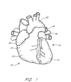
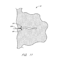
- a heart 10 is illustrated to show certain portions including the left ventricle 12, the left atrium 14, the left atrial appendage (LAA) 16, the pulmonary artery 18, the aorta 20, the right ventricle 22, the right atria 24, and the right atrial appendage 26.
- LAA left atrial appendage
- the left atrium 14 is located above the left ventricle 12 and the two are separated by the mitral valve (not illustrated).
- the LAA 16 is normally in fluid communication with the left atrium 14 such that blood flows in and out of the LAA 16 as the heart 10 beats.
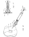
- a closure catheter 38 is advanced through the heart and into the LAA.
- the closure catheter 38 is adapted to grasp tissue surrounding the opening to the LAA, and retract it radially inwardly to reduce the volume of and/or close the LAA.
- the LAA is thereafter secured in its closed orientation, and the closure catheter 38 is removed. Specific aspects of one embodiment of the closure catheter in accordance with the present invention are described in greater detail below.
- the LAA may be accessed through any of a variety of pathways as will be apparent to those of skill in the art.
- Transeptal access may be achieved by introducing a transeptal catheter through the femoral or jugular vein, and transluminally advancing the catheter into the right atrium. Once in the right atrium, a long hollow needle with a preformed curve and a sharpened distal tip is forcibly inserted through the fossa ovalis. A radiopaque contrast media may then be injected through the needle to allow visualization and ensure placement of the needle in the left atrium, as opposed to being in the pericardial space, aorta, or other undesired location.
- the transeptal catheter is advanced into the left atrium.
- the closure catheter 38 may then be advanced through the transeptal catheter 30, and steered or directed into the left atrial appendage.
- Alternative approaches include venous transatrial approaches such as transvascular advancement through the aorta and the mitral valve.
- the devices of the present invention can be readily adapted for use in an open heart surgical procedure, although transluminal access is presently preferred.
- a transeptal catheter 30 has a proximal end 32 and a distal end 34.
- the distal end 34 of the transeptal catheter 30 has breached the septum 40 of the patient's heart 10 and is disposed adjacent the opening 42 of the patient's LAA 16.
- the distal end 36 of a closure catheter 38 extends from the distal end 34 of the transeptal catheter 30 and into the LAA 16.
- a luer connector coupled to a hemostasis valve 48 prevents the egress of blood from a central lumen of the transeptal catheter 30.
- the proximal end 50 of the closure catheter 38 extends proximally from the hemostasis valve 48. Additional details concerning the use and design of transeptal access catheters are well known in the art and will not be discussed further herein.
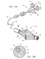
- the closure catheter 38 thus has a proximal end 50, a distal end 36, and an elongate flexible tubular body 52 extending therebetween.
- the axial length of the closure catheter 38 can be varied, depending upon the intended access point and pathway.
- the closure catheter 38 generally has an axial length within the range of from about 100 cm to about 140 cm, and, in one embodiment, about 117 cm.
- the outside diameter of the flexible body 52 can also be varied, depending upon the number of internal lumen and other functionalities as will be understood by those of skill in the art.
- the outside diameter is about 12 FR (.156 inches)
- closure catheters are contemplated to have OD's generally within the range about 2-6.3 mm (about .078 inches to about 0.250 inches). Diameters outside of the above range may also be used, provided that the functional consequences of the diameter are acceptable for the intended application of the catheter.
- the lower limit of the outside diameter for tubular body 52 in a given application will be a function of the number of fluid or other functional lumen contained within the catheter.
- tubular body 52 must have sufficient pushability to permit the catheter to be advanced to its target location within the heart without buckling or undesirable bending.
- the ability of the tubular body 52 to transmit torque may also be desirable, such as in embodiments in which the tissue anchor deployment guides are not uniformly circumferentially distributed about the distal end 36 of the catheter. Optimization of the outside diameter of the catheter, taking into account the flexibility, pushability and torque transmission characteristics can be accomplished through routine experimentation using conventional catheter design techniques well known to those of skill in the art.
- the flexible body 52 can be manufactured in accordance with any of a variety of known techniques.
- the flexible body 52 is extruded from any of a variety of materials such as HDPE, PEBAX, nylon, polyimide, and PEEK.
- at least a portion or all of the length of tubular body 52 may comprise a spring coil, solid walled hypodermic needle or other metal tubing, or braided reinforced wall, as are known in the art.
- the proximal end 50 of the closure catheter 38 is provided with a manifold 51, having a plurality of access ports.
- manifold 51 is provided with an access port 53 which may be used as a guidewire port in an over the wire embodiment, and a deployment wire port 57.
- Additional access ports such as a contrast media introduction port 55, or others may be provided as needed, depending upon the functional requirements of the catheter.
- the tubular body 52 has at least a first actuator lumen 54, for axially movably receiving an actuator 56.
- Actuator 56 extends between a proximal end 64 at about the proximal end of the closure catheter, and a distal end 66 at or near the distal end 36 of the closure catheter 38.
- the distal end 66 of the actuator 56 is secured to a cap 68.
- the actuator lumen 54 is in communication with the access port 53 to permit the actuator 56 to extend proximally therethrough.
- Actuator 56 can have a variety of forms, depending upon the construction of the anchor supports 62 on the distal end 36 of the closure catheter 38.
- the catheter in the area of the anchor supports 62 should have a crossing profile of no more than about 14 French for transluminal advancement and positioning.
- the anchor supports must then be capable of directing tissue anchors into the wall of the cavity or lumen which may have an inside diameter on the order of about 1.5 cm to about 3 cm in the case of the LAA in an average adult.
- the device of the present invention can be readily scaled up or down depending upon the intended use, such as to accommodate a 5 cm to 10 cm cavity in GI tract applications or 5 mm to about 2 cm for vascular applications.
- the anchor supports are preferably moveable between a reduced cross sectional orientation and an enlarged cross sectional orientation to aim at, and, in some embodiments, contact the target tissue surface.
- each anchor support 62 takes the form of a lever arm structure which is pivotably connected at one end to the catheter body. This construction permits inclination of the anchor support throughout a continuous range of outside diameters which may be desirable to aim the anchor and accommodate different treatment sites and/or normal anatomical variation within the patient population.
- a laterally moveable anchor support can be moved between an axial orientation and an inclined orientation in a variety of ways.
- One convenient way is through the use of a pull wire or other actuator which increases the diameter of the deployment zone of the catheter in response to an axial shortening of fixed length moveable segments as disclosed in more detail below.
- the actuator will be under pulling tension during actuation.
- Any of a variety of structures such as polymeric or metal single or multiple strand wires, ribbons or tubes can be used.
- the actuator 56 comprises stainless steel tube, having an outside diameter of about 0.6 mm (.025 inches).
- a pull wire can alternatively be connected to the radially outwardly facing surface and preferably near the distal end of each anchor support, and each anchor support is hingably attached at its proximal end to the catheter. Proximal traction on the pull wire will cause the anchor support to incline radially outwardly in the distal direction, and toward the target tissue.
- the anchor support is inclined under a compressive force on the actuator 56.
- the embodiment described in detail below can readily be converted to a push actuated system by axially immovably fixing the distal end of the anchor guide assembly to the catheter and slideably pushing the proximal end of the anchor guide assembly in the distal direction to achieve axial compression as will become apparent from the discussion below.
- Push wire actuators have different requirements, than pull actuator systems, such as the ability to propagate a sufficient compressive force without excessive compression bending or friction.
- solid core wires or tubular structures may be preferred, as well as larger outside diameters compared to the minimum requirements in a pull actuated system.
- the inside diameter of the actuator lumen 57 may be varied, depending upon the actuator system design.
- the actuator lumen 57 has an ID of about 1mm (.038 inches), to slideably accommodate the 0.6 mm (.025 inch) OD actuator 56.
- a radially outwardly directed force on the anchor supports 62 can be provided by any of a variety of alternative expansion structures, depending upon desired performance and construction issues.
- an inflatable balloon can be positioned radially inwardly from a plurality of hingably mounted anchor supports 62, and placed in communication with actuator lumen 54 which may be used as an inflation lumen.
- actuator lumen 54 which may be used as an inflation lumen.
- Any of a variety of balloon materials may be used, ranging in physical properties from latex for a highly compliant, low pressure system to PET for a noncompliant high pressure and consequently high radial force system, as is understood in the balloon angioplasty arts.
- the tubular body 52 may additionally be provided with a guidewire lumen 57, or a guidewire lumen 57 may extend coaxially throughout the length of a tubular actuator 56 as in the illustrated embodiment.
- the tubular body 52 may additionally be provided with a deployment lumen 58, for axially movably receiving one or more deployment elements 60 such as a wire, or suture for deploying one or more tissue anchors 90 into the target tissue 110.
- Deployment force for deploying the tissue anchors 90 can be designed to be in either the distal or proximal direction, and many of the considerations discussed above in connection with the actuator 56 and corresponding actuator lumen 54 apply to the deployment system as well.
- deployment of the tissue anchors 90 is accomplished by proximal retraction on the deployment element 60 which, in turn, retracts deployment wire 106. Pushability is thus not an issue, and common suture such as 0.2 mm (.008 inch) diameter nylon line may be used.
- deployment lumen 58 has an inside diameter of about 1mm (.038 inches).
- the deployment lumen 58 can be sized to receive either a single deployment element 60, or a plurality of deployment elements 106 such as a unique suture for each tissue anchor.
- the distal end 36 of the closure catheter 38 is provided with one or more anchor supports 62, for removably carrying one or more tissue anchors.
- anchor supports 62 Preferably, two or more anchor supports 62 are provided, and, generally, in a device intended for LAA closure, from about 3 to about 12 anchor supports 62 are provided. In the illustrated embodiment, six anchor supports 62 are evenly circumferentially spaced around the longitudinal axis of the closure catheter 38.
- Each anchor support 62 comprises a surface 63 for slideably retaining at least one tissue anchor, and permitting the tissue anchor to be aimed by manipulation of a control on the proximal end 50 of the closure catheter 38. Specific details of one embodiment of the anchor support 62 having a single anchor therein will be discussed below. Multiple anchors, such as two or three or more, can also be carried by each anchor support for sequential deployment.
- the anchor supports 62 are movable between an axial orientation and an inclined orientation, in response to manipulation of a proximal control.
- the proximal control can take any of a variety of forms, such as slider switches or levers, rotatable levers or knobs, or the like, depending upon the desired performance.
- a rotatable knob control can permit precise control over the degree of inclination of the anchor supports 62.
- a direct axial slider control, such as a knob or other grip directly mounted to the actuator 56 will optimize tactile feedback of events such as the anchor supports 62 coming into contact with the target tissue.
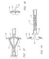
- Each of the illustrated anchor supports 62 comprises at least a proximal section 70, a distal section 72, and a flex point 74. See Figure 4.
- the distal end 73 of each distal section 72 is movably connected to the catheter body or the cap 68.
- proximal retraction of the actuator 56 shortens the axial distance between the proximal end 71 of the proximal section 70 and the distal end 73 of distal section 72, forcing the flex point 74 radially outwardly from the longitudinal axis of the closure catheter 38.
- proximal retraction of the actuator 56 through a controlled axial distance will cause a predictable and controlled increase in the angle between the proximal and distal sections 70 and 72 of the anchor support 62 and the longitudinal axis of the catheter.
- This is ideally suited for aiming a plurality of tissue anchors at the interior wall of a tubular structure, such as a vessel or the left atrial appendage.
- the proximal section 70 and distal section 72 preferably comprise a tubular wall 76 and 78 joined at the flex point 74.
- the proximal section 70 and distal section 72 may be formed from a single length of tubing, such as by laser cutting, photolithography, or grinding to separate the proximal section 70 from the distal section 72 while leaving one or two or more integrally formed hinges at flex point 74.
- Any of a variety of polymeric or metal tubing may be utilized for this purpose, including stainless steel, Nitinol or other super-elastic alloys, polyimide, or others which will be appreciated by those of skill in the art in view of the disclosure herein.
- the proximal section 70 and distal section 72 are formed from a length of PEEK tubing having an inside diameter of about 1mm (.038 inches), an outside diameter of about 1.14mm (.045 inches) and an overall length of about 36mm (1.4 inches). In general, if more than six anchor supports 62 are used, the diameter of each will be commensurately less than in the six tube embodiment for any particular application.
- a gap having an axial length of about 0.8mm (.030) is provided therebetween.
- the proximal section 70 and distal section 72 are approximately equal in length although dissimilar lengths may be desirable in certain embodiments.
- the length of the portion of the anchor support 62 which carries the tissue anchor 90 is preferably selected for a particular procedure or anatomy so that the anchor support 62 will be inclined at an acceptable launch angle when the deployment end of the anchor support 62 is brought into contact with the target tissue 110. Lengths from the hinge to the deployment end of the anchor support 62 within the range of from about 0.5 cm to about 1.5 cm are contemplated for the LAA application disclosed herein.
- the proximal section 70 is at least about 10% and preferably at least about 20% longer than the distal section 72.
- the proximal section 70 in a six anchor device has a length of about 14 mm (0.54 inches), and the distal section 72 has a length of about 10 mm (0.40 inches).
- Each anchor support has an OD of about 1.1mm (0.045 inches).
- the functional roles and/or the dimensions of the proximal and distal sections can be reversed and remain within the scope of the present invention. Optimization of the relative lever arm lengths can be determined for each application taking into account a variety of variables such as desired device diameter, target lumen or tissue aperture diameter, launch angle and desired pull forces for aiming and deployment.
- each anchor support 62 comprises a four segment component which may be constructed from a single length of tubing by providing an intermediate flex point 74, a proximal flex point 80 and a distal flex point 82.
- Distal flex point 82 provides a pivotable connection between the anchor support 62 and a distal connection segment 84.
- the distal connection segment 84 may be secured to the distal end of actuator 56 by any of a variety of techniques, such as soldering, adhesives, mechanical interfit or others, as will be apparent to those of skill in the art. In the illustrated embodiment, the distal connection segment 84 is secured to the distal end 66 of the actuator 56 by adhesive bonding.
- the proximal flex point 80 in the illustrated embodiment separates the proximal section 70 from a proximal connection segment 86, which is attached to the catheter body 52.
- proximal axial retraction of the actuator 56 with respect to the tubular body 52 will cause the distal connection segment 84 to advance proximally towards the proximal connection segment 86, thereby laterally displacing the flex point 74 away from the longitudinal axis of the closure catheter 38.
- each of the proximal section 70 and the distal section 72 are aimed at an angle which is inclined outwardly from the axis of the closure catheter 38.
- each flex point 80, 82 includes a hinge 81, 83 which may be, as illustrated, a strip of flexible material.
- the hinges 81 and 83 are preferably positioned on the inside radius of the flex points 80, 82, respectively, for many construction materials.
- the hinges 81 and 83 can be positioned at approximately 90° or 180° or other angle around the circumference of the tubular anchor guide from the inside radius of the flex point.
- a tissue anchor 90 is illustrated as positioned within the distal section 72, for deployment in a generally proximal direction. Alternatively, the anchor 90 can be loaded in the proximal section 70, for distal deployment.
- tissue anchors can be readily adapted for use with the closure catheter 38 of the present invention, as will be appreciated by those of skill in the art in view of the disclosure herein.
- the tissue anchor 90 comprises a tubular structure having a body 92, and one or more barbs 94.
- Tubular body 92 is coaxially movably disposed about an introducer 96.
- Introducer 96 has a proximal section 98, and a sharpened distal tip 100 separated by an elongate distal section 102 for slideably receiving the tissue anchor 90 thereon.
- the tissue anchor 90 in the illustrated embodiment comprises a tubular body 92 having an axial length of about 3mm (.118 inches), an inside diameter of about 0,43mm (.017 inches) and an outside diameter of about 0.58mm (.023 inches.
- Two or more barbs 94 may be provided by laser cutting a pattern in the wall of the tube, and bending each barb 94 such that it is biased radially outwardly as illustrated.
- the tissue anchor 90 may be made from any of a variety of biocompatible metals such as stainless steel, Nitinol, Elgiloy or others known in the art. Polymeric anchors such as HDPE, nylon, PTFE or others may alternatively be used.
- the anchor may comprise a bioabsorbable or dissolvable material so that it disappears after a period of time.
- An anchor suture 108 is secured to the anchor.
- the introducer 96 has an axial length of about 6.35 mm (.250 inches).
- the proximal section 98 has an outside diameter of about 0.6mm (.023 inches) and an axial length of about 2,5mm (.100 inches).
- the distal section 102 has an outside diameter of about 0.4mm (.016 inches) and an axial length of about 3.8mm (.150 inches.
- the outside diameter mismatch between the proximal section 98 and the distal section 102 provides a distally facing abutment 104, for supporting the tubular body 92 of tissue anchor 90, during the tissue penetration step.
- a deployment wire (e.g., a suture) 106 is secured to the proximal end 98 of the introducer 96.
- the introducer 96 may be made in any of a variety of ways, such as extrusion or machining from stainless steel tube stock.
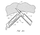
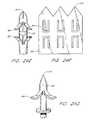
- tissue anchor 90 introduction of the tissue anchor 90 into target tissue 110 is illustrated following inclination of the anchor support 62 with respect to the longitudinal axis of the closure catheter 38.
- Proximal retraction of the deployment wire 106 causes the tissue anchor 90 and introducer 96 assembly to travel axially through the distal section 72, and into the tissue 110.
- Continued axial traction on the deployment wire 106 causes the longitudinal axis of the introducer 96 to rotate, such that the introducer 96 becomes coaxially aligned with the longitudinal axis of the proximal section 70.
- Continued proximal traction on the deployment wire 106 retracts the introducer 96 from the tissue anchor 90, leaving the tissue anchor 90 in place within the tissue.
- the anchor suture 108 remains secured to the tissue anchor 90, as illustrated in Figure 6C.
- the closure catheter 38 is percutaneously introduced into the vascular system and transluminally advanced into the heart and, subsequently, into the left atrial appendage using techniques which are known in the art.
- the distal end 36 of the closure catheter 38 is positioned at about the opening of the LAA 16, and the position may be confirmed using fluoroscopy, echocardiography, or other imaging.
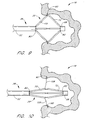
- the actuator 56 is thereafter proximally retracted, to incline the anchor supports 62 radially outwardly from the longitudinal axis of the closure catheter 38, as illustrated in Figure 8.
- the axial length of the proximal section 70 of each anchor support 62 in combination with the angular range of motion at the proximal flex point 80, permit the flex point 74 to be brought into contact with the tissue surrounding the opening to the LAA.
- this is preferably accomplished with the distal section 72 inclined at an angle within a range of from about 45° to about 120° with respect to the longitudinal axis of the closure catheter 38.
- Actuator 56 may be proximally retracted until the supports 62 are fully inclined, or until tactile feedback reveals that the anchor supports 62 have come into contact with the surrounding tissue 110.
- the deployment wire 106 is proximally retracted thereby advancing each of the tissue anchors 90 into the surrounding tissue 110 as has been discussed. See Fig. 9.
- the anchor supports 62 are thereafter returned to the first, axial position, as illustrated in Figure 10, for retraction from the left atrial appendage. Proximal retraction on the anchor sutures 108 such as through a tube, loop or aperture will then cause the left atrial appendage wall to collapse as illustrated in Figure 11.
- Anchor sutures may thereafter be secured together using any of a variety of conventional means, such as clips, knots, adhesives, or others which will be understood by those of skill in the art.
- the LAA may be sutured, pinned, stapled or clipped shut, or retained using any of a variety of biocompatible adhesives.
- a single suture 108 is slideably connected to the at least three and preferably five or more anchors such that proximal retraction of the suture 108 following deployment of the anchors draws the tissue closed in a "purse string" fashion.
- a similar technique is illustrated in Figures 31A and 31B in U.S. Patent No. 5,865,791 to Whayne , et al.,.
- anchors may be spaced around the circumference of the opening using any of the deployment catheters disclosed herein.
- the precise number and position of the anchors surrounding an atrial septal defect or other aperture can be varied depending upon the anatomy, and clinical judgement as will be apparent to those of skill in the art.
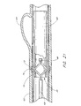
- FIG. 11A-11C the distal end 36 of a deployment catheter is schematically illustrated following deployment of a plurality of anchors 90. Only two anchors are illustrated for simplicity.
- An anchor suture 108 extends in a loop 113, and slideably carries each of the anchors 90.
- a retention structure 109 is slideably carried by first and second portions of the anchor suture 108, such that distal advancement of the retention structure 109 along the suture 108 causes the loop 113 formed by the distal portion of anchor suture 108 and retention structure 109 to decrease in circumference, such as would be accomplished during a reduction of the size of the tissue aperture or lumen.
- the retention structure 109 may be advanced distally along the suture 108 to close the loop 113 such as by proximally retracting the suture 108 into the deployment catheter and contacting the retention structure 109 against a distal surface 69 which may be on the cap 68 or other aspect of the distal end 36 of the catheter.
- the retention structure 109 includes a first Prusik knot 115 and a second Prusik knot 117, slideably carried on the suture 108.
- the first and second Prusik knots 115, 117 are secured together such as by a square knot 119. Any of a variety of other knots, links or other connections may alternatively be utilized.
- closure techniques may be accomplished through the closure catheter, or through the use of a separate catheter.
- the closure catheter may thereafter be proximally retracted from the patient, and the percutaneous and vascular access sites closed in accordance with conventional puncture closure techniques.
- the closure catheter 38 with modifications identified below and/or apparent to those of skill in the art in view of the intended application, may be utilized to close any of a variety of tissue apertures. These include, for example, atrial septal defects (ASD), ventricle septal defects (VSD), patent ductus arteriosis, patent foreman ovale, and others which will be apparent to those of skill in the art. Tissue aperture closure techniques will be discussed in general in connection with Figures 12-17.
- Tissue plane 120 such as a septum or other wall of the heart.
- Tissue plane 120 contains an aperture 122, which is desirably closed.
- the closure catheter 38 is illustrated such that at least a portion of the distal end 36 extends through the aperture 122.
- the proximal anchor advancement method may desirably assist in centering of the catheter within the aperture, as well as permitting positive traction to be in the same direction as anchor deployment.
- Closure catheter 38 is provided with a plurality of anchor supports 62 as have been described previously herein. In an embodiment intended for atrial septal defect closure, anywhere within the range of from about 3 to about 12 anchor supports 62 may be utilized.
- each anchor support 62 comprises a proximal section 70, a distal section 72, and a hinge or flex point 74 therebetween as has been previously discussed.
- At least one anchor 90 is carried by each anchor support 62, such as within the tubular distal section 72 in the context of a proximal deployment direction embodiment.
- Anchor 90 is connected to an anchor suture 108 as has been discussed.
- the anchor suture 108 extends along the outside of the anchor support 62 and into the distal opening of a lumen in tubular body 52.
- the anchor sutures 108 may, at some point, be joined into a single element, or distinct anchor sutures 108 may extend throughout the length of the catheter body to the proximal end thereof.
- the anchor support 62 is advanced from a generally axially extending orientation to an inclined orientation to facilitate deployment of the anchor 90 into the tissue plane 120 adjacent aperture 122.
- the geometry of the triangle defined by distal section 72, proximal section 70 and the longitudinal axis of the catheter is selected such that the plurality of anchors 90 will define a roughly circular pattern which has a greater diameter than the diameter of aperture 122.
- the length of proximal section 70 will generally be greater than the approximate radius of the aperture 122.
- the circle which best fits the anchor deployment pattern when the distal section 72 is inclined to its operative angle will have a diameter within the range of from about 0.5 centimeters to about 3 centimeters. Dimensions beyond either end of the foregoing range may be desirable to correct defects of unusual proportions.
- the anchors define a circular pattern when deployed into the tissue plane 120. Non-circular patterns such as polygonal, elliptical, oval or other, may be desirable, depending upon the nature of the aperture 122 to be closed.
- Figure 13 illustrates the anchors 90 partially deployed into or through the tissue plane 120.
- the anchors 90 may either be designed to reside within the tissue plane 120 such as for locations of the aperture 120 which are adjacent relatively thick tissues.
- the tissue anchor 90 may be designed to reside on one side of the tissue plane 120, and attached to a suture which extends through the tissue plane 120 as illustrated in Figures 14 and 15.
- the closure catheter 38 is illustrated as returned to the generally axial orientation and proximally retracted through the aperture 122 following deployment of a plurality of tissue anchors 90.
- the anchor sutures 108 may thereafter be proximally retracted from the proximal end of the closure catheter 38, thereby drawing the tissue surrounding aperture 122 together to close the aperture.
- the anchor sutures 108 may thereafter be secured together in any of a variety of manners, such as by clamping, knotting, adhesives, thermal bonding or the like.
- the closure catheter 38 carries a detachable clamp 124 which may be deployed from the distal end of the closure catheter 38 such as by a push wire, to retain the anchor sutures 108.
- the clamp 124 may be an annular structure with an aperture therein for receiving the anchor sutures 108.
- the clamp is carried on the catheter in an "open” position and biased towards a “closed” position in which it tightens around the sutures 108.
- a ring of elastomeric polymer, a relatively inelastic but tightenable loop such as a ligating band, or a shape memory metal alloy may be used for this purpose.
- Anchor sutures 108 may thereafter be severed such as by mechanical or thermal means, and the closure catheter 38 is thereafter retracted from the treatment site.
- elastic bands or other forms of the clamp may be deployed to directly clamp the tissue and hold the aperture closed.
- the closure catheter is used to attach a plurality of anchors spaced around the circumference of the aperture.
- the anchors are drawn radially inwardly towards each other by proximal traction on one or more sutures. Further proximal traction on the one or more sutures pulls the aperture edges proximally out of the tissue plane.
- the partially everted aperture can then be secured closed by deploying a clamp there around.
- clamp includes all of the elastic band, ligating band, metal clips and other embodiments disclosed herein.
- the closure catheter 38 is provided with a deployable patch 126, as illustrated in Figures 16 and 17.
- the patch 126 may comprise of any of a variety of materials, such as PTFE, Dacron, or others depending upon the intended use. Suitable fabrics are well-known in the medical device art, such as those used to cover endovascular grafts or other prosthetic devices.
- the patch 126 is preferably carried by the distal sections 72 of the anchor support 62.
- the tissue anchors 90 are carried within the proximal section 70 of anchor support 62.
- the patch 126 is automatically unfolded and positioned across the aperture 122 as the anchor supports 62 are inclined into the anchor deployment orientation.
- the tissue anchor 90 may thereafter be advanced through the patch 126 and into the tissue plane 120 to tack the patch 126 against the opening 122.
- the tissue anchors may be deployed in a pattern which surrounds but does not penetrate the tissue patch.
- the tissue anchors are preferably connected to the tissue patch such as by a suture.
- the tissue anchors may also both be connected to the patch or to each other by sutures and penetrated through the patch into the target tissue.
- Tissue anchors 90 may be deployed proximally by pulling the deployment wire 106.
- tissue anchors 90 with or without an anchor suture 108 may be deployed from the proximal section 70 by a push wire axially movably positioned within the proximal section 70.
- Tissue anchors 90 may be carried on an introducer 96 as has been discussed previously herein.
- the patch 126 may be retained on the distal section 72 in any of a variety of ways, such as through the use of low strength adhesive compositions, or by piercing the anchors 90 through the material of the patch 126 during the catheter assembly process.
- the anchor 90 may be utilized to anchor a suture within a solid tissue mass, or, as illustrated in Figure 20, to secure a graft or patch to a tissue plane.
- anchor 90 comprises a proximal end 130, a distal end 132 and a central lumen 134 extending therebetween.
- Central lumen 134 allows the anchor 90 to be positioned on an introducer 96 as is illustrated in Figure 19, and has been previously discussed.
- the anchor 90 is provided with at least a first proximal projection 136 and a second proximal projection 138.
- First and second proximal projections 136 and 138 are designed to enlarge radially outwardly in response to axial compression of the anchor 90.
- the first and second proximal projections 136 and 138 extend generally in parallel with the longitudinal axis of the anchor 90.
- a distally facing tissue contact surface 144 is forced to incline radially outwardly in response to axial shortening of the anchor 90, as will be apparent to those of skill in the art in view of the illustration in Figure 18.
- three or four or more proximal projections may be provided, preferably evenly distributed about the circumference of the anchor 90.
- At least a first distal projection 140, and preferably a second distal projection 142 are provided on the tubular body 92 spaced distally apart from the proximal projections.
- First and second distal projections 140 and 142 similarly expand or enlarge radially outwardly in response to axial compression of the anchor 90.
- Axial separation between the first proximal projection 136 and first distal projection 140 allows the anchor 90 to secure a patch 126 or graft or other structure to a tissue plane 120 as illustrated in Figure 20, by sandwiching the patch 126 and tissue plane 120 between distally facing tissue contact surface 144 and proximally facing tissue contact surface 146.
- the anchor 90 can be deployed from the introducer 96, utilizing any of the deployment catheters disclosed elsewhere herein.
- proximal and distal projections are accomplished by axially shortening the anchor 90 along its longitudinal axis. This may be accomplished by preventing proximal movement of proximal end 130 by seating the proximal end 130 against the proximal section 98 of an introducer 96, such as illustrated in Figure 19.
- the distal end 132 is thereafter advanced proximally, such as by proximal traction on a proximal force transmitter 148 which may be a suture 150.
- Suture 150 may extend in a loop through a plurality of apertures 152, extending through the proximal and distal projections. Alternatively, the suture 150 may extend alongside the anchor 90 or through central lumen 134 depending upon the tolerance between the central lumen 134 and the introducer 96.
- Alternative proximal force transmitter structures may also be utilized, as will be apparent to those of skill in the art.
- the anchor 90 may be manufactured in a variety of ways, such as by cutting or etching from a metal or polymeric tube.
- the anchor 90 is laser cut from a Nitinol or steel tube having an outside diameter within the range of from about 0.35mm (0.014") to about 1mm (0.038") and an axial length within the range of from about 1.3 mm (0.050") to about 6.3mm (0.250").
- the axial length of each of the distally facing tissue contact surface 144 and proximally facing tissue contact 146 is within the range of from about .25 mm (0.010") to about 1.5mm (0.060").
- the wall thickness of the tube is within the range of from about 50-300m (0.002" to about 0.012").
- the anchor 90 illustrated in Figure 18 may also be used to anchor a suture to a solid tissue mass as discussed previously herein.
- the anchor may be simplified to include only a first and second proximal projection 136 and 138, or additional projections in the same plane as the first and second proximal projections.
- first and second distal projections or additional projections may be added, depending upon the desired pull force required to dislodge the anchor 90 from the implanted position within the tissue.
- the cardiac defects may be accessed via catheter through a variety of pathways.
- An ASD or VSD may be accessed from the arterial circuit.
- the catheter is introduced into the arterial vascular system and guided up the descending thoracic and/or abdominal aorta.
- the catheter may then be advanced into the left ventricle (LV) through the aortic outflow tract.
- LV left ventricle
- the patch Once in the LV, the patch may be deployed in the VSD.
- the patch may be directed up through the mitral valve and into the left atrium (LA). When the patch is in the LA, it may be directed into the ASD and installed.
- LA left atrium
- an ASD or VSD may be accessed from the venous circuit.
- the catheter with a patch thereon may be introduced into the venous system, advanced into the Inferior Vena Cava (IVC) or Superior Vena Cava (SVC) and guided into the right atrium (RA).
- the patch may then be directed into the ASD.
- the patch may be advanced through the tricuspid valve and into the right ventricle (RV) and directed into the VSD and installed.
- the anchor deployment catheter of the present invention may also be readily used to accomplish any of a variety of anastomosis procedures, including attaching a synthetic vascular graft to an attachment site within a vessel, and performing tissue-to-tissue anastomosis of an autologous vein graft such as a graft of the saphenous vein into the coronary artery.
- the anastomosis catheter embodiment may also be utilized to provide intermediate support for a synthetic graft which has already been positioned at a treatment site in a vessel.
- FIG. 21 there is illustrated a schematic side elevational cross-section of a vessel 122 having a defect 124 such as an aneurysm.
- a graft 120 is illustrated spanning the defect 124, and overlapping at least a portion of healthy vessel wall both proximally and distally of the aneurysm 124.
- An anastomosis catheter 126 is illustrated in position within a proximal end of the graft 120.
- the anastomosis catheter 126 is provided with a plurality of anchor supports 62 near a distal end 36 thereof.
- Each anchor support comprises a proximal section 70, a distal section 72 and a hinge point 74.
- the graft 120 and vessel 122 have been penetrated by the sharpened tip 100 of an introducer 96, which has been deployed as discussed previously herein.
- the introducer 96 carries an anchor 92 thereon.
- proximal traction on a deployment wire which has previously been discussed causes the introducer 96 to introduce the anchor 92 into the treatment site.
- Continued traction on the deployment wire retracts the introducer 96 into the proximal section 70 of the anchor support 62, leaving the anchor 92 in position.
- the anchor 92 is provided with one or more distal barbs 94 for resisting proximal motion of the anchor 92, and one or more proximal barbs 95 for resisting distal migration of the anchor 92. In this manner, the anchor 92 will remain in position to secure the graft 120 to the vessel 122.
- the anastomosis catheter 126 can be adapted for use in a variety of graft implantation and attachment methods.
- a tubular graft which has been attached such as by the use of self expandable or balloon expandable stents at the proximal and distal ends of the graft may require intermediate support to maintain patency of the central lumen in between the axial ends.
- Intermediate support may be accomplished by either positioning additional stents within the tubular graft, or by using the anastomosis catheter 126 to anchor the graft to the native vessel wall. Two or more anchors may be provided in each anchor support.
- the anastomosis catheter 126 may be positioned at a first position where a first plurality of anchors are deployed through a graft into the native vessel, and then repositioned to a second position where a second plurality of anchors may be deployed to retain or secure the graft. Additional anchor supports and/or anchors may be provided on the anastomosis catheter 126, depending upon the number of anchors desirably positioned along the axial length of a graft.
- the anastomosis catheter 126 may be utilized to implant a tubular graft.
- the tubular graft is coaxially disposed about the exterior of the anastomosis catheter 126.
- the catheter is positioned at a treatment site, and the anchor supports are inclined to the axial orientation thereby positioning the vascular graft against the vessel wall.
- Anchors are deployed as has been discussed.
- the anchors may be secured to the graft directly such as through the use of a tether or other attachment structure, or may be independent from the graft but secured thereto in situ by the proximal and distal barbs or other structural arrangement which will become apparent to those of skill in the art in view of the disclosure herein.
- this embodiment of the invention may also be considered a transluminal graft implantation catheter or graft attachment catheter as will be apparent to those of skill in the art.
- FIGS 24A-24G there are illustrated a variety of tissue anchors which may be used in the tissue closure or attachment device of the present invention.
- Each of Figures 24A and 24B disclose an anchor having a body 92, a distal tip 101, and one or more barbs 94 to resist proximal movement of the anchor.
- An aperture 107 is provided to receive the anchor suture.
- the embodiments of Figure 24A and 24B can be readily manufactured such as by stamping or cutting out of flat sheet stock.
- the anchor illustrated in Figure 24C comprises a wire having a body 92 and a distal tip 101.
- the wire preferably comprises a super-elastic alloy such as Nitinol or other nickel titanium-based alloy.
- the anchor is carried within a tubular introducer, in a straight orientation, for introduction into the tissue where the anchor is to reside. As the body 92 is advanced distally from the carrier tube, the anchor resumes its looped distal end configuration within the tissue, to resist proximal retraction on the wire body 92.
- Figure 24D illustrates a tubular anchor, which may be manufactured from a section of hypotube, or in the form of a flat sheet which is thereafter rolled about a mandrel and soldered or otherwise secured.
- the anchor comprises a distal tip 101, one or more barbs 94, and an aperture 107 for securing the anchor suture.
- the anchor of Figure 24D may be carried by and deployed from the interior of a tubular anchor support as has been discussed.
- the anchor of Figure 24D can be coaxially positioned over a central tubular or solid anchor support wire.
- Figure 24E illustrates an anchor which may be formed either by cutting from tube stock or by cutting a flat sheet such as illustrated in Figure 24F which is thereafter rolled about an axis and soldered or otherwise secured into a tubular body.
- three distal tips 101 in the flat sheet stock may be formed into a single distal tip 101 in the finished anchor as illustrated in Figure 24E.
- One or more barbs 94 may be formed by slotting the sheet in a U or V-shaped configuration as illustrated.
- the anchor in Figure 24E is additionally provided with one or more barbs 95 which resist distal migration of the anchor. This may be desirable where the anchor is implanted across a thin membrane, or in other applications where distal as well as proximal migration is desirably minimized.
Landscapes
- Health & Medical Sciences (AREA)
- Surgery (AREA)
- Life Sciences & Earth Sciences (AREA)
- Medical Informatics (AREA)
- Animal Behavior & Ethology (AREA)
- Engineering & Computer Science (AREA)
- Biomedical Technology (AREA)
- Heart & Thoracic Surgery (AREA)
- Veterinary Medicine (AREA)
- Molecular Biology (AREA)
- Nuclear Medicine, Radiotherapy & Molecular Imaging (AREA)
- General Health & Medical Sciences (AREA)
- Public Health (AREA)
- Cardiology (AREA)
- Rheumatology (AREA)
- Reproductive Health (AREA)
- Vascular Medicine (AREA)
- Surgical Instruments (AREA)
- Prostheses (AREA)
Abstract
Description
- The present invention relates to methods and devices for closing a body lumen, tissue opening, or cavity and, in particular, for closing an atrial septal defect or the left atrial appendage. The invention also relates to methods and devices for performing anastomosis, in particular, for performing tissue-to-tissue or synthetic graft-to-tissue vascular anastomosis under either direct or transluminal access.
- Embolic stroke is the nation's third leading killer for adults, and is a major cause of disability. There are over 700,000 strokes per year in the United States alone. Of these, roughly 100,000 are hemoragic, and 600,000 are ischemic (either due to vessel narrowing or to embolism). The most common cause of embolic stroke emanating from the heart is thrombus formation due to atrial fibrillation. Approximately 80,000 strokes per year are attributable to atrial fibrillation. Atrial fibrillation is an arrhythmia of the heart that results in a rapid and chaotic heartbeat that produces lower cardiac output and irregular and turbulent blood flow in the vascular system. There are over five million people worldwide with atrial fibrillation, with about four hundred thousand new cases reported each year. Atrial fibrillation is associated with a 500 percent greater risk of stroke due to the condition. A patient with atrial fibrillation typically has a significantly decreased quality of life due, in part, to the fear of a stroke, and the pharmaceutical regimen necessary to reduce that risk.
- For patients who develop atrial thrombus from atrial fibrillation, the clot normally occurs in the left atrial appendage (LAA) of the heart. The LAA is a cavity which looks like a small finger or windsock and which is connected to the lateral wall of the left atrium between the mitral valve and the root of the left pulmonary vein. The LAA normally contracts with the rest of the left atrium during a normal heart cycle, thus keeping blood from becoming stagnant therein, but often fails to contract with any vigor in patients experiencing atrial fibrillation due to the discoordinate electrical signals associated with AF. As a result, thrombus formation is predisposed to form in the stagnant blood within the LAA.
- Blackshear and Odell have reported that of the 1288 patients with non-rheumatic atrial fibrillation involved in their study, 221 (17%) had thrombus detected in the left atrium of the heart. Blackshear JL, Odell JA., Appendage Obliteration to Reduce Stroke in Cardiac Surgical Patients with Atrial Fibrillation. Ann Thorac. Surg., 1996.61(2):755-9. Of the patients with atrial thrombus, 201 (91%) had the atrial thrombus located within the left atrial appendage. The foregoing suggests that the elimination or containment of thrombus formed within the LAA of patients with atrial fibrillation would significantly reduce the incidence of stroke in those patients.
- Pharmacological therapies for stroke prevention such as oral or systemic administration of warfarin or the like have been inadequate due to serious side effects of the medications and lack of patient compliance in taking the medication. Invasive surgical or thorascopic techniques have been used to obliterate the LAA, however, many patients are not suitable candidates for such surgical procedures due to a compromised condition or having previously undergone cardiac surgery. In addition, the perceived risks of even a thorascopic surgical procedure often outweigh the potential benefits. See Blackshear and Odell, above. See also Lindsay BD., Obliteration of the Left Atrial Appendage: A Concept Worth Testing, Ann Thorac. Surg., 1996.61 (2):515.
- Despite the various efforts in the prior art, there remains a need for a minimally invasive method and associated devices for reducing the risk of thrombus formation in the left atrial appendage.
- Other conditions which would benefit from a tissue aperture closure catheter are tissue openings such as an atrial septal defect. In general, the heart is divided into four chambers, the two upper being the left and right atria and the two lower being the left and right ventricles. The atria are separated from each other by a muscular wall, the interatrial septum, and the ventricles by the interventricular septum.
- Either congenitally or by acquisition, abnormal openings, holes or shunts can occur between the chambers of the heart or the great vessels (interatrial and interventricular septal defects or patent ductus arteriosus and aorthico-pulmonary window respectively), causing shunting of blood through the opening. The ductus arteriosus is the prenatal canal between the pulmonary artery and the aortic arch which normally closes soon after birth. The deformity is usually congenital, resulting from a failure of completion of the formation of the septum, or wall, between the two sides during fetal life when the heart forms from a folded tube into a four-chambered, two unit system.
- These deformities can carry significant sequelae. For example, with an atrial septal defect, blood is shunted from the left atrium of the heart to the right, producing an over-load of the right heart. In addition to left-to-right shunts such as occur in patent ductus arteriosus from the aorta to the pulmonary artery, the left side of the heart has to work harder because some of the blood which it pumps will recirculate through the lungs instead of going out to the rest of the body. The ill effects of these lesions usually cause added strain on the heart with ultimate failure if not corrected.
- Previous extracardiac (outside the heart) or intracardiac septal defects have required relatively extensive surgical techniques for correction. To date the most common method of closing intracardiac shunts, such as atrial-septal defects (ASD) and ventricular-septal defects (VSD), entails the relatively drastic technique of open-heart surgery, requiring opening the chest or sternum and diverting the blood from the heart with the use of a cardiopulmonary bypass. The heart is then opened, the defect is sewn shut by direct suturing with or without a patch of synthetic material (usually of Dacron, Teflon, silk, nylon or pericardium), and then the heart is closed. The patient is then taken off the cardiopulmonary bypass machine, and then the chest is closed.
- In place of direct suturing, closures of interauricular septal defects by means of a mechanical prosthesis have been disclosed.
-
U.S. Pat. No. 3,874,388 to King , et al. relates to a shunt defect closure system including a pair of opposed umbrella-like elements locked together in a face to face relationship and delivered by means of a catheter, whereby a defect is closed.U.S. Pat. No. 5,350,399 to Erlebacher , et al. relates to a percutaneous arterial puncture seal device also including a pair of opposed umbrella-like elements and an insertion tool. -
U.S. Pat. No. 4,710,192 to Liotta , et al. relates to a vaulted diaphragm for occlusion in a descending thoracic aorta. -
U.S. Pat. No. 5,108,420 to Marks relates to an aperture occlusion device consisting of a wire having an elongated configuration for delivery to the aperture, and a preprogrammed configuration including occlusion forming wire segments on each side of the aperture. -
U.S. Pat. No. 4,007,743 to Blake relates to an opening mechanism for umbrella-like intravascular shunt defect closure device having foldable flat ring sections which extend between pivotable struts when the device is expanded and fold between the struts when the device is collapsed. - Notwithstanding the foregoing, there remains a need for a transluminal method and apparatus for correcting intracardiac septal defects.
- Anastomosis is the union or joinder of one hollow vessel or structure to another so that the interior of the vessels communicate with one another. There are generally two types of vascular anastomosis: end-to-end and end-to-side. In an end-to-end anastomosis, the severed end of a first vessel or an end of a synthetic graft is coupled, usually by suturing or stapling, to the severed end of a second vessel. In the context of a synthetic vascular graft, the ends and possibly intermediate portions of the graft may be secured to the wall of the vessel without removing a portion of the native vessel. In an end-to-side anastomosis, the severed end of a first vessel or an end of a synthetic graft is connected around an opening cut into the side of a second vessel.
- Anastomoses are performed in a variety of anatomies, such as between airways, blood vessels, bowels, and urogenital lumens. The procedure for connecting blood vessels is referred to as vascular anastomosis. One of the best known surgical procedures utilizing vascular anastomosis is the coronary bypass. In the context of coronary artery disease, the flow of oxygenated blood to the myocardium of the heart is inhibited by a stenosis or obstruction in the coronary artery. This flow can be improved by providing a coronary artery bypass graft ("CABG") between the aorta and a point in the coronary artery distal to the stenosis. Typically, a section of vein from the leg is removed and attached at one end to the aorta and at the other end to the coronary artery utilizing end-to-side anastomosis. Such grafts are known as saphenous coronary artery bypass grafts. Alternatively, synthetic grafts can be utilized to effect the bypass.
- While the typical coronary bypass procedure favorably affects the incidence and severity of angina in patients with coronary artery disease, a variety of risks are associated with such procedures. Among them are mortality, myocardial infarction, postoperative bleeding, cerebrovascular accident, arrhythmias, wound or other infection, aortic dissection and limb ischemia. Furthermore, the vein grafts deteriorate over time, thereby resulting in the recurrence of angina, myocardial infarction and death. In addition, the costs of such procedures are relatively high and the patient recovery relatively long.
- In an attempt to overcome such problems, a number of alternative approaches have been developed. For example, artery to artery bypass procedures have been utilized in which an arterial source of oxygenated blood - such as the left internal mammary artery ("LIMA"), right internal mammary artery ("RIMA"), or right internal thoracic artery ("RITA") -- is severed and anastomosed to the obstructed coronary artery distally to the stenosis or occlusion. More recently, other arteries have been used in such procedures, including the inferior epigastria arteries and gastroepiploic arteries. In general, artery to artery bypass procedures have demonstrated a better patency rate as compared with autologous vein or synthetic grafts.
- While vascular anastomosis can be effective, and sometimes life-saving procedures, traditionally available techniques have been associated with a number of complications. For example, conventional techniques for performing vascular anastomosis generally require an extensive incision in the patient's body. Such operations are traumatic to the patient, involve a lengthy recovery, and a relatively high risk of infection or other complications.
- In the context of coronary bypass surgery, for example, the bypass graft or artery-to-artery procedure is traditionally performed using an open chest procedure. In particular, each procedure involves the necessity of a formal 20 to 25 cm incision in the chest of the patient, severing the sternum and cutting and peeling back various layers of tissue in order to give access to the heart and arterial sources. As a result, these operations typically require large numbers of sutures or staples to close the incision and 5 to 10 wire hooks to keep the severed sternum together. Furthermore, such procedures leave an unattractive scar and are painful to the patient. Most patients are out of work for a long period after such an operation and have restricted movement for several weeks. Such surgery often carries additional complications such as instability of the sternum, post-operative bleeding and mediastinal infection. Above all, open procedures are associated with long recuperation times.
- Due to the risks attendant to such procedures, there has been a need to develop procedures which minimize invasion of the patient's body tissue and resulting trauma. In this regard, limited open chest techniques have been developed in which the coronary bypass is carried out using an abdominal (subxyphoid) approach or, alternatively, a "Chamberlain" incision (an approximately 8 cm incision at the sternocostal junction), thereby lessening the operating area and the associated complication rate. While the risks attendant to such procedures are generally lower than their open chest counterparts, there is still a need for a minimally invasive surgical technique. Nevertheless, each of these techniques is thoracotomic, requiring an incision to be made in the chest wall through which conventional surgical instruments are introduced to perform conventional coronary bypass surgery.
- In order to reduce the risk of patient mortality, infection, and other complications associated with surgical techniques, it is advantageous and desirable to utilize endoscopic and thoracoscopic surgical techniques. Such procedures usually involve the use of surgical trocars to puncture the abdomen or chest, thereby facilitating access to a body cavity through the cannula and a relatively small opening in the patient's body. Typically, such trocars have a diameter of about 3 mm to 15 mm. Surgical instruments and other devices such as fiber optic cameras can be inserted into the body cavity through the cannula. Advantageously, the use of trocars minimizes the trauma associated with many surgical procedures.
- Another application involves the implantation and/or attachment of synthetic vascular grafts. Tubular vascular grafts comprising polytetrafluoroethylene (PTFE), Dacron, or other fabric materials may be implanted in a vessel to span a diseased or damaged site. In this application, the diseased portion of the vessel is merely isolated by directing blood flow through the graft. This may be accomplished by attaching the proximal end and distal end of the graft to the vessel wall proximally and distally of the diseased site. In some circumstances, portions of the graft in between the proximal and distal ends are preferably also attached to the vessel wall, to maintain patency throughout the graft One application of such grafts is to treat abdominal aortic aneurysms, by implanting either a straight segment graft or a Y shaped "bifurcation" graft at the bifurcation of the lower abdominal aorta and the left and right iliac arteries.
- When vascular anastomoses are performed, the goal is to achieve a sufficiently leak-proof connection between tubular structures. Typically, such connections in a CABG procedure are established using suturing techniques. Suturing of vascular structures, however, is a tedious and time consuming process. Furthermore, current suturing techniques are not possible using transluminal access, and are not readily adapted for endoscopic use, where the surgeon's freedom of access and movement are limited. Thus, there is a need for an alternative to current suturing techniques that would expedite the anastomosis procedure, and that can be readily adapted for transluminal or endoscopic use.
- Various stapling techniques are also known for providing anastomotic connections between organs, such as in intestinal and colorectal anastomosis. Due to the size of these devices, however, they are not easily adapted for use with vascular organs in general, and particularly not for transluminal or endoscopic techniques,
- Surgical clips have also been developed, which are intended to facilitate the anastomosis of vascular structures. In this technique, the vascular tissues are approximated, partially everted, and then clipped by applying the arms of the surgical clip over the everted tissue and securing the clip so as to hold the tissue together without penetrating the interior wall of the vessel. Nevertheless, in order to properly utilize these clips, the tissues should be everted. A transluminal approach is thus not readily possible using this technique.
-
WO 98/33462 - Thus, notwithstanding the various efforts in the prior art, there remains a need for methods and devices for performing vascular anastomoses, left atrial appendage or tissue opening closures which minimize the risk of infection, trauma, and other complications associated with conventional surgery, and, in particular, which can be utilized transluminally or in conjunction with an endoscopic technique for vascular anastomosis.
- The invention is defined in the accompanying independent claim. Dependent claims define preferred embodiments.
- Further features and advantages of the present invention will become apparent to those of skill in the art in view of the detailed description of preferred embodiments which follows, when considered together with the attached drawings and claims.
-
- Figure 1 is an anterior illustration of a heart, with the proximal parts of the great vessels.
- Figure 2 is a schematic cross section through the heart with a transeptal catheter deployed through the septum and a closure catheter extending into the LAA.
- Figure 3A is an enlarged perspective view of the distal end of a closure catheter in accordance with the present invention.
- Figure 3B is a cross section taken along the
fines 3B-3B of Figure 3A. - Figure 4 is a partial cross-sectional view of a tissue anchor and introducer, positioned within an anchor guide in accordance with the present invention.
- Figure 5 is an exploded view of a tissue anchor and introducer in accordance with one aspect of the invention.
- Figure 6A is a schematic illustration of a tissue anchor and introducer advancing into a tissue surface.
- Figure 6B is an illustration as in Figure 6A, with the anchor positioned within the tissue and the introducer partially retracted.
- Figure 6C is an illustration as in Figure 6B, with the introducer fully retracted and the anchor positioned within the tissue.
- Figure 7 shows a schematic view of a closure catheter disposed within the opening of the LAA.
- Figure 8 is a schematic illustration of the opening of the LAA as in Figure 7, with the anchor guides in an inclined orientation.
- Figure 9 is a schematic illustration as in Figure 8, with tissue anchors deployed from the anchor guides.
- Figure 10 is a schematic illustration as in Figure 9, with the anchor guides retracted into an axial orientation.
- Figure 11 is a schematic illustration as in Figure 10, with the closure catheter retracted and the LAA drawn closed using the tissue anchors.
- Figure 11A is a schematic illustration of the distal tip of a deployment catheter, having an anchor suture loop with a slideable retention structure thereon.
- Figure 11 B is a schematic illustration of a simplified Prusik knot, utilized as a component of the retention structure shown in Figure 11 A.
- Figure 11C is an enlargement of the retention structure shown in Figure 11A.
- Figure 12 is a perspective view of a closure catheter in accordance with the present invention positioned within a tissue aperture, such as an atrial septal defect.
- Figure 13 is a side elevational partial cross-section of the catheter of Figure 12, in an anchor deployment orientation within the aperture.
- Figure 14 is a side elevational partial cross-section as in Figure 13, with the deployment catheter withdrawn from the aperture.
- Figure 15 is a side elevational cross section through the aperture, which has been closed in accordance with the present invention.
- Figure 16 is a perspective view of a closure catheter in accordance with the present invention, carrying an aperture patch.
- Figure 17 is a cross-sectional view through the catheter of Figure 16, shown deploying a patch across a tissue aperture.
- Figure 18 is a perspective view of a buckling rivet type anchor in accordance with the present invention.
- Figure 19 is a perspective view of the buckling rivet of Figure 18, carried by an introducer.
- Figure 20 is a cross-sectional schematic view of a buckling rivet of the type shown in Figure 18, deployed on a tissue membrane.
- Figure 21 is a schematic cross-sectional view of an anastomosis catheter positioned within a synthetic tubular graft at a site in a body lumen.
- Figure 22 is a schematic illustration as in Figure 6A, with an anchor partially deployed through the graft and vessel wall.
- Figure 23 is a schematic illustration as in Figure 2, and similar to Figure 6C, showing the anastomosis anchor fully deployed.
- Figures 24A-24G are alternate tissue anchors for use with the closure catheter of the present invention.
- For simplicity, the present invention will be described primarily in the context of a left atrial appendage closure procedure. However, the device and methods herein are readily applicable to a wider variety of closure or attachment procedures, and all such applications are contemplated by the present inventors. For example, additional heart muscle procedures such as atrial septal defect closure and patent ductus arteriosis closure are contemplated. Vascular procedures such as isolation or repair of aneurysms, anastomosis of vessel to vessel or vessel to prosthetic tubular graft (e.g., PTFE or Dacron tubes, with or without wire support structures as are well known in the art) joints may also be accomplished using the devices of the present invention. Attachment of implantable prostheses, such as attachment of the annulus of a prosthetic tissue or mechanical heart valve may be accomplished. A variety of other tissue openings, lumens, hollow organs and surgically created passageways may be closed, patched or reduced in volume in accordance with the present invention. For example, an opening in a tissue plane may be closed or patched, such as by attaching a fabric or tissue sheet across the opening. In one specific application, the device of the present invention is used to anchor a fabric patch to close an atrial septal defect. The target aperture or cavity may be accessed transluminally (e.g., vascular catheter or endoscope) or through solid tissue, such as transmural, percutaneous or other approach. The present invention may also be used in an open surgical procedure such as to close the left atrial appendage during open heart surgery to correct or address a different condition. In another example, the device is advanced through the percutaneous opening and used to close a vascular puncture such as a femoral artery access site for a PTA or other diagnostic or therapeutic interventional procedure. Adaptation of the devices and methods disclosed herein to accomplish procedures such as the foregoing will be apparent to those of skill in the art in view of the disclosure herein.
- Referring to Figure 1, a
heart 10 is illustrated to show certain portions including theleft ventricle 12, theleft atrium 14, the left atrial appendage (LAA) 16, thepulmonary artery 18, theaorta 20, theright ventricle 22, theright atria 24, and the rightatrial appendage 26. As is understood in the art, theleft atrium 14 is located above theleft ventricle 12 and the two are separated by the mitral valve (not illustrated). TheLAA 16 is normally in fluid communication with theleft atrium 14 such that blood flows in and out of theLAA 16 as theheart 10 beats. - In accordance with the present invention, a
closure catheter 38 is advanced through the heart and into the LAA. In general, theclosure catheter 38 is adapted to grasp tissue surrounding the opening to the LAA, and retract it radially inwardly to reduce the volume of and/or close the LAA. The LAA is thereafter secured in its closed orientation, and theclosure catheter 38 is removed. Specific aspects of one embodiment of the closure catheter in accordance with the present invention are described in greater detail below. - The LAA may be accessed through any of a variety of pathways as will be apparent to those of skill in the art. Transeptal access, as contemplated by Figure 2, may be achieved by introducing a transeptal catheter through the femoral or jugular vein, and transluminally advancing the catheter into the right atrium. Once in the right atrium, a long hollow needle with a preformed curve and a sharpened distal tip is forcibly inserted through the fossa ovalis. A radiopaque contrast media may then be injected through the needle to allow visualization and ensure placement of the needle in the left atrium, as opposed to being in the pericardial space, aorta, or other undesired location.
- Once the position of the needle in the left atrium is confirmed, the transeptal catheter is advanced into the left atrium. The
closure catheter 38 may then be advanced through thetranseptal catheter 30, and steered or directed into the left atrial appendage. Alternative approaches include venous transatrial approaches such as transvascular advancement through the aorta and the mitral valve. In addition, the devices of the present invention can be readily adapted for use in an open heart surgical procedure, although transluminal access is presently preferred. - Thus, referring to Figure 2, a
transeptal catheter 30 has aproximal end 32 and adistal end 34. Thedistal end 34 of thetranseptal catheter 30 has breached theseptum 40 of the patient'sheart 10 and is disposed adjacent theopening 42 of the patient'sLAA 16. Thedistal end 36 of aclosure catheter 38 extends from thedistal end 34 of thetranseptal catheter 30 and into theLAA 16. - At the
proximal end 46 of thetranseptal catheter 30, a luer connector coupled to ahemostasis valve 48 prevents the egress of blood from a central lumen of thetranseptal catheter 30. Theproximal end 50 of theclosure catheter 38 extends proximally from thehemostasis valve 48. Additional details concerning the use and design of transeptal access catheters are well known in the art and will not be discussed further herein. - Referring to Figures 2 and 3, the
closure catheter 38 thus has aproximal end 50, adistal end 36, and an elongate flexibletubular body 52 extending therebetween. The axial length of theclosure catheter 38 can be varied, depending upon the intended access point and pathway. For a femoral vein-transeptal approach, theclosure catheter 38 generally has an axial length within the range of from about 100 cm to about 140 cm, and, in one embodiment, about 117 cm. - The outside diameter of the
flexible body 52 can also be varied, depending upon the number of internal lumen and other functionalities as will be understood by those of skill in the art. In one embodiment, the outside diameter is about 12 FR (.156 inches), and closure catheters are contemplated to have OD's generally within the range about 2-6.3 mm (about .078 inches to about 0.250 inches). Diameters outside of the above range may also be used, provided that the functional consequences of the diameter are acceptable for the intended application of the catheter. - For example, the lower limit of the outside diameter for
tubular body 52 in a given application will be a function of the number of fluid or other functional lumen contained within the catheter. In addition,tubular body 52 must have sufficient pushability to permit the catheter to be advanced to its target location within the heart without buckling or undesirable bending. The ability of thetubular body 52 to transmit torque may also be desirable, such as in embodiments in which the tissue anchor deployment guides are not uniformly circumferentially distributed about thedistal end 36 of the catheter. Optimization of the outside diameter of the catheter, taking into account the flexibility, pushability and torque transmission characteristics can be accomplished through routine experimentation using conventional catheter design techniques well known to those of skill in the art. - The
flexible body 52 can be manufactured in accordance with any of a variety of known techniques. In one embodiment, theflexible body 52 is extruded from any of a variety of materials such as HDPE, PEBAX, nylon, polyimide, and PEEK. Alternatively, at least a portion or all of the length oftubular body 52 may comprise a spring coil, solid walled hypodermic needle or other metal tubing, or braided reinforced wall, as are known in the art. - The
proximal end 50 of theclosure catheter 38 is provided with a manifold 51, having a plurality of access ports. Generally,manifold 51 is provided with anaccess port 53 which may be used as a guidewire port in an over the wire embodiment, and adeployment wire port 57. Additional access ports such as a contrastmedia introduction port 55, or others may be provided as needed, depending upon the functional requirements of the catheter. - The
tubular body 52 has at least afirst actuator lumen 54, for axially movably receiving anactuator 56.Actuator 56 extends between aproximal end 64 at about the proximal end of the closure catheter, and adistal end 66 at or near thedistal end 36 of theclosure catheter 38. Thedistal end 66 of theactuator 56 is secured to acap 68. In the illustrated embodiment, theactuator lumen 54 is in communication with theaccess port 53 to permit theactuator 56 to extend proximally therethrough. -
Actuator 56 can have a variety of forms, depending upon the construction of the anchor supports 62 on thedistal end 36 of theclosure catheter 38. In general, the catheter in the area of the anchor supports 62 should have a crossing profile of no more than about 14 French for transluminal advancement and positioning. However, the anchor supports must then be capable of directing tissue anchors into the wall of the cavity or lumen which may have an inside diameter on the order of about 1.5 cm to about 3 cm in the case of the LAA in an average adult. The device of the present invention can be readily scaled up or down depending upon the intended use, such as to accommodate a 5 cm to 10 cm cavity in GI tract applications or 5 mm to about 2 cm for vascular applications. For this purpose, the anchor supports are preferably moveable between a reduced cross sectional orientation and an enlarged cross sectional orientation to aim at, and, in some embodiments, contact the target tissue surface. - One convenient construction to accomplish the foregoing is for each
anchor support 62 to take the form of a lever arm structure which is pivotably connected at one end to the catheter body. This construction permits inclination of the anchor support throughout a continuous range of outside diameters which may be desirable to aim the anchor and accommodate different treatment sites and/or normal anatomical variation within the patient population. - A laterally moveable anchor support can be moved between an axial orientation and an inclined orientation in a variety of ways. One convenient way is through the use of a pull wire or other actuator which increases the diameter of the deployment zone of the catheter in response to an axial shortening of fixed length moveable segments as disclosed in more detail below. For this construction, the actuator will be under pulling tension during actuation. Any of a variety of structures such as polymeric or metal single or multiple strand wires, ribbons or tubes can be used. In the illustrated embodiment, the
actuator 56 comprises stainless steel tube, having an outside diameter of about 0.6 mm (.025 inches). - A pull wire can alternatively be connected to the radially outwardly facing surface and preferably near the distal end of each anchor support, and each anchor support is hingably attached at its proximal end to the catheter. Proximal traction on the pull wire will cause the anchor support to incline radially outwardly in the distal direction, and toward the target tissue.
- In an alternate construction, the anchor support is inclined under a compressive force on the
actuator 56. For example, the embodiment described in detail below can readily be converted to a push actuated system by axially immovably fixing the distal end of the anchor guide assembly to the catheter and slideably pushing the proximal end of the anchor guide assembly in the distal direction to achieve axial compression as will become apparent from the discussion below. - Push wire actuators have different requirements, than pull actuator systems, such as the ability to propagate a sufficient compressive force without excessive compression bending or friction. Thus, solid core wires or tubular structures may be preferred, as well as larger outside diameters compared to the minimum requirements in a pull actuated system. Thus, the inside diameter of the
actuator lumen 57 may be varied, depending upon the actuator system design. In the illustrated embodiment, theactuator lumen 57 has an ID of about 1mm (.038 inches), to slideably accommodate the 0.6 mm (.025 inch)OD actuator 56. - A radially outwardly directed force on the anchor supports 62 can be provided by any of a variety of alternative expansion structures, depending upon desired performance and construction issues. For example, an inflatable balloon can be positioned radially inwardly from a plurality of hingably mounted anchor supports 62, and placed in communication with
actuator lumen 54 which may be used as an inflation lumen. Any of a variety of balloon materials may be used, ranging in physical properties from latex for a highly compliant, low pressure system to PET for a noncompliant high pressure and consequently high radial force system, as is understood in the balloon angioplasty arts. - The
tubular body 52 may additionally be provided with aguidewire lumen 57, or aguidewire lumen 57 may extend coaxially throughout the length of atubular actuator 56 as in the illustrated embodiment. - The
tubular body 52 may additionally be provided with adeployment lumen 58, for axially movably receiving one ormore deployment elements 60 such as a wire, or suture for deploying one or more tissue anchors 90 into thetarget tissue 110. Deployment force for deploying the tissue anchors 90 can be designed to be in either the distal or proximal direction, and many of the considerations discussed above in connection with theactuator 56 andcorresponding actuator lumen 54 apply to the deployment system as well. In the illustrated embodiment, deployment of the tissue anchors 90 is accomplished by proximal retraction on thedeployment element 60 which, in turn, retractsdeployment wire 106. Pushability is thus not an issue, and common suture such as 0.2 mm (.008 inch) diameter nylon line may be used. For this embodiment,deployment lumen 58 has an inside diameter of about 1mm (.038 inches). Thedeployment lumen 58 can be sized to receive either asingle deployment element 60, or a plurality ofdeployment elements 106 such as a unique suture for each tissue anchor. - The
distal end 36 of theclosure catheter 38 is provided with one or more anchor supports 62, for removably carrying one or more tissue anchors. Preferably, two or more anchor supports 62 are provided, and, generally, in a device intended for LAA closure, from about 3 to about 12 anchor supports 62 are provided. In the illustrated embodiment, six anchor supports 62 are evenly circumferentially spaced around the longitudinal axis of theclosure catheter 38. - Each
anchor support 62 comprises asurface 63 for slideably retaining at least one tissue anchor, and permitting the tissue anchor to be aimed by manipulation of a control on theproximal end 50 of theclosure catheter 38. Specific details of one embodiment of theanchor support 62 having a single anchor therein will be discussed below. Multiple anchors, such as two or three or more, can also be carried by each anchor support for sequential deployment. - The anchor supports 62 are movable between an axial orientation and an inclined orientation, in response to manipulation of a proximal control. The proximal control can take any of a variety of forms, such as slider switches or levers, rotatable levers or knobs, or the like, depending upon the desired performance. For example, a rotatable knob control can permit precise control over the degree of inclination of the anchor supports 62. A direct axial slider control, such as a knob or other grip directly mounted to the
actuator 56 will optimize tactile feedback of events such as the anchor supports 62 coming into contact with the target tissue. - Each of the illustrated anchor supports 62 comprises at least a
proximal section 70, adistal section 72, and aflex point 74. See Figure 4. Thedistal end 73 of eachdistal section 72 is movably connected to the catheter body or thecap 68. In this embodiment, proximal retraction of theactuator 56 shortens the axial distance between theproximal end 71 of theproximal section 70 and thedistal end 73 ofdistal section 72, forcing theflex point 74 radially outwardly from the longitudinal axis of theclosure catheter 38. In this manner, proximal retraction of theactuator 56 through a controlled axial distance will cause a predictable and controlled increase in the angle between the proximal anddistal sections anchor support 62 and the longitudinal axis of the catheter. This is ideally suited for aiming a plurality of tissue anchors at the interior wall of a tubular structure, such as a vessel or the left atrial appendage. - Referring to Figure 4, there is illustrated an enlarged detailed view of one
anchor support 62 in accordance with the present invention. Theproximal section 70 anddistal section 72 preferably comprise atubular wall flex point 74. In one embodiment, theproximal section 70 anddistal section 72 may be formed from a single length of tubing, such as by laser cutting, photolithography, or grinding to separate theproximal section 70 from thedistal section 72 while leaving one or two or more integrally formed hinges atflex point 74. Any of a variety of polymeric or metal tubing may be utilized for this purpose, including stainless steel, Nitinol or other super-elastic alloys, polyimide, or others which will be appreciated by those of skill in the art in view of the disclosure herein. - In the illustrated six tube embodiment, the
proximal section 70 anddistal section 72 are formed from a length of PEEK tubing having an inside diameter of about 1mm (.038 inches), an outside diameter of about 1.14mm (.045 inches) and an overall length of about 36mm (1.4 inches). In general, if more than six anchor supports 62 are used, the diameter of each will be commensurately less than in the six tube embodiment for any particular application. When theproximal section 70 and thedistal section 72 are coaxially aligned, a gap having an axial length of about 0.8mm (.030) is provided therebetween. In the illustrated embodiment, theproximal section 70 anddistal section 72 are approximately equal in length although dissimilar lengths may be desirable in certain embodiments. The length of the portion of theanchor support 62 which carries thetissue anchor 90 is preferably selected for a particular procedure or anatomy so that theanchor support 62 will be inclined at an acceptable launch angle when the deployment end of theanchor support 62 is brought into contact with thetarget tissue 110. Lengths from the hinge to the deployment end of theanchor support 62 within the range of from about 0.5 cm to about 1.5 cm are contemplated for the LAA application disclosed herein. - For certain applications, the
proximal section 70 is at least about 10% and preferably at least about 20% longer than thedistal section 72. For example, in one device adapted for the LAA closure application, theproximal section 70 in a six anchor device has a length of about 14 mm (0.54 inches), and thedistal section 72 has a length of about 10 mm (0.40 inches). Each anchor support has an OD of about 1.1mm (0.045 inches). As with previous embodiments, the functional roles and/or the dimensions of the proximal and distal sections can be reversed and remain within the scope of the present invention. Optimization of the relative lever arm lengths can be determined for each application taking into account a variety of variables such as desired device diameter, target lumen or tissue aperture diameter, launch angle and desired pull forces for aiming and deployment. - The
proximal end 71 of theproximal section 70 anddistal end 73 ofdistal section 72 are movably secured to theclosure catheter 38 in any of a variety of ways which will be apparent to those of skill in the art in view of the disclosure herein. In the illustrated embodiment, eachanchor support 62 comprises a four segment component which may be constructed from a single length of tubing by providing anintermediate flex point 74, aproximal flex point 80 and adistal flex point 82.Distal flex point 82 provides a pivotable connection between theanchor support 62 and adistal connection segment 84. Thedistal connection segment 84 may be secured to the distal end ofactuator 56 by any of a variety of techniques, such as soldering, adhesives, mechanical interfit or others, as will be apparent to those of skill in the art. In the illustrated embodiment, thedistal connection segment 84 is secured to thedistal end 66 of theactuator 56 by adhesive bonding. - The
proximal flex point 80 in the illustrated embodiment separates theproximal section 70 from aproximal connection segment 86, which is attached to thecatheter body 52. In this construction, proximal axial retraction of theactuator 56 with respect to thetubular body 52 will cause thedistal connection segment 84 to advance proximally towards theproximal connection segment 86, thereby laterally displacing theflex point 74 away from the longitudinal axis of theclosure catheter 38. As a consequence, each of theproximal section 70 and thedistal section 72 are aimed at an angle which is inclined outwardly from the axis of theclosure catheter 38. - In general, each
flex point hinge hinges - A
tissue anchor 90 is illustrated as positioned within thedistal section 72, for deployment in a generally proximal direction. Alternatively, theanchor 90 can be loaded in theproximal section 70, for distal deployment. A variety of tissue anchors can be readily adapted for use with theclosure catheter 38 of the present invention, as will be appreciated by those of skill in the art in view of the disclosure herein. In the illustrated embodiment, thetissue anchor 90 comprises a tubular structure having abody 92, and one ormore barbs 94.Tubular body 92 is coaxially movably disposed about anintroducer 96.Introducer 96 has aproximal section 98, and a sharpeneddistal tip 100 separated by an elongatedistal section 102 for slideably receiving thetissue anchor 90 thereon. - The
tissue anchor 90 in the illustrated embodiment comprises atubular body 92 having an axial length of about 3mm (.118 inches), an inside diameter of about 0,43mm (.017 inches) and an outside diameter of about 0.58mm (.023 inches. Two ormore barbs 94 may be provided by laser cutting a pattern in the wall of the tube, and bending eachbarb 94 such that it is biased radially outwardly as illustrated. Thetissue anchor 90 may be made from any of a variety of biocompatible metals such as stainless steel, Nitinol, Elgiloy or others known in the art. Polymeric anchors such as HDPE, nylon, PTFE or others may alternatively be used. For embodiments which will rely upon a secondary closure structure such as staples, sutures or clips to retain the LAA or other cavity closed, the anchor may comprise a bioabsorbable or dissolvable material so that it disappears after a period of time. Ananchor suture 108 is secured to the anchor. - In one embodiment of the invention, the
introducer 96 has an axial length of about 6.35 mm (.250 inches). Theproximal section 98 has an outside diameter of about 0.6mm (.023 inches) and an axial length of about 2,5mm (.100 inches). Thedistal section 102 has an outside diameter of about 0.4mm (.016 inches) and an axial length of about 3.8mm (.150 inches. The outside diameter mismatch between theproximal section 98 and thedistal section 102 provides adistally facing abutment 104, for supporting thetubular body 92 oftissue anchor 90, during the tissue penetration step. A deployment wire (e.g., a suture) 106 is secured to theproximal end 98 of theintroducer 96. Theintroducer 96 may be made in any of a variety of ways, such as extrusion or machining from stainless steel tube stock. - Referring to Figures 6A-6C, introduction of the
tissue anchor 90 intotarget tissue 110 is illustrated following inclination of theanchor support 62 with respect to the longitudinal axis of theclosure catheter 38. Proximal retraction of thedeployment wire 106 causes thetissue anchor 90 andintroducer 96 assembly to travel axially through thedistal section 72, and into thetissue 110. Continued axial traction on thedeployment wire 106 causes the longitudinal axis of theintroducer 96 to rotate, such that theintroducer 96 becomes coaxially aligned with the longitudinal axis of theproximal section 70. Continued proximal traction on thedeployment wire 106 retracts theintroducer 96 from thetissue anchor 90, leaving thetissue anchor 90 in place within the tissue. Theanchor suture 108 remains secured to thetissue anchor 90, as illustrated in Figure 6C. - In use, the
closure catheter 38 is percutaneously introduced into the vascular system and transluminally advanced into the heart and, subsequently, into the left atrial appendage using techniques which are known in the art. Referring to Figure 7, thedistal end 36 of theclosure catheter 38 is positioned at about the opening of theLAA 16, and the position may be confirmed using fluoroscopy, echocardiography, or other imaging. Theactuator 56 is thereafter proximally retracted, to incline the anchor supports 62 radially outwardly from the longitudinal axis of theclosure catheter 38, as illustrated in Figure 8. Preferably, the axial length of theproximal section 70 of eachanchor support 62, in combination with the angular range of motion at theproximal flex point 80, permit theflex point 74 to be brought into contact with the tissue surrounding the opening to the LAA. In general, this is preferably accomplished with thedistal section 72 inclined at an angle within a range of from about 45° to about 120° with respect to the longitudinal axis of theclosure catheter 38.Actuator 56 may be proximally retracted until thesupports 62 are fully inclined, or until tactile feedback reveals that the anchor supports 62 have come into contact with the surroundingtissue 110. - Following inclination of the anchor supports 62, the
deployment wire 106 is proximally retracted thereby advancing each of the tissue anchors 90 into the surroundingtissue 110 as has been discussed. See Fig. 9. The anchor supports 62 are thereafter returned to the first, axial position, as illustrated in Figure 10, for retraction from the left atrial appendage. Proximal retraction on the anchor sutures 108 such as through a tube, loop or aperture will then cause the left atrial appendage wall to collapse as illustrated in Figure 11. Anchor sutures may thereafter be secured together using any of a variety of conventional means, such as clips, knots, adhesives, or others which will be understood by those of skill in the art. Alternatively, the LAA may be sutured, pinned, stapled or clipped shut, or retained using any of a variety of biocompatible adhesives. - In an alternate embodiment, a
single suture 108 is slideably connected to the at least three and preferably five or more anchors such that proximal retraction of thesuture 108 following deployment of the anchors draws the tissue closed in a "purse string" fashion. A similar technique is illustrated in Figures 31A and 31B inU.S. Patent No. 5,865,791 to Whayne , et al.,. - Depending upon the size and anatomical forces working on the aperture or lumen to be closed, anywhere from 2 to about 12 or more anchors may be spaced around the circumference of the opening using any of the deployment catheters disclosed herein. Preferably, from about 3 to about 8 anchors, and, in one "purse string" embodiment, six anchors are utilized in the context of closing an atrial septal defect. However, the precise number and position of the anchors surrounding an atrial septal defect or other aperture can be varied depending upon the anatomy, and clinical judgement as will be apparent to those of skill in the art.
- Referring to Figures 11A-11C the
distal end 36 of a deployment catheter is schematically illustrated following deployment of a plurality ofanchors 90. Only two anchors are illustrated for simplicity. Ananchor suture 108 extends in aloop 113, and slideably carries each of theanchors 90. Aretention structure 109 is slideably carried by first and second portions of theanchor suture 108, such that distal advancement of theretention structure 109 along thesuture 108 causes theloop 113 formed by the distal portion ofanchor suture 108 andretention structure 109 to decrease in circumference, such as would be accomplished during a reduction of the size of the tissue aperture or lumen. - Preferably, the
retention structure 109 may be advanced distally along thesuture 108 to close theloop 113 such as by proximally retracting thesuture 108 into the deployment catheter and contacting theretention structure 109 against adistal surface 69 which may be on thecap 68 or other aspect of thedistal end 36 of the catheter. In the illustrated embodiment, theretention structure 109 includes afirst Prusik knot 115 and asecond Prusik knot 117, slideably carried on thesuture 108. The first andsecond Prusik knots square knot 119. Any of a variety of other knots, links or other connections may alternatively be utilized. - The foregoing closure techniques may be accomplished through the closure catheter, or through the use of a separate catheter. The closure catheter may thereafter be proximally retracted from the patient, and the percutaneous and vascular access sites closed in accordance with conventional puncture closure techniques.
- In accordance with a further aspect of the present invention, the
closure catheter 38 with modifications identified below and/or apparent to those of skill in the art in view of the intended application, may be utilized to close any of a variety of tissue apertures. These include, for example, atrial septal defects (ASD), ventricle septal defects (VSD), patent ductus arteriosis, patent foreman ovale, and others which will be apparent to those of skill in the art. Tissue aperture closure techniques will be discussed in general in connection with Figures 12-17. - Referring to Figure 12, there is schematically illustrated a fragmentary view of a
tissue plane 120 such as a septum or other wall of the heart.Tissue plane 120 contains anaperture 122, which is desirably closed. Theclosure catheter 38 is illustrated such that at least a portion of thedistal end 36 extends through theaperture 122. Although the present aspect of the invention will be described in terms of a retrograde or proximal tissue anchor advancement from the back side of the tissue plane, the anchor deployment direction can readily be reversed by one of ordinary skill in the art in view of the disclosure herein, and the modifications to the associated method would be apparent in the context of a distal anchor advancement embodiment. In general, the proximal anchor advancement method, as illustrated, may desirably assist in centering of the catheter within the aperture, as well as permitting positive traction to be in the same direction as anchor deployment. -
Closure catheter 38 is provided with a plurality of anchor supports 62 as have been described previously herein. In an embodiment intended for atrial septal defect closure, anywhere within the range of from about 3 to about 12 anchor supports 62 may be utilized. - Referring to Figure 13, each
anchor support 62 comprises aproximal section 70, adistal section 72, and a hinge or flexpoint 74 therebetween as has been previously discussed. At least oneanchor 90 is carried by eachanchor support 62, such as within the tubulardistal section 72 in the context of a proximal deployment direction embodiment.Anchor 90 is connected to ananchor suture 108 as has been discussed. In the illustrated embodiment, theanchor suture 108 extends along the outside of theanchor support 62 and into the distal opening of a lumen intubular body 52. The anchor sutures 108 may, at some point, be joined into a single element, or distinct anchor sutures 108 may extend throughout the length of the catheter body to the proximal end thereof. - As shown in Figure 13, the
anchor support 62 is advanced from a generally axially extending orientation to an inclined orientation to facilitate deployment of theanchor 90 into thetissue plane 120adjacent aperture 122. Preferably, the geometry of the triangle defined bydistal section 72,proximal section 70 and the longitudinal axis of the catheter is selected such that the plurality ofanchors 90 will define a roughly circular pattern which has a greater diameter than the diameter ofaperture 122. Thus, the length ofproximal section 70 will generally be greater than the approximate radius of theaperture 122. - In general, for atrial septal defect applications, the circle which best fits the anchor deployment pattern when the
distal section 72 is inclined to its operative angle will have a diameter within the range of from about 0.5 centimeters to about 3 centimeters. Dimensions beyond either end of the foregoing range may be desirable to correct defects of unusual proportions. In addition, it is not necessary that the anchors define a circular pattern when deployed into thetissue plane 120. Non-circular patterns such as polygonal, elliptical, oval or other, may be desirable, depending upon the nature of theaperture 122 to be closed. - Figure 13 illustrates the
anchors 90 partially deployed into or through thetissue plane 120. In general, theanchors 90 may either be designed to reside within thetissue plane 120 such as for locations of theaperture 120 which are adjacent relatively thick tissues. Alternatively, thetissue anchor 90 may be designed to reside on one side of thetissue plane 120, and attached to a suture which extends through thetissue plane 120 as illustrated in Figures 14 and 15. - Referring to Figure 14, the
closure catheter 38 is illustrated as returned to the generally axial orientation and proximally retracted through theaperture 122 following deployment of a plurality of tissue anchors 90. The anchor sutures 108 may thereafter be proximally retracted from the proximal end of theclosure catheter 38, thereby drawing thetissue surrounding aperture 122 together to close the aperture. The anchor sutures 108 may thereafter be secured together in any of a variety of manners, such as by clamping, knotting, adhesives, thermal bonding or the like. - In the illustrated embodiment, the
closure catheter 38 carries adetachable clamp 124 which may be deployed from the distal end of theclosure catheter 38 such as by a push wire, to retain the anchor sutures 108. Theclamp 124 may be an annular structure with an aperture therein for receiving the anchor sutures 108. The clamp is carried on the catheter in an "open" position and biased towards a "closed" position in which it tightens around thesutures 108. A ring of elastomeric polymer, a relatively inelastic but tightenable loop such as a ligating band, or a shape memory metal alloy may be used for this purpose. Any of a variety of clamps, clips, adhesives, or other structures may be utilized to secure the anchor sutures 108 as will be appreciated by those of skill in the art in view of the disclosure herein. Anchor sutures 108 may thereafter be severed such as by mechanical or thermal means, and theclosure catheter 38 is thereafter retracted from the treatment site. - Alternatively, elastic bands or other forms of the clamp may be deployed to directly clamp the tissue and hold the aperture closed. In this application, the closure catheter is used to attach a plurality of anchors spaced around the circumference of the aperture. The anchors are drawn radially inwardly towards each other by proximal traction on one or more sutures. Further proximal traction on the one or more sutures pulls the aperture edges proximally out of the tissue plane. The partially everted aperture can then be secured closed by deploying a clamp there around. As used herein, "clamp" includes all of the elastic band, ligating band, metal clips and other embodiments disclosed herein.
- In accordance with a further aspect of the present invention, the
closure catheter 38 is provided with adeployable patch 126, as illustrated in Figures 16 and 17. Thepatch 126 may comprise of any of a variety of materials, such as PTFE, Dacron, or others depending upon the intended use. Suitable fabrics are well-known in the medical device art, such as those used to cover endovascular grafts or other prosthetic devices. - The
patch 126 is preferably carried by thedistal sections 72 of theanchor support 62. In the illustrated embodiment, the tissue anchors 90 are carried within theproximal section 70 ofanchor support 62. In this manner, as illustrated in Figure 17, thepatch 126 is automatically unfolded and positioned across theaperture 122 as the anchor supports 62 are inclined into the anchor deployment orientation. Thetissue anchor 90 may thereafter be advanced through thepatch 126 and into thetissue plane 120 to tack thepatch 126 against theopening 122. Alternatively, the tissue anchors may be deployed in a pattern which surrounds but does not penetrate the tissue patch. In this embodiment, the tissue anchors are preferably connected to the tissue patch such as by a suture. The tissue anchors may also both be connected to the patch or to each other by sutures and penetrated through the patch into the target tissue. - Tissue anchors 90 may be deployed proximally by pulling the
deployment wire 106. Alternatively, tissue anchors 90 with or without ananchor suture 108, may be deployed from theproximal section 70 by a push wire axially movably positioned within theproximal section 70. Tissue anchors 90 may be carried on anintroducer 96 as has been discussed previously herein. - The
patch 126 may be retained on thedistal section 72 in any of a variety of ways, such as through the use of low strength adhesive compositions, or by piercing theanchors 90 through the material of thepatch 126 during the catheter assembly process. - Referring to Figures 18 through 20, there is disclosed an
alternate anchor 90 in accordance with the present invention. Theanchor 90 may be utilized to anchor a suture within a solid tissue mass, or, as illustrated in Figure 20, to secure a graft or patch to a tissue plane. - Referring to Figure 18,
anchor 90 comprises aproximal end 130, adistal end 132 and acentral lumen 134 extending therebetween.Central lumen 134 allows theanchor 90 to be positioned on anintroducer 96 as is illustrated in Figure 19, and has been previously discussed. - The
anchor 90 is provided with at least a firstproximal projection 136 and a secondproximal projection 138. First and secondproximal projections anchor 90. Thus, in an uncompressed configuration such as that illustrated in Figure 19, the first and secondproximal projections anchor 90. A distally facingtissue contact surface 144 is forced to incline radially outwardly in response to axial shortening of theanchor 90, as will be apparent to those of skill in the art in view of the illustration in Figure 18. Although illustrated with two proximal projections positioned at approximately 180° apart from each other, three or four or more proximal projections may be provided, preferably evenly distributed about the circumference of theanchor 90. - At least a first
distal projection 140, and preferably a seconddistal projection 142 are provided on thetubular body 92 spaced distally apart from the proximal projections. First and seconddistal projections anchor 90. Axial separation between the firstproximal projection 136 and firstdistal projection 140 allows theanchor 90 to secure apatch 126 or graft or other structure to atissue plane 120 as illustrated in Figure 20, by sandwiching thepatch 126 andtissue plane 120 between distally facingtissue contact surface 144 and proximally facingtissue contact surface 146. Theanchor 90 can be deployed from theintroducer 96, utilizing any of the deployment catheters disclosed elsewhere herein. - The radial enlargement of the proximal and distal projections is accomplished by axially shortening the
anchor 90 along its longitudinal axis. This may be accomplished by preventing proximal movement ofproximal end 130 by seating theproximal end 130 against theproximal section 98 of anintroducer 96, such as illustrated in Figure 19. Thedistal end 132 is thereafter advanced proximally, such as by proximal traction on aproximal force transmitter 148 which may be asuture 150. Suture 150 may extend in a loop through a plurality ofapertures 152, extending through the proximal and distal projections. Alternatively, thesuture 150 may extend alongside theanchor 90 or throughcentral lumen 134 depending upon the tolerance between thecentral lumen 134 and theintroducer 96. Alternative proximal force transmitter structures may also be utilized, as will be apparent to those of skill in the art. - The
anchor 90 may be manufactured in a variety of ways, such as by cutting or etching from a metal or polymeric tube. Preferably, theanchor 90 is laser cut from a Nitinol or steel tube having an outside diameter within the range of from about 0.35mm (0.014") to about 1mm (0.038") and an axial length within the range of from about 1.3 mm (0.050") to about 6.3mm (0.250"). The axial length of each of the distally facingtissue contact surface 144 and proximally facingtissue contact 146 is within the range of from about .25 mm (0.010") to about 1.5mm (0.060"). The wall thickness of the tube is within the range of from about 50-300m (0.002" to about 0.012"). Full axial compression of most metal tube embodiments will bend the metal beyond its elastic limit at each apex on the various projections, such that thesuture 150 may be removed from the anchor 190 following deployment and the anchor will remain in its deployed (axially compressed) configuration as illustrated in Figure 20. - Although illustrated primarily as an embodiment intended for attaching a patch or other membrane to a tissue plane, the
anchor 90 illustrated in Figure 18 may also be used to anchor a suture to a solid tissue mass as discussed previously herein. For this purpose, the anchor may be simplified to include only a first and secondproximal projection anchor 90 from the implanted position within the tissue. - The cardiac defects may be accessed via catheter through a variety of pathways. An ASD or VSD may be accessed from the arterial circuit. The catheter is introduced into the arterial vascular system and guided up the descending thoracic and/or abdominal aorta. The catheter may then be advanced into the left ventricle (LV) through the aortic outflow tract. Once in the LV, the patch may be deployed in the VSD. Alternatively, once in the LV, the patch may be directed up through the mitral valve and into the left atrium (LA). When the patch is in the LA, it may be directed into the ASD and installed.
- Alternatively, an ASD or VSD may be accessed from the venous circuit. The catheter with a patch thereon may be introduced into the venous system, advanced into the Inferior Vena Cava (IVC) or Superior Vena Cava (SVC) and guided into the right atrium (RA). The patch may then be directed into the ASD. Alternatively, once in the RA, the patch may be advanced through the tricuspid valve and into the right ventricle (RV) and directed into the VSD and installed.
- The anchor deployment catheter of the present invention may also be readily used to accomplish any of a variety of anastomosis procedures, including attaching a synthetic vascular graft to an attachment site within a vessel, and performing tissue-to-tissue anastomosis of an autologous vein graft such as a graft of the saphenous vein into the coronary artery. The anastomosis catheter embodiment may also be utilized to provide intermediate support for a synthetic graft which has already been positioned at a treatment site in a vessel.
- Referring to Figure 21, there is illustrated a schematic side elevational cross-section of a
vessel 122 having adefect 124 such as an aneurysm. Agraft 120 is illustrated spanning thedefect 124, and overlapping at least a portion of healthy vessel wall both proximally and distally of theaneurysm 124. - An
anastomosis catheter 126 is illustrated in position within a proximal end of thegraft 120. Theanastomosis catheter 126 is provided with a plurality of anchor supports 62 near adistal end 36 thereof. Each anchor support comprises aproximal section 70, adistal section 72 and ahinge point 74. - Referring to Figure 22, the
graft 120 andvessel 122 have been penetrated by the sharpenedtip 100 of anintroducer 96, which has been deployed as discussed previously herein. The introducer 96 carries ananchor 92 thereon. In the illustrated embodiment, proximal traction on a deployment wire which has previously been discussed causes theintroducer 96 to introduce theanchor 92 into the treatment site. Continued traction on the deployment wire retracts theintroducer 96 into theproximal section 70 of theanchor support 62, leaving theanchor 92 in position. - As illustrated in Figure 23, the
anchor 92 is provided with one or moredistal barbs 94 for resisting proximal motion of theanchor 92, and one or moreproximal barbs 95 for resisting distal migration of theanchor 92. In this manner, theanchor 92 will remain in position to secure thegraft 120 to thevessel 122. - The
anastomosis catheter 126 can be adapted for use in a variety of graft implantation and attachment methods. For example, a tubular graft which has been attached such as by the use of self expandable or balloon expandable stents at the proximal and distal ends of the graft may require intermediate support to maintain patency of the central lumen in between the axial ends. Intermediate support may be accomplished by either positioning additional stents within the tubular graft, or by using theanastomosis catheter 126 to anchor the graft to the native vessel wall. Two or more anchors may be provided in each anchor support. In this manner, theanastomosis catheter 126 may be positioned at a first position where a first plurality of anchors are deployed through a graft into the native vessel, and then repositioned to a second position where a second plurality of anchors may be deployed to retain or secure the graft. Additional anchor supports and/or anchors may be provided on theanastomosis catheter 126, depending upon the number of anchors desirably positioned along the axial length of a graft. - Alternatively, the
anastomosis catheter 126 may be utilized to implant a tubular graft. In this embodiment, the tubular graft is coaxially disposed about the exterior of theanastomosis catheter 126. The catheter is positioned at a treatment site, and the anchor supports are inclined to the axial orientation thereby positioning the vascular graft against the vessel wall. Anchors are deployed as has been discussed. The anchors may be secured to the graft directly such as through the use of a tether or other attachment structure, or may be independent from the graft but secured thereto in situ by the proximal and distal barbs or other structural arrangement which will become apparent to those of skill in the art in view of the disclosure herein. Thus, although referred to generally herein as ananastomosis catheter 126, this embodiment of the invention may also be considered a transluminal graft implantation catheter or graft attachment catheter as will be apparent to those of skill in the art. - Referring to Figures 24A-24G, there are illustrated a variety of tissue anchors which may be used in the tissue closure or attachment device of the present invention. Each of Figures 24A and 24B disclose an anchor having a
body 92, adistal tip 101, and one ormore barbs 94 to resist proximal movement of the anchor. Anaperture 107 is provided to receive the anchor suture. The embodiments of Figure 24A and 24B can be readily manufactured such as by stamping or cutting out of flat sheet stock. - The anchor illustrated in Figure 24C comprises a wire having a
body 92 and adistal tip 101. The wire preferably comprises a super-elastic alloy such as Nitinol or other nickel titanium-based alloy. The anchor is carried within a tubular introducer, in a straight orientation, for introduction into the tissue where the anchor is to reside. As thebody 92 is advanced distally from the carrier tube, the anchor resumes its looped distal end configuration within the tissue, to resist proximal retraction on thewire body 92. - Figure 24D illustrates a tubular anchor, which may be manufactured from a section of hypotube, or in the form of a flat sheet which is thereafter rolled about a mandrel and soldered or otherwise secured. The anchor comprises a
distal tip 101, one ormore barbs 94, and anaperture 107 for securing the anchor suture. The anchor of Figure 24D may be carried by and deployed from the interior of a tubular anchor support as has been discussed. Alternatively, the anchor of Figure 24D can be coaxially positioned over a central tubular or solid anchor support wire. - Figure 24E illustrates an anchor which may be formed either by cutting from tube stock or by cutting a flat sheet such as illustrated in Figure 24F which is thereafter rolled about an axis and soldered or otherwise secured into a tubular body. In this embodiment, three
distal tips 101 in the flat sheet stock may be formed into a singledistal tip 101 in the finished anchor as illustrated in Figure 24E. One ormore barbs 94 may be formed by slotting the sheet in a U or V-shaped configuration as illustrated. The anchor in Figure 24E is additionally provided with one ormore barbs 95 which resist distal migration of the anchor. This may be desirable where the anchor is implanted across a thin membrane, or in other applications where distal as well as proximal migration is desirably minimized. - Although the present invention has been described in terms of certain preferred embodiments, other embodiments will become apparent to those of skill in the art in view of the disclosure herein. Accordingly, the scope of the invention is not intended to be limited by the specific disclosed embodiments, but, rather, by the attached claims.
Claims (26)
- A catheter (38) for deploying tissue anchors, (90) comprising:an elongate, flexible catheter body (52), having a proximal end (50) and a distal end (52), and a longitudinal axis extending therebetween;at least two anchor supports (62) on the distal end, each anchor support moveable between a first position in which it is substantially parallel with the axis, and a second position in which it is inclined laterally from the axis;a control on the body for moving the anchor supports from the axial orientation to the inclined orientation; andat least one anchor (90) supported by each anchor support;characterised in that the anchor supports each comprise a tube with at least one anchor positioned therein.
- A catheter as in Claim 1, comprising from two to eight anchor supports.
- A catheter as in Claim 1, comprising at least four tubes, each having a tissue anchor moveably positioned therein.
- A catheter as in any of the preceding claims, wherein the anchor supports each comprise a proximal section (70), a distal section (72), and a hinge (74) in between the proximal section and the distal section.
- A catheter as in Claim 4, further comprising an actuator (56,66) connected to the distal section, so that proximal retraction of the actuator with respect to the catheter body advances the anchor support from the first position towards the second position.
- A catheter as in Claim 4, wherein the control moves the hinge radially outwardly from a first position for introducing the catheter to a site in the body to a second position for deploying a patch at the site and wherein the supports are in the axial orientation when the hinge is in the first position.
- A catheter as in any of Claims 5 to 7, wherein at least on tissue anchor is carried by the proximal section of each support
- A catheter as in Claim 7, wherein the proximal section comprises a tube and the tissue anchor is removably carried inside of the tube.
- A catheter as in Claim 8, further comprising a deployment actuator (60) extending throughout the length of the catheter, and the tissue anchors are advanced distally out of the tubes in response to axial movement of the actuator.
- A catheter as in any of the preceding claims, further comprising at least one patch (126) carried by the distal section of each support.
- A catheter as in Claim 10, comprising a tissue ingrowth surface on the patch.
- A closure catheter as in any of the preceding claims, further comprising an inflatable balloon, wherein inflation of the balloon advances the anchor supports from the first position to the second position.
- A catheter as in any of the preceding claims, wherein the anchor support is biased toward the inclined orientation.
- A catheter as in any of the preceding claims, wherein the control comprises an axially moveable actuator, wherein the actuator comprises a core connected to the anchor support such that proximal retraction of the core advance the anchor support from the axial orientation to the inclined orientation.
- A catheter as in any of the preceding claims, further comprising an introducer removably connected to the anchor for driving the anchor into tissue.
- A catheter as in Claim 15, wherein the anchor comprises a tubular body and the introducer extends axially therethrough.
- A catheter as in any of Claims 1 to 14, further comprising an introducer, slideably carried by the anchor support and a tissue anchor removably connected to the introducer.
- A catheter as in Claim 17, wherein the introducer comprises an elongate body having a sharpened distal end (100), and the tissue anchor is coaxilly positioned on the body.
- A catheter as in Claim 17, further comprising a deployment line connected to the introducer.
- A catheter as in any of the preceding claims, comprising at least two anchors and wherein each anchor support has a proximal end and a distal end, and the distal end is pivotably secured to the catheter so that the proximal end moves away from the axis when the anchor support is moved into the inclined position,
- A catheter as in any of the preceding claims, further comprising a suture connected to each anchor.
- A catheter as in any of the preceding claims, further comprising a claim (124) removably carried by the distal end of the catheter.
- A catheter as in any of the preceding claims, wherein the anchor comprises:a body (92), having a proximal end, a distal end, and a longitudinal axis;at least on proximal arm on the body for resisting distal movement of the anchor through tissue; andat least one distal arm on the body for resisting proximal movement of the anchor through tissue;wherein the proximal and distal arms are moveable between a first position in which the cross section of the anchor is minimized and a second position in which the arms are deployed.
- A catheter as in Claim 23, wherein the arms of the anchor are biased in the direction of the second position.
- A catheter as in Claim 23 or Claim 24, wherein the arms of the anchor are moveable into the second position in response to axial shortening of the anchor.
- A catheter as in any of Claims 23 to 25, wherein the arms and body of the anchor are integrally formed from a tube.
Priority Applications (1)
| Application Number | Priority Date | Filing Date | Title |
|---|---|---|---|
| EP07015361A EP1852141A3 (en) | 1999-09-20 | 2000-09-20 | Apparatus for closing a body lumen |
Applications Claiming Priority (9)
| Application Number | Priority Date | Filing Date | Title |
|---|---|---|---|
| US447390 | 1989-12-07 | ||
| US399521 | 1999-09-20 | ||
| US09/399,521 US6231561B1 (en) | 1999-09-20 | 1999-09-20 | Method and apparatus for closing a body lumen |
| US09/444,904 US6290674B1 (en) | 1999-09-20 | 1999-11-22 | Method and apparatus for closing intracardiac septal defects |
| US09/447,390 US6419669B1 (en) | 1999-09-20 | 1999-11-22 | Method and apparatus for patching a tissue opening |
| US444904 | 1999-11-22 | ||
| US09/482,986 US6328727B1 (en) | 1999-09-20 | 2000-01-11 | Transluminal anastomosis method and apparatus |
| US482986 | 2000-01-11 | ||
| PCT/US2000/025840 WO2001021247A1 (en) | 1999-09-20 | 2000-09-20 | Method and apparatus for closing a body lumen |
Related Child Applications (1)
| Application Number | Title | Priority Date | Filing Date |
|---|---|---|---|
| EP07015361A Division EP1852141A3 (en) | 1999-09-20 | 2000-09-20 | Apparatus for closing a body lumen |
Publications (3)
| Publication Number | Publication Date |
|---|---|
| EP1225948A1 EP1225948A1 (en) | 2002-07-31 |
| EP1225948A4 EP1225948A4 (en) | 2004-11-10 |
| EP1225948B1 true EP1225948B1 (en) | 2007-08-08 |
Family
ID=27503436
Family Applications (1)
| Application Number | Title | Priority Date | Filing Date |
|---|---|---|---|
| EP00965226A Expired - Lifetime EP1225948B1 (en) | 1999-09-20 | 2000-09-20 | Apparatus for closing a body lumen |
Country Status (8)
| Country | Link |
|---|---|
| EP (1) | EP1225948B1 (en) |
| JP (1) | JP2003509175A (en) |
| CN (1) | CN1236733C (en) |
| AT (1) | ATE369178T1 (en) |
| AU (1) | AU771470B2 (en) |
| CA (1) | CA2383595A1 (en) |
| ES (1) | ES2293922T3 (en) |
| WO (1) | WO2001021247A1 (en) |
Cited By (17)
| Publication number | Priority date | Publication date | Assignee | Title |
|---|---|---|---|---|
| US10856984B2 (en) | 2017-08-25 | 2020-12-08 | Neovasc Tiara Inc. | Sequentially deployed transcatheter mitral valve prosthesis |
| US10940001B2 (en) | 2012-05-30 | 2021-03-09 | Neovasc Tiara Inc. | Methods and apparatus for loading a prosthesis onto a delivery system |
| US11311376B2 (en) | 2019-06-20 | 2022-04-26 | Neovase Tiara Inc. | Low profile prosthetic mitral valve |
| US11357622B2 (en) | 2016-01-29 | 2022-06-14 | Neovase Tiara Inc. | Prosthetic valve for avoiding obstruction of outflow |
| US11389291B2 (en) | 2013-04-04 | 2022-07-19 | Neovase Tiara Inc. | Methods and apparatus for delivering a prosthetic valve to a beating heart |
| US11413139B2 (en) | 2011-11-23 | 2022-08-16 | Neovasc Tiara Inc. | Sequentially deployed transcatheter mitral valve prosthesis |
| US11419720B2 (en) | 2010-05-05 | 2022-08-23 | Neovasc Tiara Inc. | Transcatheter mitral valve prosthesis |
| US11464631B2 (en) | 2016-11-21 | 2022-10-11 | Neovasc Tiara Inc. | Methods and systems for rapid retraction of a transcatheter heart valve delivery system |
| US11491006B2 (en) | 2019-04-10 | 2022-11-08 | Neovasc Tiara Inc. | Prosthetic valve with natural blood flow |
| US11497602B2 (en) | 2012-02-14 | 2022-11-15 | Neovasc Tiara Inc. | Methods and apparatus for engaging a valve prosthesis with tissue |
| US11602429B2 (en) | 2019-04-01 | 2023-03-14 | Neovasc Tiara Inc. | Controllably deployable prosthetic valve |
| US11737872B2 (en) | 2018-11-08 | 2023-08-29 | Neovasc Tiara Inc. | Ventricular deployment of a transcatheter mitral valve prosthesis |
| US11779742B2 (en) | 2019-05-20 | 2023-10-10 | Neovasc Tiara Inc. | Introducer with hemostasis mechanism |
| US11812945B2 (en) | 2019-09-26 | 2023-11-14 | Medos International Sarl | One-way adjustable loop suture constructs and methods of forming and using the same |
| US11998447B2 (en) | 2019-03-08 | 2024-06-04 | Neovasc Tiara Inc. | Retrievable prosthesis delivery system |
| US12109111B2 (en) | 2015-12-15 | 2024-10-08 | Neovasc Tiara Inc. | Transseptal delivery system |
| US12138159B2 (en) | 2022-10-13 | 2024-11-12 | Neovasc Tiara Inc. | Methods and apparatus for engaging a valve prosthesis with tissue |
Families Citing this family (114)
| Publication number | Priority date | Publication date | Assignee | Title |
|---|---|---|---|---|
| US7883539B2 (en) | 1997-01-02 | 2011-02-08 | Edwards Lifesciences Llc | Heart wall tension reduction apparatus and method |
| US6332893B1 (en) | 1997-12-17 | 2001-12-25 | Myocor, Inc. | Valve to myocardium tension members device and method |
| US6260552B1 (en) | 1998-07-29 | 2001-07-17 | Myocor, Inc. | Transventricular implant tools and devices |
| US7662161B2 (en) | 1999-09-13 | 2010-02-16 | Rex Medical, L.P | Vascular hole closure device |
| US6231561B1 (en) | 1999-09-20 | 2001-05-15 | Appriva Medical, Inc. | Method and apparatus for closing a body lumen |
| US6689150B1 (en) | 1999-10-27 | 2004-02-10 | Atritech, Inc. | Filter apparatus for ostium of left atrial appendage |
| US6723038B1 (en) | 2000-10-06 | 2004-04-20 | Myocor, Inc. | Methods and devices for improving mitral valve function |
| US6896692B2 (en) | 2000-12-14 | 2005-05-24 | Ensure Medical, Inc. | Plug with collet and apparatus and method for delivering such plugs |
| US8083768B2 (en) | 2000-12-14 | 2011-12-27 | Ensure Medical, Inc. | Vascular plug having composite construction |
| US6890343B2 (en) | 2000-12-14 | 2005-05-10 | Ensure Medical, Inc. | Plug with detachable guidewire element and methods for use |
| US6846319B2 (en) | 2000-12-14 | 2005-01-25 | Core Medical, Inc. | Devices for sealing openings through tissue and apparatus and methods for delivering them |
| US6623509B2 (en) | 2000-12-14 | 2003-09-23 | Core Medical, Inc. | Apparatus and methods for sealing vascular punctures |
| US20060052821A1 (en) | 2001-09-06 | 2006-03-09 | Ovalis, Inc. | Systems and methods for treating septal defects |
| US6702835B2 (en) * | 2001-09-07 | 2004-03-09 | Core Medical, Inc. | Needle apparatus for closing septal defects and methods for using such apparatus |
| US6776784B2 (en) | 2001-09-06 | 2004-08-17 | Core Medical, Inc. | Clip apparatus for closing septal defects and methods of use |
| US20050177180A1 (en) * | 2001-11-28 | 2005-08-11 | Aptus Endosystems, Inc. | Devices, systems, and methods for supporting tissue and/or structures within a hollow body organ |
| US7318833B2 (en) | 2001-12-19 | 2008-01-15 | Nmt Medical, Inc. | PFO closure device with flexible thrombogenic joint and improved dislodgement resistance |
| US6764510B2 (en) | 2002-01-09 | 2004-07-20 | Myocor, Inc. | Devices and methods for heart valve treatment |
| JP4328209B2 (en) | 2002-01-25 | 2009-09-09 | アトリテック, インコーポレイテッド | Atrial appendage blood filtration system |
| WO2003082076A2 (en) | 2002-03-25 | 2003-10-09 | Nmt Medical, Inc. | Patent foramen ovale (pfo) closure clips |
| US7976564B2 (en) * | 2002-05-06 | 2011-07-12 | St. Jude Medical, Cardiology Division, Inc. | PFO closure devices and related methods of use |
| WO2003103476A2 (en) | 2002-06-05 | 2003-12-18 | Nmt Medical, Inc. | Patent foramen ovale (pfo) closure device with radial and circumferential support |
| EP1521550A4 (en) | 2002-06-12 | 2011-02-23 | Mitral Interventions Inc | Method and apparatus for tissue connection |
| US7112219B2 (en) | 2002-11-12 | 2006-09-26 | Myocor, Inc. | Devices and methods for heart valve treatment |
| WO2004052213A1 (en) | 2002-12-09 | 2004-06-24 | Nmt Medical, Inc. | Septal closure devices |
| US8562646B2 (en) * | 2002-12-19 | 2013-10-22 | Boston Scientific Scimed, Inc. | Anchoring to soft tissue |
| CA2532112C (en) | 2003-07-14 | 2012-09-18 | Nmt Medical, Inc. | Tubular patent foramen ovale (pfo) closure device with catch system |
| US9861346B2 (en) | 2003-07-14 | 2018-01-09 | W. L. Gore & Associates, Inc. | Patent foramen ovale (PFO) closure device with linearly elongating petals |
| US8480706B2 (en) | 2003-07-14 | 2013-07-09 | W.L. Gore & Associates, Inc. | Tubular patent foramen ovale (PFO) closure device with catch system |
| EP1670360B1 (en) | 2003-09-12 | 2007-10-17 | NMT Medical, Inc. | Device for preventing formation of thrombi in the left atrial appendage |
| US8852229B2 (en) | 2003-10-17 | 2014-10-07 | Cordis Corporation | Locator and closure device and method of use |
| US7361183B2 (en) | 2003-10-17 | 2008-04-22 | Ensure Medical, Inc. | Locator and delivery device and method of use |
| EP1557193B1 (en) | 2004-01-22 | 2008-03-05 | Nipro Corporation | Balloon catheter |
| JP2007526087A (en) | 2004-03-03 | 2007-09-13 | エヌエムティー メディカル, インコーポレイティッド | Delivery / recovery system for septal occluder |
| US7806846B2 (en) | 2004-03-30 | 2010-10-05 | Nmt Medical, Inc. | Restoration of flow in LAA via tubular conduit |
| US20050228413A1 (en) * | 2004-04-12 | 2005-10-13 | Binmoeller Kenneth F | Automated transluminal tissue targeting and anchoring devices and methods |
| US8425539B2 (en) * | 2004-04-12 | 2013-04-23 | Xlumena, Inc. | Luminal structure anchoring devices and methods |
| US8308760B2 (en) | 2004-05-06 | 2012-11-13 | W.L. Gore & Associates, Inc. | Delivery systems and methods for PFO closure device with two anchors |
| EP1748732A1 (en) | 2004-05-07 | 2007-02-07 | NMT Medical, Inc. | Catching mechanisms for tubular septal occluder |
| US8328837B2 (en) | 2004-12-08 | 2012-12-11 | Xlumena, Inc. | Method and apparatus for performing needle guided interventions |
| JP4629445B2 (en) * | 2005-01-11 | 2011-02-09 | テルモ株式会社 | In vivo tissue closure device and in vivo tissue closure device |
| US8926654B2 (en) | 2005-05-04 | 2015-01-06 | Cordis Corporation | Locator and closure device and method of use |
| US8088144B2 (en) | 2005-05-04 | 2012-01-03 | Ensure Medical, Inc. | Locator and closure device and method of use |
| US8777967B2 (en) | 2005-06-09 | 2014-07-15 | Xlumena, Inc. | Methods and devices for anchoring to tissue |
| US8784437B2 (en) | 2005-06-09 | 2014-07-22 | Xlumena, Inc. | Methods and devices for endosonography-guided fundoplexy |
| US8579936B2 (en) | 2005-07-05 | 2013-11-12 | ProMed, Inc. | Centering of delivery devices with respect to a septal defect |
| US7846179B2 (en) | 2005-09-01 | 2010-12-07 | Ovalis, Inc. | Suture-based systems and methods for treating septal defects |
| AU2006287211B2 (en) | 2005-09-01 | 2012-09-27 | Cardinal Health 529, Llc | Patent foramen ovale closure method |
| US9259267B2 (en) | 2005-09-06 | 2016-02-16 | W.L. Gore & Associates, Inc. | Devices and methods for treating cardiac tissue |
| US20070167981A1 (en) | 2005-12-22 | 2007-07-19 | Nmt Medical, Inc. | Catch members for occluder devices |
| JP4624466B2 (en) * | 2006-01-01 | 2011-02-02 | シフリン、エドワード ジー. | Apparatus and method for vascular graft or stent graft delivery and fixation at both ends |
| US8870913B2 (en) | 2006-03-31 | 2014-10-28 | W.L. Gore & Associates, Inc. | Catch system with locking cap for patent foramen ovale (PFO) occluder |
| AU2007257785B2 (en) | 2006-06-09 | 2013-05-02 | Cardinal Health 529, Llc | Single disc occlusionary patent foramen ovale closure device |
| AU2007325204B2 (en) * | 2006-11-30 | 2013-06-06 | Baystate Health, Inc. | Visceral anchors for purse-string closure of perforations |
| US9005242B2 (en) | 2007-04-05 | 2015-04-14 | W.L. Gore & Associates, Inc. | Septal closure device with centering mechanism |
| US9138562B2 (en) | 2007-04-18 | 2015-09-22 | W.L. Gore & Associates, Inc. | Flexible catheter system |
| US20110029013A1 (en) | 2008-02-15 | 2011-02-03 | Mcguckin James F | Vascular Hole Closure Device |
| US8491629B2 (en) | 2008-02-15 | 2013-07-23 | Rex Medical | Vascular hole closure delivery device |
| US8920462B2 (en) | 2008-02-15 | 2014-12-30 | Rex Medical, L.P. | Vascular hole closure device |
| US8070772B2 (en) | 2008-02-15 | 2011-12-06 | Rex Medical, L.P. | Vascular hole closure device |
| US8920463B2 (en) | 2008-02-15 | 2014-12-30 | Rex Medical, L.P. | Vascular hole closure device |
| US9226738B2 (en) | 2008-02-15 | 2016-01-05 | Rex Medical, L.P. | Vascular hole closure delivery device |
| US20130165967A1 (en) | 2008-03-07 | 2013-06-27 | W.L. Gore & Associates, Inc. | Heart occlusion devices |
| US8454632B2 (en) | 2008-05-12 | 2013-06-04 | Xlumena, Inc. | Tissue anchor for securing tissue layers |
| US20090281379A1 (en) | 2008-05-12 | 2009-11-12 | Xlumena, Inc. | System and method for transluminal access |
| US8357193B2 (en) | 2009-05-29 | 2013-01-22 | Xlumena, Inc. | Apparatus and method for deploying stent across adjacent tissue layers |
| US9364259B2 (en) | 2009-04-21 | 2016-06-14 | Xlumena, Inc. | System and method for delivering expanding trocar through a sheath |
| US20120029556A1 (en) | 2009-06-22 | 2012-02-02 | Masters Steven J | Sealing device and delivery system |
| US8956389B2 (en) | 2009-06-22 | 2015-02-17 | W. L. Gore & Associates, Inc. | Sealing device and delivery system |
| JP5532493B2 (en) * | 2009-07-10 | 2014-06-25 | 学校法人自治医科大学 | Biological small hole suture surgery system |
| US9421098B2 (en) | 2010-12-23 | 2016-08-23 | Twelve, Inc. | System for mitral valve repair and replacement |
| EP2665448A4 (en) * | 2011-01-18 | 2017-08-02 | GT Urological, LLC | Vessel occlusive device and method of occluding a vessel |
| AU2012202202B2 (en) * | 2011-07-20 | 2017-05-11 | Rex Medical, L.P. | Vascular hole closure delivery device |
| US9770232B2 (en) | 2011-08-12 | 2017-09-26 | W. L. Gore & Associates, Inc. | Heart occlusion devices |
| CN103987325B (en) | 2011-11-08 | 2017-03-29 | 波士顿科学国际有限公司 | For the Handleset of left atrial appendage occlusion device |
| JP2013154089A (en) | 2012-01-31 | 2013-08-15 | Terumo Corp | Aneurysm treatment device and aneurysm treatment method |
| EP2854654B1 (en) | 2012-05-17 | 2019-11-06 | Boston Scientific Scimed, Inc. | Devices for access across adjacent tissue layers |
| CA2892261C (en) * | 2012-12-31 | 2017-11-07 | Boston Scientific Scimed, Inc. | Medical devices having fixation anchor |
| US10828019B2 (en) | 2013-01-18 | 2020-11-10 | W.L. Gore & Associates, Inc. | Sealing device and delivery system |
| CA2902191C (en) | 2013-02-21 | 2019-01-15 | Xlumena, Inc. | Devices and methods for forming an anastomosis |
| MX370357B (en) * | 2013-02-22 | 2019-12-10 | Medeon Biodesign Inc | Systems for percutaneous suture delivery. |
| PL2961350T3 (en) | 2013-02-27 | 2018-07-31 | Spirox, Inc. | Nasal implants and systems |
| US9730701B2 (en) | 2014-01-16 | 2017-08-15 | Boston Scientific Scimed, Inc. | Retrieval wire centering device |
| CN106456949B (en) * | 2014-03-14 | 2019-11-01 | 小利兰·斯坦福大学理事会 | Indwelling body cavity expander |
| ES2759266T3 (en) | 2014-06-02 | 2020-05-08 | Terumo Medical Corp | Suture delivery systems |
| US9808230B2 (en) | 2014-06-06 | 2017-11-07 | W. L. Gore & Associates, Inc. | Sealing device and delivery system |
| US11076849B2 (en) | 2015-06-01 | 2021-08-03 | Terumo Medical Corporation | Suture delivery with asynchronous needle capture |
| CN108135594B (en) * | 2015-09-28 | 2022-04-05 | 阿特里卡有限公司 | Vascular closure device |
| EP3373829A1 (en) | 2015-11-13 | 2018-09-19 | Cardiac Pacemakers, Inc. | Bioabsorbable left atrial appendage closure with endothelialization promoting surface |
| US10786248B2 (en) * | 2016-01-11 | 2020-09-29 | Ethicon. Inc. | Intra dermal tissue fixation device |
| EP3451894B1 (en) | 2016-05-02 | 2023-11-15 | Entellus Medical, Inc. | Nasal valve implants |
| BR112019016097A2 (en) * | 2017-02-06 | 2020-04-14 | Univ Zuerich | device and method for sealing a membrane |
| CN106798583B (en) * | 2017-03-07 | 2023-07-11 | 无锡圣诺亚科技有限公司 | Endoscope lower retractor |
| WO2018170453A1 (en) * | 2017-03-16 | 2018-09-20 | Cannuflow, Inc. | System and method for fixing sheet-like materials to a target tissue |
| WO2019060544A1 (en) | 2017-09-20 | 2019-03-28 | Boston Scientific Scimed, Inc. | Occlusive medical device with sealing member |
| EP3700436B1 (en) | 2017-10-27 | 2023-03-08 | Boston Scientific Scimed Inc. | Occlusive medical device with cushioning members |
| WO2019126124A1 (en) | 2017-12-18 | 2019-06-27 | Boston Scientific Scimed, Inc. | Occlusive device with expandable member |
| EP3740139A1 (en) | 2018-01-19 | 2020-11-25 | Boston Scientific Scimed Inc. | Occlusive medical device with delivery system |
| US11331103B2 (en) | 2018-03-29 | 2022-05-17 | Boston Scientific Scimed, Inc. | Occlusive medical device with fixation members |
| CN112165911B (en) * | 2018-04-25 | 2024-12-31 | 恩多马蒂克有限公司 | Suture Clips |
| US11331104B2 (en) | 2018-05-02 | 2022-05-17 | Boston Scientific Scimed, Inc. | Occlusive sealing sensor system |
| US11241239B2 (en) | 2018-05-15 | 2022-02-08 | Boston Scientific Scimed, Inc. | Occlusive medical device with charged polymer coating |
| WO2019237022A1 (en) | 2018-06-08 | 2019-12-12 | Boston Scientific Scimed, Inc. | Occlusive device with actuatable fixation members |
| US11672541B2 (en) | 2018-06-08 | 2023-06-13 | Boston Scientific Scimed, Inc. | Medical device with occlusive member |
| EP3817671A1 (en) | 2018-07-06 | 2021-05-12 | Boston Scientific Scimed Inc. | Occlusive medical device |
| US11419743B2 (en) | 2018-07-11 | 2022-08-23 | Boston Scientific Scimed, Inc. | Motorized telescoping medical device delivery system with mechanical bailout feature |
| US11504105B2 (en) | 2019-01-25 | 2022-11-22 | Rex Medical L.P. | Vascular hole closure device |
| EP3943015A4 (en) | 2019-03-22 | 2022-12-07 | Tohoku University | Anchor instrument |
| EP3998962B1 (en) | 2019-07-17 | 2024-05-08 | Boston Scientific Scimed, Inc. | Left atrial appendage implant with continuous covering |
| US11540838B2 (en) | 2019-08-30 | 2023-01-03 | Boston Scientific Scimed, Inc. | Left atrial appendage implant with sealing disk |
| WO2021195085A1 (en) | 2020-03-24 | 2021-09-30 | Boston Scientific Scimed, Inc. | Medical system for treating a left atrial appendage |
| JP2023545324A (en) * | 2020-10-16 | 2023-10-27 | 邁磊醫療器材股▲分▼有限公司 | Laparoscopic surgery needle set and knotting device equipped with the needle set |
| JP7564370B2 (en) | 2020-12-18 | 2024-10-08 | ボストン サイエンティフィック サイムド,インコーポレイテッド | Occlusive medical device with sensing function |
| WO2023064479A1 (en) * | 2021-10-13 | 2023-04-20 | Shifamed Holdings, Llc | Shunting systems and methods, including systems and methods for delivering and deploying the same |
Family Cites Families (7)
| Publication number | Priority date | Publication date | Assignee | Title |
|---|---|---|---|---|
| US3874388A (en) | 1973-02-12 | 1975-04-01 | Ochsner Med Found Alton | Shunt defect closure system |
| US4007743A (en) | 1975-10-20 | 1977-02-15 | American Hospital Supply Corporation | Opening mechanism for umbrella-like intravascular shunt defect closure device |
| US4710192A (en) | 1985-12-30 | 1987-12-01 | Liotta Domingo S | Diaphragm and method for occlusion of the descending thoracic aorta |
| US5108420A (en) | 1991-02-01 | 1992-04-28 | Temple University | Aperture occlusion device |
| CA2078530A1 (en) | 1991-09-23 | 1993-03-24 | Jay Erlebacher | Percutaneous arterial puncture seal device and insertion tool therefore |
| US5846261A (en) * | 1994-07-08 | 1998-12-08 | Aga Medical Corp. | Percutaneous catheter directed occlusion devices |
| US5968053A (en) * | 1997-01-31 | 1999-10-19 | Cardiac Assist Technologies, Inc. | Method and apparatus for implanting a graft in a vessel of a patient |
-
2000
- 2000-09-20 ES ES00965226T patent/ES2293922T3/en not_active Expired - Lifetime
- 2000-09-20 JP JP2001524669A patent/JP2003509175A/en active Pending
- 2000-09-20 CA CA002383595A patent/CA2383595A1/en not_active Abandoned
- 2000-09-20 AT AT00965226T patent/ATE369178T1/en not_active IP Right Cessation
- 2000-09-20 WO PCT/US2000/025840 patent/WO2001021247A1/en active IP Right Grant
- 2000-09-20 AU AU75975/00A patent/AU771470B2/en not_active Ceased
- 2000-09-20 CN CNB008130884A patent/CN1236733C/en not_active Expired - Fee Related
- 2000-09-20 EP EP00965226A patent/EP1225948B1/en not_active Expired - Lifetime
Cited By (25)
| Publication number | Priority date | Publication date | Assignee | Title |
|---|---|---|---|---|
| US11419720B2 (en) | 2010-05-05 | 2022-08-23 | Neovasc Tiara Inc. | Transcatheter mitral valve prosthesis |
| US11413139B2 (en) | 2011-11-23 | 2022-08-16 | Neovasc Tiara Inc. | Sequentially deployed transcatheter mitral valve prosthesis |
| US12053369B2 (en) | 2011-11-23 | 2024-08-06 | Neovasc Tiara Inc. | Sequentially deployed transcatheter mitral valve prosthesis |
| US11497602B2 (en) | 2012-02-14 | 2022-11-15 | Neovasc Tiara Inc. | Methods and apparatus for engaging a valve prosthesis with tissue |
| US11617650B2 (en) | 2012-05-30 | 2023-04-04 | Neovasc Tiara Inc. | Methods and apparatus for loading a prosthesis onto a delivery system |
| US11389294B2 (en) | 2012-05-30 | 2022-07-19 | Neovasc Tiara Inc. | Methods and apparatus for loading a prosthesis onto a delivery system |
| US10940001B2 (en) | 2012-05-30 | 2021-03-09 | Neovasc Tiara Inc. | Methods and apparatus for loading a prosthesis onto a delivery system |
| US11389291B2 (en) | 2013-04-04 | 2022-07-19 | Neovase Tiara Inc. | Methods and apparatus for delivering a prosthetic valve to a beating heart |
| US12109111B2 (en) | 2015-12-15 | 2024-10-08 | Neovasc Tiara Inc. | Transseptal delivery system |
| US11357622B2 (en) | 2016-01-29 | 2022-06-14 | Neovase Tiara Inc. | Prosthetic valve for avoiding obstruction of outflow |
| US12193932B2 (en) | 2016-01-29 | 2025-01-14 | Neovasc Tiara Inc. | Prosthetic valve for avoiding obstruction of outflow |
| US11464631B2 (en) | 2016-11-21 | 2022-10-11 | Neovasc Tiara Inc. | Methods and systems for rapid retraction of a transcatheter heart valve delivery system |
| US11793640B2 (en) | 2017-08-25 | 2023-10-24 | Neovasc Tiara Inc. | Sequentially deployed transcatheter mitral valve prosthesis |
| US10856984B2 (en) | 2017-08-25 | 2020-12-08 | Neovasc Tiara Inc. | Sequentially deployed transcatheter mitral valve prosthesis |
| US11737872B2 (en) | 2018-11-08 | 2023-08-29 | Neovasc Tiara Inc. | Ventricular deployment of a transcatheter mitral valve prosthesis |
| US11998447B2 (en) | 2019-03-08 | 2024-06-04 | Neovasc Tiara Inc. | Retrievable prosthesis delivery system |
| US11602429B2 (en) | 2019-04-01 | 2023-03-14 | Neovasc Tiara Inc. | Controllably deployable prosthetic valve |
| US12036117B2 (en) | 2019-04-10 | 2024-07-16 | Neovasc Tiara Inc. | Prosthetic valve with natural blood flow |
| US11491006B2 (en) | 2019-04-10 | 2022-11-08 | Neovasc Tiara Inc. | Prosthetic valve with natural blood flow |
| US11779742B2 (en) | 2019-05-20 | 2023-10-10 | Neovasc Tiara Inc. | Introducer with hemostasis mechanism |
| US11931254B2 (en) | 2019-06-20 | 2024-03-19 | Neovasc Tiara Inc. | Low profile prosthetic mitral valve |
| US11311376B2 (en) | 2019-06-20 | 2022-04-26 | Neovase Tiara Inc. | Low profile prosthetic mitral valve |
| US11812945B2 (en) | 2019-09-26 | 2023-11-14 | Medos International Sarl | One-way adjustable loop suture constructs and methods of forming and using the same |
| US12201524B2 (en) | 2022-09-02 | 2025-01-21 | Neovasc Tiara Inc. | Methods and systems for rapid retraction of a transcatheter heart valve delivery system |
| US12138159B2 (en) | 2022-10-13 | 2024-11-12 | Neovasc Tiara Inc. | Methods and apparatus for engaging a valve prosthesis with tissue |
Also Published As
| Publication number | Publication date |
|---|---|
| JP2003509175A (en) | 2003-03-11 |
| CN1236733C (en) | 2006-01-18 |
| WO2001021247A1 (en) | 2001-03-29 |
| EP1225948A1 (en) | 2002-07-31 |
| EP1225948A4 (en) | 2004-11-10 |
| CA2383595A1 (en) | 2001-03-29 |
| AU771470B2 (en) | 2004-03-25 |
| ES2293922T3 (en) | 2008-04-01 |
| ATE369178T1 (en) | 2007-08-15 |
| AU7597500A (en) | 2001-04-24 |
| CN1399571A (en) | 2003-02-26 |
Similar Documents
| Publication | Publication Date | Title |
|---|---|---|
| EP1225948B1 (en) | Apparatus for closing a body lumen | |
| US9421004B2 (en) | Method of closing an opening in a wall of the heart | |
| US20010041914A1 (en) | Tissue patch deployment catheter |
Legal Events
| Date | Code | Title | Description |
|---|---|---|---|
| PUAI | Public reference made under article 153(3) epc to a published international application that has entered the european phase |
Free format text: ORIGINAL CODE: 0009012 |
|
| 17P | Request for examination filed |
Effective date: 20020419 |
|
| AK | Designated contracting states |
Kind code of ref document: A1 Designated state(s): AT BE CH CY DE DK ES FI FR GB GR IE IT LI LU MC NL PT SE |
|
| AX | Request for extension of the european patent |
Free format text: AL;LT;LV;MK;RO;SI |
|
| RIN1 | Information on inventor provided before grant (corrected) |
Inventor name: FRAZIER, ANDREW, G., C. Inventor name: LESH, MICHAEL, D. Inventor name: VAN DER BURG, ERIK, J. Inventor name: ROUE, CHAD, C. |
|
| RAP1 | Party data changed (applicant data changed or rights of an application transferred) |
Owner name: EV3 SUNNYVALE, INC. |
|
| RIC1 | Information provided on ipc code assigned before grant |
Ipc: 7A 61B 17/00 B Ipc: 7A 61M 29/00 A Ipc: 7A 61B 17/04 B |
|
| A4 | Supplementary search report drawn up and despatched |
Effective date: 20040928 |
|
| 17Q | First examination report despatched |
Effective date: 20060727 |
|
| RAP1 | Party data changed (applicant data changed or rights of an application transferred) |
Owner name: EV3 ENDOVASCULAR, INC. |
|
| GRAP | Despatch of communication of intention to grant a patent |
Free format text: ORIGINAL CODE: EPIDOSNIGR1 |
|
| RTI1 | Title (correction) |
Free format text: APPARATUS FOR CLOSING A BODY LUMEN |
|
| GRAS | Grant fee paid |
Free format text: ORIGINAL CODE: EPIDOSNIGR3 |
|
| GRAA | (expected) grant |
Free format text: ORIGINAL CODE: 0009210 |
|
| AK | Designated contracting states |
Kind code of ref document: B1 Designated state(s): AT BE CH CY DE DK ES FI FR GB GR IE IT LI LU MC NL PT SE |
|
| REG | Reference to a national code |
Ref country code: GB Ref legal event code: FG4D |
|
| REG | Reference to a national code |
Ref country code: CH Ref legal event code: EP |
|
| REG | Reference to a national code |
Ref country code: IE Ref legal event code: FG4D |
|
| REF | Corresponds to: |
Ref document number: 60035890 Country of ref document: DE Date of ref document: 20070920 Kind code of ref document: P |
|
| RAP2 | Party data changed (patent owner data changed or rights of a patent transferred) |
Owner name: ATRITECH, INC. |
|
| PG25 | Lapsed in a contracting state [announced via postgrant information from national office to epo] |
Ref country code: FI Free format text: LAPSE BECAUSE OF FAILURE TO SUBMIT A TRANSLATION OF THE DESCRIPTION OR TO PAY THE FEE WITHIN THE PRESCRIBED TIME-LIMIT Effective date: 20070808 |
|
| NLT2 | Nl: modifications (of names), taken from the european patent patent bulletin |
Owner name: ATRITECH, INC. Effective date: 20071128 |
|
| ET | Fr: translation filed | ||
| REG | Reference to a national code |
Ref country code: CH Ref legal event code: PL |
|
| PG25 | Lapsed in a contracting state [announced via postgrant information from national office to epo] |
Ref country code: LI Free format text: LAPSE BECAUSE OF FAILURE TO SUBMIT A TRANSLATION OF THE DESCRIPTION OR TO PAY THE FEE WITHIN THE PRESCRIBED TIME-LIMIT Effective date: 20070808 Ref country code: CH Free format text: LAPSE BECAUSE OF FAILURE TO SUBMIT A TRANSLATION OF THE DESCRIPTION OR TO PAY THE FEE WITHIN THE PRESCRIBED TIME-LIMIT Effective date: 20070808 Ref country code: AT Free format text: LAPSE BECAUSE OF FAILURE TO SUBMIT A TRANSLATION OF THE DESCRIPTION OR TO PAY THE FEE WITHIN THE PRESCRIBED TIME-LIMIT Effective date: 20070808 |
|
| PG25 | Lapsed in a contracting state [announced via postgrant information from national office to epo] |
Ref country code: BE Free format text: LAPSE BECAUSE OF FAILURE TO SUBMIT A TRANSLATION OF THE DESCRIPTION OR TO PAY THE FEE WITHIN THE PRESCRIBED TIME-LIMIT Effective date: 20070808 |
|
| REG | Reference to a national code |
Ref country code: ES Ref legal event code: FG2A Ref document number: 2293922 Country of ref document: ES Kind code of ref document: T3 |
|
| PG25 | Lapsed in a contracting state [announced via postgrant information from national office to epo] |
Ref country code: GR Free format text: LAPSE BECAUSE OF FAILURE TO SUBMIT A TRANSLATION OF THE DESCRIPTION OR TO PAY THE FEE WITHIN THE PRESCRIBED TIME-LIMIT Effective date: 20071109 Ref country code: MC Free format text: LAPSE BECAUSE OF NON-PAYMENT OF DUE FEES Effective date: 20070930 Ref country code: DE Free format text: LAPSE BECAUSE OF FAILURE TO SUBMIT A TRANSLATION OF THE DESCRIPTION OR TO PAY THE FEE WITHIN THE PRESCRIBED TIME-LIMIT Effective date: 20071109 Ref country code: DK Free format text: LAPSE BECAUSE OF FAILURE TO SUBMIT A TRANSLATION OF THE DESCRIPTION OR TO PAY THE FEE WITHIN THE PRESCRIBED TIME-LIMIT Effective date: 20070808 |
|
| PG25 | Lapsed in a contracting state [announced via postgrant information from national office to epo] |
Ref country code: PT Free format text: LAPSE BECAUSE OF FAILURE TO SUBMIT A TRANSLATION OF THE DESCRIPTION OR TO PAY THE FEE WITHIN THE PRESCRIBED TIME-LIMIT Effective date: 20080108 |
|
| REG | Reference to a national code |
Ref country code: GB Ref legal event code: 732E |
|
| PLBE | No opposition filed within time limit |
Free format text: ORIGINAL CODE: 0009261 |
|
| STAA | Information on the status of an ep patent application or granted ep patent |
Free format text: STATUS: NO OPPOSITION FILED WITHIN TIME LIMIT |
|
| PG25 | Lapsed in a contracting state [announced via postgrant information from national office to epo] |
Ref country code: SE Free format text: LAPSE BECAUSE OF FAILURE TO SUBMIT A TRANSLATION OF THE DESCRIPTION OR TO PAY THE FEE WITHIN THE PRESCRIBED TIME-LIMIT Effective date: 20071108 |
|
| 26N | No opposition filed |
Effective date: 20080509 |
|
| PGRI | Patent reinstated in contracting state [announced from national office to epo] |
Ref country code: DE Effective date: 20080603 |
|
| PG25 | Lapsed in a contracting state [announced via postgrant information from national office to epo] |
Ref country code: CY Free format text: LAPSE BECAUSE OF FAILURE TO SUBMIT A TRANSLATION OF THE DESCRIPTION OR TO PAY THE FEE WITHIN THE PRESCRIBED TIME-LIMIT Effective date: 20070808 |
|
| PG25 | Lapsed in a contracting state [announced via postgrant information from national office to epo] |
Ref country code: LU Free format text: LAPSE BECAUSE OF NON-PAYMENT OF DUE FEES Effective date: 20070920 |
|
| PGFP | Annual fee paid to national office [announced via postgrant information from national office to epo] |
Ref country code: GB Payment date: 20110826 Year of fee payment: 12 |
|
| PGFP | Annual fee paid to national office [announced via postgrant information from national office to epo] |
Ref country code: IT Payment date: 20110921 Year of fee payment: 11 |
|
| REG | Reference to a national code |
Ref country code: DE Ref legal event code: R082 Ref document number: 60035890 Country of ref document: DE Representative=s name: VOSSIUS & PARTNER, DE Ref country code: DE Ref legal event code: R082 Ref document number: 60035890 Country of ref document: DE Representative=s name: VOSSIUS & PARTNER PATENTANWAELTE RECHTSANWAELT, DE |
|
| PG25 | Lapsed in a contracting state [announced via postgrant information from national office to epo] |
Ref country code: IT Free format text: LAPSE BECAUSE OF NON-PAYMENT OF DUE FEES Effective date: 20110920 |
|
| PGFP | Annual fee paid to national office [announced via postgrant information from national office to epo] |
Ref country code: ES Payment date: 20121004 Year of fee payment: 13 |
|
| GBPC | Gb: european patent ceased through non-payment of renewal fee |
Effective date: 20120920 |
|
| PG25 | Lapsed in a contracting state [announced via postgrant information from national office to epo] |
Ref country code: GB Free format text: LAPSE BECAUSE OF NON-PAYMENT OF DUE FEES Effective date: 20120920 |
|
| REG | Reference to a national code |
Ref country code: ES Ref legal event code: FD2A Effective date: 20141015 |
|
| PG25 | Lapsed in a contracting state [announced via postgrant information from national office to epo] |
Ref country code: ES Free format text: LAPSE BECAUSE OF NON-PAYMENT OF DUE FEES Effective date: 20130921 |
|
| REG | Reference to a national code |
Ref country code: FR Ref legal event code: PLFP Year of fee payment: 17 |
|
| REG | Reference to a national code |
Ref country code: DE Ref legal event code: R081 Ref document number: 60035890 Country of ref document: DE Owner name: BOSTON SCIENTIFIC SCIMED, INC., MAPLE GROVE, US Free format text: FORMER OWNER: ATRITECH, INC., PLYMOUTH, MINN., US Ref country code: DE Ref legal event code: R082 Ref document number: 60035890 Country of ref document: DE Representative=s name: VOSSIUS & PARTNER PATENTANWAELTE RECHTSANWAELT, DE |
|
| REG | Reference to a national code |
Ref country code: FR Ref legal event code: PLFP Year of fee payment: 18 |
|
| REG | Reference to a national code |
Ref country code: NL Ref legal event code: PD Owner name: BOSTON SCIENTIFIC SCIMED, INC.; US Free format text: DETAILS ASSIGNMENT: CHANGE OF OWNER(S), ASSIGNMENT; FORMER OWNER NAME: EV3 ENDOVASCULAR, INC. Effective date: 20170920 |
|
| REG | Reference to a national code |
Ref country code: FR Ref legal event code: PLFP Year of fee payment: 19 |
|
| PGFP | Annual fee paid to national office [announced via postgrant information from national office to epo] |
Ref country code: FR Payment date: 20190815 Year of fee payment: 20 Ref country code: NL Payment date: 20190912 Year of fee payment: 20 Ref country code: DE Payment date: 20190910 Year of fee payment: 20 Ref country code: IE Payment date: 20190910 Year of fee payment: 20 |
|
| REG | Reference to a national code |
Ref country code: DE Ref legal event code: R071 Ref document number: 60035890 Country of ref document: DE |
|
| REG | Reference to a national code |
Ref country code: NL Ref legal event code: MK Effective date: 20200919 |
|
| REG | Reference to a national code |
Ref country code: IE Ref legal event code: MK9A |
|
| PG25 | Lapsed in a contracting state [announced via postgrant information from national office to epo] |
Ref country code: IE Free format text: LAPSE BECAUSE OF EXPIRATION OF PROTECTION Effective date: 20200920 |