BACKGROUND OF THE INVENTION
The present invention relates to the technical field of pre-pit
detection apparatus for detecting pre-pits as pre-information, formed on a
high-density recording medium such as a DVD-R (DVD-Recordable) or
DVD-RW (DVD-Rerecordable), at the time of recording record information.
In general, address information and reference signals for
generating clock signals for use in recording and reproducing operations
are pre-recorded on a recordable type optical recording medium in the
form of pre-pits and pre-grooves in order to make it possible to record
information on the medium. For example, on a DVD-R (Digital Versatile
Disc-Recordable), pre-grooves as regions for recording information such as
video and audio data intended to be recorded as recording pits are formed,
while pre-pits (hereinafter called land pre-pits or LPP) are recorded on
land portions each of which is formed between the pre-grooves.
In the operation of a pre-pit detecting device, reflected light of a
light beam irradiated to a pre-groove is received at a light-receiving portion,
which is divided into two parts by a division line at least optically parallel
with a tangential direction of the pre-groove. As a result, first and second
read signals are generated on the basis of the outputs of electrical signals
from the light receiving portion, and the difference therebetween is
computed to generate a difference signal (hereinafter called a "radial push-pull
signal"). Then the radial push-pull signal is compared with a
threshold by means of an LPP-signal binarizing circuit to obtain a signal
extracted as a binary signal (hereinafter called an LPP signal).
In a conventional pre-pit detecting device, an AGC (Auto Gain
Control) circuit makes the amplitudes of the first and second read signals
coincide before generation of the above-mentioned radial push-pull signal.
This configuration allows an RF component as a noise component to be
effectively eliminated to increase LPP signal extraction performance even
in extracting an LPP signal from the recorded DVD-R.
However, upon irradiating a high-power light beam for forming
recording pits carrying information on a recordable type optical recording
medium such as the above-mentioned DVD-R, thermal energy of the
recording beam generally reduces the reflectivity at the irradiated position.
In other words, the amount of reflected light at the position of a pre-groove
on which a recording pit is formed (to which the recording beam has been
irradiated) becomes smaller than the amount of reflected light at the
position of a pre-groove on which no recording pit is formed.
On the other hand, upon recording information, the recording
beam is irradiated to the overall or part of a land portion having an LPP
existing therein and adjacent to the position of the pre-groove on which
the recording pit carrying information is formed, which may form a
recording pit there. In such a case, the reflectivity of the land portion in
which the LPP exists is reduced, which may in turn reduce the amplitude
level of the LPP signal component contained in the first and second read
signals.
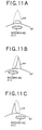
For example, FIG. 11 is an imaginary illustration showing the
relationship between recording pit positions and waveforms of an LPP
signal. FIG. 11A shows a case where a mark portion of the recording pit
is overlapped on the overall LPP in the land portion. In this case, the
amplitude level of the LPP signal component (solid-line portion) as a whole
drops compared to the LPP signal component on which no recording pit is
overlapped (broken-line portion).
FIGs. 11B and 11C show cases where the mark portion of the
recording pit is overlapped on part of the LPP in the land portion. In
these cases, the amplitude level of the LPP signal component (solid-line
portion) drops only in the portion on which the recording pit is overlapped,
compared to the LPP signal component (broken-line portion) on which no
recording pit is overlapped.
On the other hand, since the above-mentioned AGC circuit uses
average values of the above-mentioned read signal measured for a long
time (about 10 ms) to perform AGC, it cannot correct the amplitude of a
signal like the LPP signal component whose cycle is relatively short (about
100 to 500 ns). In other words, the conventional pre-pit detecting device
has the above-mentioned AGC circuit insufficient to correct the amplitude
of the LPP signal component whose amplitude level has dropped.
As a result, the conventional pre-pit detecting device cannot make
clear the difference between the amplitude level of the LPP signal
component and the amplitude level of a noise signal component remaining
after generation of the radial push-pull signal, which causes a degradation
in LPP signal extraction performance.
SUMMARY OF THE INVNETION
The present invention has been made in view of the above-mentioned
problems, and it is an object thereof to provide a pre-pit
detecting apparatus capable of correcting the amplitude of an LPP signal
component contained in an RF component in a short time, and hence
improving LPP signal extraction performance.
The above object of the present invention can be achieved by a pre-pit
detecting apparatus of the present invention for an optical recording
medium, which has information tracks with recording pits carrying record
information formed thereon and guide tracks for guiding a light beam to
the information tracks, and further has pre-pits carrying pre-information
formed on the guide tracks. The pre-pit detecting apparatus including an
amplitude correcting circuit, which when the optical beam is irradiated to
one of the information tracks, corrects the amplitude of a first read signal
and the amplitude of a second read signal generated on the basis of the
outputs of electrical signals from a light receiving unit, divided into two
parts by a division line at least optically parallel with the information track,
such that the pre-pit detecting apparatus performs a computation on the
difference between the corrected first and second read signals to generate
a difference signal so as to detect a pre-pit signal on the basis of the
difference signal. Further, said amplitude correcting circuit is provided
with: an addition signal generating device for adding the first read signal
to the second read signal to generate an addition signal; a first amplitude
correcting device for correcting the amplitude of the first read signal, on
the basis of the generated addition signal, for an RF signal component
corresponding to a recording pit, which is contained in the first read
signal; and a second amplitude correcting device for correcting the
amplitude of the second read signal, on the basis of the generated addition
signal, for an RF signal component corresponding to a recording pit, which
is contained in the second read signal.
According to the present invention, the first and second read
signals generated on the basis of the outputs of electrical signals from the
light receiving portion are input to the amplitude correcting circuit in
which the first and second read signals are added to generate the addition
signal. The amplitudes of the first and second read signals are corrected,
on the basis of the addition signal, for an RF signal component
corresponding to a recording pit, which is contained in the first and
second read signals. Then the difference between the first and second
read signals corrected is computed to generate a difference signal so that a
pre-pit signal will be detected on the basis of the difference signal.
Therefore, in the case of a recorded optical recording medium and
even when the amplitude of the pre-pit signal component drops because of
the decreased reflectivity of the pre-pit portion, the amplitude level can be
corrected in a short time. Since the amplitude of the pre-pit signal can be
corrected accurately, the difference between the amplitude level of the pre-pit
signal component and the amplitude level of a noise signal component
remaining after generation of the difference signal can be made clear,
which makes it possible to improve pre-pit signal extraction performance.
In addition, the circuit structure is simple, which can reduce
manufacturing costs and the like.
In one aspect of the present invention, said first amplitude
correcting device makes such a correction that the amplitude of the first
read signal is momentarily amplified, on the basis of the generated
addition signal, for an RF signal component corresponding to a recording
pit, which is contained in the first read signal, and said second amplitude
correcting device makes such a correction that the amplitude of the
second read signal is momentarily amplified, on the basis of the generated
addition signal, for an RF signal component corresponding to a recording
pit, which is contained in the second read signal.
According to this aspect, in the case of a recorded optical recording
medium and even when the amplitude of the pre-pit signal component
drops because of the decreased reflectivity of the pre-pit portion, since the
amplitude level can be momentarily amplified and corrected, the difference
between the amplitude level of the pre-pit signal component and the
amplitude level of a noise signal component remaining after generation of
the difference signal can be made clear, which makes it possible to
improve pre-pit signal extraction performance. In addition, the circuit
structure is simple, which can reduce manufacturing costs and the like.
In another aspect of the present invention, said amplitude
correcting circuit is further provided with an offset adjusting device that
makes the neutral points of the first and second amplitude correcting
devices coincide with each other.
According to this aspect, the pre-pit signal extraction performance
can be improved more than the above mentioned invention.
In further aspect of the present invention, said amplitude
correcting circuit is further provided with an addition-signal amplitude
fluctuation-correcting device that corrects fluctuations in amplitude of the
addition signal on the basis of whether the pit length of a recording pit
carried with the addition signal is long or short.
According to this aspect, the fluctuations in amplitude of the
addition signal can be corrected, which makes possible effective correction
of the amplitude levels of the first and second read signals.
In further aspect of the present invention, said amplitude
correcting circuit is further provided with: a first read signal delaying
device that corrects phase shift between the addition signal and the first
read signal, the phase shift produced as a result of correcting the
fluctuations in amplitude of the addition signal by said addition-signal
amplitude fluctuation-correcting device; and said second read signal
delaying device that corrects phase shift between the addition signal and
the second read signal, the phase shift produced as a result of correcting
means correcting the fluctuations in amplitude of the addition signal by
said addition-signal amplitude fluctuation-correcting device.
According to this aspect, even if phase shift is produced as a result
of correction of the fluctuations in amplitude of the addition signal, the
addition signal can be synchronized with the first read signal and the
second read signal, respectively.
In further aspect of the present invention, aid amplitude correcting
circuit is further provided with an addition-signal nonlinear amplification
device that amplifies the addition signal to make the amplification factor
for one polarity of the addition signal larger than the amplification factor
for the other polarity.
According to this aspect, the signal-to-noise ratio of the pre-pit
signal contained in the radial push-pull signal can be improved.
BRIEF DESCRIPTION OF THE DRAWINGS
FIG. 1 is a cross-sectional perspective view of a DVD-R 50
according to an embodiment of the present invention;
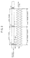
FIG. 2 is a schematic diagram showing a record format of pre-information
and rotation control information prerecorded on the DVD-R
50;
FIG. 3 is a block diagram showing the general structure of a pre-pit
detecting device 52 according to the embodiment;
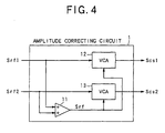
FIG. 4 is a block diagram showing an internal configuration of an
amplitude correcting circuit 1;
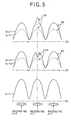
FIG. 5 shows a comparison among waveforms of first and second
read signals Srf1 and Srf2 read from the recorded DVD-R 50, waveforms
of correction signals Scs1 and Scs2 corrected by means of the amplitude
correcting circuit 1, and an addition signal Srf;
FIG. 6 is a block diagram showing an internal configuration of a
push-pull circuit 2;
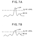
FIG. 7A is a graph showing such a state that a radial push-pull
signal Srpp is compared at a comparator in a pre-pit detecting device for
the recorded DVD-R 50 according to the present invention;
FIG. 7B is a graph showing such a state that the radial push-pull
signal Srpp is compared at a comparator in a conventional pre-pit
detecting device for the recorded DVD-R 50;
FIG. 8 is a block diagram showing a configuration of an amplitude
correcting circuit 1 according to another embodiment of the present
invention;
FIG. 9 a block diagram showing a configuration of an amplitude
correcting circuit 1 according to still another embodiment of the present
invention;
FIG. 10 is a graph showing input and output characteristics of a
nonlinear amplifier; and
FIG. 11A is an enlarged illustration of an LPP signal portion of a
signal read in a conventional pre-pit detecting signal in the case where a
mark portion of a recording pit is overlapped on an overall LPP in a land
portion;
FIG. 11B is an enlarged illustration of an LPP signal portion of a
signal read in a conventional pre-pit detecting signal in the case where a
mark portion of a recording pit is overlapped on part of an LPP in a land
portion; and
FIG. 11C is an enlarged illustration of an LPP signal portion of a
signal read in a conventional pre-pit detecting signal in the case where a
mark portion of a recording pit is overlapped on part of an LPP in a land
portion.
DESCRIPTION OF THE PREFERRED EMBODIMENTS
The following section will describe preferred embodiments of the
present invention with reference to the accompanying drawings. It
should be noted that the embodiments to be described below assume a
pre-pit detecting device for detecting pre-pits from a DVD-R as a recording
medium on which address information indicative of an information
recording position on the recording medium and reference signals for
generating clock signals for use in recording and reproducing operations
are formed as LPPs.
Referring first to FIG. 1, description will be made about the
physical structure of the DVD-R according to an embodiment of the
present invention. FIG. 1 is a cross-sectional perspective view of the
DVD-R 50 according to the embodiment of the present invention. As
shown in FIG. 1, the DVD-R 50 is a pigment type DVD-R which is
provided with a pigment film 105 capable of writing information once.
Pre-grooves 102 as information tracks on which record information is to
be recorded, and lands 103 as guide tracks for guiding a light beam B like
a laser beam as reproducing and recording light to the pre-grooves 102
are formed on the DVD-R 50. The DVD-R 50 is also provided with a
protective film for protecting the pre-grooves and the lands, and a
reflection surface 106 for reflecting the optical beam B at the time of
reproduction of record information. Then LPPs 104 are formed on the
lands 103.
In the DVD-R 50, the pre-grooves 102 are wobbled at a frequency
used as a standard of reference to the rotation speed of the DVD-R 50.
Upon recording on the DVD-R 50 record information (information such as
image information intended to be recorded other than pre-information and
sync signals), the wobbling frequency of the pre-grooves 102 is detected at
an information recording apparatus to obtain a sync signal so that the
DVD-R 50 will be controlled to rotate at a predetermined speed. At this
time, the LPPs 104 are also detected to obtain pre-information beforehand
so as to obtain address information and the like indicative of information
recording positions on the DVD-R 50. Thus the record information is
recorded at a corresponding recording position based on the address
information.
In recording the record information, the light beam B is so
irradiated that the center of the light beam B will coincide with the center
of a corresponding pre-groove 102. As a result, a recording information
pit corresponding to the record information is formed on the pre-groove
102 to form the record information. At this time, the size of the light spot
SP is so set that the light spot SP is irradiated not only to the pre-groove
102 but partially to the adjacent land 103 as well. Using reflected light of
the light spot partially irradiated to the land 103, pre-information is
detected from the LPP 104 by a push-pull method to obtain the pre-information.
On the other hand, using reflected light of the light spot
irradiated to the pre-groove 102, a wobble signal is detected from the pre-groove
102 to obtain a clock signal for rotation control.
Referring next to FIG. 2, description will be made about a record
format of the pre-information and rotation control information pre-recorded
on the DVD-R 50. It should be noted that the term "pre-recorded"
means "preformed" as a disk. FIG. 2 is a schematic diagram
showing a record format of the pre-information and rotation control
information pre-recorded on the DVD-R 50. In FIG. 2, the upper portion
shows a record format of the record information, and corrugated
waveforms of the lower portion show a wobbling state (a plan view) of the
pre-grooves 102 for recording the record information. Further, upward
arrows between the record information and the wobbling state of the pre-grooves
102 schematically show positions at which LPPs 104 are formed.
It should be noted that in FIG. 2 the wobbling state of the pre-grooves 102
is shown with amplitude greater than actual amplitude for the sake of
clarity. Further, the record information is recorded on the centerline of
each corresponding pre-groove 102.
As shown in FIG. 2, the record information to be recorded on the
DVD-R 50 is divided beforehand on a sync-frame basis. 26 sync frames
form one recording sector as an information unit, and 16 recording sectors
form one ECC block as an information block. It should be noted that one
sync frame has a length 1488 times (1488T) longer than the unit length
(hereinafter called T) corresponding to a bit interval defined by the record
format for recording the above-mentioned record information. Further,
sync information SY for synchronization on a sync-frame basis is recorded
in the top 14 T portion of each sync frame.
On the other hand, the pre-information to be recorded on the DVD-R
50 is recorded on a sync-frame basis. In recording the pre-information
using the LPPs 104, one LPP 104, as indicating a sync signal in the pre-information,
is always formed on the land 103 adjacent to a region in
which the sync information SY is recorded for each sync frame of the
record information. Meanwhile, one or two LPPs 104 indicative of the
contents of the pre-information to be recorded are formed on the land 103
adjacent to the first half of the sync frame containing information other
than the sync information SY (or no LPP 104 may be formed with respect
to the first half of the sync frame containing information other than the
sync information SY, depending on the contents of the pre-information to
be recorded). At this time, the LPPs 104 are formed in either even-numbered
frames (hereinafter called the "EVEN frames") or odd-numbered
frames (hereinafter called the "ODD frames") of each recording sector to
record the pre-information. In other words, if the LPPs 104 are formed in
the EVEN frames in FIG. 2 (as indicated with the solid upward arrows), no
LPPs 104 will be formed in the ODD frames adjacent to the EVEN frames.
The relationship between the wobbling state of the pre-grooves 102
and the LPPs 104 is accounted for by the fact that the LPPs 104 are
formed in positions where the amplitude of wobbling becomes the
maximum.
On the other hand, the pre-grooves 102 are wobbled all over the
sync frames on a constant wobbling frequency, f0 of 140 kHz (at which
one sync frame corresponds to a part for eight waves of the fluctuating
waveform of the pre-grooves 102). Then the constant wobbling frequency,
f0 is detected by a pre-pit detecting device or the like to extract a sync
signal for use in controlling the revolution of a spindle motor, not shown,
for rotating the DVD-R 50.
Referring next to FIGs. 3 through 7, description will be made about
a pre-pit detecting device for detecting pre-pits from the above-mentioned
DVD-R 50 according to the present invention. The following description
will be made by taking as an example a case where a pre-pit signal is
extracted from the recorded DVD-R 50.
FIG. 3 is a block diagram showing the general structure of a pre-pit
detecting device 52 as practiced in the embodiment. It should be noted
that the pre-pit detecting device according to the present invention is
applied to an information recording and reproducing apparatus for
recording media in an actual situation, but description of the structure
and operation of apparatus components other than the pre-pit detecting
device 52 will be omitted in the embodiment.
As shown in FIG. 3, the pre-pit detecting device 52 includes an
amplitude correcting circuit 1, a push-pull circuit 2, a signal binarizing
circuit 3 and a decoder 4. In operation, a first read signal Srf1 and a
second read signal Srf2 are input from a pickup 51 to the amplitude
correcting circuit 1 of the pre-pit detecting device 52. The first read
signal Srf1 and the second read signal Srf2 are generated as follows.
First, a light beam is irradiated from the pickup 51. Then reflected light
from the information recording surface of the DVD-R 50 driven to rotate is
received at a light receiving portion, not shown, which is divided into two
parts by a division line at least optically parallel with the tangential
direction of the pre-grooves 102 on the DVD-R 50. The light receiving
portion outputs electrical signals according to the amounts of reflected
light received at the light receiving portion, so that the first and second
read signals are generated on the basis of the electrical signals.
FIG. 4 is a block diagram showing an internal configuration of the
amplitude correcting circuit 1 as characterized by the present invention.
As shown in FIG. 4, the amplitude correcting circuit 1 includes an adder
11 as addition signal generating means, a voltage control amplifier (VCA)
12 as first amplitude correcting means, and a voltage control amplifier
(VCA) 13 as second amplitude correcting means.
The adder 11 adds the first and second read signals Srf1 and Srf2
supplied from the pickup 51 to supply the same to the voltage control
amplifiers 12, 13 as an addition signal (amplification factor-control signal)
Srf, respectively.
The voltage control amplifier 12 amplifies and corrects the
amplitude of the first read signal Srf1 momentarily (in a short time), for
each recording pit of the RF signal component contained in the first read
signal Srf1 supplied from the pickup 51, at an amplification factor based
on the addition signal Srf supplied from the adder 11. The corrected
signal is output to the push-pull circuit 2 as a correction signal Scs1 of
the first read signal Srf1.
On the other hand, the voltage control amplifier 13 momentarily
amplifies and corrects the amplitude of the second read signal Srf2, for
each recording pit of the RF signal component contained in the second
read signal Srf2 supplied from the pickup 51, at an amplification factor
based on the addition signal Srf supplied from the adder 11. The
corrected signal is output to the push-pull circuit 2 as a correction signal
Scs2 of the second read signal Srf1.
The voltage control amplifiers 12, 13 amplify the first and second
read signals Srf1 and Srf2, respectively, at an amplification factor which is
increased as the amplitude level of the addition signal Srf increases.
FIG. 5 shows a comparison among the first and second read
signals Sfr1 and Srf2 read from the recorded DVD-R 50, the correction
signals Scs1 and Scs2 corrected by means of the amplitude correcting
circuit 1, and the addition signal Srf.
As shown in FIG. 5, the amplitude of the first read signal Srf1
(broken-line portion) is momentarily amplified at timing at which the
addition signal Srf corresponding to the recording pit is input, and turned
into the correction signal Scs1 (solid-line portion). Also, the amplitude of
the LPP signal component, which is overlapped with the first read signal
Srf1 corresponding to the recording pit, is momentarily amplified.
Similarly, the amplitude of the second read signal Srf2 (broken-line
portion) is momentarily amplified at timing at which the addition signal
Srf corresponding to the recording pit is input, and turned into the
correction signal Scs2 (solid-line portion). Also, the amplitude of the LPP
signal component, which is overlapped with the second read signal Srf2
corresponding to the recording pit, is momentarily amplified.
In other words, even if the LPP 104 is overlapped with the
recording pit and hence the amplitude level of the LPP signal component
drops, the amplitude level can be momentarily amplified at a timing which
the RF signal component corresponding to the recording pit is input, at an
amplification factor based on the amplitude of the addition signal Srf
corresponding to the recording pit portion.
Further, since the addition signal Srf is a sum signal of the first
and second read signals Srf1 and Srf2, the amplification factor for the
amplitude of the first read signal Srf1 can be made equal to the
amplification factor for the amplitude of the second read signal Srf2.
Although the amplitudes of the RF signal components are also
amplified, since one signal is made opposite in polarity to the other in the
push-pull circuit 2 to be described later, the RF signal components
identical in polarity are compensated with each other at the time of
generation of the radial push-pull signal. As a result, the sum of the LPP
signal components, mutually opposite in polarity, of the first and second
read signals Srf1 and Srf2 ends up the radial push-pull signal.
Therefore, the difference between the amplitude level of the LPP
signal component and the amplitude level of a noise component remaining
after generation of the radial push-pull signal can be made clear.
FIG. 6 is a block diagram showing an internal configuration of the
push-pull circuit 2. As shown in FIG. 6, the push-pull circuit 2 includes
two AGC (Auto Gain Control) circuits 21 and 22. The AGC circuit 21 is
equipped with a voltage control amplifier 21a, an amplitude detection part
21b and a subtracter 21c, and has the function of making the amplitude
of a signal, obtained from the correction signal Scs1 from the amplitude
correcting circuit 1, coincident with a reference voltage (ref). To be more
specific, the voltage control amplifier 21a amplifies the correction signal
Scs1 at an amplification factor based on the difference between the
correction signal Scs1 generated at the subtracter 21c and the reference
voltage (ref) so that the amplitude of the correction signal Scs1 will be
made coincident with the reference voltage (ref). On the other hand, the
AGC circuit 22 is equipped with a voltage control amplifier 22a, an
amplitude detection part 22b and a subtracter 22c, and has the function
of making the amplitude of a signal, obtained from the correction signal
Scs2, coincident with the amplitude of the signal obtained from the
correction signal Scs1.
Then a subtracter 23 computes the difference between the
correction signals Scs1 and Scs2 to cancel the RF signal components,
identical in polarity, of the correction signals Scs1 and Scs2. On the
other hand, the LPP signal components mutually opposite in polarity are
amplified to generate a radial push-pull signal Srpp. The radial push-pull
signal Srpp is a composite signal generated by superimposing the LPP
signal component on the wobbling frequency component.
Then, as shown in FIG. 3, the signal binarizing circuit 3 includes
an amplifier 31, a comparator 32 and a slice level setting circuit 33.
In the signal binarizing circuit 3, an input of the radial push-pull
signal Srpp is supplied to the comparator 32 through the amplifier 31.
The comparator 32 compares the supplied radial push-pull signal Srpp
with a slice level supplied from the slice level setting circuit 33 to extract
an LPP signal to be output to the decoder 4.
The slice level setting circuit 33 receives error detection signals
detected when the decoder 4 decodes the LPP signal, and counts the
number of the error detection signals. Then, when the slice level becomes
unsatisfactory for an error rate decided for a predetermined block unit (for
example, for each ECC (Error Correction Code) block), the slice level
setting circuit 33 resets the slice level.
FIG. 7A shows as an example such a state that the radial push-pull
signal Srpp is compared at the comparator 32 in the case of the
recorded DVD-R 50. FIG. 7B shows as an example such a state that the
radial push-pull signal Srpp is compared at a comparator in a
conventional pre-pit detecting device (which has no means like the
amplitude correcting circuit 1 for correcting the amplitude level of the LPP
signal component) in the case of the recorded DVD-R 50.
As shown in FIG. 7B, when the amplitude level of the pre-pit signal
component drops because of the decreased reflectivity of the pre-pit
portion in the conventional pre-pit detecting device, the amplitude of the
LPP signal and the amplitude of a noise component are very close to each
other, which makes it difficult to set a slice level. In this case, there is a
high possibility that the noise component will be binarized to generate the
LPP signal.
On the other hand, as shown in FIG. 7A, even when the amplitude
level of the pre-pit signal component drops because of the decreased
reflectivity of the pre-pit portion in the pre-pit detecting device 52
according to the present invention, the difference between the amplitudes
of the LPP signal component and the noise component can be made clear,
which makes it easy to set the slice level, and hence generate an LPP
signal from which the noise component is removed to the utmost.
In particular, since an LPP (such as an LPP for generating address
information) other than the LPP for generating a sync signal tends to vary
its position relative to the recording pit at random, a short-time amplitude
correction according to the present invention can be more effective at
extracting the LPP such as the LPP for generating address information.
The decoder 4 decodes the LPP signal to generate address
information indicative of information recording positions and various
timing signals to be output to a system control unit, not shown, which
performs control necessary to record information on the DVD-R 50 on the
basis of the address information and the timing signals.
As discussed above and according to the embodiment, even if the
amplitude level of the pre-pit signal component drops because of
overlapping of the recording pit and the LPP 104, the amplitude level can
be momentarily amplified and corrected in the recording pit portion of the
RF signal component. As a result, the difference between the amplitude
level of the pre-pit signal component and the amplitude level of the noise
component remaining after generation of the difference signal can be made
clear, which makes it possible to improve pre-pit signal extraction
performance.
FIG. 8 is a block diagram showing an internal configuration of an
amplitude correcting circuit 1 according to another embodiment of the
present invention. The amplitude correcting circuit 110 shown in FIG. 8
includes an offset adjusting circuit 14 as offset adjusting means in
addition to the amplitude correcting circuit 1 shown in FIG. 4.
The above-mentioned voltage control amplifiers 12 and 13 may
vary in neutral point from each other. In such a case, if the voltage level
is the same, the amplification factor is difference therebetween, which may
cause an degradation in LPP signal extraction performance. To avoid this,
the amplitude correcting circuit 110 is provided with the offset adjusting
circuit 14, so that both neutral points are made to coincide, thereby
improving LPP signal extraction performance more than in the amplitude
correcting circuit 1 shown in FIG. 4.
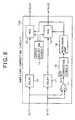
FIG. 9 is a block diagram showing an amplitude correcting circuit
1 according to still another embodiment of the present invention. The
amplitude correcting circuit 120 shown in FIG. 9 includes, in addition to
the amplitude correcting circuit 1 shown in FIG. 8, an MTF correcting
circuit 15 as addition-signal amplitude fluctuation-correcting means,
delay circuits 16, 17 as delay means, and a nonlinear amplifier 18 as
addition-signal nonlinear amplification means.
The MTF correcting circuit 15 is operative to correct amplitude
fluctuations due to variations in pit length of recording pits carried with
the addition signal Srf appearing according to the spatial frequency
characteristics of the pickup 51. The spatial frequency characteristics
are generally low-pass characteristics. In other words, the detection
ability of the pickup 51 is reduced as the spatial frequency components of
a recording pit to be read increase (as the pit length of the recording pit
becomes shorter), which makes the amplitude of the addition signal Srf
smaller. Since the length of a recording pit vary according to the
information to be recorded, long recording pits and short recording pits
(hereinafter called long pits and short pits as required) exist together in
the addition signal Srf. Thus the addition signal Srf varies according to
the recording pit length.
The MTF correcting circuit 15 is to correct fluctuations in
amplitude of the addition signal Srf resulting from variations in pit length
of the recording pits. For example, the MTF correcting circuit 15 is
constituted by a component such as an HBF (High Boost Filter) capable of
increasing the amplification factor as the signal frequency becomes higher.
In such a configuration, the amplitude correcting circuit 120 corrects a
drop in amplitude of the addition signal Srf because of the short pit so
that the amplitude level will rise to a level substantially equivalent to the
amplitude level caused by the long pit. Then the corrected amplitude
level is output to the nonlinear amplifier 22, which makes is possible to
supply an appropriate addition signal Srf to the voltage control amplifiers
12 and 13, respectively.
Correction for fluctuations in amplitude of the addition signal Srf,
however, produces phase shift between the addition signal Srf and the
first and second read signals Srf1 and Srf2. Therefore, the delay circuits
16, 17 are provided for delaying inputs of the first and second read signals
Srf1 and Srf2 for a predetermined time period. In this case, since the
time the addition signal Srf passes through the circuit is extended, the
first and second read signals Srf1 and Srf2 can be made in phase with
each other.
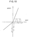
The nonlinear amplifier 18 also has input and output
characteristics exhibiting non-linearity approximating a line chart as
shown in FIG. 10. To be more specific, it has such a characteristic that
the amplification factor for positive input of an input signal becomes larger
than that for negative input of the input signal. Therefore, the signal
input to the nonlinear amplifier 18 becomes an output signal whose
positive amplitude level is emphasized, which is more effectively at
controlling the gains of the VCAs 12 and 13.
In the embodiment, the polarity of the addition signal Srf from the
MTF correcting circuit 15, which corresponds to a recording pit formed on
the DVD-R 50, is set to become positive. Therefore, the nonlinear
amplifier 18 can amplify the addition signal Srf so that the signal level
corresponding to the recording pit for the addition signal Srf becomes
larger than the signal level that does not correspond to the recording pit,
that is, the amplitude becomes greater than that of the negatively
polarized portion of the addition signal Srf.
The addition signal Srf thus output from the nonlinear amplifier 18
is output to the voltage control amplifiers 12 and 13 as the amplification
factor-control signal. Such a biased emphasis is placed because, when
the reflectivity is reduced by forming an LPP 104 on a land adjacent to the
recording pit, the signal component of the LPP 104 is contained in the
positively polarized side of the first read signal Srf1. Therefore, the
positively polarized component of each read signal need to be emphasized,
which makes it possible to improve the signal-to-noise ratio of the LPP
signal contained in the radial push-pull signal Srpp.
Thus the amplitude correcting circuit 120 shown in FIG. 9 can
obtain the effects equivalent to those of the amplitude correcting circuit
110 shown in FIG. 8. However, the amplitude correcting circuit 110
shown in FIG. 4 or 8 is enough to attain the object of the present
invention. The amplitude correcting circuit 110 is better than the
amplitude correcting circuit 120 in the manufacturing period, the
manufacturing costs, the inspection period and the like because of its
simple circuit structure.
In the above-embodiments, the DVD-R was taken by way of
example to describe the present invention, but the present invention is not
limited thereto, and it is applicable to any other recording media such as a
DVD-RW and a CD-R.
As described above and according to the present invention, even if
the amplitude level of the pre-pit signal component drops because of
overlapping of the recording pit and the LPP, the amplitude level can be
momentarily amplified and corrected in the recording pit portion of the RF
signal component. As a result, the difference between the amplitude level
of the LPP signal component and the amplitude level of the noise
component remaining after generation of the radial push-pull signal can
be made clear, which makes it possible to improve LPP signal extraction
performance.
The invention may be embodied in other specific forms without
departing from the spirit or essential characteristics thereof. The present
embodiments are therefore to be considered in all respects as illustrative
and not restrictive, the scope of the invention being indicated by the
appended claims rather than by the foregoing description and all changes
which come within the meaning and range of equivalency of the claims are
therefore intended to be embraced therein.