EP0880132A2 - Pre-pit detecting apparatus and method - Google Patents
Pre-pit detecting apparatus and method Download PDFInfo
- Publication number
- EP0880132A2 EP0880132A2 EP98109101A EP98109101A EP0880132A2 EP 0880132 A2 EP0880132 A2 EP 0880132A2 EP 98109101 A EP98109101 A EP 98109101A EP 98109101 A EP98109101 A EP 98109101A EP 0880132 A2 EP0880132 A2 EP 0880132A2
- Authority
- EP
- European Patent Office
- Prior art keywords
- signal
- information
- pit
- track
- record
- Prior art date
- Legal status (The legal status is an assumption and is not a legal conclusion. Google has not performed a legal analysis and makes no representation as to the accuracy of the status listed.)
- Withdrawn
Links
Images


Classifications
-
- G—PHYSICS
- G11—INFORMATION STORAGE
- G11B—INFORMATION STORAGE BASED ON RELATIVE MOVEMENT BETWEEN RECORD CARRIER AND TRANSDUCER
- G11B19/00—Driving, starting, stopping record carriers not specifically of filamentary or web form, or of supports therefor; Control thereof; Control of operating function ; Driving both disc and head
- G11B19/20—Driving; Starting; Stopping; Control thereof
- G11B19/24—Arrangements for providing constant relative speed between record carrier and head
- G11B19/247—Arrangements for providing constant relative speed between record carrier and head using electrical means
-
- G—PHYSICS
- G11—INFORMATION STORAGE
- G11B—INFORMATION STORAGE BASED ON RELATIVE MOVEMENT BETWEEN RECORD CARRIER AND TRANSDUCER
- G11B19/00—Driving, starting, stopping record carriers not specifically of filamentary or web form, or of supports therefor; Control thereof; Control of operating function ; Driving both disc and head
- G11B19/02—Control of operating function, e.g. switching from recording to reproducing
- G11B19/12—Control of operating function, e.g. switching from recording to reproducing by sensing distinguishing features of or on records, e.g. diameter end mark
-
- G—PHYSICS
- G11—INFORMATION STORAGE
- G11B—INFORMATION STORAGE BASED ON RELATIVE MOVEMENT BETWEEN RECORD CARRIER AND TRANSDUCER
- G11B19/00—Driving, starting, stopping record carriers not specifically of filamentary or web form, or of supports therefor; Control thereof; Control of operating function ; Driving both disc and head
- G11B19/20—Driving; Starting; Stopping; Control thereof
- G11B19/28—Speed controlling, regulating, or indicating
Definitions
- the present invention relates to an information recording apparatus for recording record information such as video information, audio information or the like to be principally recorded, by reproducing (i) address information or a synchronization signal necessary for a positional retrieval when recording the record information or (ii) rotational control information for a rotational control of the record medium such as a wobbling signal etc., (hereinafter, these are referred to as "pre-information"), onto the record medium of postscript WO (Write Once) type on which the pre-information is recorded in advance (hereafter, referred to as a DVD-R (DVD-Recordable)) among high density record media represented by the DVD whose record density is drastically improved as compared with a conventional CD (Compact Disk) and the like. More specifically, the present invention relates to a pre-pit detecting apparatus for detecting a pre-pit formed on the DVD-R or the like in such an information recording apparatus.
- CD-R CD-Recordable
- an optical disk having a record capacity similar to that of the CD, on which the pre-information is recorded beforehand and onto which the postscript information can be recorded afterward in accordance with the pre-information.
- an information track (a groove track or a land track), onto which the record information is to be recorded, is wobbled into a wave shape at a frequency corresponding to a signal into which the pre-information to be recorded is beforehand FM (Frequency Modulation)-modulated, so that the preinformation is recorded.
- FM Frequency Modulation
- a wobbling frequency of the wobbled track is detected.
- a standard clock to rotation-control the CD-R is extracted on the basis of the detection.
- a drive signal to rotation-control a spindle motor for rotating the CD-R is generated on the basis of the extracted standard clock.
- a clock signal for a recording operation including timing information synchronized with the rotation of the CD-R is generated.
- the pre-information is reproduced when recording the record information. Then, a position to be recorded is detected on the basis of the reproduced pre-information, to thereby record the record information.
- the interval between the information tracks adjacent to each other on the above described DVD-R is approximately half of that on the CD-R because of the demand for improving the record density.
- an information track (for example, a groove track) in the DVD-R is wobbled at a frequency on the basis of the standard clock, so that the rotational control information is recorded thereon.
- the pre-information is recorded by forming a pre-pit corresponding to the pre-information on a track (for example, a land track) between the two information tracks.
- the pre-pits are formed substantially uniform over the whole recording surface of the DVD-R.
- the pre-information is obtained by detecting such pre-pits, so that the rotational control and the recording control are accurately performed on the basis of the pre-information.
- the detection of the pre-pit is performed in a following manner.
- a gate signal as shown in FIG. 8 is generated, which is synchronized with a signal including a wobbling frequency component (hereinafter, referred to as a "wobbling signal”) obtained by irradiating the information track with a light beam.
- a wobbling signal a signal including a wobbling frequency component obtained by irradiating the information track with a light beam.
- the pre-pit signal which is superimposed on the wobbling signal is extracted.
- the present invention is proposed in view of the above mentioned problems. It is therefore an object of the present invention to provide an apparatus for and a method of detecting a pre-pit signal, which can accurately detect the pre-pit signal, even if a noise component is superimposed on a wobbling signal.
- a pre-pit detecting apparatus for detecting a pre-pit when recording record information onto a record medium, on which a moving control information to control a moving speed of said record medium when recording the record information onto said record medium is recorded by wobbling an information track, where the record information is to be recorded on said record medium, at a frequency corresponding to the moving control information, and on which record control information to control recording the record information onto said record medium is also recorded in advance by forming the pre-pit in a predetermined phase relation to the wobbled information track.
- the pre-pit detecting apparatus is provided with: a pickup device for simultaneously emitting a light beam onto said information track and an adjacent track, which is adjacent to said information track, and then outputting a reproduction signal based on a reflection light from said information track and said adjacent track of the emitted light beam; a wobbling signal extracting device for extracting a wobbling signal, which indicates the moving control information, out of the outputted reproduction signal; a synchronization signal generating device for generating a synchronization signal, whose phase and frequency are respectively coincident with those of the extracted wobbling signal and whose maximum amplitude position is set to a position of the pre-pit signal superimposed on the wobbling signal; a modulating device for amplitude-modulating the outputted reproduction signal with the generated synchronization signal; and a detecting device for comparing the amplitude-modulated reproduction signal with a predetermined reference signal and outputting a pre-pit detection signal.
- the light beam is simultaneously emitted by the pickup device onto the information track and the adjacent track, and the reproduction signal based on the reflection light from the information track and the adjacent track of the emitted light beam is outputted by the pickup device.
- the wobbling signal which indicates the moving control information, is extracted out of the outputted reproduction signal by the wobbling signal extracting device. This extracted wobbling signal is to be used not only for obtaining the moving control information but also for generating the synchronization signal.
- the synchronization signal whose phase and frequency are respectively coincident with those of the extracted wobbling signal and whose maximum amplitude position is set to a position of the pre-pit signal superimposed on the wobbling signal, is generated by the synchronization signal generating device.
- the outputted reproduction signal is amplitude-modulated with the generated synchronization signal by the modulating device.
- the amplitude-modulated reproduction signal is compared with the predetermined reference signal and the pre-pit detection signal is outputted by the detecting device.
- the emphasized second portion of the reproduction signal (on which the pre-pit signal is superimposed) can be surely compared with the reference signal, resulting in that the pre-pit detection signal which is accurately detected can be outputted from the pre-pit detecting apparatus of the present invention.
- the predetermined reference signal is a signal obtained by superimposing a direct current voltage having a predetermined voltage value on the extracted wobbling signal.
- the record control information includes record position information indicative of a position on the record medium where the record information is to be recorded.
- the record medium may be a DVD such as a DVD-R.
- one of the information track and the adjacent track is one of a land track and a groove track formed on the record medium, and the other of the information track and the adjacent track is the other of the land track and the groove track.
- the light beam is simultaneously emitted by the pickup device onto the groove track and the land track, and the reproduction signal based on the reflection light from the groove track and the land track of the emitted light beam is outputted by the pickup device. Therefore, even in case of the record medium on which the record control information is recorded on the land track (or the groove track), it is still possible to record the record information onto the groove track (or the land track) while accurately detecting the pre-pit detection signal.
- the above object of the present invention can be also achieved by a pre-pit detecting method of detecting a pre-pit when recording record information onto a record medium, on which a moving control information to control a moving speed of said record medium when recording the record information onto said record medium is recorded by wobbling an information track, where the record information is to be recorded on said record medium, at a frequency corresponding to the moving control information, and on which record control information to control recording the record information onto said record medium is also recorded in advance by forming the pre-pit in a predetermined phase relation to the wobbled information track.
- the pre-pit detecting method has: a pickup process of simultaneously emitting a light beam onto said information track add an adjacent track, which is adjacent to said information track, and then outputting a reproduction signal based on a reflection light from said information track and said adjacent track of the emitted light beam; a wobbling signal extracting process of extracting a wobbling signal, which indicates the moving control information, out of the outputted reproduction signal; a synchronization signal generating process of generating a synchronization signal, whose phase and frequency are respectively coincident with those of the extracted wobbling signal and whose maximum amplitude position is set to a position of the pre-pit signal superimposed on the wobbling signal; a modulating process of amplitude-modulating the outputted reproduction signal with the generated synchronization signal; and a detecting process of comparing the amplitude-modulated reproduction signal with a predetermined reference signal and outputting a pre-pit detection signal.
- the light beam is simultaneously emitted in the pickup process onto the information track and the adjacent track, and the reproduction signal based on the reflection light from the information track and the adjacent track of the emitted light beam is outputted in the pickup process.
- the wobbling signal is extracted out of the outputted reproduction signal in the wobbling signal extracting process.
- the synchronization signal is generated in the synchronization signal generating process.
- the outputted reproduction signal is amplitude-modulated with the generated synchronization signal in the modulating process.
- the amplitude-modulated reproduction signal is compared with the predetermined reference signal and the pre-pit detection signal is outputted in the detecting process.
- the predetermined reference signal is a signal obtained by superimposing a direct current voltage having a predetermined voltage value on the extracted wobbling signal.
- the record control information includes record position information indicative of a position on the record medium where the record information is to be recorded.
- the record medium may be a DVD such as a DVD-R.
- one of the information track and the adjacent track is one of a land track and a groove track formed on the record medium, and the other of the information track and the adjacent track is the other of the land track and the groove track.
- a DVD-R as one example of a record medium for use in the embodiment, on which a pre-pit is formed in correspondence with pre-information as record control information and on which rotational control information is also recorded by wobbling a groove track described later at a predetermined frequency is explained with reference to FIGs. 1 and 2.
- a DVD-R 1 is a pigment type of DVD-R which has a pigment film 5 and onto which information can be written only once.
- the DVD-R 1 there is formed a groove track 2 servicing as an information track and a land track 3 servicing as an adjacent track to guide to the groove track 2 a light beam B, such as a laser beam or the like as a reproducing light or a recording light.
- the DVD-R 1 has: a protection film 7 to protect the groove track 2 and the land track 3; and a metallic deposition surface 6 to reflect the light beam B when reproducing the recorded information.
- a pre-pit 4 corresponding to pre-information is formed on the land track 3. This pre-pit 4 is beforehand formed before a shipment of the DVD-R 1.
- the groove track 2 is wobbled at a frequency corresponding to a rotational speed of the DVD-R 1.
- the recording operation of the rotational control information by wobbling the groove track 2 is beforehand executed before the shipment of the DVD-R 1, similarly to the pre-pit 4.
- the record information (hereafter, this implies the information, such as video information, audio information and the like to be principally recorded other than the pre-information and the rotational control information) onto the DVD-R 1
- a frequency in wobbling of the groove track 2 is detected by an information recording apparatus described later, to thereby obtain the rotational control information and the DVD-R 1 is rotation-controlled at a predetermined rotational speed.
- the pre-pit 4 is detected to beforehand obtain the pre-information to thereby set an optimum output of the light beam B servicing as the recording or reproducing light in accordance with the obtained pre-information.
- the address information indicative of the position on the DVD-R 1 onto which the record information is to be recorded is obtained. The record information is then recorded onto the corresponding record position on the basis of this obtained address information.
- the light beam B is emitted such that a center thereof coincides with the center of the groove track 2. Then, a record information pit corresponding to the record information is formed on the groove track 2 to thereby record the record information.
- a size of a light spot SP is set such that one portion of the light spot SP is emitted not only onto the groove track 2 but also onto the land track 3, as shown in FIG. 1.
- the pre-information is detected from the pre-pit 4 by a push-pull method (a push-pull method using a light detector divided by a division line parallel to a rotational direction of the DVD-R 1 (hereafter, referred to as "a radial push-pull method”)) using some of the reflection light from the light spot SP on the land track 3 to thereby obtain the pre-information.
- a push-pull method a push-pull method using a light detector divided by a division line parallel to a rotational direction of the DVD-R 1 (hereafter, referred to as "a radial push-pull method”
- the wobbling signal is detected from the groove track 2 by using the reflection light from the light spot SP on the groove track 2 to thereby obtain a clock signal for the rotation control.
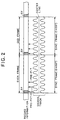
- FIG. 2 an upper block shows the record format for the record information
- each of wave forms in wave shapes at a lower block shows a wobbling state at the groove track 2 on which the record information is to be recorded (i. e., corresponding to a plan view of the groove track 2)
- upward arrows between the wobbling state of the groove track 2 and the record information schematically show positions on which the pre-pits 4 are formed respectively.
- the wobbling state of the groove track 2 is indicated by using an amplitude higher than an actual amplitude for the purpose of an easy understanding.
- the record information is recorded on a central line of the groove track 2.
- the record information recorded on the DVD-R 1 in the embodiment is divided in advance for each synchronization frame as an information unit. And that, one recording sector is composed of 26 synchronization frames. Moreover, one ECC (Error Correcting Code) block is composed of 16 recording sectors.
- One synchronization frame has a length equal to 1488 times (1488T) of the unit length (hereafter, referred to as T) corresponding to a pit interval prescribed by the record format when recording the record information.
- a synchronization information SY to achieve a synchronization for each synchronization frame is recorded on a portion having a length of 14T at the leading head of one synchronization frame.
- the pre-information recorded on the DVD-R 1 in the embodiment is recorded for each synchronization frame.
- one pre-pit 4 to indicate a synchronization signal in the pre-information is formed on a land track 3 adjacent to an area on which the synchronization information SY in each synchronization frame in the record information is recorded.
- two or one pre-pit 4 to indicate a content of the pre-information to be recorded is formed on a land track 3 adjacent to a former portion within the synchronization frame other than the synchronization information SY (incidentally, as for the former portion within the synchronization frame other than the synchronization information SY, there may be a case that the pre-pit 4 is not formed depending upon the content of the pre-information to be recorded).
- the pre-pit 4 is formed only on the synchronization frames having an even number (hereafter, referred to "an EVEN frame”) or only on the synchronization frames having an odd number (hereafter, referred to as "an ODD frames”), so that the pre-information is recorded. Namely, in FIG. 2, if the pre-pit 4 is formed on the EVEN frame (shown by upward solid arrows in FIG. 2), the pre-pits 4 are not formed on the ODD frames adjacent to the EVEN frame.
- the groove track 2 is wobbled at a constant wobbling frequency f 0 of 140 kHz (i. e., a frequency at which one synchronization frame corresponds to 8 waves) over all the synchronization frames. Then, a signal for the rotational control of the spindle motor is detected by detecting the constant wobbling frequency f 0 , in the information recording apparatus described later.
- the pre-pit 4 containing the address information on the DVD-R 1 and the groove track 2 which wobbles are formed beforehand on the DVD-R 1.
- the pre-pit 4 is detected at first to thereby obtain the address information on the DVD-R 1, and then the record position is detected, at which the digital information i. e., the record information is recorded onto the DVD-R 1.
- an information recording apparatus S as the embodiment is provided with: a pickup 10 servicing as one example of a pickup device and a recording device; a reproduction amplifier 11; a decoder 12; a pre-pit signal decoder 13; a spindle motor 14 servicing as one example of a rotating device; a servo circuit 15 servicing as one example of a synchronization signal generating device; a processor (CPU) 16; an encoder 17; a power control circuit 18; a laser drive circuit 19; an interface 20; and a wobbling signal extractor 22 servicing as one example of an information extracting device.
- a digital information Srr to be recorded from an external host computer 21 is inputted through the interface 20 to the information recording apparatus S.
- the pickup 10 is provided with a laser diode, a polarization beam splitter, an objective lens, a light detector and so on which are not shown, and emits the light beam B to the information record surface of the DVD-R 1 on the basis of a laser drive signal Sdl.
- the pickup 10 On the basis of a reflection light of the light beam B, the pickup 10 detects the wobbling frequency of the groove track 2 and the pre-pit 4 by using the radial push-pull method, and thereby records the digital information Srr to be recorded. Further, if the digital information is already recorded, the pickup 10 detects the already recorded digital information on the basis of the reflection light of the light beam B.
- the reproduction amplifier 11 amplifies a detection signal Sdt including the information corresponding to the wobbling frequency of the groove track 2 and the pre-pit 4 outputted by the pickup 10, and then outputs a pre-information signal Spp corresponding to the wobbling frequency of the groove track 2 and the pre-pit 4. Further, if the digital information is already recorded, the reproduction amplifier 11 outputs an amplification signal Sp corresponding to the already recorded digital information.
- the decoder 12 applies an 8-16 demodulation and a de-interleave operation to the amplification signal Sp so as to decode the amplification signal Sp, and thereby outputs a demodulation signal Sdm and a servo demodulation signal Ssd.
- the pre-information signal Spp is inputted to the pre-pit decoder 13 and the wobbling signal extractor 22.
- the pre-pit signal decoder 13 extracts only a signal obtained by detecting the pre-pit 4 contained in the pre-information signal Spp, then outputs it as a pre-pit detection signal Spdt to the servo circuit 15, and decodes it to thereby output a corresponding demodulation pre-pit signal Spd to the processor 16.
- the wobbling signal extractor 22 extracts only the wobbling frequency of the groove track 2 included in the pre-information signal Spp to thereby output the extraction signal Sdtt to the servo circuit 15.
- the servo circuit 15 outputs a pickup servo signal Ssp for a focus servo control and a tracking servo control in the pickup 10, on the basis of the pre-pit detection signal Spdt and the servo demodulation signal Ssd. Moreover, on the basis of an extraction signal Sdtt described later, the servo circuit 15 uses the information corresponding to the wobbling frequency f 0 included in the extraction signal Sdtt and then outputs a spindle servo control signal Sss to thereby servo-control the rotation of the spindle motor 14.
- the interface 20 performs, under a control of the processor 16, an interface operation for the digital information Srr sent from the host computer 21 i. e., taking this into the information recording apparatus S to thereby output the digital information Srr to the encoder 17.
- the encoder 17 is provided with an ECC generator, an 8-16 modulator, a scrambler and the like which are not shown, and constitutes the ECC block which is a unit to perform an error correction when reproducing, on the basis of the digital information Srr, and further applies the interleave, 8-16 modulation and scramble processes to the ECC block to thereby generate a modulation signal Sre.
- the power control circuit 18 outputs a record signal Sd of controlling an output of a laser diode (not shown) within the pickup 10.
- the laser drive circuit 19 outputs the laser drive signal Sdl of actually driving the laser diode so that the laser diode in the pickup 10 emits the light beam B.
- the processor 16 uses the inputted demodulation pre-pit signal Spd and then obtains the pre-information to thereby control the operation of recording the digital information Srr at the position on the DVD-R 1 corresponding to the address information included in the pre-information.
- the processor 16 outputs a reproduction signal Sot corresponding to the digital information, which has been already recorded, to the external on the basis of the demodulation signal Sdm and mainly controls the information recording apparatus S as a whole.
- the information recording apparatus S can also reproduce the information recorded on the DVD-R 1. At that time, the reproduction signal Sot is outputted to the external through the processor 16 on the basis of the modulation signal Sdm.
- FIG. 4 is a block diagram of the pre-pit signal decoder 13.
- the BPF 27, the wobbling signal extractor 22 and the servo circuit 15 are also illustrated in order to explain input signals to the pre-pit signal decoder 13.
- the pre-pit signal decoder 13 is provided with: a threshold setting portion 23, a multiplier 24 as one example of a modulating device, a comparator 25 as one example of a detecting device and a decoder 26.
- the pre-information signal Spp inputted to the BPF 27 is, as shown in a graph (A) of FIG. 6, a signal including a high frequency noise component. Since this noise component is not removed after the signal passes through the BPF 27, the pre-information signal Spp is inputted to the pre-pit signal decoder 13 and the wobbling signal extractor 22 in a condition including this noise component.
- the wobbling signal extractor 22 is provided with a limiter, a BPF, a binary converter and so on, removes a noise component and a pre-pit signal component out of the pre-information signal Spp, and outputs the extraction signal Sdt, which is obtained by extracting only the wobbling frequency component as shown in a graph (B) of FIG. 6, to the servo circuit 15.
- the servo circuit 15 is provided with a VCO (Voltage Controlled Oscillator) 27, a frequency divider 28, a multiplier 29, an amplifier 30, an LPF (Low Pass Filter) 31 and a BPF 32 so as to constitute a PLL (Phase Locked Loop) circuit and thereby output a PLL signal Spl synchronized with the extracted wobbling signal Sdtt.
- This PLL signal Spl is, as shown in a graph (C) of FIG. 6, a signal having a phase and a frequency equal to those of the extracted wobbling signal Sdtt, and the position of the maximum amplitude thereof is coincident with the position of the pre-pit signal superimposed on the wobbling signal Sdtt.
- the pre-pit 4 is, as mentioned above, positioned at a constant phase position with respect to the groove track 2, the position where the pre-pit 4 is superimposed on the wobbling signal Sdtt is also constant.
- the pre-information signal Spp includes, as shown in a graph (A) of FIG. 6, the high frequency component, which is the noise at the time of detection, other than the frequency component corresponding to the wobbling frequency of the groove track 2, the level difference between the signal portion corresponding to the pre-pit and the other signal portion becomes small.
- the method using the gate signal as described above it is difficult to accurately detect the pre-pit signal.
- the present embodiment is intended to increase this level difference between the signal portion corresponding to the pre-pit and the other signal portion, by amplitude-modulating the pre-information signal Spp with the PLL signal Spl, so as to enable a high accurate detection of the pre-pit.
- the PLL signal Spl as a synchronization signal used for the amplitude modulation in the present embodiment has the phase equal to that of the pre-information signal Spp, and the maximum amplitude position thereof is set to a position where the pre-pit is superimposed.
- the maximum output value of the PLL signal Spl is set to a unit voltage value of the voltage representing the output of the pre-information signal Spp e. g. 1 [V].
- the minimum output value of the PLL signal Spl is set to a positive value so as not to change the polarity of the pre-information signal Spp.
- the pre-information signal Spp is amplitude-modulated. Namely, out of the pre-information signal Spp shown in a graph (A) of FIG. 7, the portion which is multiplied with the signal portion other than the maximum amplitude position of the PLL signal Spl as shown in FIG. (B), is amplitude-modulated such that the amplitude thereof is decreased as shown in a graph (C) of FIG. 7, while the amplitude of the pre-pit signal component corresponding to the maximum amplitude position of the PLL signal Spl is not changed. Therefore, by such a modulation technique, it is possible to emphasize only the component of the pre-pit signal, so that it is possible to reduce the above explained influence of the noise.
- a reference wobbling signal Sref which is biased with a voltage V1 by the threshold setting portion 23 as shown in FIG. 4, is used as a threshold signal to extract the pre-pit signal component out of the pre-information signal Smlt after the modulation as described above (but the wobbling signal is not simply used as the threshold signal).
- the output of the wobbling signal itself fluctuates due to the crosstalk from the adjacent groove track 2 as indicated by a dotted line in each of the graphs (B) and (D) of FIG. 6, so that it is difficult to accurately detect the pre-pit signal.
- the present embodiment by comparing the pre-information signal Smlt modulated with the PLL signal Spl, whose phase is equal to that of the wobbling signal Sdtt and whose maximum amplitude position is set to the pre-pit position, it is possible to accurately detect the pre-pit signal while removing the fluctuation components due to the noise component included in the pre-information signal and the crosstalk of the wobbling signal.
- the position where the pre-pit signal is superimposed on the wobbling signal is coincident with the maximum amplitude position of the wobbling signal.
- the present invention is not limited to this. Namely, the present invention can be applied to a case where the pre-pit signal is superimposed on a position other than the maximum amplitude position.
- the maximum amplitude position of the synchronization signal may be set to the superimposed position of the pre-pit signal. More concretely, the phase of the synchronization signal may be shifted on the basis of the phase position of the pre-pit with respect to the wobbling frequency, which is set beforehand.
- the present invention is applied to the DVD-R is explained in the above mentioned respective embodiments. However, it is not limited thereto. For example, it can be widely applied to a case in which determined digital information is recorded onto a record medium (for example, a record medium in a form of a tape and the like) on which the information for a record control through a wobbling operation to a track is recorded.
- a record medium for example, a record medium in a form of a tape and the like
Abstract
Description
Claims (10)
- A pre-pit detecting apparatus (S) for detecting a pre-pit (4) when recording record information onto a record medium (1), on which a moving control information to control a moving speed of said record medium when recording the record information onto said record medium is recorded by wobbling an information track (2, 3), where the record information is to be recorded on said record medium, at a frequency corresponding to the moving control information, and on which record control information to control recording the record information onto said record medium is also recorded in advance by forming the pre-pit in a predetermined phase relation to the wobbled information track, characterized in that said pre-pit detecting apparatus comprises:a pickup device (10) for simultaneously emitting a light beam (B) onto said information track and an adjacent track, which is adjacent to said information track, and then outputting a reproduction signal based on a reflection light from said information track and said adjacent track of the emitted light beam;a wobbling signal extracting device (22) for extracting a wobbling signal, which indicates the moving control information, out of the outputted reproduction signal;a synchronization signal generating device (15) for generating a synchronization signal, whose phase and frequency are respectively coincident with those of the extracted wobbling signal and whose maximum amplitude position is set to a position of the pre-pit signal superimposed on the wobbling signal;a modulating device (24) for amplitude-modulating the outputted reproduction signal with the generated synchronization signal; anda detecting device (25, 26) for comparing the amplitude-modulated reproduction signal with a predetermined reference signal and outputting a pre-pit detection signal.
- A pre-pit detecting apparatus (S) according to claim 1, characterized in that the predetermined reference signal comprises a signal obtained by superimposing a direct current voltage having a predetermined voltage value on the extracted wobbling signal.
- A pre-pit detecting apparatus (S) according to claim 1 or 2, characterized in that the record control information includes record position information indicative of a position on said record medium (1) where the record information is to be recorded.
- A pre-pit detecting apparatus (S) according to any one of claims 1 to 3, characterized in that said record medium (1) comprises a DVD.
- A pre-pit detecting apparatus (S) according to any one of claims 1 to 4, characterized in that one of said information track and said adjacent track comprises one of a land track (3) and a groove track (2) formed on said record medium (1), and the other of said information track and said adjacent track comprises the other of said land track and said groove track.
- A pre-pit detecting method of detecting a pre-pit (4) when recording record information onto a record medium (1), on which a moving control information to control a moving speed of said record medium when recording the record information onto said record medium is recorded by wobbling an information track (2, 3), where the record information is to be recorded on said record medium, at a frequency corresponding to the moving control information, and on which record control information to control recording the record information onto said record medium is also recorded in advance by forming the pre-pit in a predetermined phase relation to the wobbled information track, characterized in that said pre-pit detecting method comprises:a pickup process of simultaneously emitting a light beam (B) onto said information track and an adjacent track, which is adjacent to said information track, and then outputting a reproduction signal based on a reflection light from said information track and said adjacent track of the emitted light beam;a wobbling signal extracting process of extracting a wobbling signal, which indicates the moving control information, out of the outputted reproduction signal;a synchronization signal generating process of generating a synchronization signal, whose phase and frequency are respectively coincident with those of the extracted wobbling signal and whose maximum amplitude position is set to a position of the pre-pit signal superimposed on the wobbling signal;a modulating process of amplitude-modulating the outputted reproduction signal with the generated synchronization signal; anda detecting process of comparing the amplitude-modulated reproduction signal with a predetermined reference signal and outputting a pre-pit detection signal.
- A pre-pit detecting method according to claim 6, characterized in that the predetermined reference signal comprises a signal obtained by superimposing a direct current voltage having a predetermined voltage value on the extracted wobbling signal.
- A pre-pit detecting method according to claim 6 or 7, characterized in that the record control information includes record position information indicative of a position on said record medium (1) where the record information is to be recorded.
- A pre-pit detecting method according to any one of claims 6 to 8, characterized in that said record medium (1) comprises a DVD.
- A pre-pit detecting method according to any one of claims 6 to 9, characterized in that one of said information track and said adjacent track comprises one of a land track (3) and a groove track (2) formed on said record medium (1), and the other of said information track and said adjacent track comprises the other of said land track and said groove track.
Applications Claiming Priority (3)
| Application Number | Priority Date | Filing Date | Title |
|---|---|---|---|
| JP9130061A JPH10320781A (en) | 1997-05-20 | 1997-05-20 | Prepit signal detector and detection |
| JP130061/97 | 1997-05-20 | ||
| JP13006197 | 1997-05-20 |
Publications (2)
| Publication Number | Publication Date |
|---|---|
| EP0880132A2 true EP0880132A2 (en) | 1998-11-25 |
| EP0880132A3 EP0880132A3 (en) | 1999-10-20 |
Family
ID=15025091
Family Applications (1)
| Application Number | Title | Priority Date | Filing Date |
|---|---|---|---|
| EP98109101A Withdrawn EP0880132A3 (en) | 1997-05-20 | 1998-05-19 | Pre-pit detecting apparatus and method |
Country Status (2)
| Country | Link |
|---|---|
| EP (1) | EP0880132A3 (en) |
| JP (1) | JPH10320781A (en) |
Cited By (6)
| Publication number | Priority date | Publication date | Assignee | Title |
|---|---|---|---|---|
| WO2001001404A1 (en) * | 1999-06-29 | 2001-01-04 | Koninklijke Philips Electronics N.V. | Optical record carrier |
| EP1093123A1 (en) * | 1999-10-15 | 2001-04-18 | Pioneer Corporation | Information record disc and information recording apparatus |
| EP1184850A2 (en) * | 2000-08-07 | 2002-03-06 | Victor Company Of Japan, Ltd. | Recording and/or reproducing apparatus and recording and/or reproducing method capable of detecting a land pre-pit on disc securely at a high precision |
| EP1229533A2 (en) * | 2001-02-06 | 2002-08-07 | Pioneer Corporation | Pre-pit detecting apparatus for optical recording medium |
| US6891782B1 (en) | 1999-11-05 | 2005-05-10 | Yamaha Corporation | Optical disk recording apparatus having push-pull signal processing circuit, wobble extraction circuit and pre-pit detection circuit |
| CN1312693C (en) * | 2001-09-17 | 2007-04-25 | 蒂雅克株式会社 | Signal Process circuit |
Families Citing this family (3)
| Publication number | Priority date | Publication date | Assignee | Title |
|---|---|---|---|---|
| JP3881835B2 (en) | 2000-10-20 | 2007-02-14 | 日本ビクター株式会社 | Recording / playback device |
| JP2003203341A (en) | 2001-11-02 | 2003-07-18 | Victor Co Of Japan Ltd | Optical disk, optical disk recording and playing back device, and optical disk recording and playing back method |
| KR100643698B1 (en) | 2005-08-22 | 2006-11-10 | 삼성전자주식회사 | Device for detecting land pre-pit |
Citations (5)
| Publication number | Priority date | Publication date | Assignee | Title |
|---|---|---|---|---|
| EP0344994A2 (en) * | 1988-05-30 | 1989-12-06 | Sony Corporation | Optical disc drives |
| EP0628952A2 (en) * | 1993-06-08 | 1994-12-14 | Matsushita Electric Industrial Co., Ltd. | Optical disk, and information recording/reproduction apparatus |
| EP0714092A1 (en) * | 1994-11-22 | 1996-05-29 | Sony Corporation | Information recording and reproducing apparatus |
| EP0821350A2 (en) * | 1996-07-26 | 1998-01-28 | Hitachi, Ltd. | Information recording medium and method and apparatus for recording and reproducing information using the same |
| EP0872838A2 (en) * | 1997-04-14 | 1998-10-21 | Mitsubishi Denki Kabushiki Kaisha | Disk-rotation control apparatus |
-
1997
- 1997-05-20 JP JP9130061A patent/JPH10320781A/en active Pending
-
1998
- 1998-05-19 EP EP98109101A patent/EP0880132A3/en not_active Withdrawn
Patent Citations (5)
| Publication number | Priority date | Publication date | Assignee | Title |
|---|---|---|---|---|
| EP0344994A2 (en) * | 1988-05-30 | 1989-12-06 | Sony Corporation | Optical disc drives |
| EP0628952A2 (en) * | 1993-06-08 | 1994-12-14 | Matsushita Electric Industrial Co., Ltd. | Optical disk, and information recording/reproduction apparatus |
| EP0714092A1 (en) * | 1994-11-22 | 1996-05-29 | Sony Corporation | Information recording and reproducing apparatus |
| EP0821350A2 (en) * | 1996-07-26 | 1998-01-28 | Hitachi, Ltd. | Information recording medium and method and apparatus for recording and reproducing information using the same |
| EP0872838A2 (en) * | 1997-04-14 | 1998-10-21 | Mitsubishi Denki Kabushiki Kaisha | Disk-rotation control apparatus |
Cited By (10)
| Publication number | Priority date | Publication date | Assignee | Title |
|---|---|---|---|---|
| WO2001001404A1 (en) * | 1999-06-29 | 2001-01-04 | Koninklijke Philips Electronics N.V. | Optical record carrier |
| KR100739502B1 (en) * | 1999-06-29 | 2007-07-13 | 코닌클리케 필립스 일렉트로닉스 엔.브이. | Optical record carrier, apparatus and method for scanning such a record carrier |
| EP1093123A1 (en) * | 1999-10-15 | 2001-04-18 | Pioneer Corporation | Information record disc and information recording apparatus |
| US6891782B1 (en) | 1999-11-05 | 2005-05-10 | Yamaha Corporation | Optical disk recording apparatus having push-pull signal processing circuit, wobble extraction circuit and pre-pit detection circuit |
| EP1184850A2 (en) * | 2000-08-07 | 2002-03-06 | Victor Company Of Japan, Ltd. | Recording and/or reproducing apparatus and recording and/or reproducing method capable of detecting a land pre-pit on disc securely at a high precision |
| EP1184850A3 (en) * | 2000-08-07 | 2004-07-21 | Victor Company Of Japan, Ltd. | Recording and/or reproducing apparatus and recording and/or reproducing method capable of detecting a land pre-pit on disc securely at a high precision |
| EP1229533A2 (en) * | 2001-02-06 | 2002-08-07 | Pioneer Corporation | Pre-pit detecting apparatus for optical recording medium |
| EP1229533A3 (en) * | 2001-02-06 | 2003-09-17 | Pioneer Corporation | Pre-pit detecting apparatus for optical recording medium |
| US6928041B2 (en) | 2001-02-06 | 2005-08-09 | Pioneer Corporation | Pre-pit detecting apparatus for optical recording medium |
| CN1312693C (en) * | 2001-09-17 | 2007-04-25 | 蒂雅克株式会社 | Signal Process circuit |
Also Published As
| Publication number | Publication date |
|---|---|
| JPH10320781A (en) | 1998-12-04 |
| EP0880132A3 (en) | 1999-10-20 |
Similar Documents
| Publication | Publication Date | Title |
|---|---|---|
| JP3555055B2 (en) | Prepit detection device and information recording device | |
| US6603726B1 (en) | Pre-pit detection unit | |
| US6188655B1 (en) | Information recording apparatus | |
| US6556523B1 (en) | Wobble-signal detecting device and information recording apparatus | |
| JP3819159B2 (en) | Pre-pit signal generation device and information recording device | |
| EP0880132A2 (en) | Pre-pit detecting apparatus and method | |
| US6639882B2 (en) | Pre-pit detecting apparatus | |
| JP3881835B2 (en) | Recording / playback device | |
| JP3714117B2 (en) | Pre-pit detection device, pre-pit detection method, position and frequency signal detection circuit | |
| EP1225571B1 (en) | Pre-pit detecting apparatus | |
| US6956800B2 (en) | Pre-pit detecting apparatus detecting pre-pit signal from only signals input during period of applying light beam having reproducing power | |
| US7366067B2 (en) | Recording clock signal generating apparatus and recording clock signal generating method for information recording device | |
| JP2002074675A (en) | Prepit signal detecor and detecting method | |
| JP3876601B2 (en) | Land pre-pit detection device and optical disk device using the same | |
| CN1206904A (en) | Pre concave groove testing device and method | |
| US8064310B2 (en) | Optical disk recording device which detects pre-pit distribution and shifts recording position accordingly | |
| JP2009170005A (en) | Device and method for generating clock | |
| JP2004319089A (en) | Prepit detection device and prepit detection method | |
| JP2001052352A (en) | Optical information recording and reproducing device and method | |
| JP2001014788A (en) | Information recorder | |
| JP2004303415A (en) | Recording and/or reproducing device | |
| JP2000003555A (en) | Optical disk device | |
| JP2004030911A (en) | Optical recording medium | |
| JP2004145922A (en) | Optical disk device, and prepit signal detection method for optical disk device |
Legal Events
| Date | Code | Title | Description |
|---|---|---|---|
| PUAI | Public reference made under article 153(3) epc to a published international application that has entered the european phase |
Free format text: ORIGINAL CODE: 0009012 |
|
| AK | Designated contracting states |
Kind code of ref document: A2 Designated state(s): AT BE CH CY DE DK ES FI FR GB GR IE IT LI LU MC NL PT SE |
|
| AX | Request for extension of the european patent |
Free format text: AL;LT;LV;MK;RO;SI |
|
| PUAL | Search report despatched |
Free format text: ORIGINAL CODE: 0009013 |
|
| AK | Designated contracting states |
Kind code of ref document: A3 Designated state(s): AT BE CH CY DE DK ES FI FR GB GR IE IT LI LU MC NL PT SE |
|
| AX | Request for extension of the european patent |
Free format text: AL;LT;LV;MK;RO;SI |
|
| RIC1 | Information provided on ipc code assigned before grant |
Free format text: 6G 11B 19/12 A, 6G 11B 19/247 B, 6G 11B 19/28 B, 6G 11B 7/007 B |
|
| AKX | Designation fees paid | ||
| REG | Reference to a national code |
Ref country code: DE Ref legal event code: 8566 |
|
| STAA | Information on the status of an ep patent application or granted ep patent |
Free format text: STATUS: THE APPLICATION IS DEEMED TO BE WITHDRAWN |
|
| 18D | Application deemed to be withdrawn |
Effective date: 20000421 |