This application is based on Japanese Patent
Application Nos. 2001-014031 filed on January 23, 2001,
2001-035126 filed on February 13, 2001, and 2001-044758 filed
on February 21, 2001, the contents of which are incorporated
hereinto by reference.
BACKGROUND OF THE INVENTION
Field of the Invention
The present invention relates in general to a method
of obtaining particulars or characteristics of an ophthalmic lens
by detecting a fluorescent light which is emitted from the
ophthalmic lens upon exposure to an excitation light (UV light).
The particulars or characteristics of the ophthalmic lens include,
for instance, identifying marks such as characters, figures,
symbols, etc. which are formed in the ophthalmic lens to identify
the ophthalmic lens, a thickness of the ophthalmic lens such as a
contact lens and an intraocular lens, and an angular position of
the ophthalmic lens, particularly of a special contact lens having
circumferential portions having respective different thickness
values.
Discussion of Related Art
As one example of the particulars or characteristics
of an ophthalmic lens which give information on the lens, there
are known identifying marks formed in predetermined portions
of the ophthalmic lens such as a contact lens or an intraocular
lens. The identifying marks include characters, figures, symbols
and others, which permit or facilitate a differentiation between
front and back surfaces of the lens or between lenses for left and
right eyes. Further, the identifying marks are formed to
indicate the thickest circumferential portion in the lens or
specifications of the lens and manufacturing information such as
a manufacturer's name. For marking the ophthalmic lens, a
laser radiation is used to engrave the identifying marks in the
lens surface, or a printing liquid containing a pigment or a dye is
used.
The identifying marks formed in the ophthalmic
lens as described above are checked or read upon packaging or
shipment of the lens by a worker, for assuring delivery of a lens
suitable to a specific user, or distinguishing various types of
lenses from each other in the production line. In general, the
identifying marks are manually checked by the worker for each
of a plurality of ophthalmic lenses, by visually inspecting each
lens directly or through a magnifying glass. Since the
identifying marks are formed generally at a peripheral portion of
the lens for the purpose of avoiding an adverse influence on its
optical region, it is rather difficult to recognize the identifying
marks by the worker's visual inspection. Accordingly, the
conventional method of reading the identifying marks by the
worker's visual inspection undesirably suffers from reading
errors of the identifying marks due to sensory errors and fatigue
of individual workers. Further, the production efficiency of the
lens is undesirably deteriorated.
In view of a current trend that disposable contact
lenses are widely used, there is a demand for mass-production of
the ophthalmic lens with high production efficiency at a reduced
cost. The above-described conventional method of manually
reading the identifying marks by the worker's visual inspection,
however, does not meet the demand.
As one technique for solving the problem described
above, it is proposed to take an image of the marked ophthalmic
lens by a CCD camera, for instance, and to process the obtained
image by an image data processing device. In this technique,
however, it is difficult to obtain a sufficiently clear image of the
lens for reading the identifying marks since the ophthalmic lens
is transparent and the identifying marks formed in the lens are
transparent or pale in color.
US Patent No. 6,124,594 discloses a method of
confirming the presence of a contact lens in a package by using
an infrared radiation. JP-A-2000-177720, JP-A-11-503232, and
JP-A- 9-504095 disclose a method of detecting the presence of a
contact lens in a container, or a method of detecting defects of a
contact lens such as scratches and chips, comprising the steps of
applying an excitation light such as a UV light to the contact lens,
and taking a fluorescent image of the lens while the lens is
emitting a fluorescent light by exposure to the excitation light.
None of the methods, however, disclose or suggest reading the
identifying mark formed in the lens by utilizing the fluorescent
image. Accordingly, the identifying mark needs to be read
manually by the worker's visual inspection, thereby causing a
risk of delivering, to a user, improper lenses having the
specifications such as the optical power and the radius of
curvature, which are different from those suitable to a specific
lens user.
It is therefore a first object of the present invention
to provide a method of accurately and easily reading an
identifying mark formed in an ophthalmic lens so as to obtain
information on the lens, so that the obtained information are
compared with prepared reference information for the purpose of
distinguishing various types of lenses from each other in the
production line.
Another example of the particulars which give
information on the ophthalmic lens, the thickness of the
ophthalmic lens, especially at its optical center, is measured.
For providing a lens user with an ophthalmic lens suitable to an
eye of the lens user, and for effectively practicing a quality
inspection and an inventory control of the ophthalmic lens, it is
required to measure the optical center thickness of the
ophthalmic lens. There are proposed various methods for
measuring the optical center thickness of the ophthalmic lens,
especially a contact lens, for example, methods which use contact
members, an ultrasonic wave, and an optical microscope.
For instance, a dial gauge or indicator which
includes a pair of contact members is used for measuring the
optical center thickness of the ophthalmic lens. The contact
members are brought into contact with central portions of the
opposite surfaces of the ophthalmic lens, respectively, so that the
optical center thickness of the ophthalmic lens between the
contact members is measured. In this contact-type method
wherein the contact members are held in contact with the
ophthalmic lens, there is a risk that the contact members may
scratch or damage the ophthalmic lens surface. Further, since it
is difficult to accurately determine a position of the lens at which
the thickness should be measured, the thickness cannot be
measured at a desired portion every time when the ophthalmic
lens is subjected to the measuring operation, undesirably causing
measuring errors. Where the contact members having a
relatively large diameter are used to measure the optical center
thickness of a toric lens or a bifocal lens whose optical center is
offset from a geometrical center, it is difficult to bring the contact
members into accurate abutting contact with the desired
circumferential portion of the lens whose thickness varies in the
circumferential direction. In this case, the optical center
thickness of the ophthalmic lens cannot be accurately measured.
When the optical center thickness of the ophthalmic
lens is measured by using the ultrasonic wave, the ultrasonic
wave generated from an ultrasonic wave transducer is applied to
the ophthalmic lens along an axis passing the center of the
spherical surface of the lens. The optical center thickness of the
ophthalmic lens is obtained from the waves which are
respectively reflected by the opposite surfaces of the lens.
Unlike the above-described method using the contact members,
this method permits the measurement of the optical center
thickness of the lens in a non-contact manner without using any
members in contact with the lens surface. This method,
however, requires a relatively long period of time for the
thickness measurement and an accurate temperature control,
inevitably pushing up the cost of the measuring device.
When the optical center thickness is measured by
using the optical microscope, it is generally impossible to
measure the thickness of the ophthalmic lens with the lens being
immersed in a liquid such as water, due to attenuation of a light.
A soft contact lens, in particular, is likely to be deformed due to
evaporation of the aqueous component therefrom during the
measuring operation, whereby the thickness of the lens cannot be
accurately measured.
It is therefore a second object of the present
invention to provide a novel method of easily and accurately
obtaining a thickness of an ophthalmic lens in a non-contact
manner without using any members in contact with the lens
surface, for thereby avoiding a risk of damaging the ophthalmic
lens.
As another example of the particulars which give
information on the ophthalmic lens, an angular position of the
ophthalmic lens is detected. The angular portion of the
ophthalmic lens is detected for the following reasons.
As a contact lens for vision correction of an eye
suffering from deteriorated accommodation such as presbyopia
and astigmatism, there is proposed a special contact lens having
circumferential portions having respective different thickness
values. The special contact lens includes a toric lens having a
toric shape, and a multifocal lens such as a bifocal lens having a
plurality of vision correction powers.
The special contact lens such as the astigmatism
correction contact lens or the presbyopia correction contact lens
providing near and distant vision correction powers is positioned
on an eye of the lens wearer with a predetermined
circumferential orientation thereon while being prevented from
rotating in the circumferential direction. As one technique for
positioning the lens on the lens wearer's eye with a
predetermined circumferential orientation, a prism ballast
mechanism is generally known. The contact lens which employs
the prism ballast mechanism has a gravity center at a relatively
lower portion thereof, by offsetting the centers of front and back
surfaces from each other by a suitable offset amount, with the
thickness of the lower portion being increased. Therefore, the
contact lens can be placed on the eye while maintaining the
desired circumferential orientation. In the contact lens with the
prism ballast mechanism described above, the lower portion
thereof has a thickness larger than the other portion when placed
on the eye with the desired circumferential orientation.
For an effective quality inspection and an inventory
control of the special contact lens described above, there are
conducted various examinations on the special contact lens for
obtaining the characteristics thereof. In the astigmatism
correction contact lens, for instance, a spherical power, a
cylindrical power, an orientation of an astigmatic axis, and an
amount of prism are examined. The presbyopia correction
contact lens is examined, for instance, for the circumferential
positions of areas or regions to which a distant and a near vision
correction power and an additional power are given. Prior to
these examinations, it is necessary to clarify or specify a position
of a reference circumferential portion at which the thickness of
the lens is the largest. In other words, it is necessary to detect a
reference radial direction which is defined by a geometrical
center of the lens and the reference circumferential portion
having the largest thickness.
For detecting the reference radial direction
described above, a suitable index or a mark is formed on the
surface of the special contact lens at a circumferential position
corresponding to the reference circumferential portion having the
largest thickness. In conducting various examinations, the
index of the lens is positioned in the circumferential direction
with a suitable inspecting device. However, the manual
positioning of the index of the contact lens with the inspecting
device inevitably causes a positioning error, and requires a
relatively long period of time for detecting the reference radial
direction.
Even if the reference radial direction were
appropriately recognized, the cost of producing the contact lens
would be undesirably increased due to forming the index on the
lens surface. Further, if the index is erroneously positioned on
the lens surface, that is, the index is offset from the actual
reference portion, the reference radial direction is inevitably
determined based on the erroneously positioned index.
It is therefore a third object of the present invention
to provide a novel method of easily and accurately detecting an
angular position of an ophthalmic lens, particularly, a special
contact lens having different thickness values at different
circumferential positions, without forming any identifying marks
or indices on the surface of the lens. The angular position of the
lens is defined, for instance, by a position of the thickest
circumferential portion (the above-described reference
circumferential portion) of the lens, i.e., the reference radial
direction.
SUMMARY OF THE INVENTION
As a result of an intensive study made by the
inventors of the present invention in an effort to achieve the
above-indicated first object of the invention relating to the
method of reading the identifying mark, it was found that an
image of the ophthalmic lens, which clearly represents the
identifying mark, can be obtained by taking a fluorescent image
of the lens by detecting a self-fluorescent light emitted from the
lens upon irradiation with an excitation light, rather than
directly taking an image of the ophthalmic lens.
The above-indicated first object of the invention may
be achieved according to a first aspect of the invention, which
provides a method of reading an identifying mark in the form of a
character, a figure, or a symbol, which is formed in a
predetermined portion of a surface of an ophthalmic lens and
which identifies the ophthalmic lens, comprising the steps of:
irradiating the ophthalmic lens with an excitation light so that a
self-fluorescent light is emitted from the ophthalmic lens; taking
a fluorescent image of the ophthalmic lens while the ophthalmic
lens is emitting the self-fluorescent light; obtaining information
on the ophthalmic lens by reading the identifying mark formed in
the ophthalmic lens, on the basis of the fluorescent image.
In the present method of reading the identifying
mark formed in the ophthalmic lens, the ophthalmic lens is
irradiated with a suitable excitation light, and the fluorescent
image of the lens is obtained by detecting the self-fluorescent
light over the entire surface of the lens, which self-fluorescent
light is emitted from the material of the lens by exposure to the
excitation light. The thus obtained fluorescent image of the lens
represents the identifying mark formed in the lens with higher
clarity than an image of the lens which is directly taken by a
camera. According to the present method, the identifying mark
formed in the ophthalmic lens can be considerably easily read or
recognized, so that the information on the ophthalmic lens can be
advantageously obtained.
Since the identifying mark is clearly represented by
the fluorescent image of the lens, the identifying mark can be
automatically read or recognized by a suitable system, for
thereby permitting a quick and continuous reading of the
identifying mark of each of the mass-produced ophthalmic lenses,
and significantly reducing a labor cost required for reading the
identifying mark, which results in a reduction of the
manufacturing cost of the ophthalmic lens.
In a preferred form of the above-described first
aspect of the invention, the method further comprises a step of
judging whether the obtained information is identical with
prepared reference information. This arrangement effectively
avoids the conventionally experienced problem of delivering, to a
user, an improper lens having specifications not suitable to the
specific user. Further, the mass-produced ophthalmic lenses
having respective different specifications can be effectively
distinguished from one another in the production line.
In another preferred form of the above-indicated
first aspect of the invention, the step of irradiating the
ophthalmic lens with an excitation light and said step of taking a
fluorescent image are effected with the ophthalmic lens being
immersed in a liquid medium accommodated in a container.
Since the identifying mark formed in the ophthalmic lens can be
read while the ophthalmic lens is immersed in the liquid medium,
the ophthalmic lens, especially, a hydrogel or water-swollen lens
is protected from being dried, so that the lens does not suffer
from any deformation due to evaporation of the aqueous
component therefrom.
In still another preferred form of the
above-indicated first aspect of the invention, the step of taking a
fluorescent image of the ophthalmic lens is effected by using a
CCD camera. According to this arrangement, the fluorescent
image can be effectively obtained.
The excitation light which irradiates the ophthalmic
lens is preferably a UV light having a wavelength in a range of
200-400 nm, and the fluorescent light emitted from the
ophthalmic lens preferably has a wavelength in a range of
340-470 nm. Accordingly, the fluorescent image can be obtained
with high accuracy, so that the identifying mark can be
effectively read.
To attain the above-indicated second object of the
invention relating to the method of obtaining the thickness of the
ophthalmic lens, the inventors of the present invention made an
intensive study and found that there is a predetermined
correlation, irrespective of the curvature of the lens surface,
between the thickness of the ophthalmic lens and the luminance
of the self-fluorescent light emitted from the material of the lens
by exposure to the excitation light,.
The second object indicated above may be achieved
according to a second aspect of the invention, which provides a
method of obtaining a thickness of an ophthalmic lens,
comprising the steps of: irradiating the ophthalmic lens with an
excitation light so that a self-fluorescent light is emitted from the
ophthalmic lens; obtaining a luminance value at a thickness
measuring portion of the ophthalmic lens from the self-fluorescent
light; and determining the thickness at the thickness
measuring portion on the basis of the obtained luminance value
and according to a predetermined relationship between the
thickness of the thickness measuring portion and the luminance
value of the self-fluorescent light generated by irradiation with
the excitation light.
In the present method described above, the self-fluorescent
light which is emitted from the ophthalmic lens upon
irradiation with a suitable excitation light is detected over the
entire surface of the ophthalmic lens or at a desired portion
thereof. It is considered that the ophthalmic lens emits a
fluorescent light owing to transition of the electrons of the
molecules of the ophthalmic lens material. From the detected
fluorescent light, the luminance value at the thickness
measuring portion is obtained, and the thickness of the thickness
measuring portion is determined on the basis of the obtained
luminance value and according to the predetermined relationship
between the thickness of the thickness measuring portion and
the luminance value of the self-florescent light. The
relationship is represented by a calibration curve, for instance.
According to this method, the thickness of the ophthalmic lens
can be easily obtained in a non-contact manner without using the
conventional contacting members which are held in contact with
the opposite surfaces of the lens, so that the ophthalmic lens does
not suffer from any damage. Further, the present method
permits an accurate measurement of the optical center thickness
of various lenses such as a mono-focal lens having the smallest
thickness at its geometrical center, a toric or a bifocal lens having
a thin-walled portion at its lower or upper portion, and other
lenses whose optical center is offset from its geometrical center.
The thickness of those lenses could not be accurately measured
by the conventional method using the contact-type thickness
measuring device.
In one preferred form of the above-indicated second
aspect of the invention, the step of obtaining a luminance value
at the thickness measuring portion comprises a step of taking a
fluorescent image of the ophthalmic lens while the ophthalmic
lens is emitting the self-fluorescent light, the fluorescent mage
representing a distribution of luminance values on a surface of
the ophthalmic lens irradiated with the excitation light, the
luminance value at the thickness measuring portion being
obtained on the basis of the distribution. According to this
arrangement, the entire image of the fluorescing ophthalmic lens
can be obtained, so that the position of the intended thickness
measuring portion can be easily and accurately determined in
the obtained fluorescent image of the lens. Further, the present
arrangement permits the thickness to be measured at any
desired portion of the lens.
In another preferred form of the above-indicated
second aspect of the invention, the step of taking a fluorescent
image of the ophthalmic lens is effected by using a CCD camera.
According to this arrangement, the fluorescent image can be
effectively obtained.
In still another preferred form of the
above-indicated second aspect of the invention, the fluorescent
image of the ophthalmic lens represents a distribution of
different colors corresponding to respective values of luminance
of local portions of the ophthalmic lens, the thickness of the
thickness measuring portion being obtained from one of the
different colors which corresponds to the thickness measuring
portion. According to this arrangement, the luminance and the
thickness of the ophthalmic lens can be easily obtained or
recognized.
The excitation light which irradiates the ophthalmic
lens is preferably a UV light having a wavelength in a range of
200-400 nm, and the fluorescent light emitted from the
ophthalmic lens preferably has a wavelength in a range of
340-470 nm. Accordingly, the fluorescent image can be obtained
with high accuracy.
To achieve the above-indicated third object of the
invention relating to the method of detecting the angular position
of the ophthalmic lens, the inventors of the present invention
made an intensive study and found that the luminance of the
self-fluorescent light emitted from the material of the ophthalmic
lens upon exposure to the excitation light increases with an
increase of the thickness of the ophthalmic lens. Further, it was
found that the angular position of the ophthalmic lens such as a
special contact lens having circumferential portions having
respective different thickness values can be determined by
detecting the self-fluorescent light emitted therefrom. The
angular position of the ophthalmic lens is defined, for instance,
by a position of the thickest circumferential portion of the lens, in
other words, a reference radial direction which is defined by the
geometrical center of the lens and the thickest circumferential
portion of the lens. The thickest circumferential portion of the
lens is aligned with the reference radial direction. Further, the
angular position is also defined by a position of one of a near
vision correction region and a distant vision correction region of
the lens, in the circumferential direction.
The above-indicated third object of the invention
may be achieved according to a third aspect of the invention,
which provides a method of detecting an angular position of an
ophthalmic lens having circumferential portions having
respective different thickness values comprising the steps of:
irradiating the ophthalmic lens with an excitation light so that a
self-fluorescent light is emitted from the ophthalmic lens; taking
a fluorescent image of the ophthalmic lens while the ophthalmic
lens is emitting the self-fluorescent light, the fluorescent image
representing a distribution of luminance values on a surface of
the ophthalmic lens irradiated with the excitation light; and
determining the angular position of the ophthalmic lens on the
basis of the distribution.
According to the method described above, the
ophthalmic lens such as a special contact lens having
circumferential portions having respective different thickness
values by provision of the prism ballast mechanism, for instance,
is irradiated with the excitation light, so that the self-fluorescent
light is emitted from the ophthalmic lens. The self-fluorescent
light is detected over the entire surface of the lens so as to
provide a fluorescent image of the lens which represents a
distribution of luminance values on the surface of the ophthalmic
lens irradiated with the excitation light. It is considered that
the ophthalmic lens emits a fluorescent light owing to transition
of the electrons of the molecules of the ophthalmic lens material.
Accordingly, the angular position of the ophthalmic lens can be
easily and accurately detected or determined based on the
distribution.
The present method permits an automatic and
continuous detection of the angular position of each of a plurality
of ophthalmic lenses, for thereby significantly reducing a
required time and a labor cost for detecting the angular position
of the ophthalmic lens.
In the present method wherein the self-fluorescent
light emitted from the ophthalmic lens itself is detected, the
detected fluorescent image of the ophthalmic lens has a
considerably high degree of contrast, as compared with an image
of an ophthalmic lens which is obtained by irradiating the lens
with a visible light, and detecting a portion of the light which is
reflected by the lens or which is not absorbed by the lens.
Accordingly, the present method permits an accurate detection or
determination of the angular position of the lens (e.g., the
reference radial direction described above), which angular
position could not be conventionally detected with high accuracy
by detecting the light which is reflected by the lens or which is
not absorbed by the lens.
In one preferred form of the above-indicated third
aspect of the invention, the ophthalmic lens is a special contact
lens which consists of an astigmatism correction contact lens or a
presbyopia correction contact lens. If the present invention is
applied to those lenses, the subsequent examination for obtaining
various characteristics such as an optical power, an astigmatic
axis orientation, an amount of prism, etc. can be accurately
conducted.
In another preferred form of the above-indicated
third aspect of the invention, the angular position is defined by a
position of one of the thickest circumferential portion, a distant
vision correction region, and a near vision correction region of the
ophthalmic lens, in the circumferential direction.
In yet another preferred form of the above-indicated
third aspect of the invention, the thickest circumferential portion
is aligned with a reference radial direction which is defined as a
radial direction extending from a geometrical center of the
ophthalmic lens toward the thickest circumferential portion.
In still another preferred form of the
above-indicated third aspect of the invention, the step of
irradiating the ophthalmic lens with an excitation light and the
step of taking a fluorescent image are effected with the
ophthalmic lens being immersed in a liquid medium
accommodated in a container.
In yet another preferred form of the above-indicated
third aspect of the invention, the step of taking a fluorescent
image is effected by using a CCD camera. According to this
arrangement, the fluorescent image can be effectively obtained.
In a further preferred form of the above-indicated
third aspect of the invention, the fluorescent image of the
ophthalmic lens represents a distribution of different colors
corresponding to respective values of luminance of local portions
of the ophthalmic lens. According to this arrangement, the
distribution of the luminance values of the ophthalmic lens can
be easily recognized.
The excitation light which irradiates the ophthalmic
lens is preferably a UV light having a wavelength in a range of
200-400 nm, and the fluorescent light emitted from the
ophthalmic lens preferably has a wavelength in a range of
340-470 nm. According to this arrangement, the fluorescent
image can be accurately detected, so that the angular position of
the ophthalmic lens can be determined with high accuracy.
BRIEF DESCRIPTION OF THE DRAWINGS
The above and other objects, features, advantages
and technical and industrial significance of the present invention
will be better understood by reading the following detailed
description of presently preferred embodiments of the invention,
when considered in connection with the accompanying drawings,
in which:
DETAILED DESCRIPTION OF PREFERRED EMBODIMENTS
There will be described some embodiments of the
present invention by referring to the drawings. In the present
invention, a fluorescent light which is emitted from an
ophthalmic lens by irradiation with an excitation light owing to
excitation of the material of the ophthalmic lens is referred to as
a self-fluorescent light.
Referring first to Figs. 1-7, there will be described a
first embodiment of the present invention, which is directed to a
method of reading an identifying mark formed in an ophthalmic
lens, as one example of the particulars or characteristics which
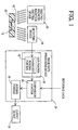
give information on the ophthalmic lens. Fig. 1 schematically
shows a reading device for reading the identifying mark formed
in the ophthalmic lens. The reading device includes an
electromagnetic radiation emitting device 10, a fluorescent image
detecting device 14, an image data processing device 28, and an
output device 38.
The electromagnetic radiation emitting device 10
emits a suitable light (an excitation light) having a
predetermined wavelength, which is incident upon an ophthalmic
lens with the identifying mark (marked ophthalmic lens), in the
form of a marked contact lens 12 made of a known polymer
material. The excitation light causes the marked contact lens
12 to emit a self-fluorescent light, owing to excitation of the
polymer material of the marked contact lens 12. Any known
light emitting device such as a xenon lamp, a mercury lamp, a
deuterium lamp, a tungsten-iodine lamp, or a laser radiation
emitting device is suitably employed as the electromagnetic
radiation emitting device 10. The luminance or intensity of the
fluorescent light which is emitted from the ophthalmic lens by
exposure to the excitation light generally increases with an
increase in the intensity of the excitation light. Although the
luminance of the self-fluorescent light emitted from the
ophthalmic lens is advantageously increased by application of the
excitation light having a relatively high degree of intensity, it is
needless to mention that the ophthalmic lens may suffer from an
undesirable change in its quality due to exposure to the
excitation light with an excessively high intensity.
The wavelength of the excitation light which
irradiates the marked ophthalmic lens such as the marked
contact lens 12 is not particularly limited, provided that the
excitation light can generate the self-fluorescent light in the lens
due to the excitation of the lens material itself. As the
excitation light, a UV light having a wavelength in a range of
200-400 nm is preferably employed. The UV light may be a line
spectrum of a narrow band width, a continuous spectrum of a
relatively broad band width, or may be composed of a plurality of
line spectra. The self-fluorescent light emitted from the marked
ophthalmic lens by exposure to such a UV light is generally a
light having a wavelength in a range of 340-470 nm.
For irradiating the marked contact lens 12 with the
light in the desired wavelength range described above, an optical
filter may be interposed between the electromagnetic radiation
emitting device 10 and the marked contact lens 12. The optical
filter is adapted to selectively pass therethrough only the
excitation light in the desired wavelength range for exciting the
material of the marked contact lens 12. Since the optical filter
does not pass therethrough a light having a wavelength outside
the desired range, the marked contact lens 12 can be effectively
irradiated with the excitation light in the desired wavelength
range emitted from the device 10.
The fluorescent image detecting device 14 takes
two-dimensional fluorescent image of the marked contact lens 12
while the lens 12 is emitting the self-fluorescent light by
exposure to the excitation light applied from the electromagnetic
radiation emitting device 10. As the detecting device 14, any
known image-taking device (light detecting device) such as a
CCD cameral or a photodiode can be suitably used, provided that
the device is adapted to detect the self-fluorescent light emitted
from the marked contact lens 12 and convert the light signal of
the self-fluorescent light into the electric signal. The image-taking
device may be provided with a lens such as a microscope
or a camera, for obtaining a significantly clear fluorescent image
of the marked contact lens 12.
When the detecting device 14 is not arranged to
detect only the light in the desired wavelength range, the
detecting device 14 is preferably equipped with an optical filter or
filters adapted to pass therethrough only the light in the desired
wavelength range. The detecting device 14 with the optical
filter(s) can selectively detect only the self-fluorescent light
emitted from the marked contact lens 12, and does not pass
therethrough a redundant light, i.e., the excitation light having a
considerably higher degree of intensity than the self-fluorescent
light emitted from the marked contact lens 12. Accordingly, the
obtained fluorescent image of the marked contact lens 12 has a
high degree of contrast.
One example of an image-taking system including
the electromagnetic radiation emitting device 10 and the
detecting device 14 for taking the fluorescent image of the
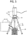
marked contact lens 12 is shown in Fig. 2. In Fig. 2, the
reference numeral 16 indicates a mercury-xenon lamp equipped
with a band pass filter which passes a UV light whose
wavelength is in a range of 330-380 nm. The mercury-xenon
lamp 16 corresponds to the electromagnetic radiation emitting
device 10 in Fig. 1. The UV light emitted from the
mercury-xenon lamp 16 is applied through a UV light guide 18
toward the upper surface of the marked contact lens 12.
The self-fluorescent light emitted from the marked
contact lens 12 is detected by the detecting device 14 which
includes a camera lens 20 and a digital CCD camera 22 and
which is equipped with a UV cut-off filter. In the present
embodiment, the detecting device 14 is placed on a camera stand
24 and located above the marked contact lens 12, as shown in Fig.
2. The marked contact lens 12 is accommodated in a container
40 which will be described, and the container 40 is placed on a
stage in the form of an elevator 26.
The fluorescent image of the marked contact lens 12
detected as described above is fed to an image data processing
device 28 which is constituted by any suitable known
microcomputer such as a personal computer. The image data
processing device 28 includes a character reading portion 32
functioning as an optical character recognition (OCR) portion 30,
a comparison portion 34 for comparing the obtained data with
reference data, and a judging portion 36 for judging whether the
obtained data are identical with the reference data.
Image data representative of the fluorescent image
are first applied to the character reading portion 32 of the OCR
portion 30 to read the identifying mark formed in the marked
contact lens 12 such as characters or figures which represent the
specifications of the lens (e.g., a base curve value, a diameter of
the lens, etc.) and a production number of the lens. The
character reading portion 32 utilizes a known character
recognition function such as a pattern matching function or a
neuro-learning function.
The character data which represent the information
on the marked contact lens 12 read by the character reading
portion 32 are applied to the comparison portion 34 where the
obtained character data (obtained lens information) are
compared with reference data (prepared lens information). For
instance, the reference data are read from a bar code and a
two-dimensional code given on a product label, an ID chip, a data
storage medium such as FD, MO, CD-R(W), or a data base stored
in a host computer. The comparison portion 32 reads suitable
reference data depending upon the character data which are read
by the character reading portion 32. When the identifying mark
formed in the marked contact lens 12 represents an optical power
value of the lens, a desired optical power value is read as the
reference data.
The judging portion 36 judges whether the obtained
character data are identical with the reference data. The result
of the judgment is output to an output device 38 in the form of a
display, a printer, a warning device, etc. The obtained character
data and the result of the judgment may be stored in a an ID chip,
a data storage medium such as FD, MO, CD-R(W), etc., or a data
base in a host computer.
On the basis of the judgment made as described
above, the ophthalmic lens which has character data different
from the reference data is distinguished from the desired
ophthalmic lens having the character data identical with the
reference data. Accordingly, the present arrangement effectively
avoids the conventionally experienced problem of delivering, to a
user, improper lenses having specifications not suitable to the eye
of the specific user. Further, the mass-produced ophthalmic
lenses having different specifications are effectively
distinguished from one another in the production line.
In the present method using the identifying mark
reading device constructed as described above, the marked
ophthalmic lens (marked contact lens 12) is uniformly irradiated
with the predetermined excitation light over the entire surface
thereof, and the self-fluorescent light emitted from the lens upon
irradiation with the excitation light is detected to give the
fluorescent image of the lens. The thus obtained fluorescent
image of the lens has a higher degree of contrast than a directly
photographed image of the lens, whereby the identifying mark is
represented by the fluorescent image with a high degree of clarity.
Therefore, the identifying mark formed in the ophthalmic lens
can be easily recognized, so that the information of the marked
ophthalmic lens can be advantageously obtained.
In the present method described above, the
identifying mark clearly represented by the fluorescent image
can be automatically read, for thereby permitting a speedy and
continuous reading of the identifying mark formed in each of the
mass-produced ophthalmic lenses, and significantly reducing the
labor cost required for reading the identifying mark, so that the
cost for manufacture of the ophthalmic lens can be effectively
reduced.
The marked contact lens 12 is immersed in a liquid
medium 42 such as a saline solution or a contact lens storing
liquid. The liquid medium 42 is accommodated in the container
40 which has a cylindrical shape with a relatively small depth.
The excitation light is applied to the marked contact lens 12
while the lens 12 is immersed in the liquid medium 42
accommodated in the container 40. The material of the
container 40 is preferably selected from among those which do
not emit a fluorescent light by exposure to the excitation light,
for obtaining the fluorescent image of the lens 12 having a high
degree of contrast. In view of this, it is preferable to employ, as
the material of the container 40, a quartz glass or a any known
metallic material such as stainless steel or aluminum. Those
materials are not excited by the UV radiation having a
wavelength of 200-400 nm. The material of the container 40 is
not limited to those described above, but any other known
materials which emit a fluorescent light by exposure to the
excitation light may be used, as long as the fluorescent light
emitted from the material of the container 40 does not prevent
the reading or recognition of the identifying mark represented by
the fluorescent image of the lens 12.
In addition, it is preferable that the liquid medium
42 in which the marked contact lens 12 is immersed does not
emit a fluorescent light by exposure to the excitation light. If
the marked contact lens 12 were stained, the identifying mark
formed in the lens 12 would not be clearly recognized. In view of
this, it is preferable that the identifying mark should be read
while the lens 12 is kept clean.
While the present invention has been described in
detail in its presently preferred first embodiment directed to the
method of reading the identifying mark formed in the ophthalmic
lens, it is to be understood that the invention is not limited to the
details of the first embodiment.
In the illustrated first embodiment, the optical
character recognition (OCR)
portion 30 reads the characters as
the identifying mark formed in the
marked contact lens 12, so
that the information on the
marked contact lens 12 is obtained.
In addition to the characters, other identifying marks such as
figures, symbols, etc. can be read. For instance, code marks
such as a bar code and two dimensional codes such as a veri code
can be read by using a reading device adapted to read the code
marks, for thereby obtaining coded information of the lens.
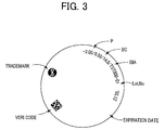
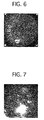
Examples of the identifying mark or information are shown in
the following TABLE 1. It is noted that the identifying marks
are not limited to those indicated in the TABLE 1. Fig. 3
schematically shows one example of the marked contact lens in
which the identifying marks are formed.
| Information on the ophthalmic lens | Examples of the identifying mark |
| Kind of the ophthalmic lens | MENICON Z, MENICON SUPER EX, MENICON SOFT MA (Product Name) |
| Base curve (BC) (radius of curvature at vertex) | 8.00 (mm) |
| Diameter (DIA) | 8.8 (mm) |
| Center thickness | 0.15 (mm) |
| Optical power (P) | 3.00 (diopter) |
| Manufacturing date or number | 2000. 01.01 |
| Material | PMMA |
| Storing liquid | Saline solution |
| Expiration date | 2010.01.01 |
| Manufacturing Plant | Seki-Plant, Seki, Gifu-ken |
| Lot No. | DE0892272 |
| Two dimensional code | (two dimensional data of at least one of those described above) |
The optical filters such as the band pass filter and
the cut-off filter may be disposed otherwise. For instance, the
optical filters may be disposed outside the electromagnetic
radiation emitting device 10 and the detecting device 14,
respectively, provided that the optical filters are located between
the excitation light source and the marked contact lens, and
between the image-taking device and the marked contact lens.
The optical filters are not essential, but may be suitably provided
depending upon the excitation light source and the image-taking
device.
The structure of the image data processing device 28
is not limited to that in the illustrated first embodiment, but may
be suitably determined depending upon the forms of the
identifying marks to be read.
In the illustrated first embodiment, the identifying
mark is automatically read or recognized in the image data
processing device 28. The identifying mark may be read
manually by the worker from the output fluorescent image of the
lens. In this case, for permitting the worker to easily recognize
the identifying mark, it is preferable that the fluorescent image
of the lens detected by the detecting device 14 is represented by a
plurality of colors corresponding to respective values of
luminance at local portions of the ophthalmic lens.
Alternatively, it is preferable that the output device is arranged
to provide an enlarged fluorescent image of the lens.
In the illustrated first embodiment, the
electromagnetic radiation emitting device 10 and the fluorescent
image detecting device 14 are located above the marked contact
lens 12, shown in Fig. 1, such that the excitation light was
applied toward the upper surface of the marked contact lens 12,
and such that the self-fluorescent light emitted from the marked
contact lens 12 is detected on the upper side of the lens 12. The
locations of the devices 10, 14 with respect to the marked contact
lens 12 are not particularly limited, provided that the self-fluorescent
light emitted from the lens 12 by exposure to the
excitation light can be effectively detected. For instance, the
excitation light may be applied from the device 10 toward the
upper surface of the lens 12 while the device 14 located below the
lens 12 may detect the self-fluorescent light on the lower side of
the lens 12, as shown in Fig. 4. Further, the electromagnetic
radiation emitting device 10 and the detecting device 14 may be
located above the lens 12 with the container 40 being interposed
therebetween.
In the illustrated first embodiment, the marked
contact lens 12 is accommodated in the container 40 with its base
curved surface facing upward. The marked contact lens 12 may
be positioned with its front curved surface facing upward.
In the illustrated first embodiment, the identifying
mark is read with the marked contact lens 12 being immersed in
a predetermined amount of the liquid medium 42 accommodated
in the container 40. The structure of the container 40 is not
limited to that in the illustrated embodiment. Further, the
container 40 and the liquid medium 42 are not essential.
In the illustrated first embodiment, the identifying
mark is read while the container 40 in which the marked contact
lens 12 is accommodated is placed on the elevator 38, as shown in
Figs. 2 and 5. In place of the elevator 38, a known transferring
device such as a belt conveyor may be used, for thereby
permitting a continuous reading of the identifying marks formed
in each of a plurality of marked contact lenses.
Referring next to Figs. 8-11, there will be explained
a second and a third embodiment of the present invention, which
are directed to a method of obtaining a thickness of an
ophthalmic lens, as another example of the particulars which
give information on the ophthalmic lens. In these second and
third embodiments, the same reference numerals as used in the
above-described first embodiment of Figs. 1-7 are used to identify
the corresponding components, and a detailed description of
which is dispensed with.
Fig. 8 schematically shows a thickness measuring
device, which is constructed according to the second embodiment,
for measuring the thickness of an ophthalmic lens. The
thickness measuring device of Fig. 8 includes the electromagnetic
radiation emitting device 10, the fluorescent image detecting
device 14 (which are the same as those explained in the
above-described first embodiment), a computer 116, and an
output device 124. The wavelength of the excitation light for
irradiating the ophthalmic lens in the form of a contact lens 112
and the wavelength of the self-fluorescent light emitted from the
contact lens 112 are within the respective preferred ranges
described above with respect to the first embodiment. In this
second embodiment, too, a suitable optical filter may be
interposed between the device 10 and the contact lens 112 for the
purpose of effectively irradiating the contact lens 112 with the
desired excitation light. As in the above-described first
embodiment, the detecting device 14 for detecting the fluorescent
image of the contact lens 112 is preferably equipped with a
suitable optical filter or filters for the purpose of obtaining the
fluorescent image of the contact lens 112 with a high degree of
contrast. The structure of the image-taking system including
the electromagnetic radiation emitting device 10 and the
fluorescent image detecting device 14 is similar to that shown in
Fig. 2 described above with respect to the first embodiment, and
a detailed description of which is dispensed with.
The fluorescent image of the contact lens 112
detected by the detecting device 14 is fed to the computer 116
which includes a luminance determining portion 118 for
determining a luminance value at a predetermined thickness
measuring portion, a thickness determining portion 120 for
determining the thickness at the thickness measuring portion on
the basis of the luminance value determined by the luminance
determining portion 118, and a converting portion 122 for
converting the detected fluorescent image of the contact lens 112
into a color image. The computer 116 is constituted by any
known microcomputer such as a personal computer.
More specifically described, image data
representative of the fluorescent image are applied to the
luminance determining portion 118 and the converting portion
122, respectively. The detected fluorescent image of the contact
lens 112 represents a distribution of respective luminance values
of local portions of the contact lens 112. The luminance
determining portion 118 first determines a position of the
predetermined thickness measuring portion of the lens in the
fluorescent image, on the basis of suitably input data (e.g.,
numerical values) indicative of the position of the thickness
measuring portion, and then obtains the luminance value at the
thickness measuring portion on the basis of the distribution.
The thickness determining portion 120 determines
the thickness of the thickness measuring portion on the basis of
the obtained luminance value and according to reference data in
the form of a predetermined relationship between the thickness
of the thickness measuring portion and the luminance value of
the self-fluorescent light generated by irradiation with the
excitation light. One example of the reference data is a
calibration curve which is obtained based on a finding that there
is a predetermined correlation between the thickness of the
ophthalmic lens and the luminance of the self-fluorescent light
emitted from the material of the ophthalmic lens. The
calibration curve is obtained in the following manner, for
instance. Initially, there are prepared a plurality of plates
which are formed of the same material as the ophthalmic lens
and which have mutually different thickness values. The
luminance values are determined for each of the different plates
in a manner similar to that in detecting the fluorescent image of
the contact lens 112 described above. The determined
luminance values are plotted in relation to the respective
thickness values, for thereby providing the calibration curve
indicating the predetermined relationship between the thickness
of the ophthalmic lens and the luminance of the self-fluorescent
light emitted from the ophthalmic lens. The thickness of the
thickness measuring portion is determined on the basis of the
luminance value determined by the luminance determining
portion 18 and according to the reference data (predetermined
relationship) obtained as described above. Since the reference
data are used every time when the thickness of the ophthalmic
lens is measured, the reference data are preferably stored in a
magnetic disk such as a hard disk or a floppy disk, or a known
data storage medium such as a magneto-optical disk, a photo
disk, or an IC card.
The thickness of the thickness measuring portion
determined as described above is output to the output device 124
such as a display device and a printer, so that the worker can
recognize the thickness of the thickness measuring portion of the
contact lens 112.
The fluorescent image of the contact lens 112
applied to the converting portion 122 is represented by a
distribution of a plurality of different colors or color gradation
values corresponding to respective values of luminance of
infinitesimal local portions or pixel areas of the contact lens 112.
The output device 124 outputs the fluorescent image of the
contact lens 112 represented by the distribution of different
colors, whereby the worker can easily recognize the distribution
of the luminance values of the contact lens 112. The present
second embodiment may be modified such that the thickness of
any desired portion of the contact lens 112 can be quickly
recognized according to a prepared relationship among the
thickness of the ophthalmic lens, the luminance of the self-fluorescent
light, and the color gradation value.
According to the present embodiment, the
ophthalmic lens is uniformly irradiated with the predetermined
excitation light over the entire surface thereof, and the
fluorescent image of the lens which represents the distribution of
the luminance values of the local portions of the lens is detected
while the lens is emitting the self-fluorescent light. The
thickness of the predetermined thickness measuring portion can
be obtained on the basis of the distribution. Accordingly, the
thickness of the ophthalmic lens can be easily obtained in a
non-contact manner, namely, without using any members in
contact with the ophthalmic lens, for thereby effectively avoiding
the conventionally experienced risk of damaging the lens surface.
Further, the present method permits an accurate measurement
of the thickness, e.g., the optical center thickness, of various
ophthalmic lenses such as a mono-focal lens which has the
smallest thickness at its geometrical center, a toric and a bifocal
lens which have a thin-walled portion at its lower or upper
portion, and other lenses whose optical center is offset from its
geometrical center. Unlike the conventional thickness
measuring method using the ultrasonic wave, the present
method significantly reduces a required time for measuring the
thickness of the ophthalmic lens.
In the present method, the self-fluorescent light is
detected over the entire surface of the ophthalmic lens, rather
than in a predetermined limited portion of the lens. Accordingly,
the position of the desired thickness measuring portion can be
easily and accurately determined in the fluorescent image. In
addition, not only the center thickness, but also the thickness at
any desired portion of the ophthalmic lens can be obtained in a
single measuring operation.
Since the fluorescent image of the ophthalmic lens is
represented by a plurality of different colors corresponding to the
respective luminance values of local portions of the lens, the
thickness of the lens or the distribution of the luminance values
of the ophthalmic lens can be easily recognized.
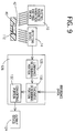
The structure of the thickness measuring device is
not limited to that in the illustrated second embodiment, but may
be modified as shown in Fig. 9, for instance. In Fig. 9, the same
reference numerals as used in Fig. 8 are used to identify the
corresponding components, which will not be described below to
avoid redundant description.
The thickness measuring device of Fig. 9
constructed according to the third embodiment of the invention
has a computer 126 which is different from the computer 116 of
the thickness measuring device of Fig. 8. The computer 126 of
the thickness measuring device according to this third
embodiment includes a luminance determining portion 128, a
thickness determining portion 130, and a converting portion 132.
Like the computer 116 of Fig. 8, the computer 126 of Fig. 9 is
constituted by any known microcomputer such as a personal
computer.
More specifically described, image data
representative of the fluorescent image of the contact lens 112
detected by the detecting device 14 are initially applied to the
luminance determining portion 128. The fluorescent image
represents a distribution of respective luminance values of the
infinitesimal local portions or pixel areas of the contact lens 112.
The luminance determining portion 128 determines the
respective luminance values of the local portions of the contact
lens 112 on the basis of the distribution.
The obtained luminance values of the local portions
of the contact lens 112 are applied to the thickness determining
portion 130, and the thickness values corresponding to the
obtained luminance values of the local portions of the contact
lens 112 are determined according to the prepared reference data
described above.
The thickness values determined for the local
portions of the contact lens 112 are applied to the converting
portion 132. In the converting portion 132, the distribution of
the thickness values of the contact lens 112 is represented by a
plurality of different colors or color gradation values
corresponding to the respective thickness values, and accordingly
the luminance values, of the infinitesimal local portions of the
contact lens 112. The output device 124 outputs the fluorescent
image of the contact lens 112 represented by the distribution of
different colors, whereby the worker can easily obtain the
thickness at any desired portion of the contact lens 112.
The thickness measurement of the contact lens 112
is conducted while the lens 112 is accommodated in the container
40 shown in Figs. 8 and 9. As in the illustrated first
embodiment of Figs. 1-7, the material of the container 40 is not
particularly limited, but is preferably selected from among those
which do not emit a fluorescent light by exposure to the
excitation light, for obtaining the thickness of the contact lens
112 with high accuracy. It is preferable to use, as the material
of the container 40, a quartz glass or any known metallic
material such as stainless steel or aluminum. Those materials
are not excited by the UV radiation having a wavelength of
200-400 nm. When the container 40 is formed of a material
which emits a fluorescent light by exposure to the excitation light,
the luminance values of the fluorescent image of the contact lens
112 need to be determined by taking account of the luminance of
the fluorescent light emitted from the material of the container,
or the container formed of the material which emits the
fluorescent light needs to be used for obtaining the reference
data.
In addition, it is preferable that the liquid medium
42 in which the contact lens 112 is immersed does not emit a
fluorescent light by exposure to the excitation light. If the
contact lens 112 and the container 40 were stained, it would be
difficult to accurately obtain the thickness of the contact lens 112.
In view of this, it is preferable that the thickness measurement is
conducted with the lens being kept clean, at a suitable timing
such as during its manufacture or prior to its shipment.
While the present invention has been described in
detail in its presently preferred second and third embodiments
directed to the method of obtaining the thickness of the
ophthalmic lens, it is to be understood that the invention is not
limited to the details of the second and third embodiments. The
present method of obtaining the thickness of the ophthalmic lens
may be practiced by using a thickness measuring device different
from those shown in Figs. 8 and 9.
In the illustrated second and third embodiments,
the luminance values in the fluorescent image of the ophthalmic
lens are obtained for the infinitesimal local portions or pixel
areas. The luminance values may be obtained for a desired area
of the thickness measuring portion, which has various shapes
such as a circle (having a diameter of 1µm, for instance), a cross,
a rectangle, a square, a polygonal, etc. In obtaining the
thickness of the thickness measuring portion which is composed
of a plurality of pixels, the luminance values of the respective
pixels are preferably averaged, and the average value of
luminance is used to determine the thickness of the thickness
measuring portion, for an improved measuring accuracy. The
thickness measuring portion may be determined otherwise, for
instance, by pointing a desired portion of the fluorescent image of
the lens indicated on the monitor.
In addition to the thickness at a predetermined
portion of the ophthalmic lens, the smallest or the largest
thickness of the ophthalmic lens and the positions in the lens
which give the largest and small thickness, respectively, can be
obtained from the intensity (luminance) of the detected self-fluorescent
light.
In the illustrated second and third embodiments,
the converting portions 122, 132 are arranged such that the
fluorescent image of the ophthalmic lens detected by the
detecting device 14 is represented by a plurality of colors or color
gradation values corresponding to the respective luminance
values of local portions of the lens, whereby the color image of the
lens is output to the output device 124. The converting portion
122, 132 is not an essential component in the present invention.
The optical filters such as the band pass filter and
the cut-off filter may be disposed otherwise. For instance, the
optical filters may be disposed outside the electromagnetic
radiation emitting device 10 and the detecting device 14,
respectively, provided that the optical filters are located between
the excitation light source and the ophthalmic lens, and between
the image-taking device and the ophthalmic lens. The optical
filters are not essential, but may be suitably provided depending
upon the excitation light source and the image-taking device. If
the excitation light source is arranged to emit only a light in the
desired wavelength range, the optical filters need not be
provided.
The structures of the computers 116, 126 are not
limited to those described above. For instance, the thickness of
the thickness measuring portion may not be determined by the
computers 116, 126, but may be determined by the worker on the
basis of the obtained luminance and according to the calibration
curve, for instance.
In the illustrated second and third embodiments,
the entire surface of the ophthalmic lens is irradiated with the
excitation light, and the fluorescent image of the ophthalmic lens
is detected. Only a desired thickness measuring portion may be
irradiated with the excitation light for detecting the self-fluorescent
light only from the desired thickness measuring
portion.
In the illustrated second and third embodiments,
the electromagnetic radiation emitting device 10 and the
detecting device 14 are located above the ophthalmic lens (112).
The electromagnetic radiation emitting device 10 and the
detecting device 14 may be located in opposed relation to each
other with the ophthalmic lens being interposed therebetween.
In measuring the thickness of the contact lens (112),
the contact lens 112 may be accommodated in the container 40
with its base curved surface facing upward, as shown in Figs. 8
and 9, or the contact lens 112 may be positioned with its front
curved surface facing upward.
In the illustrated second and third embodiments,
the principle of the present invention is applied to the toric lens
and the bifocal lens. The principle of the present invention is
applicable to contact lenses and intraocular lenses having
various configurations and formed of various materials.
Referring next to Figs. 12-16, there will be described
a fourth embodiment of the present invention which is directed to
a method of detecting an angular position of an ophthalmic lens,
as another example of the particulars which give information on
the ophthalmic lens. The angular position is defined, for
instance, by a position of one of the thickest circumferential
portion, a distant vision correction region, and a near vision
correction region of the ophthalmic lens, in its circumferential
direction. In this fourth embodiment, the same reference
numerals as used in the above-described first embodiment of Figs.
1-7 are used to identify the corresponding components, and a
detailed description of which is dispensed with.
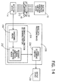
Fig. 12 schematically shows an angular position
detecting device, which is constructed according to the fourth
embodiment, for detecting the angular position of an ophthalmic
lens. The angular position detecting device of Fig. 12 includes
the electromagnetic radiation emitting device 10, the fluorescent
image detecting device 14 (which are the same as those explained
in the above-described first embodiment), an image data
processing device 228, and an output device 238. The
wavelength of the excitation light for irradiating the ophthalmic
lens in the form of a contact lens 212 and the wavelength of the
self-fluorescent light emitted from the contact lens 212 are within
the respective preferred ranges described above with respect to
the first embodiment. In this fourth embodiment, too, a suitable
optical filter may be interposed between the device 10 and the
contact lens 222 for the purpose of effectively irradiating the
contact lens 212 with the desired excitation light. As in the
above-described first embodiment, the detecting device 14 for
detecting the fluorescent image of the contact lens 212 is
preferably equipped with a suitable optical filter or filters for the
purpose of obtaining the fluorescent image of the contact lens 212
with a high degree of contrast. The structure of the image-taking
system including the electromagnetic radiation emitting
device 10 and the fluorescent image detecting device 14 is similar
to that shown in Fig. 2, and a detailed description of which is
dispensed with.
Image data representative of the fluorescent image
detected by the detecting device 14 may be directly output to the
output device 238. In the present embodiment, however, the
image data representative of the fluorescent image are applied to
the image data processing device 228. The fluorescent image
represents a distribution of respective luminance values of local
portions of the contact lens 212. The image data processing
device 228 includes a reference radial direction determining
portion 234 which comprises a smoothing means 230 for
smoothing the luminance values of the local portions of the
fluorescent image and a reference radial direction determining
means 232 for determining a reference radial direction, and an
angle calculating portion 236 for calculating an angle defined by
the reference radial direction and a horizontal axis L of the
fluorescent image of the contact lens 212. The reference radial
direction is defined by the geometrical center of the lens and the
thickest circumferential portion of the lens. The thickest
circumferential portion of the lens is aligned with the reference
radial direction. The image data processing device 228 is
constituted by any known microcomputer such as a personal
computer.
The image data representative of the fluorescent
image of the contact lens 212 are initially applied to the
smoothing means 230, so that the fluorescent image of the
contact lens 212 is subjected to a smoothing treatment.
Described in detail, the luminance values at the local portions of
the lens 212, especially at the portions having relatively high
luminance values, are smoothed for the purpose of averaging the
luminance values at those portions to minimize variations in the
luminance values, whereby the distribution of the luminance
values in the fluorescent image of the contact lens 212 can be
clearly recognized. Fig. 13 schematically shows the smoothed
fluorescent image of the contact lens 212.
The smoothed fluorescent image of the contact lens
212 is applied to the reference radial direction determining
means 232 to determine, as the reference radial direction, a
radial direction extending from the geometric center of the lens
toward a circumferential position of the lens exhibiting high
luminance values, as shown in Fig. 3.
The determined reference radial direction is applied
to the angle calculating portion 236 to calculate an angle a
defined by the reference radial direction and the horizontal axis
L of the fluorescent image of the contact lens 212.
The calculated angle α is output to the output device
238 such as a known display device or a printer, so that the
worker can recognize the reference radial direction. According
to the present embodiment, the angular position of the contact
lens 212 defined by the reference radial direction which extends
from the geometrical center of the lens toward the thickest
circumferential portion of the lens can be accurately detected,
whereby various characteristic inspections of the contact lenses
212 can be conducted with high accuracy. In the astigmatism
correction contact lens, a spherical power, a cylindrical power, an
orientation of an astigmatic axis, and an amount of prism are
accurately detected based on the determined angular position.
The presbyopia correction contact lens is examined for its
circumferential positions of the distant and near vision correction
regions based on the determined angular position.
The present method permits detection of the
angular position of a special contact lens which has
circumferential portions having respective different thickness
values and whose fluorescent image has a distribution of the
luminance values shown in Fig. 3, for instance. Examples of the
special contact lens include an astigmatism correction contact
lens whose typical example is a toric lens, and a presbyopia
correction contact lens whose typical example is a multifocal lens
providing near and distant vision correction powers. It is noted
that the present method is applicable to any other ophthalmic
lenses which have circumferential portions having respective
different thickness values by provision of the prism ballast
mechanism, for example.
In the present method of detecting the angular
position of the ophthalmic lens, the entire surface of the
ophthalmic lens is irradiated with a suitable excitation light, and
the fluorescent image of the lens is detected while the lens is
emitting the self-fluorescent light by exposure to the excitation
light. On the basis of the fluorescent image which represents
the distribution of the luminance values on the surface of the
ophthalmic lens, the reference radial direction and the angle α
are determined, for thereby permitting an accurate detection of
the angular position of the ophthalmic lens.
The present method permits an automatic and
continuous detection of the angular position of each of a plurality
of ophthalmic lenses, for thereby considerably reducing a time
and a labor cost required for detecting the angular position of the
ophthalmic lens.
In the present method wherein the self-fluorescent
light emitted from the ophthalmic lens itself is detected, the
fluorescent image of the ophthalmic lens is considerably clear, as
compared with an image of an ophthalmic lens which is obtained
by irradiating the lens with a visible light, and detecting a
portion of the light which is reflected by the lens or which is not
absorbed by the lens. Accordingly, unlike the conventional
method, the present method permits an accurate detection or
determination of the angular position of the lens (e.g., the
reference radial direction).
As in the above-described first embodiment of Figs.
1-7, the angular position of the contact lens 212 is detected with
the lens 212 being immersed in the liquid medium 42 such as a
saline solution, distilled water or a suitable contact lens storing
liquid, as shown in Fig. 12. The liquid medium 42 is
accommodated in the container 40 which has a cylindrical shape
with a relatively small depth. The excitation light is applied to
the contact lens 212 while the contact lens 212 is immersed in
the liquid medium 42 accommodated in the container 40. As in
the illustrated first embodiment, the material of the container 40
is not particularly limited, but is preferably selected from among
those which do not emit a fluorescent light by exposure to the
excitation light, for detecting the angular position of the
ophthalmic lens with high accuracy. It is preferable to use, as
the material of the container 40, a quartz glass or any known
metallic material such as stainless steel or aluminum. Those
materials are not excited by the UV radiation having a
wavelength of 200-400 nm. The material of the container 40 is
not limited to those described above, but any other known
materials which emit a fluorescent light by exposure to the
excitation light may be used, as long as the angular position can
be effectively detected from the fluorescent image representing
the distribution of the luminance values on the surface of the
ophthalmic lens, without being adversely influenced by the
fluorescent light emitted from the material of the container.
In addition, it is preferable that the liquid medium
42 in which the contact lens 212 is immersed does not emit a
fluorescent light by exposure to the excitation light. If the
contact lens 212 and the container 40 were stained, it would be
difficult to accurately detect the angular position of the contact
lens 212. In view of this, it is preferable that the detection of
the angular position of the contact lens 212 is conducted with the
contact lens 212 being kept clean, at a suitable timing such as
during its manufacture or prior to its shipment.
Preferably, the contact lens 212 is accommodated in
the container 40 such that the contact lens 212 is prevented from
rotating therein, for the subsequent various inspections on the
lens.
While the present invention has been described in
detail in its presently preferred fourth embodiment directed to
the method of detecting the angular position of the ophthalmic
lens, it is to be understood that the invention is not limited to the
details of the fourth embodiment.
In the illustrated fourth embodiment, the reference
radial direction and the angle α which is defined by the reference
radial direction and the horizontal axis L of the special contact
lens are detected. On the basis of the obtained distribution of
the luminance values on the surface of the ophthalmic lens and
the obtained angular position of the lens, it is possible to detect,
in the special contact lens, the respective circumferential
positions of the near vision correction region and the distant
vision correction region. Further, it is possible, in the
presbyopia correction contact lens, to detect respective
circumferential positions of two optical portions, and to
determine that one and the other of the two optical portions are
assigned to the corresponding one and the other of the near
vision correction region and the distant vision correction region.
The optical filters such as the band pass filter and
the cut-off filter may be disposed otherwise. For instance, the
optical filters may be disposed outside the electromagnetic
radiation emitting device 10 and the detecting device 14,
respectively, provided that the optical filters are located between
the excitation light source and the ophthalmic lens, and between
the image-taking device and the ophthalmic lens. The optical
filters are not essential, but may be suitably provided depending
upon the excitation light source and the image-taking device.
The structure of the image data processing device
228 is not limited to that of the illustrated fourth embodiment,
but may be suitably modified depending upon the angular
position to be detected, e.g., the reference radial direction and the
angle α, and the circumferential positions of the near and distant
vision correction regions.
While the angular position of the ophthalmic lens
such as the reference radial direction is detected by the image
data processing device 228 in the illustrated fourth embodiment,
the angular position may be detected by a manual operation of
the worker on the basis of the output distribution of the
luminance values represented by the fluorescent image of the
ophthalmic lens. In this case, the fluorescent image is
preferably represented by a plurality of colors or color gradation
values corresponding to the respective values of the local portions
of the ophthalmic lens, for easier recognition of the distribution of
the luminance values.
In the illustrated fourth embodiment, the
electromagnetic radiation emitting device 10 and the detecting
device 14 are located above the contact lens 212, shown in Fig. 12,
such that the excitation light was applied toward the upper
surface of the contact lens 212, and such that the self-fluorescent
light emitted from the contact lens 212 is detected on the upper
side of the lens. The locations of the devices 10, 14 with respect
to the contact lens 212 are not particularly limited, provided that
the self-fluorescent light emitted from the contact lens 212 by
exposure to the excitation light can be effectively detected. For
instance, the excitation light may be applied from the device 10
toward the upper surface of the contact lens 212 while the device
14 located below the contact lens 212 may detect the self-fluorescent
light on the lower side of the contact lens 212, as
shown in Fig. 14. Alternatively, the electromagnetic radiation
emitting device 10 may be located below the contact lens 212
while the detecting device 14 may be located above the contact
lens 212.
In the illustrated fourth embodiment, the contact
lens 212 is accommodated in the container 40 with its base
curved surface facing upward. The contact lens 212 may be
positioned with its front curved surface facing upward.
In the illustrated fourth embodiment, the angular
position of the contact lens 212 is detected while the contact lens
212 is immersed in a predetermined amount of the liquid
medium 42 accommodated in the container 40. The structure of
the container 40 is not limited to that in the illustrated
embodiment. Further, the container 40 and the liquid medium
42 are not essential.
In the illustrated fourth embodiment, the angular
position of the contact lens 212 is detected while the container 40
in which the contact lens 212 is accommodated is placed on the
elevator 38, as shown in Fig. 2. In place of the elevator 38, a
known transferring device such as a belt conveyor may be used,
for thereby permitting a continuous detection of the angular
position of each of a plurality of contact lenses.
EXAMPLES
There will be described some examples of the
present invention to further clarify the present invention.
However, it is to be understood that the present invention is not
limited to the details of the following examples and the presently
preferred embodiments described above, but may be embodied
with various changes, modifications and improvements, which
may occur to those skilled in the art, without departing from the
spirit of the present invention.
<Example 1>
Initially, there is prepared, as a sample lens, a new
highly water-swollen soft contact lens in which an identifying
mark "-3.00" which represents the optical power of the lens is
engraved with a laser radiation. This sample contact lens has a
base curve value of 8.50 mm and a diameter of 14.0 mm. By
using an identifying mark reading device described below, the
identifying mark formed in the sample lens was read in the
following manner. As the reference data which are compared
with the data to be obtained from the fluorescent image of the
sample lens, "-3.00" is used.
-Reading device-
- ORCA AQUACOSMOS package available from "KABUSHIKI
KAISHA HAMAMATSU PHOTONICS, Japan
- image-taking device: digital CCD camera (C-4742-95-12NR)
F mount lens (f=55 mm, F2.8S) - image analyzing device: image data processing device (C7746-43E)
- image analyzing software: AQUACOSMOS BASIC SOFTWARE
(U 7501)
OCR SOFTWARE (self-made program
available from Menicon Co., Ltd., Japan)
- Excitation light source: mercury-xenon lamp 200W
- Optical filter :
- <excitation light source>
330-380UV excitation filter - <image-taking device>
sky light filter
(cut-off filter adapted to inhibit transmission of a light
whose wavelength is not larger than 390 nm) and
400 absorption filter
(cut-off filter adapted to inhibit transmission of a light
whose wavelength is not larger than 400 nm)
The sample contact lens was immersed in a
predetermined amount of a saline solution accommodated in a
blister case (40) with its base curved surface facing upward, as
shown in Fig. 2. The blister case (40) accommodating the
sample contact lens therein was placed on a stage of the
detecting device (14) constituted by the digital CCD camera (22)
equipped with the F mount lens (20).
The excitation light was applied toward the upper
surface of the sample contact lens, and the self-fluorescent light
emitted from the lens by the exposure to the excitation light was
detected on the upper side of the lens. As the electromagnetic
radiation emitting device (10), a mercury-xenon lamp (200W) was
used. This mercury-xenon lamp is equipped with a 330-380UV
excitation filter which permits transmission of a light having a
wavelength in the neighborhood of 330-380 nm and whose
spectral transmittance in the neighborhood of 340-390 nm is not
less than 60%. The detecting device (14) is equipped with a sky
light filter which inhibits transmission of a light whose
wavelength is smaller than 390 nm and whose spectral
transmittance at a wavelength of not less than 400 nm is not less
than 80%. The detecting device (14) is also equipped with a 400
absorption filter which inhibits transmission of a light whose
wavelength is smaller than 400 nm and whose spectral
transmittance at a wavelength of not less than 420 nm is not less
than 80%.
The image data representative of the fluorescent
image taken by the detecting device (14) constructed as described
above are applied to the image data processing device (computer)
connected to the detecting device (14) via an interface, so that the
identifying mark was read from the fluorescent image of the
sample contact lens, and compared with the prepared reference
data. The identifying mark read from the fluorescent image was
confirmed to be identical with the reference data. The
fluorescent image of the sample contact lens taken by the
detecting device (14) is shown in Fig. 6.
As a comparative example, the sample contact lens
was directly photographed by using a device similar to the device
(14) while the lens was illuminated with a visible light. The
obtained image of the lens is shown in Fig. 7.
As is apparent from Figs. 6 and 7, the identifying
mark is represented by the fluorescent image of the lens with a
higher degree of clarity than the image of the lens which is
directly taken by a camera, whereby the identifying mark can be
effectively recognized.
According to the present method of reading the
identifying mark formed in the ophthalmic lens, the identifying
mark, which is engraved with the laser radiation, for instance,
and which is generally difficult to be recognized by a visual
inspection, is clearly represented by the fluorescent image, so
that the identifying mark formed in the ophthalmic lens can be
easily and effectively recognized.
<Example 2>
Initially, there were prepared, as sample lenses, a
new toric lens ("MENICON 72 TORIC LENS" available from
Menicon Co., Ltd., Japan) and a new bifocal lens ("MENIFOCAL
SOFT 72" available from Menicon Co., Ltd., Japan) having the
respective specifications described below.
MENICON 72 TORIC LENS
base curve: 8.70 mm optical power: -3.00 diameter: 14.0 mm
additional power: -1.75 axis: 180
MENIFOCAL SOFT 72
base curve: 8.10 optical power -3.00 diameter: 13.5 mm
additional power: +3.00 axis:-30
The thickness of each of these two sample lenses was measured
by using a thickness measuring device described below.
-Thickness measuring device-
- ORCA AQUACOSMOS package available from "KABUSHIKI
KAISHA HAMAMATSU PHOTONICS, Japan
- image-taking device: digital CCD camera (C-4742-95-12NR)
F mount lens (f=55 mm, F2.8S) - image analyzing device: image data processing device (C7746-43E)
- image analyzing software: AQUACOSMOS BASIC SOFTWARE
(U 7501)
- Excitation light source: mercury-xenon lamp 200W
- Optical filter:
- <excitation light source>
330-380UV excitation filter - <image-taking device>
sky light filter
(cut-off filter adapted to inhibit transimission of a light
whose wavelength is not larger than 390 nm) and
400 absorption filter
(cut-off filter adapted to inhibit transmission of a light
whose wavelength is not larger than 400 nm)
Each of the sample lenses was immersed in a
predetermined amount of a saline solution accommodated in a
blister case (40) with its base curved surface facing upward, as
shown in Fig. 2. The blister case (40) accommodating each
sample contact lens therein was placed on a stage of the
detecting device (14) constituted by the digital CCD camera (22)
equipped with the F mount lens (20).
The excitation light was applied toward the upper
surface of each sample lens, and the self-fluorescent light emitted
from the lens by the exposure to the excitation light was detected
on the upper side of the lens. As the electromagnetic radiation
emitting device (10), the mercury-xenon lamp (200W) as used in
the above Example 1 was used. The mercury-xenon lamp is
equipped with the optical filter similar to that described with
respect to the above Example 1. The detecting device (14) is
equipped with the optical filters similar to those described above
with respect to the above Example 1.
The fluorescent image taken by the detecting device
(14) constructed as described above is applied to the image data
processing device (computer) connected to the detecting device
(14) via an interface, so that the thickness of the lens at its
geometric center portion (corresponding to one pixel) in a
direction of its optical axis was obtained. The result of the
measurement for each sample lens is indicated in the following
Table 2, together with the number (n) of measurement and the
standard deviation (σ). The fluorescent images (in 256
gradation steps) of the sample lenses, i.e., the toric lens and the
bifocal lens, are indicated in the respective black-and-white
pictures, as shown in Figs. 10 and 11.
The reference data used in obtaining the thickens of
each sample lens were determined by obtaining, under the same
condition as that for measuring the thickness of each sample lens,
the luminance values of a plurality of plates formed of the same
material as the material of each sample lens and having different
thickness values. The relationship between the luminance
values and the thickness values of each sample lens is
represented by a calibration curve which is obtained by
second-order least square approximation. The obtained
calibration curve for each sample lens is stored in the hard disc of
the computer. The calibration curves for the two sample lenses,
i.e., the toric lens and the bifocal lens, are represented by the
following equations (1) and (2), respectively.
<equation (1)>
y = 0.0002x2 + 0.0108x - 0.0364 (correlation function = 0.95)
<equation (2)>
y = 0.00006x2 + 0.0016x + 0.0326 (correlation function = 0.95)
As a comparative example, the center thickness of
each sample lens was measured by using a low-contact-force
thickness measuring device ("LITEMATIC VL-50" available from
KABUSHIKI KAISHA MITSUTOYO, Japan). The results of the
measurement are also indicated in the TABLE 2. In the
following TABLE 2, the design value of the center thickness for
each sample lens is also indicated.
As is apparent from the results indicated in the
TABLE 2, the center thickness values obtained for the sample
lenses according to the present invention are substantially equal
or close to the respective design values. Thus, it is understood
that the thickness of the toric lens and bifocal lens can be
measured with an accuracy which is equal to or higher than that
in measuring the thickness by using the conventional
low-contact-force thickness measuring device. According to the
present method, the thickness of the ophthalmic lens can be
accurately measured without a risk of damaging the ophthalmic
lens.
<Example 3>
Initially, there were prepared, as sample lenses, a
new toric lens (an astigmatism correction contact lens
"MENICON 72 TORIC LENS" available from Menicon Co., Ltd.,
Japan) and a new contact lens (a presbyopia correction contact
lens "MENIFOCAL SOFT 72" available from Menicon Co., Ltd.,
Japan) having the respective specifications described below.
MENICON 72 TORIC LENS
base curve: 8.70 mm optical power: -3.00 diameter: 14.0 mm
additional power: -1.75 axis: 180
MENIFOCAL SOFT 72
base curve: 8.10 mm optical power -3.00 diameter: 13.5 mm
additional power: +3.00 axis: -30
The angular position of each of these two sample lenses was
detected by using an angular position detecting device described
below.
-Angular position detecting device-
- ORCA AQUACOSMOS package available from "KABUSHIKI
KAISHA HAMAMATSU PHOTONICS, Japan
- image-taking device: digital CCD camera (C-4742-95-12NR)
F mount lens (f=55 mm, F2.8S) - image analyzing device: image data processing device (C7746-43E)
- image analyzing software: AQUACOSMOS BASIC SOFTWARE
(U 7501)
- Excitation light source: mercury-xenon lamp 200W
- Optical filter :
- <excitation light source>
330-380UV excitation filter - <image-taking device>
sky light filter
(cut-off filter adapted to inhibit transmission of a light
whose wavelength is not larger than 390 nm) and
400 absorption filter
(cut-off filter adapted to inhibit transmission of a light
whose wavelength is not larger than 400 nm)
Each of the sample lenses was immersed in a
predetermined amount of a saline solution accommodated in a
blister case (40) with its base curved surface facing upward, as
shown in Fig. 2. The blister case (40) accommodating each
sample contact lens therein was placed on a stage of the
detecting device (14) constituted by the digital CCD camera (22)
equipped with the F mount lens (20).
The excitation light was applied toward the upper
surface of each sample lens, and the self-fluorescent light emitted
from the lens by the exposure to the excitation light was detected
on the upper side of the sample lens. As the electromagnetic
radiation emitting device (10), the mercury-xenon lamp (200W)
as used in the above Example 1 was used. The mercury-xenon
lamp is equipped with the optical filter similar to that described
with respect to the above Example 1. The detecting device (14)
is equipped with the optical filters similar to those described
above with respect to the above Example 1.
The image data representative of the fluorescent
image taken by the detecting device (14) constructed as described
above are applied to the image data processing device (computer)
connected to the detecting device (14) via an interface, so that the
reference radial direction and the angle α defined by the
reference radial direction and the horizontal axis L of the lens
are detected. The fluorescent images of the sample lenses taken
by the detecting device (14) are shown in Figs. 15 and 16.
It is apparent from Figs. 15 and 16 that the self-fluorescent
image of each sample lens exhibits high luminance
values at its thickest circumferential portion corresponding to the
prism ballast, for thereby permitting an easy detection of the
reference radial direction of the lens.
According to the present method, the angular
position of the ophthalmic lens can be easily and quickly detected
with a high degree of accuracy without a risk of causing detecting
errors of the individual workers and without requiring a
relatively long detecting time.
It is to be understood that the present invention
may be embodied with various other changes, modifications and
improvements, such as those described in the SUMMARY OF
THE INVENTION, which may occur to those skilled in the art,
without departing from the spirit and scope of the invention
defined in the following claims: