BACKGROUND OF THE INVENTION
1. Field of the Invention
The present invention relates to a laser-based measuring
apparatus and a method for measuring the length or distance of
an object under measurement.
2. Description of the Related Art
An interferometer has been applied in measuring technology.
The interferometer divides light from a laser light source into
at least two coherent light beams, passes the divided light beams
through different optical paths from each other, and makes the
resultant light beams optically interfere with each other after
recombination.
Measurements of length utilizing light waves are
classified into a coincidence method which observes interference
fringes at both ends of an object under measurement to measure
the length of the object, and a counting method which employs
an interferometer having a movable measuring reflector which is
moved from a start point to an end point of a length under
measurement to count bright and dark regions in interference
fringes generated therebetween. The counting method is
implemented in a laser-based measuring apparatus using a laser
light source, which is widely employed for precise length
measurements.
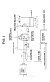
Fig. 1 illustrates the configuration of a laser-based
measuring apparatus (linear interferometer) for the most basic
two-wavelength type moving interferometer. A He-Ne laser, which
is a laser light source, applies a magnetic field to a discharger
to emit coherent light having two frequency components f1, f2,
which are slightly different in frequency, by the action of Zeeman
effect. The light beam components have planes of polarization
orthogonal to each other such that two circularly polarized light
beams are emitted in rotating directions opposite to each other.
The two frequency components f1, f2 are both stabilized. The light
beams are separated into two in the laser light source, and one
of the light beams is opto-electrically transduced directly by
a photodetector within the light source to output a beat signal
at f1-f2 as an electric reference signal, while the other light
beam having the components f1, f2 is output from the light source
and enters an interferometer.
The light beam entering the interferometer is separated
into two having the respective frequency components by a
polarization beam splitter. One of the light beams, f1 is emitted
to a measuring reflector attached to a moving object, such as
a corner cube prism, for example, and reflected thereby to become
measuring light. The other light beam f2 is reflected by a fixed
reference reflector to become reference light. The resulting
light beams are combined again by a polarization beam splitter,
i.e., interfere with each other. A relative movement between
the beam splitter and the measuring reflector causes the
frequency of the measuring light to change by Δf due to the
Doppler effect. In other words, with addition of a Doppler
component, the light component f1 changes to f1±Δf. Light beams,
which interfere with each other in the beam splitter, are
opto-electrically transduced by a photodetector, and a signal
to be measured f1-(f2±Δf) of a biased beat signal is generated
as the difference of optical frequency by heterodyne detection.
A measuring circuit only calculates ±Δf which is the difference
between the signal to be measured f1-f2±Δf and the reference signal
f1-f2 of the laser light source, and is converted to position
information. Specifically, a frequency counter in the measuring
circuit calculates a difference in count between the signal to
be measured and the reference signal. This difference is
multiplied by one half of the wavelength of the light beam to
derive a moving distance of the measuring reflector with respect
to the beam splitter.
Further, a technique for increasing the resolution of a
laser measuring apparatus is implemented in a two-pass
interferometer and a four-pass interferometer which pass the
measuring light through an optical path between a beam splitter
and a measuring reflector a plurality of times to increase a
Doppler component for increasing the resolution.
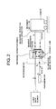
Fig. 2 illustrates the configuration of a two-pass
interferometer which optically improves the resolution of a
laser-based measuring apparatus.
The two-pass interferometer employs a polarization beam
splitter; a corner cube prism and a reference plane mirror
opposing each other with the polarization beam splitter and
optical axis interposed therebetween; and two quarter wavelength
plates positioned on the optical axis and between the
polarization beam splitter and corner cube prism. The plane
mirror is used as a measuring reflector.
Two light beams at frequencies f1, f2 having orthogonal
planes of polarization, emitted from a laser light source, are
separated by the polarization beam splitter. One of the light
beams having the component f1 is reflected by the polarization
beam splitter and bent by 90 degrees, passes through the quarter
wavelength plate, is reflected back by the fixed reference plane
mirror, and again passes through the quarter wavelength plate.
Therefore, since the plane of polarization of the reference light
rotates by 90 degrees, the reference light again travels via the
polarization beam splitter to the corner cube prism. The
reference light folded back by the corner cube prism goes to the
beam splitter, and is reflected again by the reference plane
mirror. In this event, since the reference light passes through
the quarter wavelength plate twice, the reference light is
reflected and bent by the beam splitter at the second time, and
returns toward the light source and impinges on a photodetector.
The other light beam having the component f2 goes to the
beam splitter from the laser light source, and is reflected by
the plane mirror functioning, and returns to the beam splitter
as the measuring reflector. At this time, since the measuring
light has passed through the quarter wavelength plate twice, the
measuring light is reflected and bent by the beam splitter at
the second time to reach the corner cube prism, folded back by
the corner cube prism, and bent by the beam splitter, so that
the measuring light again directs to the plane mirror which
functions as the measuring reflector. The measuring light
reflected by the plane mirror functioning as the measuring
reflector and returning to the beam splitter, travels via the
beam splitter, and returns to the light source, and impinges on
the photodetector at this time, since its plane of polarization
has rotated.
Therefore, the measuring light reciprocates twice between
the interferometer and the measuring reflector to generate the
Doppler component ±2Δf, so that the resolution is increased twice
as high as that of the linear interferometer.
The four-pass interferometer has increased lengths of
optical paths for reference light and measuring light, twice as
long as those of the two-pass interferometer, so that the
four-pass interferometer comprises one each of additional beam
bender and corner cube prism for correspondingly increasing the
lengths of optical paths for the reference light and measuring
light. Since the measuring light reciprocates four times between
the interferometer and measuring reflector, the measurement
resolution is increased four times as high as that of the linear
interferometer.
The two-pass interferometer and four-pass interferometer,
which are techniques for increasing the resolution of laser
measuring apparatuses, is provided with optical paths for an
increased number of optics, and is configured to direct two or
four light beams perpendicularly to a measuring plane mirror,
a plane mirror having a relatively large diameter must be attached
to an object under measurement. Therefore, these
interferometers cannot be used when a small measuring reflective
plane is measured due to a limited space, or when a measuring
reflective plane is not plane, such as cylindrical, spherical
and the like.
OBJECT AND SUMMARY OF THE INVENTION
The present invention has been made in view of the foregoing
circumstance, and it is an object of the invention to provide
a laser measuring apparatus and method which are capable of
optically doubling the measurement resolution in a simple optical
configuration, irrespective of which types of interferometer and
reflector are used.
A laser-based measuring apparatus of the present invention
divides a light beam from a laser light source into at least two
light beams, passes the light beams through different optical
paths from each other, recombines the light beams, has the light
beams interfere with each other to generate interfered light,
opto-electrically transduces the interfered light to an optical
frequency, and measures the amount of travel of an object which
changes an optical path length of a portion of an optical path
based on the optical frequency. The measuring apparatus
comprises:
In one aspect of the laser-based measuring apparatus
according to the invention, said reflection planes comprise
reflectors mounted on the object.
In another aspect of the laser-based measuring apparatus
according to the invention, said object is a cylinder having an
axis of rotation orthogonal to said measuring axis, and said
reflection planes are side surfaces of said cylinder opposing
to each other on a diameter.
In a further aspect of the laser-based measuring apparatus
according to the invention, said measuring apparatus comprises
a plurality of said opposing incident optical systems.
A laser-based measuring method according to the invention
is used for measuring an amount of travel of an object which
changes an optical path length of a portion of an optical path
based on an optical frequency. The optical frequency is obtained
by dividing a light beam from a laser light source into at least
two light beams, passing the light beams through different
optical paths from each other, recombining the light beams,
having the light beams interfere with each other to generate
interfered light, and opto-electrically transducing the
interfered light to the optical frequency. The measuring method
comprises the steps of:
In one aspect of the laser-based measuring method according
to the invention, said reflection planes comprise reflectors
mounted on the object.
In another aspect of the laser-based measuring method
according to the invention, said object is a cylinder having an
axis of rotation orthogonal to said measuring axis, and said
reflection planes are side surfaces of said cylinder opposing
to each other on a diameter.
In a further aspect of the laser-based measuring apparatus
according to the invention, a plurality of opposing incident
optical systems are provided.
The displacement of object's movement is measured by the
interference of light reflected by the fixed reference reflector
with light reflected by the movable measuring reflector mounted
on the moving object in the conventional laser-based measuring
apparatus. In contrast, according to the invention, the
laser-based measuring apparatus eliminates a fixed reference
reflector, and arranges two reflectors or reflection planes in
a back-to-back relationship to each other on a measuring axis
of a moving object, such that the measuring apparatus directs
two light beams split by a polarization beam splitter of an
interferometer into the two reflectors from opposite directions,
and differentially measures a relative displacement from the
polarization beam splitter to the back-to-back arranged
reflector pair to double a detected displacement, thereby making
it possible to increase the measuring resolution twice as high
as the conventional configuration.
BRIEF DESCRIPTION OF THE DRAWINGS
Figs. 1 and 2 are schematic diagrams for explaining a
conventional laser-based measuring apparatus;
Fig. 3 is a schematic diagram for explaining a laser-based
measuring apparatus according to one embodiment of the present
invention; and
Figs. 4 through 10 are schematic diagrams for explaining
laser-based measuring apparatuses according to other embodiments
of the present invention.
DETAILED DESCRIPTION OF THE PREFERRED EMBODIMENTS
In the following, a laser-based measuring apparatus
according to one embodiment of the present invention will be
described with reference to the drawings.
Fig. 3 illustrates the configuration of a linear
interferometer to which a differential measurement is applied
in accordance with the laser-based measuring apparatus of the
embodiment. The laser-based measuring apparatus comprises a
linear interferometer and a laser light source LS e.g., He-Ne
laser. The linear interferometer comprises a polarization beam
splitter 3; an optical system made up of two reflectors 1, 2
positioned on a measuring axis A of an object B in a back-to-back
relationship to each other; and beam benders (45-degree
reflectors) 4, 5, 6 which are positioned such that two light beams
f1, f2 separated by the polarization beam splitter 3 are incident
on the two reflectors 1, 2 from opposite directions to each other.
The two light beams f1, f2 from the laser light source LS having
different frequency components are separated by the polarization
beam splitter 3. The two light beams f1, f2 incident on the
reflectors 1, 2 from the opposite directions experience a change
in frequency due to the Doppler effect, return along their
respective optical paths, and interfere with each other in the
polarization beam splitter 3. The interfering reflected light
is opto-electrically transduced by a photodetector 10, and a
signal to be measured f1-(f2±2Δf) of a biased beat signal is
generated by heterodyne detection. A measuring circuit 11
connected to the photodetector 10 calculates only ±2Δf which is
the difference between the signal to be measured f1-f2±2Δf and
a reference signal f1-f2 from a laser light source LS, and is
converted to position information. Thus, the Doppler components
of the light beam f1 reflected by the reflector 1 have the same
positive and negative frequency components as the Doppler
components of the light beam f2 reflected by the reflector 2, so
that the signal to be measured is expressed by f1-f2±2Δf.
Therefore, the linear interferometer of this embodiment has an
optical displacement sensitivity and a measuring resolution
twice as high as those of a conventional linear interferometer.
Stated another way, the linear interferometer configured
as described above uses two opposing measuring light beams on
a common axis, and differentially measures a relative
displacement from the polarization beam splitter 3 to the
reflector 1, and a relative displacement from the polarization
beam splitter 3 to the reflector 2. Then, since the moving
displacements of the object appear in the phase opposite, the
difference between the two relative displacements becomes twice
as much as the moving displacement of the object. This results
in the resolution twice as high. It should be noted that from
requirements to satisfy a condition of vertical reflection at
all time, the measuring reflector may be implemented by a corner
cube prism or a cat's eye which is a prism that forces reflected
light, even changing in orientation, to return in parallel with
incident light. The corner cube prism is a tetrahedral prism
in the shape of a regular hexahedron having corners cut obliquely.
The corner cube prism has an inclined reflecting surface, and
the property of returning light incident from the incline
correctly in the opposite direction irrespective of the incident
angle. The cat's eye is a combination of a convex lens and a
plane mirror to have a similar property to the corner cube prism.
The present invention can be widely applied irrespective
of the type of interferometer and the type and size of reflector
as long as measuring light can be directed opposite to a measuring
axis and reflected.
For example, Fig. 4 illustrates the configuration of a
single beam interferometer to which the present invention is
applied. The single beam interferometer adds two quarter
wavelength plates to a linear interferometer, and is configured
such that both measuring light beams pass along one axis,
respectively, near the center of the interferometer. When the
single beam interferometer is used, ongoing and returning light
beams pass along the same optical path, so that a measurement
can be made with a small reflector. Alternatively, the reflector
may be comprised of a cat's eye (a mirror 1A and a convex lens
1B) which converges measuring light by the lens 1B, as illustrated
in Fig. 5, in which case the reflection plane is not limited to
be planar but measurements can be made even with a cylindrical
surface, a spherical surface, and the like, so that the resulting
single beam interferometer has wider applications. With the
corner cube prism, the reflection plane is positioned at the
center of the corner cube prism.
Two light beams f1, f2 having different frequency components
entering the interferometer from a laser light source LS are
separated by a polarization beam splitter 3. One of the light
beams, f1 goes to the polarization beam splitter 3, and is
reflected by a reflector 1 to return back to the polarization
beam splitter 3. Meanwhile, the light beam f1 passes through a
quarter wavelength plate 13 twice, so that the returning light
beam is bent by the polarization beam splitter 3 by 90 degrees
and enters a photodetector 10. The other light beam f2 is first
bent by the polarization beam splitter 3, led to a reflector 2
on the opposite side by three beam benders 4, 5, 6, and reflected
by the reflector 2, and subsequently returns along the same
optical path, so that the light beam f2 passes through a quarter
wavelength plate 14 twice. Thus, the returning light beam
travels through the polarization beam splitter 3 and enters the
photodetector 10. Consequently, the single beam interferometer
of this embodiment provides the displacement sensitivity and
resolution twice as high as conventional linear interferometer
and single beam interferometer.
It is further possible to enhance, for example, the
resolution of a two-pass interferometer four times as high as
a conventional linear interferometer, enhance the resolution of
a four-pass interferometer eight times as high as a conventional
linear interferometer, and the like.
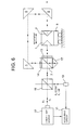
Fig. 6 illustrates the configuration of a single beam
two-pass interferometer, modified from the single beam
interferometer of Fig. 4, for making a differential measurement.
Two light beams f1, f2 having different components, emitted from
a laser light source LS, pass through a non-polarization beam
splitter 16, and are separated by a polarization beam splitter
3 of the interferometer. The light beam f1 passing straight
through the polarization beam splitter 3 is reflected back by
a measuring reflector 1. In this event, the light f1 passes
through a quarter wavelength plate 13 twice and therefore has
the plane of polarization rotated by 90 degrees, so that the light
beam f1 is bent at this time by the polarization beam splitter
3 toward a corner cube prism 17, and further returns the same
path and again impinges on the measuring reflector 1. Since the
light reflected back to the polarization beam splitter 3 has the
plane of polarization rotated further by 90 degrees, the light
travels in the polarization beam splitter 3, at this time, to
return to the laser light source LS. A portion of the returning
light is separated by the non-polarization beam splitter 16 and
incident on a photodetector 10.
The light beam f2 first bent by the polarization beam
splitter 3 by 90 degrees reciprocates twice between the
interferometer and a measuring reflector 2. Specifically, the
light beam f2 led to the reflector 2 on the opposite side by three
beam bender 4, 5, 6 is reflected by the reflector 2, subsequently
returns along the same optical path, and passes through a quarter
wavelength plate 14 twice, so that the returning light goes via
the polarization beam splitter 3 to the corner cube prism 17,
and then returns along the same path and again impinges on the
measuring reflector 2, is reflected by the measuring reflector
2 to return again to the polarization beam splitter 3. Since
the resulting light has the plane of polarization rotated further
by 90 degrees, the light is bent by the polarization beam splitter
3 at this time and returns to the laser light source LS. A portion
of the returning light is separated by the non-polarization beam
splitter 16, and incident on the photodetector 10. This
configuration provides the resolution four times as high as a
single beam interferometer in a basic configuration.
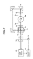
Fig. 7 illustrates a further exemplary modification for
measuring run-out of the axis of rotation, to which the
differential single beam two-pass interferometer is applied.
Members indicated by the same reference numerals in Figs. 7 and
6 are identical. In this exemplary modification, a measuring
reflector is applied to columnar reflection planes 1a, 2a instead
a measuring reflector is applied to columnar reflection planes
1a, 2a instead of an object B as a cylindrical rotor RB. The
reflection planes 1a, 2a are side surfaces, arranged back-to-back
to each other, of the rotor, the diameter of which is positioned
on a measuring axis. The measuring axis is oriented to pass
through the axis of rotation of the rotor. This interferometer
is also configured such that both measuring light beams are
co-axial near the center of the interferometer. Similar to the
cat's eye configuration, the reflection planes have one point,
respectively, so that converging lenses 21, 22 are co-axially
positioned on either side of the rotor RB on the measuring axis
for converging the measuring light. Also, this exemplary
modification can measure a displacement of run-out of the axis
of rotation of the rotor with the same optical paths and resolution
as those described in connection with Fig. 6 (the reflectors 1,
2 are read for reflection planes 1a, 2a, respectively).
A component not synchronized with the rotation (non-repeatable
component) extracted from the displacement of run-out
of the axis of rotation of the rotor measured by the laser-based
measuring apparatus is NRRO (Non Repetitive Run Out). NRRO is
one of factors critical to the rotation accuracy of a spindle,
and is a cause of deteriorating the recording position accuracy
of an optical disk and a magnetic disk. Conventionally, NRRO
of a spindle has been difficult to measure with a resolution
equivalent to a four-pass interferometer. However, the
measurement of NRRO becomes possible when using a method which
applies the differential single beam two-pass interferometer as
Fig. 8 further illustrates the configuration of the
differential single beam two-pass interferometer illustrated in
Fig. 7 which is applied to a measurement of run-out of axes of
rotation of two orthogonal XY measuring axes. Likewise, this
exemplary modification is capable of measuring a displacement
of run-out of the axis of rotation of a rotor on each of the X-,
Y-axes with the same optical paths and resolution as those
described in connection with Fig. 6 (the reflectors 1, 2 are read
for reflection planes 1a, 2a and 1b, 2b) by reflected light from
the reflection planes 1a, 2a and 1b, 2b existing on common axes
of the rotor RB. In this manner, a two-dimensional measurement
of NRRO can be accomplished with a resolution equivalent to that
of the conventional four-pass interferometer. A displacement
of run-out of the axis of rotation in the X-axis direction
illustrated in Fig. 8 is measured by an optical path comprising
a non-polarization beam splitter 16, a polarization beam splitter
3, quarter wavelength plates 13, 14, beam benders 4, 5, 6,
converging lenses 21, 22, and a photodetector 10, while a
displacement of run-out of the axis of rotation in the Y-axis
direction is measured by an optical path comprising a non-polarization
beam splitter 16a, a relay beam bender 26, a
polarization beam splitter 3a, quarter wavelength plates 13a,
14a, beam benders 4a, 5a, 6a, converging lenses 21a, 22a, and
a photodetector 10a. An optical beam is supplied to the optical
path of each axis by a non-polarization beam splitter 25 which
splits a light beam from a laser light source LS to the X- and
Y-axes.
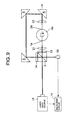
Fig. 9 illustrates the configuration of a single beam
one-pass interferometer which is a modification to the single
beam interferometer illustrated in Fig. 4 for making a
differential measurement. Members indicated by the same
reference numerals in Figs. 9 and 4 are identical. This exemplary
modification applies measuring reflectors to columnar reflection
planes 1a, 2a as a cylindrical rotor RB in place of the object
B. The reflection planes 1a, 2a are side portions, arranged
back-to-back to each other, of a rotor, the diameter of which
is positioned on a measuring axis. The measuring axis is
positioned to pass the axis of rotation of the rotor. This
interferometer is also configured such that both measuring light
beams are co-axial near the center of the interferometer. Since
the reflection planes have one point, respectively, so that
converging lenses 21, 22 are co-axially positioned on either side
of the rotor RB on the measuring axis for converging the measuring
light. Also, this exemplary modification is capable of measuring
a displacement of run-out of the axis of rotation of the rotor
with the same optical paths and resolution as those described
in connection with Fig. 4 (the reflectors 1, 2 are read for
reflection planes 1a, 2a).
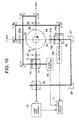
Fig. 10 illustrates the configuration of another one-pass
configuration applied to a measurement of run-out of the axis
of rotation, specifically, an application of the rotation run-out
measurement illustrated in Fig. 9 to an orthogonal XY biaxial
measurement. Likewise, this exemplary modification is capable
of measuring a displacement of run-out of the axis of rotation
of a rotor on each of the X-, Y-axes with the same optical paths
and resolution as those described in connection with Fig. 4 (the
reflectors 1, 2 are read for reflection planes 1a, 2a and 1b,
2b) by reflected light from the reflection planes 1a, 2a and 1b,
2b existing on the common axes of the rotor RB. A displacement
of run-out of the axis of rotation in the X-axis direction
illustrated in Fig. 10 is measured by an optical path comprising
a polarization beam splitter 3, quarter wavelength plates 13,
14, beam benders 4, 5, 6, converging lenses 21, 22, and a
photodetector 10, while a displacement of run-out of the axis
of rotation in the Y-axis direction is measured by an optical
path comprising relay beam benders 26, 27, a polarization beam
splitter 3a, quarter wavelength plates 13a, 14a, beam benders
4a, 5a, 6a, converging lenses 21a, 22a, and a photodetector 10a.
An optical beam is supplied to the optical path of each axis by
a non-polarization beam splitter 25 which splits a light beam
from a laser light source LS to the X- and Y-axes.
In the present invention, two reflectors or reflection
planes are arranged back-to-back to each other on a measuring
axis of an object, and are irradiated with measuring light from
the opposite directions with respect to the measuring axis to
differentially measure displacements in opposite phases to each
other, so that the present invention can be applied irrespective
to the type of interferometer. Also, since the present invention
can be applied to a measurement of a small measuring reflection
plane due to a limited space, and to a single beam interferometer
for use with a measuring reflection plane other than plane mirror,
for use with a measuring reflection plane other than plane mirror,
such as a cylindrical plane, a spherical plane, and the like,
measurements can be accomplished with a resolution maximally four
times as high as a linear interferometer in these applications
as well.
It is understood that the foregoing description and
accompanying drawings set forth the preferred embodiments of the
invention at the present time. Various modifications, additions
and alternative designs will, of course, become apparent to those
skilled in the art in light of the foregoing teachings without
departing from the spirit and scope of the disclosed invention.
Thus, it should be appreciated that the invention is not limited
to the disclosed embodiments but may be practiced within the full
scope of the appended claims.