EP1225380B1 - Flow control valve - Google Patents
Flow control valve Download PDFInfo
- Publication number
- EP1225380B1 EP1225380B1 EP00944367A EP00944367A EP1225380B1 EP 1225380 B1 EP1225380 B1 EP 1225380B1 EP 00944367 A EP00944367 A EP 00944367A EP 00944367 A EP00944367 A EP 00944367A EP 1225380 B1 EP1225380 B1 EP 1225380B1
- Authority
- EP
- European Patent Office
- Prior art keywords
- pressure contact
- contact portion
- valve body
- supporting plates
- flow control
- Prior art date
- Legal status (The legal status is an assumption and is not a legal conclusion. Google has not performed a legal analysis and makes no representation as to the accuracy of the status listed.)
- Expired - Lifetime
Links
- 238000012856 packing Methods 0.000 claims description 21
- 239000012530 fluid Substances 0.000 claims 2
- 239000013013 elastic material Substances 0.000 claims 1
- 230000036772 blood pressure Effects 0.000 description 11
- 230000002093 peripheral effect Effects 0.000 description 7
- BGPVFRJUHWVFKM-UHFFFAOYSA-N N1=C2C=CC=CC2=[N+]([O-])C1(CC1)CCC21N=C1C=CC=CC1=[N+]2[O-] Chemical compound N1=C2C=CC=CC2=[N+]([O-])C1(CC1)CCC21N=C1C=CC=CC1=[N+]2[O-] BGPVFRJUHWVFKM-UHFFFAOYSA-N 0.000 description 3
- 238000005259 measurement Methods 0.000 description 3
- 238000007599 discharging Methods 0.000 description 2
- 238000006073 displacement reaction Methods 0.000 description 1
- 239000004033 plastic Substances 0.000 description 1
Images



Classifications
-
- F—MECHANICAL ENGINEERING; LIGHTING; HEATING; WEAPONS; BLASTING
- F16—ENGINEERING ELEMENTS AND UNITS; GENERAL MEASURES FOR PRODUCING AND MAINTAINING EFFECTIVE FUNCTIONING OF MACHINES OR INSTALLATIONS; THERMAL INSULATION IN GENERAL
- F16K—VALVES; TAPS; COCKS; ACTUATING-FLOATS; DEVICES FOR VENTING OR AERATING
- F16K31/00—Actuating devices; Operating means; Releasing devices
- F16K31/02—Actuating devices; Operating means; Releasing devices electric; magnetic
- F16K31/06—Actuating devices; Operating means; Releasing devices electric; magnetic using a magnet, e.g. diaphragm valves, cutting off by means of a liquid
-
- F—MECHANICAL ENGINEERING; LIGHTING; HEATING; WEAPONS; BLASTING
- F16—ENGINEERING ELEMENTS AND UNITS; GENERAL MEASURES FOR PRODUCING AND MAINTAINING EFFECTIVE FUNCTIONING OF MACHINES OR INSTALLATIONS; THERMAL INSULATION IN GENERAL
- F16K—VALVES; TAPS; COCKS; ACTUATING-FLOATS; DEVICES FOR VENTING OR AERATING
- F16K7/00—Diaphragm valves or cut-off apparatus, e.g. with a member deformed, but not moved bodily, to close the passage ; Pinch valves
- F16K7/12—Diaphragm valves or cut-off apparatus, e.g. with a member deformed, but not moved bodily, to close the passage ; Pinch valves with flat, dished, or bowl-shaped diaphragm
- F16K7/14—Diaphragm valves or cut-off apparatus, e.g. with a member deformed, but not moved bodily, to close the passage ; Pinch valves with flat, dished, or bowl-shaped diaphragm arranged to be deformed against a flat seat
Definitions
- the present invention relates to an electromagnetic valve for a flow control which is used as a constant speed air release valve for a blood pressure valve or the like, and particularly to a flow control valve which has a simple structure and can gradually increase an air volume displacement.
- a blood pressure gauge structured such as to feed an air to a cuff wound around an arm of a person under measurement of blood pressure by a pump, increase a pressure within the cuff to a predetermined value, thereafter gradually reduce the pressure and measure the blood pressure in a pressure reducing step.
- the structure is made such as to reduce the pressure within the cuff after measuring the blood pressure so as to release a feeling of pressure applied to the arm of the person under measurement of blood pressure, and take out the cuff from the arm.
- the flow control valve is constituted by an air outflow port communicated with the cuff, a packing closing the outflow port and mounted to a front end of a movable shaft, and a solenoid driving the movable shaft in an axial direction.
- the flow control valve described in the publication mentioned above is structured such that the air outflow port and respective end surfaces of the packing are formed in a flat surface having no parallel relation to each other, and the air outflow port is opened not all at once but step by step by gradually moving the packing apart from the air outflow port.
- the structure is made such as to cut an electric current of a solenoid so as to press down the movable shaft by a spring after the measurement of the blood pressure is finished by reducing the pressure within the cuff to a predetermined value, thereby quickly reducing the pressure within the cuff to an atmospheric pressure.
- the flow control valve described in the publication mentioned above is structured such that any one of an end surface of the air outflow port or an end surface of the packing is slightly inclined with respect to a moving direction of a sliding shaft, however, an outflow amount of air is affected by an attitude of the packing. Accordingly, it is necessary to precisely adjust an angle of incline of the air outflow port and the respective end surfaces of the packing, and it is necessary to adjust so that the attitude of the movable shaft smoothly moves without changing.
- Valves of this type are known from the documents US 4790346 , JP 54153019 U, EP 0486945 , US 5265841 and JP 54117940 .
- an object of the present invention is to provide a flow amount control valve structured such as to gradually increase an air outflow amount while having a simple structure.
- an object of the present invention is to provide a flow control valve which can achieve a cost cutting by reducing a number of parts.
- an object of the present invention is to provide a flow control valve which can control a little amount discharge.
- a flow control valve in accordance with the present invention is defined by claim 1. It is preferable that a width of the supporting plate is set to be substantially the same as an outer diameter of the pressure contact portion.
- the structure may be formed so as to shift a center of the outflow port from a center of the pressure contact portion in the valve body.
- the outflow port may be formed so as to be shifted from an axis of a connection pipe communicated with the cuff, or one of the supporting plates in the valve body may be formed shorter than another so as to be shifted from the center of the pressure contact portion.
- the structure may be formed so as to make a thickness of one of the supporting plates in the valve body smaller than that of another, or fit and insert the core at a position shifted from the center of the cylindrical packing, thereby making a spring action of one of the supporting plates smaller than that of another.
- the discharge air is brought into contact with the position shifted from the center of the pressure contact portion, so that the flat surface of the pressure contact portion is inclined. Further, if one of the supporting plates of the valve body is formed shorter than another, the outflow port is shifted from the center of the pressure contact portion, and a difference is generated in the spring action of the supporting plates, so that the flat surface of the pressure contact portion is inclined by the discharge air.
- the spring action of one supporting plate becomes weaker than the spring action of another supporting plate, so that the flat surface of the pressure contact portion in the valve body tends to be inclined by the discharge air from the outflow port.
- grooves or slits may be formed in the supporting plates of the valve body.
- the spring action of the supporting plates becomes small, and it is possible to restrict a back action even in the case that a pressure of the discharge air from the outflow port becomes small. Accordingly, it is possible to maintain the incline of the flat surface of the pressure contact portion in the valve body for a long time, and it is possible to further precisely control the discharge air.
- the grooves or the slits formed in the supporting plates in the valve body may be symmetrically or asymmetrically formed in both sides of the pressure contact portion.
- a shape of the groove or the slit is not particularly limited, may be formed in a circular arc shape, may be formed in a right angle direction with respect to side surfaces of the supporting plates, or may be formed in an oblique direction with respect to the side surfaces of the supporting plates.
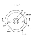
- Fig. 1 is a plan view showing a flow control valve in accordance with a first embodiment of the present invention
- Fig. 2 is a cross sectional view along a line A-A in Fig. 1
- Fig. 3 is a plan view of a valve body
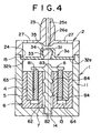
- Fig. 4 is a cross sectional view showing a flow control valve in accordance with a second embodiment of the present invention
- Fig. 5 is a cross sectional view showing a valve body in a flow control valve in accordance with a third embodiment of the present invention
- Fig. 6 is a cross sectional view showing a valve body in a flow control valve in accordance with a fourth embodiment of the present invention
- Fig. 1 is a plan view showing a flow control valve in accordance with a first embodiment of the present invention
- Fig. 2 is a cross sectional view along a line A-A in Fig. 1
- Fig. 3 is a plan view of a valve body
- Fig. 4 is a cross sectional view
- FIG. 7 is a plan view showing a valve body in a flow control valve in accordance with a fifth embodiment
- Fig. 8 is a cross sectional view along a line B-B in Fig. 7
- Fig. 9 is a plan view showing a valve body in a flow control valve in accordance with a sixth embodiment
- Fig. 10 is a plan view showing a valve body in a flow control valve in accordance with a seventh embodiment
- Fig. 11 is a plan view showing a valve body in a flow control valve in accordance with an eighth embodiment
- Fig. 12 is a plan view showing a valve body in a flow control valve in accordance with a ninth embodiment
- FIG. 13 is a plan view showing a valve body in a flow control valve in accordance with a tenth embodiment
- Fig. 14 is a cross sectional view showing a closing state of an outflow port by the valve body
- Fig. 15 is a schematic view showing a relation between the outflow port and a pressure contact portion of the valve body.
- FIGs. 1 to 3 show a first embodiment of a preferable flow control valve in accordance with the present invention.
- a whole structure of the flow control valve is made such that both end portions of a valve body 3 formed in a substantially rectangular shape in a plan view are held between a cylindrical casing 1 and a lid body 2, and a cylindrical receiving body 6 for receiving a solenoid 4 and a magnet 5 is arranged within a casing 1.
- the structure is made by movably fitting and inserting a valve operating body 8 pressing up the valve body 3 to a through hole 7 of the receiving body 6.
- cut-off flat surfaces 12 and 12 are provided in side surfaces of a peripheral wall 11 of the cylindrical casing 1 in parallel so as to oppose to each other.
- a through hole 14 inserting and passing an end portion of the valve operating body 8 therethrough is provided in a center of a bottom portion 13 in the casing 1, and a step portion 15 is formed in an inner side of an upper opening portion.
- the lid body 2 is constituted by an upper plate 21 and a peripheral wall 22, and a connection pipe 23 communicated with a cuff is protruded from a center portion of an upper plate 21 in a moving direction of the valve operating body 8.
- a convex portion 24 fitted to the step portion 15 is provided in an inner side of a lower end in the peripheral wall 22.
- An outflow pot 26 of an outflow passage provided in the connection pipe 23 protrudes from a lower surface of the upper plate 21.
- Discharge ports 27 and 27 are provided in the upper plate 21 at positions at an angle of 180 degrees with respect to the connection pipe 23, and cut-off flat surfaces 28 are provided in the side surfaces of the peripheral wall 22 in parallel so as to oppose to each other.
- the flat surfaces 28 are formed so as to coincide with the flat surfaces 12 of the casing 1 at a time of being assembled with the casing 1.
- connection pipe 23 and an axis of the valve operating body 8 are substantially the same, however, a center of the outflow passage 25 is formed so as to be shifted from a center of the connection pipe 23, and it is preferable to set a shifting direction to a longitudinal direction of the valve body 3 mentioned below.
- the valve body 3 is structured, as shown in Fig. 3 , such that supporting plates 32 and 32 are provided in a lower end portion of a substantially cylindrical pressure contact portion 31 in a right angle direction with respect to a side surface of the pressure contact portion 31 at an angle of 180 degrees.
- the pressure contact portion 31 is formed by fitting and inserting a core 34 from an opening of a bottom portion in a cylindrical packing 33.
- the supporting plates 32 and the cylindrical packing 33 are integrally formed by an elastic member such as a rubber, a plastic or the like.
- the supporting plates 32 and 32 have substantially the same thickness, and it is preferable to set a width thereof to be substantially the same size as an outer diameter of the pressure contact portion. End portions of the supporting plates 32 and 32 are gripped with respect to the peripheral wall 22 of the lid body 2 in a state of being bridged over the step portion of the upper opening portion in the cylindrical casing 1.
- An axis of the pressure contact portion and an axis of the connection pipe 23 exist on substantially the same line.
- a surface 35 being in pressure contact with the outflow port 26 in the cylindrical packing 33 is formed in a flat surface 35, and is arranged substantially in parallel to the outflow port 26.
- the supporting plates 32 and 32 are formed by the elastic member as mentioned above, the supporting plates 32 and 32 extends so as to pressure contact the flat surface 35 of the cylindrical packing 33 with the outflow port 26 and close the outflow port 26 when the core 34 is pressed up from a lower portion in Fig. 2 .
- the axis of the pressure contact portion 31 and the axis of the connection pipe 23 exist on substantially the same line, however, since the outflow passage 25 is formed so as to be shifted from the axis of the connection pipe 23, the outflow port 26 is in pressure contact with the position shifted from the axis of the cylindrical packing 33.
- the cylindrical receiving body 6 has a double structure constituted by an inner wall 62 and an outer wall 63, an inner side of the inner wall 62 is constituted by the through hole 7 extending therethrough in an axial direction, and a portion between the inner wall 62 and the outer wall 63 is constituted by an annular groove 64.
- the solenoid 4 and the magnet 5 are received in the annular groove 64.
- the valve operating body 8 is formed by a flange portion 81 slightly extending in a diametrical direction from the solenoid 4, and a sliding shaft 82.
- a hemispheric convex portion 83 is provided on an axis of the sliding shaft 82 in a protruding manner, in a center portion of an upper surface in the flange portion 81.
- An annular convex portion 84 preventing a play from being generated with respect to the through hole 7 is provided on an outer peripheral surface of the sliding shaft 82.
- Fig. 4 shows a second embodiment in accordance with the present invention.
- This embodiment is characterized in that the center of the valve body is formed so as to be shifted from the centers of the outflow port in the connection pipe and the convex portion in the valve operating body. That is, centers of an outflow port 26a of an outflow passage 25a provided in the center of the connection pipe 23 and the convex portion 83 of the valve operating body 8 are provided on the same line in a vertical direction. At this time, it is preferable that axes of the outflow passage 25a and the sliding shaft 82 are provided on substantially the same line as the centers of the outflow port 26a and the convex portion 83.
- the center of the pressure contact portion 31 constituting the valve body 3a is provided so as to be shifted from the centers of the outflow port 26a and the convex portion 83.
- a shifting direction of the center of the pressure contact portion 31 is any one side of the supporting plates 32 formed in both sides of the pressure contact portion 31 at an angle of 180 degrees.
- a supporting plate 32b is formed short, and a supporting plate 32a is formed long. Accordingly, the supporting plate in the direction in which the pressure contact portion 31 is shifted is formed short, and the supporting plate in the opposite side is formed long.
- a right side is formed long and a left side is formed short.
- the structures other than the valve body 3a and the outflow port 26a are the same as the structures of the first embodiment, the same reference numerals are attached to the same structures, and a description thereof will be omitted.
- Fig. 5 is a cross sectional view showing only a valve body of a flow amount control valve in accordance with a third embodiment of the present invention. Since the other structures are the same as those in Fig. 4 , a description of a whole will be omitted.
- This embodiment is characterized in that one of the supporting plates constituting the valve body is formed so as to be thin. That is, in the same manner as that of the second embodiment, the structure is made such that supporting plates 32c and 32d made of an elastic member such as a rubber or the like are provided in the lower end portion of the substantially cylindrical pressure contact portion 31 at an angle of 180 degrees in a right angle direction with respect to the side surface of the pressure contact portion 31.
- a thickness tl of the supporting plate 32d is made smaller than a thickness t of the supporting plate 32c, thereby reducing the spring action.
- the center of the pressure contact portion 31 in accordance with the third embodiment is arranged on substantially the same line as that of the centers of the outflow port 26a and the convex portion 83.
- Fig. 6 is a cross sectional view showing only a valve body of a flow amount control valve in accordance with a fourth embodiment of the present invention. Since the other structures are the same as those in Fig. 4 , a description of a whole will be omitted.
- This embodiment is structured such that a core 34a of a pressure contact portion 31a is shifted to a side of one of the supporting plates, thereby reducing the spring action of another supporting plate. That is, in the same manner as that of the first to third embodiments, the structure is made such that supporting plates 32 and 32 made of an elastic member such as a rubber or the like are provided in the lower end portion of the substantially cylindrical pressure contact portion 31a at an angle of 180 degrees in a horizontal direction.
- the pressure contact portion 31a is formed by fitting and inserting the core 34a to the cylindrical packing 33a in which a bottom portion is open.
- a peripheral wall of the cylindrical packing 33a is structured such that a side of one of the supporting plates is formed so as to be thick, and a side of another is formed so as to be thin, and the center of the bottom opening is shifted. Accordingly, the spring action of one of the supporting plates becomes small by fitting and inserting the core 34a.
- the flat surface 35 of the pressure contact portion 31 or 31a is inclined by the air discharged through the outflow passage 25 so as to have a non-parallel relation to the lower end surface of the outflow port 31, because the structure is made such that the spring action of one of the supporting plates is small. Since the flat surface 35 gradually moves apart from the outflow port 26 in the state in which the flat surface 35 is inclined, it is possible to discharge the air at a small speed.
- Figs. 7 and 8 are a plan view and a cross sectional view showing only a valve body 3d of a flow amount control valve in accordance with a fifth embodiment of the present invention.
- the same reference numerals are attached to the same structures as those of the embodiments mentioned above, and a description thereof will be omitted.
- the spring action of one of the supporting plates is made smaller than that of another by forming grooves or slits in the supporting plates 32.
- the structure is made such that supporting plates 32 and 32 made of an elastic member such as a rubber or the like are provided in the lower end portion of the substantially cylindrical pressure contact portion 31 at an angle of 180 degrees in a horizontal direction.
- the pressure contact portion 31 is formed by fitting and inserting the core 34 to the cylindrical packing 33 in which a bottom portion is open.
- Circular arc-shaped grooves 37 and 37a are provided on upper surfaces of the supporting plates 32 and 32.
- the circular arc shaped grooves 37 and 37a are provided in upper and lower portions of a center line X in a direction of the supporting plates 32 and 32 so as to be symmetric with respect to a point.
- a relation L > L1 or L ⁇ L1 is established.
- Fig. 9 is a plan view showing only a valve body 3e of a flow control valve in accordance with a sixth embodiment of the present invention.
- This embodiment is structured such that a position of the groove is different from that of the fifth embodiment shown in Fig. 7 . That is, grooves 38 and 38a provided on the upper surface of the supporting plates 32 are provided on the center line X in the direction of the supporting plates 32 and 32.
- a relation between L and T is the same as that of the embodiment shown in Fig. 7 . Accordingly, a detailed description thereof will be omitted.
- Fig. 10 is a plan view showing only a valve body 3f of a flow control valve in accordance with a seventh embodiment of the present invention.
- This embodiment is structured such that grooves 39 and 39a are provided in a symmetrical manner so as to be separated into both sides of the center line X in the direction of the supporting plates 32 and 32.
- a relation between gaps and widths of the grooves 39 and 39a from the pressure contact portion 31 is the same as that of the case of the fifth embodiment and the sixth embodiment mentioned above. Accordingly, a detailed description thereof will be omitted.
- Fig. 11 is a plan view showing only a valve body 3g of a flow control valve in accordance with an eighth embodiment of the present invention.
- This embodiment is different from the embodiments mentioned above in a point that grooves 40 and 40a are provided in a dotted line shape.
- a relation between gaps and widths of the grooves 40 and 40a from the pressure contact portion 31 is the same as that of the case of the fifth embodiment and the sixth embodiment mentioned above. Accordingly, a detailed description thereof will be omitted.
- Fig. 12 is a plan view showing only a valve body 3h of a flow control valve in accordance with a ninth embodiment of the present invention.
- This embodiment is different in a point that grooves 41 and 41a are asymmetrically provided in both sides of the center line X of the supporting plates 32 and 32a. That is, the structure is made such that a length of the groove 41 is longer than that of the groove 41a. Gaps and widths of the grooves 41 and 41a from the pressure contact portion 31 are the same, however, the spring action of one of the supporting plates is made small by giving a difference to their lengths.
- Fig. 13 is a plan view showing only a valve body 3i of a flow control valve in accordance with a tenth embodiment of the present invention.
- This embodiment is different in a point that grooves 42 and 42a are provided in a right angle direction with respect to the side surfaces of the supporting plates 32 and 32.
- a relation between gaps and widths of the grooves 42 and 42a from the pressure contact portion 31 is the same as that of the case of the fifth embodiment and the sixth embodiment mentioned above. Accordingly, a detailed description thereof will be omitted.
- the grooves in each of the embodiments can be changed to slits.
- the spring action of one of the supporting plates small by giving a difference to a gap from the pressure contact portion 31 and/or a length of the slit, in the slits of any one of the supporting plates 32 and 32.
- the grooves or the slits shown in the embodiments on and after Fig. 7 can be realized by combining with the first to fourth embodiments shown before Fig. 6 .
- the grooves or the slits may be formed in symmetrical.
- a predetermined electric current is applied to the solenoid 4 so as to generate an electromagnetic force, thereby moving the valve operating body 8 to an upper portion in Fig. 14 .
- the convex portion 83 is brought into contact with the core 34 of the valve body 3 so as to press up the valve body 3 against the spring action of the supporting plates 32 and 32, thereby pressure contacting the flat surface 35 of the cylindrical packing 33 with the outflow port 26 so as to completely close.
- the valve operating body 8 Since the electromagnetic force breaks down in correspondence to the reduction of electric current, the valve operating body 8 is gradually pressed down to the lower portion in Fig. 14 by the spring action of the supporting plates 32 and 32. The valve operating body 8 is pressed down, whereby the outflow port 26 is gradually opened, however, since the outflow port 26 is shifted from the center of the pressure contact portion 31, and the convex portion 83 is brought into contact with the center of the pressure contact portion 31, the flat surface 35 is slightly inclined by the discharge air. It is possible to precisely control the discharge air due to the incline.
- Fig. 15(a) shows a moment at which the pressure contact portion 31 is going to open the outflow port 26, and Fig. 15(b) shows a matter that the flat surface 35 of the pressure contact portion 31 is inclined and the air is gradually discharged from the right side in the drawing.
- the valve operating body 8 is pressed down due to the spring action of the supporting plates by gradually breaking down the electromagnetic force of the solenoid 4, and the closed air is gradually discharged.
- the outflow port is quickly opened due to the spring action of the supporting plates 32 and 32, whereby it is possible to quickly reduce the pressure within the cuff to the atmospheric pressure.
- the flow control valves on and after the second embodiment are also operated in the same manner as that of the first embodiment mentioned above, and show the air discharge property in which the air discharge amount is gradually increased. A detailed description thereof will be omitted. Further, when combining the first to fourth embodiments with the embodiments on and after the fifth embodiment, it is possible to restrict the back action so as to maintain the incline of the pressure contact portion long.
- the flow control valve in accordance with the present invention is structured such that the outflow port and the flat surface of the pressure contact portion closing the outflow port are formed in parallel to each other, it is possible to close by a little pressing force.
- the structure is made such as to incline the flat surface of the pressure contact portion due to the discharge air from the outflow port. Accordingly, the outflow port is gradually opened in correspondence to the movement of the pressure contact portion, and it is possible to precisely and continuously control the discharge air amount.
- the supporting plates of the valve body have the spring action, it is possible to incline the flat surface of the pressure contact portion due to the discharge air from the outflow port, and it is possible to move the valve operating body, so that the coil spring for moving the valve operating body used in the conventional art is not required. Accordingly, it is possible to reduce the number of the parts as a whole, and it is possible to achieve a cost cutting. Further, in the case of applying the flow control valve in accordance with the present invention to the blood pressure gauge, it is possible to precisely control the discharge air flow amount.
Landscapes
- Engineering & Computer Science (AREA)
- General Engineering & Computer Science (AREA)
- Mechanical Engineering (AREA)
- Magnetically Actuated Valves (AREA)
- Lift Valve (AREA)
- Multiple-Way Valves (AREA)
- Check Valves (AREA)
- Measuring Pulse, Heart Rate, Blood Pressure Or Blood Flow (AREA)
Description
- The present invention relates to an electromagnetic valve for a flow control which is used as a constant speed air release valve for a blood pressure valve or the like, and particularly to a flow control valve which has a simple structure and can gradually increase an air volume displacement.
- Various kinds of blood pressure gauges are proposed, however, there is a blood pressure gauge structured such as to feed an air to a cuff wound around an arm of a person under measurement of blood pressure by a pump, increase a pressure within the cuff to a predetermined value, thereafter gradually reduce the pressure and measure the blood pressure in a pressure reducing step. The structure is made such as to reduce the pressure within the cuff after measuring the blood pressure so as to release a feeling of pressure applied to the arm of the person under measurement of blood pressure, and take out the cuff from the arm.
- In the flow control valve of the blood pressure gauge mentioned above, it is important to gradually reduce the pressure within the pressurized cuff, and accordingly it is necessary to gradually increase a size of a pressure outflow port communicated with the cuff. A representative flow control valve as mentioned above is described in Japanese Unexamined Patent Publication No.
6-47007 - The flow control valve described in the publication mentioned above is structured such that the air outflow port and respective end surfaces of the packing are formed in a flat surface having no parallel relation to each other, and the air outflow port is opened not all at once but step by step by gradually moving the packing apart from the air outflow port. The structure is made such as to cut an electric current of a solenoid so as to press down the movable shaft by a spring after the measurement of the blood pressure is finished by reducing the pressure within the cuff to a predetermined value, thereby quickly reducing the pressure within the cuff to an atmospheric pressure.
- However, the flow control valve described in the publication mentioned above is structured such that any one of an end surface of the air outflow port or an end surface of the packing is slightly inclined with respect to a moving direction of a sliding shaft, however, an outflow amount of air is affected by an attitude of the packing. Accordingly, it is necessary to precisely adjust an angle of incline of the air outflow port and the respective end surfaces of the packing, and it is necessary to adjust so that the attitude of the movable shaft smoothly moves without changing.
- Valves of this type are known from the documents
US 4790346 ,JP 54153019 EP 0486945 ,US 5265841 andJP 54117940 - Accordingly, an object of the present invention is to provide a flow amount control valve structured such as to gradually increase an air outflow amount while having a simple structure.
- Further, an object of the present invention is to provide a flow control valve which can achieve a cost cutting by reducing a number of parts.
- Further, an object of the present invention is to provide a flow control valve which can control a little amount discharge.
- A flow control valve in accordance with the present invention is defined by
claim 1. It is preferable that a width of the supporting plate is set to be substantially the same as an outer diameter of the pressure contact portion. - At a time of discharging the air from the outflow port, in order to incline the flat surface of the pressure contact portion in the valve body by the discharge air from the outflow port, the structure may be formed so as to shift a center of the outflow port from a center of the pressure contact portion in the valve body. In order to shift the center of the outflow port from the center of the pressure contact in the valve body, for example, the outflow port may be formed so as to be shifted from an axis of a connection pipe communicated with the cuff, or one of the supporting plates in the valve body may be formed shorter than another so as to be shifted from the center of the pressure contact portion.
- Further, at a time of discharging the air from the outflow port, in order to incline the flat surface of the pressure contact portion in the valve body by the discharge air from the outflow port, the structure may be formed so as to make a thickness of one of the supporting plates in the valve body smaller than that of another, or fit and insert the core at a position shifted from the center of the cylindrical packing, thereby making a spring action of one of the supporting plates smaller than that of another.
- In the case of forming the outflow port so as to shift from the axis of the connection pipe communicated with the cuff, the discharge air is brought into contact with the position shifted from the center of the pressure contact portion, so that the flat surface of the pressure contact portion is inclined. Further, if one of the supporting plates of the valve body is formed shorter than another, the outflow port is shifted from the center of the pressure contact portion, and a difference is generated in the spring action of the supporting plates, so that the flat surface of the pressure contact portion is inclined by the discharge air.
- Further, in the case of forming the thickness of one of the supporting plates in the valve body smaller than the thickness of another, or in the case of fitting and inserting the core so as to shift from the center of the cylindrical packing in the valve body, the spring action of one supporting plate becomes weaker than the spring action of another supporting plate, so that the flat surface of the pressure contact portion in the valve body tends to be inclined by the discharge air from the outflow port.
- Further, grooves or slits may be formed in the supporting plates of the valve body. By forming the grooves or the slits, the spring action of the supporting plates becomes small, and it is possible to restrict a back action even in the case that a pressure of the discharge air from the outflow port becomes small. Accordingly, it is possible to maintain the incline of the flat surface of the pressure contact portion in the valve body for a long time, and it is possible to further precisely control the discharge air.
- The grooves or the slits formed in the supporting plates in the valve body may be symmetrically or asymmetrically formed in both sides of the pressure contact portion. Further, a shape of the groove or the slit is not particularly limited, may be formed in a circular arc shape, may be formed in a right angle direction with respect to side surfaces of the supporting plates, or may be formed in an oblique direction with respect to the side surfaces of the supporting plates.
-
Fig. 1 is a plan view showing a flow control valve in accordance with a first embodiment of the present invention,Fig. 2 is a cross sectional view along a line A-A inFig. 1 ,Fig. 3 is a plan view of a valve body,Fig. 4 is a cross sectional view showing a flow control valve in accordance with a second embodiment of the present invention,Fig. 5 is a cross sectional view showing a valve body in a flow control valve in accordance with a third embodiment of the present invention,Fig. 6 is a cross sectional view showing a valve body in a flow control valve in accordance with a fourth embodiment of the present invention,Fig. 7 is a plan view showing a valve body in a flow control valve in accordance with a fifth embodiment,Fig. 8 is a cross sectional view along a line B-B inFig. 7, Fig. 9 is a plan view showing a valve body in a flow control valve in accordance with a sixth embodiment,Fig. 10 is a plan view showing a valve body in a flow control valve in accordance with a seventh embodiment,Fig. 11 is a plan view showing a valve body in a flow control valve in accordance with an eighth embodiment,Fig. 12 is a plan view showing a valve body in a flow control valve in accordance with a ninth embodiment,Fig. 13 is a plan view showing a valve body in a flow control valve in accordance with a tenth embodiment,Fig. 14 is a cross sectional view showing a closing state of an outflow port by the valve body, andFig. 15 is a schematic view showing a relation between the outflow port and a pressure contact portion of the valve body. - A description will be given in detail of the present invention on the basis of embodiments illustrated below.
Figs. 1 to 3 show a first embodiment of a preferable flow control valve in accordance with the present invention. A whole structure of the flow control valve is made such that both end portions of avalve body 3 formed in a substantially rectangular shape in a plan view are held between acylindrical casing 1 and alid body 2, and a cylindricalreceiving body 6 for receiving asolenoid 4 and amagnet 5 is arranged within acasing 1. The structure is made by movably fitting and inserting avalve operating body 8 pressing up thevalve body 3 to a throughhole 7 of thereceiving body 6. - Further, describing in detail, cut-off
flat surfaces cylindrical casing 1 in parallel so as to oppose to each other. Further, athrough hole 14 inserting and passing an end portion of thevalve operating body 8 therethrough is provided in a center of abottom portion 13 in thecasing 1, and astep portion 15 is formed in an inner side of an upper opening portion. On the contrary, thelid body 2 is constituted by anupper plate 21 and aperipheral wall 22, and aconnection pipe 23 communicated with a cuff is protruded from a center portion of anupper plate 21 in a moving direction of thevalve operating body 8. Aconvex portion 24 fitted to thestep portion 15 is provided in an inner side of a lower end in theperipheral wall 22. - An
outflow pot 26 of an outflow passage provided in theconnection pipe 23 protrudes from a lower surface of theupper plate 21.Discharge ports upper plate 21 at positions at an angle of 180 degrees with respect to theconnection pipe 23, and cut-offflat surfaces 28 are provided in the side surfaces of theperipheral wall 22 in parallel so as to oppose to each other. Theflat surfaces 28 are formed so as to coincide with theflat surfaces 12 of thecasing 1 at a time of being assembled with thecasing 1. - Further, an axis of the
connection pipe 23 and an axis of thevalve operating body 8 are substantially the same, however, a center of theoutflow passage 25 is formed so as to be shifted from a center of theconnection pipe 23, and it is preferable to set a shifting direction to a longitudinal direction of thevalve body 3 mentioned below. - The
valve body 3 is structured, as shown inFig. 3 , such that supportingplates pressure contact portion 31 in a right angle direction with respect to a side surface of thepressure contact portion 31 at an angle of 180 degrees. Thepressure contact portion 31 is formed by fitting and inserting acore 34 from an opening of a bottom portion in acylindrical packing 33. - The supporting
plates 32 and thecylindrical packing 33 are integrally formed by an elastic member such as a rubber, a plastic or the like. The supportingplates plates peripheral wall 22 of thelid body 2 in a state of being bridged over the step portion of the upper opening portion in thecylindrical casing 1. - An axis of the pressure contact portion and an axis of the
connection pipe 23 exist on substantially the same line. Asurface 35 being in pressure contact with theoutflow port 26 in thecylindrical packing 33 is formed in aflat surface 35, and is arranged substantially in parallel to theoutflow port 26. In thevalve body 3, since the supportingplates plates flat surface 35 of thecylindrical packing 33 with theoutflow port 26 and close theoutflow port 26 when thecore 34 is pressed up from a lower portion inFig. 2 . The axis of thepressure contact portion 31 and the axis of theconnection pipe 23 exist on substantially the same line, however, since theoutflow passage 25 is formed so as to be shifted from the axis of theconnection pipe 23, theoutflow port 26 is in pressure contact with the position shifted from the axis of thecylindrical packing 33. - Next, the
solenoid 4 for moving thevalve operating body 8 to an upper portion inFig. 2 , and themagnet 5 arranged in an outer side of thesolenoid 4 are arranged in the cylindrical receivingbody 6 received in thecasing 1. The cylindricalreceiving body 6 has a double structure constituted by aninner wall 62 and anouter wall 63, an inner side of theinner wall 62 is constituted by thethrough hole 7 extending therethrough in an axial direction, and a portion between theinner wall 62 and theouter wall 63 is constituted by anannular groove 64. Thesolenoid 4 and themagnet 5 are received in theannular groove 64. - The
valve operating body 8 is formed by aflange portion 81 slightly extending in a diametrical direction from thesolenoid 4, and asliding shaft 82. Ahemispheric convex portion 83 is provided on an axis of thesliding shaft 82 in a protruding manner, in a center portion of an upper surface in theflange portion 81. Anannular convex portion 84 preventing a play from being generated with respect to thethrough hole 7 is provided on an outer peripheral surface of thesliding shaft 82. When an electric current is applied to thesolenoid 4, an electromagnetic force is generated and thevalve operating body 8 moves, theconvex portion 83 is brought into contact with thecore 34. Further, theoutflow port 26 is closed by thecylindrical packing 33 by pressing up thepressure contact portion 31 to the upper portion inFig. 2 . -
Fig. 4 shows a second embodiment in accordance with the present invention. This embodiment is characterized in that the center of the valve body is formed so as to be shifted from the centers of the outflow port in the connection pipe and the convex portion in the valve operating body. That is, centers of anoutflow port 26a of anoutflow passage 25a provided in the center of theconnection pipe 23 and theconvex portion 83 of thevalve operating body 8 are provided on the same line in a vertical direction. At this time, it is preferable that axes of theoutflow passage 25a and the slidingshaft 82 are provided on substantially the same line as the centers of theoutflow port 26a and theconvex portion 83. - Further, the center of the
pressure contact portion 31 constituting thevalve body 3a is provided so as to be shifted from the centers of theoutflow port 26a and theconvex portion 83. A shifting direction of the center of thepressure contact portion 31 is any one side of the supportingplates 32 formed in both sides of thepressure contact portion 31 at an angle of 180 degrees. InFig. 4 , a supportingplate 32b is formed short, and a supportingplate 32a is formed long. Accordingly, the supporting plate in the direction in which thepressure contact portion 31 is shifted is formed short, and the supporting plate in the opposite side is formed long. InFig. 4 , a right side is formed long and a left side is formed short. In this case, since the structures other than thevalve body 3a and theoutflow port 26a are the same as the structures of the first embodiment, the same reference numerals are attached to the same structures, and a description thereof will be omitted. - In the second embodiment mentioned above, when gradually moving down the
valve operating body 8 from a state in which theoutflow port 26a is completely closed, to a lower portion inFig. 4 , theflat surface 35 of thepressure contact portion 31 is inclined by the air discharged through theoutflow passage 25a so as to have a non-parallel relation to the lower end surface of theoutflow port 26a, because theoutflow port 26a is shifted from the center of thepressure contact portion 31, one supporting plate is long and the spring action becomes small. When gradually moving down thevalve operating body 8 further, theflat surface 35 gradually moves apart from theoutflow port 26a in the state in which theflat surface 35 is inclined, so that it is possible to discharge the air at a small speed. -
Fig. 5 is a cross sectional view showing only a valve body of a flow amount control valve in accordance with a third embodiment of the present invention. Since the other structures are the same as those inFig. 4 , a description of a whole will be omitted. This embodiment is characterized in that one of the supporting plates constituting the valve body is formed so as to be thin. That is, in the same manner as that of the second embodiment, the structure is made such that supportingplates pressure contact portion 31 at an angle of 180 degrees in a right angle direction with respect to the side surface of thepressure contact portion 31. A thickness tl of the supportingplate 32d is made smaller than a thickness t of the supportingplate 32c, thereby reducing the spring action. The center of thepressure contact portion 31 in accordance with the third embodiment is arranged on substantially the same line as that of the centers of theoutflow port 26a and theconvex portion 83. - Further,
Fig. 6 is a cross sectional view showing only a valve body of a flow amount control valve in accordance with a fourth embodiment of the present invention. Since the other structures are the same as those inFig. 4 , a description of a whole will be omitted. This embodiment is structured such that a core 34a of apressure contact portion 31a is shifted to a side of one of the supporting plates, thereby reducing the spring action of another supporting plate. That is, in the same manner as that of the first to third embodiments, the structure is made such that supportingplates pressure contact portion 31a at an angle of 180 degrees in a horizontal direction. Thepressure contact portion 31a is formed by fitting and inserting the core 34a to thecylindrical packing 33a in which a bottom portion is open. A peripheral wall of thecylindrical packing 33a is structured such that a side of one of the supporting plates is formed so as to be thick, and a side of another is formed so as to be thin, and the center of the bottom opening is shifted. Accordingly, the spring action of one of the supporting plates becomes small by fitting and inserting the core 34a. - In accordance with the third and fourth embodiments mentioned above, in the same manner as that of the first and second embodiments, when gradually moving down the
valve operating body 8 from a state in which theoutflow port 26a is completely closed, theflat surface 35 of thepressure contact portion outflow passage 25 so as to have a non-parallel relation to the lower end surface of theoutflow port 31, because the structure is made such that the spring action of one of the supporting plates is small. Since theflat surface 35 gradually moves apart from theoutflow port 26 in the state in which theflat surface 35 is inclined, it is possible to discharge the air at a small speed. - Further,
Figs. 7 and 8 are a plan view and a cross sectional view showing only avalve body 3d of a flow amount control valve in accordance with a fifth embodiment of the present invention. The same reference numerals are attached to the same structures as those of the embodiments mentioned above, and a description thereof will be omitted. In the embodiments on and afterFig. 7 , the spring action of one of the supporting plates is made smaller than that of another by forming grooves or slits in the supportingplates 32. - That is, in the same manner as that of the first embodiment, the structure is made such that supporting
plates pressure contact portion 31 at an angle of 180 degrees in a horizontal direction. Thepressure contact portion 31 is formed by fitting and inserting the core 34 to the cylindrical packing 33 in which a bottom portion is open. Circular arc-shapedgrooves plates grooves plates - As shown in
Fig. 8 , when setting a gap of thegroove 37 from thepressure contact portion 31 to L, setting a groove width to T, setting a gap of thegroove 37a from thepressure contact portion 31 to L1 and setting a groove width to T1, a relation between L and T can be made as follows. That is, when a relation L = L1 is established, a relation T > T1 or T < T1 is established, and when a relation T = T1 is established, a relation L > L1 or L < L1 is established. As mentioned above, by giving a difference to the gap of thegroove pressure contact portion 31, or the groove width, it is possible to make the spring action of one of the supporting plates small and it is possible to restrict the back action to a small level. - Next,
Fig. 9 is a plan view showing only avalve body 3e of a flow control valve in accordance with a sixth embodiment of the present invention. This embodiment is structured such that a position of the groove is different from that of the fifth embodiment shown inFig. 7 . That is,grooves 38 and 38a provided on the upper surface of the supportingplates 32 are provided on the center line X in the direction of the supportingplates groove 38 from thepressure contact portion 31 to L, setting a groove width to T, setting a gap of the groove 38a from thepressure contact portion 31 to L1 and setting a groove width to T1, a relation between L and T is the same as that of the embodiment shown inFig. 7 . Accordingly, a detailed description thereof will be omitted. -
Fig. 10 is a plan view showing only avalve body 3f of a flow control valve in accordance with a seventh embodiment of the present invention. This embodiment is structured such thatgrooves plates grooves pressure contact portion 31 is the same as that of the case of the fifth embodiment and the sixth embodiment mentioned above. Accordingly, a detailed description thereof will be omitted. -
Fig. 11 is a plan view showing only avalve body 3g of a flow control valve in accordance with an eighth embodiment of the present invention. This embodiment is different from the embodiments mentioned above in a point thatgrooves grooves pressure contact portion 31 is the same as that of the case of the fifth embodiment and the sixth embodiment mentioned above. Accordingly, a detailed description thereof will be omitted. -
Fig. 12 is a plan view showing only avalve body 3h of a flow control valve in accordance with a ninth embodiment of the present invention. This embodiment is different in a point thatgrooves 41 and 41a are asymmetrically provided in both sides of the center line X of the supportingplates groove 41 is longer than that of the groove 41a. Gaps and widths of thegrooves 41 and 41a from thepressure contact portion 31 are the same, however, the spring action of one of the supporting plates is made small by giving a difference to their lengths. - Further,
Fig. 13 is a plan view showing only avalve body 3i of a flow control valve in accordance with a tenth embodiment of the present invention. This embodiment is different in a point thatgrooves plates grooves pressure contact portion 31 is the same as that of the case of the fifth embodiment and the sixth embodiment mentioned above. Accordingly, a detailed description thereof will be omitted. - In this case, in the embodiments shown in
Figs. 7 to 13 , the description is given of the case that the grooves are formed, however, the grooves in each of the embodiments can be changed to slits. In the case of changing to the slits, it is possible to make the spring action of one of the supporting plates small by giving a difference to a gap from thepressure contact portion 31 and/or a length of the slit, in the slits of any one of the supportingplates outflow port 26a by forming the grooves or the slits in the supportingplates plates flat surface 35 long. - Further, the grooves or the slits shown in the embodiments on and after
Fig. 7 can be realized by combining with the first to fourth embodiments shown beforeFig. 6 . In the case of realizing in combination with the first to fourth embodiments, since one of the supportingplates - A description will be given of an operation of the flow control valve in accordance with the first embodiment shown in
Fig. 2 with reference toFigs. 14 and 15 . At first, a predetermined electric current is applied to thesolenoid 4 so as to generate an electromagnetic force, thereby moving thevalve operating body 8 to an upper portion inFig. 14 . When thevalve operating body 8 moves upward, theconvex portion 83 is brought into contact with thecore 34 of thevalve body 3 so as to press up thevalve body 3 against the spring action of the supportingplates flat surface 35 of the cylindrical packing 33 with theoutflow port 26 so as to completely close. - Thereafter, the supply electric current of the
solenoid 4 is reduced little by little, and an air discharge step of the blood pressure gauge is started. Since the electromagnetic force breaks down in correspondence to the reduction of electric current, thevalve operating body 8 is gradually pressed down to the lower portion inFig. 14 by the spring action of the supportingplates valve operating body 8 is pressed down, whereby theoutflow port 26 is gradually opened, however, since theoutflow port 26 is shifted from the center of thepressure contact portion 31, and theconvex portion 83 is brought into contact with the center of thepressure contact portion 31, theflat surface 35 is slightly inclined by the discharge air. It is possible to precisely control the discharge air due to the incline. -
Fig. 15(a) shows a moment at which thepressure contact portion 31 is going to open theoutflow port 26, andFig. 15(b) shows a matter that theflat surface 35 of thepressure contact portion 31 is inclined and the air is gradually discharged from the right side in the drawing. As mentioned above, thevalve operating body 8 is pressed down due to the spring action of the supporting plates by gradually breaking down the electromagnetic force of thesolenoid 4, and the closed air is gradually discharged. When stopping the supply of the electric current to thesolenoid 4 after reducing the pressure within the cuff to the predetermined value, the outflow port is quickly opened due to the spring action of the supportingplates - The flow control valves on and after the second embodiment are also operated in the same manner as that of the first embodiment mentioned above, and show the air discharge property in which the air discharge amount is gradually increased. A detailed description thereof will be omitted. Further, when combining the first to fourth embodiments with the embodiments on and after the fifth embodiment, it is possible to restrict the back action so as to maintain the incline of the pressure contact portion long.
- As is apparent from the description mentioned above, since the flow control valve in accordance with the present invention is structured such that the outflow port and the flat surface of the pressure contact portion closing the outflow port are formed in parallel to each other, it is possible to close by a little pressing force. On the contrary, when opening the outflow port, the structure is made such as to incline the flat surface of the pressure contact portion due to the discharge air from the outflow port. Accordingly, the outflow port is gradually opened in correspondence to the movement of the pressure contact portion, and it is possible to precisely and continuously control the discharge air amount. Further, since the supporting plates of the valve body have the spring action, it is possible to incline the flat surface of the pressure contact portion due to the discharge air from the outflow port, and it is possible to move the valve operating body, so that the coil spring for moving the valve operating body used in the conventional art is not required. Accordingly, it is possible to reduce the number of the parts as a whole, and it is possible to achieve a cost cutting. Further, in the case of applying the flow control valve in accordance with the present invention to the blood pressure gauge, it is possible to precisely control the discharge air flow amount.
Claims (16)
- A flow control valve comprising an outflow port (26) for flowing out a pressurized fluid to an external portion, a valve body (3) having a pressure contact portion (31) for optionally opening and closing said outflow port (26), and a valve operating body (8) for moving the pressure contact portion (31) of said valve body (3), whereby said valve body (3) further includes supporting plates (32, 32; 32a, 32b; 32c, 32d) formed by an elastic material and provided in a lower end portion of the pressure contact portion (31) at an angle of 180 degrees between said supporting plates, and said pressure contact portion (31) is formed by fittingly inserting a core (34) into a substantially cylindrical packing(33) from a bottom opening of the cylindrical packing, the cylindrical packing (33) being integrally formed with the supporting plates by an elastic member, and a flat surface (35) of the pressure contact portion (31) of the valve body (3) is formed so as to be tilted by a discharge flow from the outflow port (26), whereby the valve body (3) is configured such that
a portion of the valve body (3) is deformed more than the other portions thereof by a discharge flow from the outflow port (26) such that the flat surface (35) of the pressure contact portion (31) is made tilted with respect to the outflow port (26). - The flow control valve of claim 1, characterized in that a width of said supporting plates (32, 32; 32a, 32b; 32c, 32d) is substantially the same as the outer diameter of said pressure contact portion (31).
- The flow control valve of claim 1 or 2, characterized in that said outflow port (26) is provided so as to be shifted from a centre of the pressure contact portion (31) of the valve body (3) so that the flat surface (35) of the contact pressure portion (31) of the valve body is tilted due to the discharge flow from the outflow port (26).
- The flow control valve of any of claims 1 to 3, characterized in that a centre of the outflow port (26) is shifted from a centre of the pressure contact portion (31) of the valve body (3) by forming said outflow port (26) so as to be shifted from an axis of a connection pipe communicated with a cuff.
- The flow control valve of any of claims 1 to 3, characterized in that a centre of the pressure contact portion (31) is shifted to a side of one of the supporting plates from a centre of the outflow port (26) by forming one of the supporting plates in said valve body (3) shorter than another.
- The flow control valve of claim 1 or 2, characterized in that thickness of one of the supporting plates in said valve body is made smaller than that of another so that the flat surface (35) of the pressure contact portion (31) of the valve body (3) is tilted due to the discharge flow from the outflow port (26).
- The flow control valve of claim 1 or 2, characterized in that a centre of a core (34) fittingly inserted to the substantially cylindrical pressure contact portion (31) of said valve body (3) is shifted from the centre of said pressure contact portion (31) so that the flat surface (35) of the pressure contact portion (31) of the valve body (3) is tilted due to the discharge flow from the outflow port (26).
- The flow control valve of any of claims 1 to 7, characterized in that a groove or slit (37, 37a, 38, 38a, 39, 39a, 40, 40a, 41, 41a, 42, 42a) is formed in at least one of the supporting plates (32, 32a and 32b, 32c and 32d) of said valve body (3) so that the pressure contact portion (31) is tilted by pressurized fluid exiting from the outflow port (26).
- The flow control valve of any of claims 1 to 7, characterized in that grooves or slits (37, 37a, 38, 38a, 39, 39a, 40, 40a, 42, 42a) are formed in both supporting plates (32, 32a and 32b, 32c and 32d) of said valve body and are symmetrical about the centre of the pressure contact portion (31).
- The flow control valve of any of claims 1 to 7, characterized in that grooves or slits (37, 37a, 38, 38a, 39, 39a, 40, 40a, 42, 42a) are formed in both supporting plates (32, 32a and 32b, 32c and 32d) of said valve body and are not symmetrical about the centre of the pressure contact portion (31).
- The flow control valve of any of claims 1 to 7, characterized in that a groove or slit (37, 37a, 38, 38a, 39, 39a, 40, 40a, 42, 42a) is formed in a circular arc shape in at least one of the supporting plates (32, 32a and 32b, 32c and 32d) of said valve body (3).
- The flow control valve of any of claims 1 to 7, characterized in that at least one groove or slit (37, 37a, 38, 38a, 39, 39a, 40, 40a, 42, 42a) is formed in at least one of the supporting plates (32, 32a and 32b, 32c and 32d) of said valve body (3) so as to extend at right angles to the common centre line of the supporting plates (32).
- The flow control valve of any of claims 1 to 7, characterized in that at least one groove or slit (37, 37a, 38, 38a, 39, 39a, 40, 40a, 42, 42a) is formed in at least one of the supporting plates (32, 32a and 32b, 32c and 32d) of said valve body (3) so as to extend at an angle to the common centre line of the supporting plates (32).
- The flow control valve of any of claims 1 to 7, characterized in that grooves or slits (37, 37a, 38, 38a, 39, 39a, 40, 40a, 42, 42a) are formed in a circular shape in both supporting plates (32, 32a and 32b, 32c and 32d) of said valve body and are symmetrical or asymmetrical about the centre of the pressure contact portion (31).
- The flow control valve of any of claims 1 to 7, characterized in that grooves or slits (37, 37a, 38, 38a, 39, 39a, 40, 40a, 42, 42a) are formed in both supporting plates (32, 32a and 32b, 32c and 32d) of said valve body so as to extend at right angles to the common centre line of the supporting plates and are symmetrical or asymmetrical about the centre of the pressure contact portion (31).
- The flow control valve of any of claims 1 to 7, characterized in that grooves or slits (37, 37a, 38, 38a, 39, 39a, 40, 40a, 42, 42a) are formed in both supporting plates (32, 32a and 32b, 32c and 32d) of said valve body so as to extend at an angle to the common centre line of the supporting plates and are symmetrical or asymmetrical about the centre of the pressure contact portion (31).
Applications Claiming Priority (1)
| Application Number | Priority Date | Filing Date | Title |
|---|---|---|---|
| PCT/JP2000/004585 WO2002004850A1 (en) | 2000-07-10 | 2000-07-10 | Flow control valve |
Publications (3)
| Publication Number | Publication Date |
|---|---|
| EP1225380A1 EP1225380A1 (en) | 2002-07-24 |
| EP1225380A4 EP1225380A4 (en) | 2004-03-31 |
| EP1225380B1 true EP1225380B1 (en) | 2008-07-16 |
Family
ID=11736244
Family Applications (1)
| Application Number | Title | Priority Date | Filing Date |
|---|---|---|---|
| EP00944367A Expired - Lifetime EP1225380B1 (en) | 2000-07-10 | 2000-07-10 | Flow control valve |
Country Status (8)
| Country | Link |
|---|---|
| US (1) | US6722629B1 (en) |
| EP (1) | EP1225380B1 (en) |
| JP (1) | JP3591731B2 (en) |
| KR (1) | KR100716523B1 (en) |
| CN (1) | CN100359225C (en) |
| DE (1) | DE60039527D1 (en) |
| TW (1) | TW457082B (en) |
| WO (1) | WO2002004850A1 (en) |
Families Citing this family (18)
| Publication number | Priority date | Publication date | Assignee | Title |
|---|---|---|---|---|
| DE60039527D1 (en) | 2000-07-10 | 2008-08-28 | Yugen Kaisha Kouritu | FLOW CONTROL VALVE |
| US6910674B2 (en) * | 2002-10-09 | 2005-06-28 | Maquet Critical Care Ab | Valve for use in a breathing apparatus |
| DE10307860B4 (en) * | 2003-02-25 | 2006-07-06 | Robert Bosch Gmbh | Housing for a solenoid valve and magnet group |
| EP1477715B1 (en) * | 2003-05-13 | 2004-11-24 | FESTO AG & Co | Pivot armature valve |
| JP3866705B2 (en) * | 2003-09-17 | 2007-01-10 | 谷口 守男 | Fluid supply adjustment device |
| US8430378B2 (en) * | 2008-05-30 | 2013-04-30 | South Bend Controls Holdings Llc | High flow proportional valve |
| PL2420708T3 (en) * | 2010-08-16 | 2013-11-29 | Leinemann Gmbh & Co Kg | Switching valve |
| CN103185163A (en) * | 2011-12-30 | 2013-07-03 | 北京谊安医疗系统股份有限公司 | Flow control proportioning valve |
| US9120111B2 (en) | 2012-02-24 | 2015-09-01 | Rain Bird Corporation | Arc adjustable rotary sprinkler having full-circle operation and automatic matched precipitation |
| US9156043B2 (en) | 2012-07-13 | 2015-10-13 | Rain Bird Corporation | Arc adjustable rotary sprinkler with automatic matched precipitation |
| KR101407599B1 (en) * | 2012-12-10 | 2014-06-13 | 길현용 | Linear solenoid valve |
| DE202013100643U1 (en) * | 2013-02-13 | 2013-02-21 | Bürkert Werke GmbH | magnetic valve |
| DE102017117910A1 (en) * | 2017-08-07 | 2019-02-07 | Gemü Gebr. Müller Apparatebau Gmbh & Co. Kommanditgesellschaft | Shut-off body for a fluid valve and method for producing a shut-off body |
| JP2019105350A (en) * | 2017-12-14 | 2019-06-27 | 高砂電気工業株式会社 | Valve device |
| CN110260389B (en) * | 2019-05-17 | 2021-08-13 | 北京太伟宜居装饰工程有限公司 | Overhead floor heating system |
| US12343748B2 (en) | 2021-03-16 | 2025-07-01 | Rain Bird Corporation | Multi-mode rotor sprinkler apparatus and method |
| US12434252B2 (en) | 2022-04-20 | 2025-10-07 | Rain Bird Corporation | Full-circle and part-circle rotor sprinkler |
| US12440855B2 (en) | 2022-10-27 | 2025-10-14 | Rain Bird Corporation | Multi-mode rotor sprinkler apparatus and method |
Family Cites Families (16)
| Publication number | Priority date | Publication date | Assignee | Title |
|---|---|---|---|---|
| JPS54117940A (en) * | 1978-03-06 | 1979-09-13 | Matsushita Electric Industrial Co Ltd | Valve gear |
| JPS54153019U (en) * | 1978-04-18 | 1979-10-24 | ||
| US4205575A (en) * | 1978-05-19 | 1980-06-03 | The Wurlitzer Company | Binary interpolator for electronic musical instrument |
| US4790346A (en) * | 1987-09-11 | 1988-12-13 | Kolze Lawrence A | Fluid control valve |
| JPH02132182A (en) * | 1988-11-11 | 1990-05-21 | Natl House Ind Co Ltd | Fireproof joint filling material |
| JPH02132182U (en) * | 1989-04-07 | 1990-11-02 | ||
| JPH085429Y2 (en) * | 1989-07-31 | 1996-02-14 | 矢崎総業株式会社 | Switching valve |
| AU653181B2 (en) * | 1990-11-19 | 1994-09-22 | Mic Co., Ltd. | Valve and solenoid valve operated by very small force |
| CN1027307C (en) * | 1990-11-19 | 1995-01-04 | 三菱材料株式会社 | Valve and solenoid valve operated by small force |
| US5145152A (en) * | 1991-07-09 | 1992-09-08 | Smc Corporation | High-vacuum valves |
| DE4201450C1 (en) * | 1992-01-21 | 1993-08-19 | Danfoss A/S, Nordborg, Dk | |
| JP3107916B2 (en) * | 1992-07-30 | 2000-11-13 | フオスター電機株式会社 | Flow control valve |
| US5709370A (en) * | 1995-04-10 | 1998-01-20 | Kah, Jr.; Carl L. C. | Magnetically actuated valve |
| US5730423A (en) * | 1996-10-16 | 1998-03-24 | Parker-Hannifin Corporation | All metal diaphragm valve |
| DE19846841C2 (en) * | 1998-10-12 | 2002-06-20 | I E M Ind Entwicklung Medizint | Electromagnetic valve |
| DE60039527D1 (en) | 2000-07-10 | 2008-08-28 | Yugen Kaisha Kouritu | FLOW CONTROL VALVE |
-
2000
- 2000-07-10 DE DE60039527T patent/DE60039527D1/en not_active Expired - Lifetime
- 2000-07-10 EP EP00944367A patent/EP1225380B1/en not_active Expired - Lifetime
- 2000-07-10 KR KR1020027003042A patent/KR100716523B1/en not_active Expired - Fee Related
- 2000-07-10 JP JP2002509683A patent/JP3591731B2/en not_active Expired - Fee Related
- 2000-07-10 US US10/070,606 patent/US6722629B1/en not_active Expired - Lifetime
- 2000-07-10 CN CNB008126461A patent/CN100359225C/en not_active Expired - Lifetime
- 2000-07-10 WO PCT/JP2000/004585 patent/WO2002004850A1/en not_active Ceased
- 2000-07-18 TW TW089114363A patent/TW457082B/en not_active IP Right Cessation
Also Published As
| Publication number | Publication date |
|---|---|
| WO2002004850A1 (en) | 2002-01-17 |
| KR20020025259A (en) | 2002-04-03 |
| TW457082B (en) | 2001-10-01 |
| KR100716523B1 (en) | 2007-05-10 |
| EP1225380A1 (en) | 2002-07-24 |
| CN1373841A (en) | 2002-10-09 |
| CN100359225C (en) | 2008-01-02 |
| EP1225380A4 (en) | 2004-03-31 |
| US6722629B1 (en) | 2004-04-20 |
| JP3591731B2 (en) | 2004-11-24 |
| DE60039527D1 (en) | 2008-08-28 |
Similar Documents
| Publication | Publication Date | Title |
|---|---|---|
| US6722629B1 (en) | Flow control valve | |
| EP1213521B1 (en) | Flow rate control valve | |
| EP1508733B1 (en) | Solenoid valve | |
| US5433244A (en) | Solenoid control valve | |
| US4732362A (en) | Solenoid valve assebly | |
| CN105485402A (en) | Small solenoid valve | |
| KR20030015132A (en) | Solenoid for electromagnetic valve | |
| JPWO2002004850A1 (en) | Flow Control Valve | |
| US4905961A (en) | Electromagnetic actuator | |
| JP2836163B2 (en) | Flow control valve | |
| CN218992367U (en) | Expansion valve | |
| WO2003074901A1 (en) | Rotary damper | |
| JP4265965B2 (en) | Manufacturing method of small solenoid valve | |
| JP3256711B2 (en) | Pilot operated diaphragm valve | |
| JP2892473B2 (en) | Solenoid control valve | |
| SE457104B (en) | SOLENOID | |
| JP4252512B2 (en) | Small solenoid valve | |
| JP2006118701A (en) | solenoid valve | |
| JP2005315326A (en) | Small solenoid valve | |
| JP2002353028A (en) | solenoid | |
| EP0442628B1 (en) | Armature insert | |
| JPH0142703Y2 (en) | ||
| JP2008025713A (en) | Damper device | |
| JP2003207069A (en) | Solenoid valve device | |
| KR101115153B1 (en) | Liquid supply valve |
Legal Events
| Date | Code | Title | Description |
|---|---|---|---|
| PUAI | Public reference made under article 153(3) epc to a published international application that has entered the european phase |
Free format text: ORIGINAL CODE: 0009012 |
|
| 17P | Request for examination filed |
Effective date: 20020501 |
|
| AK | Designated contracting states |
Kind code of ref document: A1 Designated state(s): CH DE FR GB IT LI |
|
| A4 | Supplementary search report drawn up and despatched |
Effective date: 20040212 |
|
| 17Q | First examination report despatched |
Effective date: 20040512 |
|
| GRAP | Despatch of communication of intention to grant a patent |
Free format text: ORIGINAL CODE: EPIDOSNIGR1 |
|
| GRAS | Grant fee paid |
Free format text: ORIGINAL CODE: EPIDOSNIGR3 |
|
| GRAA | (expected) grant |
Free format text: ORIGINAL CODE: 0009210 |
|
| AK | Designated contracting states |
Kind code of ref document: B1 Designated state(s): CH DE FR GB IT LI |
|
| REG | Reference to a national code |
Ref country code: GB Ref legal event code: FG4D |
|
| REG | Reference to a national code |
Ref country code: CH Ref legal event code: EP |
|
| REF | Corresponds to: |
Ref document number: 60039527 Country of ref document: DE Date of ref document: 20080828 Kind code of ref document: P |
|
| PLBE | No opposition filed within time limit |
Free format text: ORIGINAL CODE: 0009261 |
|
| STAA | Information on the status of an ep patent application or granted ep patent |
Free format text: STATUS: NO OPPOSITION FILED WITHIN TIME LIMIT |
|
| 26N | No opposition filed |
Effective date: 20090417 |
|
| PG25 | Lapsed in a contracting state [announced via postgrant information from national office to epo] |
Ref country code: IT Free format text: LAPSE BECAUSE OF FAILURE TO SUBMIT A TRANSLATION OF THE DESCRIPTION OR TO PAY THE FEE WITHIN THE PRESCRIBED TIME-LIMIT Effective date: 20080716 |
|
| REG | Reference to a national code |
Ref country code: CH Ref legal event code: PL |
|
| REG | Reference to a national code |
Ref country code: FR Ref legal event code: ST Effective date: 20100331 |
|
| PG25 | Lapsed in a contracting state [announced via postgrant information from national office to epo] |
Ref country code: FR Free format text: LAPSE BECAUSE OF NON-PAYMENT OF DUE FEES Effective date: 20090731 Ref country code: LI Free format text: LAPSE BECAUSE OF NON-PAYMENT OF DUE FEES Effective date: 20090731 Ref country code: CH Free format text: LAPSE BECAUSE OF NON-PAYMENT OF DUE FEES Effective date: 20090731 |
|
| PGFP | Annual fee paid to national office [announced via postgrant information from national office to epo] |
Ref country code: GB Payment date: 20120719 Year of fee payment: 13 |
|
| GBPC | Gb: european patent ceased through non-payment of renewal fee |
Effective date: 20130710 |
|
| PG25 | Lapsed in a contracting state [announced via postgrant information from national office to epo] |
Ref country code: GB Free format text: LAPSE BECAUSE OF NON-PAYMENT OF DUE FEES Effective date: 20130710 |
|
| PGFP | Annual fee paid to national office [announced via postgrant information from national office to epo] |
Ref country code: DE Payment date: 20170724 Year of fee payment: 18 |
|
| REG | Reference to a national code |
Ref country code: DE Ref legal event code: R119 Ref document number: 60039527 Country of ref document: DE |
|
| PG25 | Lapsed in a contracting state [announced via postgrant information from national office to epo] |
Ref country code: DE Free format text: LAPSE BECAUSE OF NON-PAYMENT OF DUE FEES Effective date: 20190201 |