EP1225373A2 - Shift actuator for a transmission - Google Patents
Shift actuator for a transmission Download PDFInfo
- Publication number
- EP1225373A2 EP1225373A2 EP02001084A EP02001084A EP1225373A2 EP 1225373 A2 EP1225373 A2 EP 1225373A2 EP 02001084 A EP02001084 A EP 02001084A EP 02001084 A EP02001084 A EP 02001084A EP 1225373 A2 EP1225373 A2 EP 1225373A2
- Authority
- EP
- European Patent Office
- Prior art keywords
- shift
- pair
- peripheral surface
- operation rod
- moving
- Prior art date
- Legal status (The legal status is an assumption and is not a legal conclusion. Google has not performed a legal analysis and makes no representation as to the accuracy of the status listed.)
- Granted
Links
- 230000005540 biological transmission Effects 0.000 title claims abstract description 20
- 230000002093 peripheral effect Effects 0.000 claims abstract description 58
- 230000004907 flux Effects 0.000 description 23
- 230000007246 mechanism Effects 0.000 description 16
- 230000007935 neutral effect Effects 0.000 description 15
- 230000008859 change Effects 0.000 description 7
- 239000012530 fluid Substances 0.000 description 7
- 239000000696 magnetic material Substances 0.000 description 6
- 239000000463 material Substances 0.000 description 6
- 230000009467 reduction Effects 0.000 description 4
- 239000010935 stainless steel Substances 0.000 description 4
- 229910001220 stainless steel Inorganic materials 0.000 description 4
- 238000013459 approach Methods 0.000 description 3
- 229920003002 synthetic resin Polymers 0.000 description 3
- 239000000057 synthetic resin Substances 0.000 description 3
- 229910000838 Al alloy Inorganic materials 0.000 description 2
- 230000006835 compression Effects 0.000 description 2
- 238000007906 compression Methods 0.000 description 2
- 239000000470 constituent Substances 0.000 description 2
- 238000007789 sealing Methods 0.000 description 2
- 230000009471 action Effects 0.000 description 1
- 230000007423 decrease Effects 0.000 description 1
- 230000000694 effects Effects 0.000 description 1
- 238000003780 insertion Methods 0.000 description 1
- 230000037431 insertion Effects 0.000 description 1
- 238000004519 manufacturing process Methods 0.000 description 1
- 230000001846 repelling effect Effects 0.000 description 1
- 230000004044 response Effects 0.000 description 1
Images




Classifications
-
- F—MECHANICAL ENGINEERING; LIGHTING; HEATING; WEAPONS; BLASTING
- F16—ENGINEERING ELEMENTS AND UNITS; GENERAL MEASURES FOR PRODUCING AND MAINTAINING EFFECTIVE FUNCTIONING OF MACHINES OR INSTALLATIONS; THERMAL INSULATION IN GENERAL
- F16H—GEARING
- F16H61/00—Control functions within control units of change-speed- or reversing-gearings for conveying rotary motion ; Control of exclusively fluid gearing, friction gearing, gearings with endless flexible members or other particular types of gearing
- F16H61/26—Generation or transmission of movements for final actuating mechanisms
- F16H61/28—Generation or transmission of movements for final actuating mechanisms with at least one movement of the final actuating mechanism being caused by a non-mechanical force, e.g. power-assisted
- F16H61/32—Electric motors , actuators or related electrical control means therefor
-
- F—MECHANICAL ENGINEERING; LIGHTING; HEATING; WEAPONS; BLASTING
- F16—ENGINEERING ELEMENTS AND UNITS; GENERAL MEASURES FOR PRODUCING AND MAINTAINING EFFECTIVE FUNCTIONING OF MACHINES OR INSTALLATIONS; THERMAL INSULATION IN GENERAL
- F16H—GEARING
- F16H61/00—Control functions within control units of change-speed- or reversing-gearings for conveying rotary motion ; Control of exclusively fluid gearing, friction gearing, gearings with endless flexible members or other particular types of gearing
- F16H61/26—Generation or transmission of movements for final actuating mechanisms
- F16H61/28—Generation or transmission of movements for final actuating mechanisms with at least one movement of the final actuating mechanism being caused by a non-mechanical force, e.g. power-assisted
- F16H2061/2853—Electromagnetic solenoids
-
- Y—GENERAL TAGGING OF NEW TECHNOLOGICAL DEVELOPMENTS; GENERAL TAGGING OF CROSS-SECTIONAL TECHNOLOGIES SPANNING OVER SEVERAL SECTIONS OF THE IPC; TECHNICAL SUBJECTS COVERED BY FORMER USPC CROSS-REFERENCE ART COLLECTIONS [XRACs] AND DIGESTS
- Y10—TECHNICAL SUBJECTS COVERED BY FORMER USPC
- Y10T—TECHNICAL SUBJECTS COVERED BY FORMER US CLASSIFICATION
- Y10T74/00—Machine element or mechanism
- Y10T74/19—Gearing
- Y10T74/19219—Interchangeably locked
- Y10T74/19251—Control mechanism
- Y10T74/19256—Automatic
- Y10T74/1926—Speed responsive
-
- Y—GENERAL TAGGING OF NEW TECHNOLOGICAL DEVELOPMENTS; GENERAL TAGGING OF CROSS-SECTIONAL TECHNOLOGIES SPANNING OVER SEVERAL SECTIONS OF THE IPC; TECHNICAL SUBJECTS COVERED BY FORMER USPC CROSS-REFERENCE ART COLLECTIONS [XRACs] AND DIGESTS
- Y10—TECHNICAL SUBJECTS COVERED BY FORMER USPC
- Y10T—TECHNICAL SUBJECTS COVERED BY FORMER US CLASSIFICATION
- Y10T74/00—Machine element or mechanism
- Y10T74/20—Control lever and linkage systems
- Y10T74/20012—Multiple controlled elements
- Y10T74/20018—Transmission control
- Y10T74/2003—Electrical actuator
-
- Y—GENERAL TAGGING OF NEW TECHNOLOGICAL DEVELOPMENTS; GENERAL TAGGING OF CROSS-SECTIONAL TECHNOLOGIES SPANNING OVER SEVERAL SECTIONS OF THE IPC; TECHNICAL SUBJECTS COVERED BY FORMER USPC CROSS-REFERENCE ART COLLECTIONS [XRACs] AND DIGESTS
- Y10—TECHNICAL SUBJECTS COVERED BY FORMER USPC
- Y10T—TECHNICAL SUBJECTS COVERED BY FORMER US CLASSIFICATION
- Y10T74/00—Machine element or mechanism
- Y10T74/20—Control lever and linkage systems
- Y10T74/20012—Multiple controlled elements
- Y10T74/20018—Transmission control
- Y10T74/20177—Particular element [e.g., shift fork, template, etc.]
- Y10T74/20183—Shift fork structure
Definitions
- the present invention relates to a shift actuator for a transmission, which actuates, in a direction of shift, a shift lever of the transmission mounted on a vehicle.
- a fluid pressure cylinder that utilizes the fluid pressure such as air pressure or hydraulic pressure as a source of actuation.
- the shift actuator using the fluid pressure cylinders requires a piping for connecting the source of fluid pressure to the actuators, an electromagnetic change-over valve for changing over the flow passage of the operation fluid, and space for the arrangement thereof, resulting in an increase in the weight of the device as a whole.
- an actuator constituted by an electric motor as a shift actuator for a transmission mounted on a vehicle which is provided with neither a source of the compressed air nor a source of the hydraulic pressure.
- the shift actuator constituted by the electric motor needs neither the piping for connection to the source of fluid pressure nor the electromagnetic change-over valve, unlike the actuators that use fluid pressure cylinders, and can, hence, be constituted in a compact size as a whole and in a reduced weight.
- the actuator using an electric motor needs a speed reduction mechanism for obtaining a predetermined actuating force.
- As the speed reduction mechanism there have been proposed the one using a ball-screw mechanism and the one using a gear mechanism.
- the actuators using the ball-screw mechanism and gear mechanism are not necessarily satisfactory in regard to the durability of the ball-screw mechanism and the gear mechanism and in regard to the durability and the operation speed of the electric motor.
- a shift actuator for a transmission which actuates, in a direction of shift, a shift lever of the transmission, the shift actuator comprising:
- the magnetic moving means comprises a moving yoke mounted on the outer peripheral surface of the operation rod, and an annular permanent magnet mounted on the outer peripheral surface of the moving yoke and having magnetic poles in the outer peripheral surface and in the inner peripheral surface thereof, and the moving yoke has a cylindrical portion on which the permanent magnet is mounted and annular flanges formed at both ends of the cylindrical portion, the outer peripheral surfaces of the flanges being constituted to be located close to the inner peripheral surface of the fixed yoke.
- the magnetic moving means comprises an intermediate yoke mounted on the outer peripheral surface of the operation rod, a pair of annular permanent magnets disposed each on both sides of the intermediate yoke to hold it therebetween and having magnetic poles in both end surfaces thereof in the axial direction, and a pair of moving yokes disposed each on the outer sides of the pair of permanent magnets in the axial direction thereof, and the pair of moving yokes has annular flanges which are so constituted that the outer peripheral surfaces of said moving yokes are located close to the inner peripheral surface of said fixed yoke.
- the pair of permanent magnets have their opposing end surfaces magnetized into the same polarity.
- Fig. 1 is a sectional view illustrating a gear change device provided with a shift actuator constituted according to a first embodiment of the present invention
- Fig. 2 is a sectional view along the line A-A in Fig. 1.
- a gear change device 2 is constituted by a select actuator 3 and a shift actuator 5.
- the select actuator 3 has three cylindrical casings 31a, 31b and 31c.
- a control shaft 32 is arranged in the three casings 31a, 31b and 31c, and both ends of the control shaft 32 are rotatably supported by the casings 31a and 31c on both sides via bearings 33a and 33b.
- a spline 321 is formed in an intermediate portion of the control shaft 32.
- a cylindrical shift sleeve 35 constituted integratedly with a shift lever 34 is spline-fitted to the spline 321 so as to slide in the axial direction.
- the shift lever 34 and the shift sleeve 35 are made of a nonmagnetic material such as a stainless steel, and the shift lever 34 is disposed, being inserted, in an opening 311b formed in a lower portion of the central casing 31b.
- An end of the shift lever 34 is so constituted as to suitably engage with shift blocks 301, 302, 303 and 304 which are disposed at a first select position SP1, at a second select position SP2, at a third select position SP3 and at a fourth select position SP4 and are constituting a shift mechanism for a transmission that is not shown.
- a magnetic moving means 36 is disposed on the outer peripheral surface of the shift sleeve 35.
- the magnetic moving means 36 is constituted by an annular permanent magnet 361 that is mounted on the outer peripheral surface of the shift sleeve 35 and has magnetic poles in both end surfaces in the axial direction and by a pair of moving yokes 362 and 363 disposed on the outer sides of the permanent magnet 361 in the axial direction thereof.
- the permanent magnet 361 in the illustrated embodiment is magnetized into an N-pole in the right end surface in Figs. 1 and 2, and is magnetized into an S-pole in the left end surface in Figs. 1 and 2.
- the above pair of moving yokes 362 and 363 is made of a magnetic material in an annular shape.
- the thus constituted magnetic moving means 36 is positioned at its right end (Figs. 1 and 2) of the one moving yoke 362 (right side in Figs. 1 and 2) by a step 351 formed in the shift sleeve 35, and is positioned at its left end (Figs. 1 and 2) of the other moving yoke 363 (left side in Figs. 1 and 2) by a snap ring 37 fitted to the shift sleeve 35, so that the motion in the axial direction thereof is limited.
- a fixed yoke 39 is disposed on the outer peripheral side of the magnetic moving means 36 to surround the magnetic moving means 36.
- the fixed yoke 39 is made of a magnetic material in a cylindrical shape and is mounted on the inner peripheral surface of the central casing 31b.
- a pair of coils 40 and 41 is arranged on the inside of the fixed yoke 39.
- the pair of coils 40 and 41 is wound on a bobbin 42 made of a nonmagnetic material such as a synthetic resin and is mounted on the inner peripheral surface of the fixed yoke 39.
- the pair of coils 40 and 41 is connected to a power source circuit that is not shown.
- the length of the coil 40 in the axial direction nearly corresponds to a length of selection from the first select position SP1 up to the fourth select position SP4.
- End walls 43 and 44 are mounted on both sides of the fixed yoke 39. On the inner periphery of the end walls 43 and 44 are mounted sealing members 45 and 46 that come in contact with the outer peripheral surface of the shift sleeve 35.
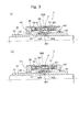
- the select actuator 3 is constituted as described above, and works based on a principle of a linear motor that is constituted by the magnetic moving means 36 disposed on the shift sleeve 35 that serves as the shift lever support member, by the fixed yoke 39 and by the pair of coils 40 and 41. The operation will now be described with reference to Fig. 3.
- a magnetic circuit 368 passing through the N-pole of permanent magnet 361, one moving yoke 362, one coil 40, fixed yoke 39, the other coil 41, the other moving yoke 363 and S-pole of permanent magnet 361, as shown in Figs. 3(a) and 3(b).
- a thrust toward the right is produced by the permanent magnet 361, i.e., produced by the shift sleeve 35, as indicated by an arrow in Fig. 3(a) in accordance with the Fleming's left-hand rule.
- the actuator 3 in the illustrated embodiment has a first select position-limiting means 47 and a second select position-limiting means 48 for limiting the position of the shift lever 34 to the first select position SP1, second select position SP2, third select position SP3 or fourth select position SP4 in cooperation with the magnitude of thrust acting on the magnetic moving means 36, i.e., acting on the shift sleeve 35.
- the first select position-limiting means 47 comprises snap rings 471 and 472 fitted to right end portions (in Figs.
- the thus constituted first select position-limiting means 47 so works that the magnetic moving means 36 moves, i.e., the shift sleeve 35 moves, toward the right in Figs. 1 and 2, and the right end of the shift sleeve 35 in Figs. 1 and 2 comes in contact with the moving ring 474 to be limited for its position.
- the resilient force of the coil spring 473 has been set to be larger than the thrust that acts on the permanent magnet 361, i.e., that acts on the shift sleeve 35.
- the shift sleeve 35 in contact with the moving ring 474 is brought into a halt at a position where the moving ring 474 is in contact with the one snap ring 471.
- the shift lever 34 constituted integratedly with the shift sleeve 35 is brought to the second select position SP2.
- the shift sleeve 35 that has come in contact with the moving ring 474, then, moves toward the right in Figs. 1 and 2 against the resilient force of the coil spring 473, and the moving ring 474 is brought into a halt at a position where the moving ring 474 comes in contact with the stopper 475.
- the shift lever 34 constituted integratedly with the shift sleeve 35 is brought to the first select position SP1.
- the second select position-limiting means 48 comprises snap rings 481 and 482 fitted to left end portions (in Figs. 1 and 2) of the central casing 31b at a predetermined interval, a coil spring 483 disposed between the snap rings 481 and 482, a moving ring 484 disposed between the coil spring 483 and one snap ring 481, and a stopper 485 for limiting the motion of the moving ring 484 by coming in contact therewith when the moving ring 484 is moved toward the left in Figs. 1 and 2 by a predetermined amount.
- the thus constituted second select position-limiting means 48 so works that the permanent magnet 361 moves, i.e., the shift sleeve 35 moves toward the left in Figs. 1 and 2. and the left end of the shift sleeve 35 comes in contact with the moving ring 484 in Figs. 1 and 2 to be limited for its position.
- the resilient force of the coil spring 483 has been set so as to be larger than the thrust that acts on the permanent magnet 361, i.e., that acts on the shift sleeve 35.
- the shift sleeve 35 in contact with the moving ring 484 is brought into a halt at a position where the moving ring 484 is in contact with the one snap ring 481.
- the shift lever 34 constituted integratedly with the shift sleeve 35 is brought to the third select position SP3.
- the thrust acting on the permanent magnet 361, i.e., acting on the shift sleeve 35 has been set so as to become larger than the resilient force of the coil spring 483.
- the shift sleeve 35 that has come in contact with the moving ring 484, then, moves toward the left in Figs. 1 and 2 against the resilient force of the coil spring 483, and the moving ring 484 is brought into a halt at a position where the moving ring 484 comes in contact with the stopper 485.
- the shift lever 34 constituted integratedly with the shift sleeve 35 is brought to the fourth select position SP4.
- the shift lever 34 can be brought to a predetermined select position by controlling the amount of electric power supplied to the pair of coils 40 and 41 without executing the position control operation.
- the gear change device has a select position sensor 8 for detecting the position of the shift sleeve 35 constituted integratedly with the shift lever 34, i.e., for detecting the position thereof in the direction of selection.
- the select position sensor 8 comprises a potentiometer, and a rotary shaft 81 thereof is attached to an end of a lever 82.
- An engaging pin 83 attached to the other end of the lever 82 is brought into engagement with an engaging groove 352 formed in the shift sleeve 35. Therefore, as the shift sleeve 35 moves toward the right or left in Fig.
- the lever 82 swings on the rotary shaft 81 as a center, and the rotary shaft 81 rotates to detect the operation position of the shift sleeve 35, i.e., to detect the position thereof in the direction of selection.
- the shift lever 34 is brought to a desired select position by controlling the voltage and the direction of current supplied to the coils 40 and 41 of the select actuator 3 by using a control means which is not shown.
- the gear change device 2 of the illustrated embodiment has a shift stroke position sensor 9 for detecting the rotational position, i.e., for detecting the shift stroke position of the control shaft 32 mounting the shift sleeve 35 constituted integratedly with the shift lever 34.
- the shift stoke position sensor 9 comprises a potentiometer with its rotary shaft 91 being linked to the control shaft 32. When the control shaft 32 rotates, therefore, the rotary shaft 91 rotates to detect the rotational position, i.e., to detect the shift stroke position, of the control shaft 32.
- Fig. 4 is a sectional view along the line B-B in Fig. 1.
- the shift actuator 5 according to the first embodiment shown in Fig. 4 comprises a casing 51, an operation rod 52 that engages with an operation lever 50 mounted on a control shaft 32 disposed in the central portion of the casing 51 and in the casings 31a, 31b, 31c of the select actuator 3, a magnetic moving means 53 disposed on the outer peripheral surface of the operation rod 52, a cylindrical fixed yoke 54 disposed on the inside of the casing 51 to surround the magnetic moving means 53, and a pair of coils 55 and 56 provided on the inside of the fixed yoke 54 neighboring in the axial direction.
- the operation lever 50 that engages with the operation rod 52 has a hole 501 formed in the base portion thereof so as to be fitted to the control shaft 32.
- the operation lever 50 By fitting a key 503 to a key groove 502 formed in the inner peripheral surface of the hole 501 and to a key groove 322 formed in the outer peripheral surface of the control shaft 32, the operation lever 50 turns integratedly with the control shaft 32.
- the operation lever 50 works as an operation member which is linked to the shift lever 34 via the control shaft 32 and the shift sleeve 35, and is disposed being inserted in the opening 311a formed in the lower part of the casing 31a which is on the left side in Figs. 1 and 2.
- the casing 51 is formed in a cylindrical shape by using a nonmagnetic material such as a stainless steel or an aluminum alloy.
- the operation rod 52 is made of a nonmagnetic material such as a stainless steel, and has a groove 521 formed at a left end portion thereof in Fig. 4, the groove 521 being constituted so as to be engaged with an end of the operation lever 50.
- the magnetic moving means 53 comprises a moving yoke 531 mounted on the outer peripheral surface of the operation rod 52, and an annular permanent magnet 532 disposed on the outer peripheral surface of the moving yoke 531 so as to be faced the inner peripheral surfaces of the pair of coils 55 and 56.
- the moving yoke 531 is made of a magnetic material, and has a cylindrical portion 531a on which a permanent magnet 532 is mounted, and annular flanges 531b and 531c formed at both ends of the cylindrical portion 531a, the outer peripheral surfaces of the flanges 531b and 531c being located close to the inner peripheral surface of the fixed yoke 54.
- the gap between the outer peripheral surfaces of the flanges 531b, 531c and the inner peripheral surface of the fixed yoke 54 be as small as possible.
- the gap in the illustrated embodiment is set to be 0.5 mm.
- the thus constituted moving yoke 531 is limited from moving in the axial directions by snap rings 535 and 536 respectively mounted on the operation rod 52 on both sides thereof.
- the permanent magnet 532 has magnetic poles in the outer peripheral surface and in the inner peripheral surface thereof. In the illustrated embodiment, the N-pole is formed in the outer peripheral surface and the S-pole is formed in the inner peripheral surface.
- the thus formed permanent magnet 532 is mounted on the outer peripheral surface of the cylindrical portion 531a of the moving yoke 531 and is limited from moving in the axial direction by snap rings 533 and 534 respectively mounted on the cylindrical portion 531a of the moving yoke 531 on both sides thereof.
- the fixed yoke 54 is mounted on the inner peripheral surface of the casing 51 formed of the magnetic material.
- the pair of coils 55 and 56 is wound on a bobbin 57 that is made of a nonmagnetic material such as a synthetic resin and is mounted on the inner peripheral surface of the fixed yoke 54.
- the pair of coils 55 and 56 is connected to a power source circuit that is not shown.
- the length of the pair of coils 55 and 56 in the axial direction is suitably set according to the operation stroke of the shift actuator 5.
- End walls 61 and 62 are mounted on both sides of the casing 51.
- the end walls 61 and 62 are formed of a stainless steel or an aluminum alloy, or a nonmagnetic material such as a synthetic resin, and have holes 611 and 621 formed in the central portions thereof to permit the insertion of the operation rod 52.
- the operation rod 52 inserted in the holes 611 and 621 is supported by the inner peripheral surfaces of the holes 611 and 521 slidably in the axial direction.
- Cut-away portions 612 and 622 are formed in the inner peripheral portions of the end walls 61 and 62 on the outer sides thereof, and sealing members 63 and 64 are fitted into the cut-away portions 612 and 622.
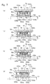
- the shift actuator 5 according to the first embodiment is constituted as described. The operation will now be described with reference to Fig. 5.
- a first magnetic flux circuit 537 and a second magnetic flux circuit 538 are formed by the permanent magnet 532. That is, in the shift actuator 5 of the illustrated embodiment, there are established a first magnetic circuit 537 passing through the N-pole of the permanent magnet 532, one coil 55 of the pair of coils, fixed yoke 54, flange 531b of the moving yoke 531, cylindrical portion 531a of the moving yoke 531 and S-pole of the permanent magnet 532, and a second magnetic circuit 538 passing through the N-pole of the permanent magnet 532, the other coil 56 of the pair of coils, fixed yoke 54, flange 531c of the moving yoke 531, cylindrical portion 531a of the moving yoke 531 and S-pole of the permanent magnet 532.
- the thrust toward the right produced on the magnetic moving means 53 i.e., produced on the operation rod 52 as a result of supplying electric current to the other coil 56 in the direction shown in Fig. 5(d)
- the thrust toward the left produced on the magnetic moving means 53 i.e., produced on the operation rod 52 as a result of supplying electric current to one coil 55 in the direction shown in Fig. 5(d).
- the operation rod 52 moves toward the right in Fig. 5(d).
- the amount of magnetic flux passing through the coil 55 decreases and the amount of magnetic flux passing through the coil 56 increases as it approaches neutral position.
- the amount of magnetic flux passing through the coil 55 becomes equal to the amount of magnetic flux passing through the coil 56.
- the leftward thrust becomes equal to the rightward thrust on the operation rod 52; i.e., the operation rod 52 comes into a halt at the neutral position.
- the operation rod 52 operates based on the principle of a linear motor which is constituted by the magnetic moving means 53, fixed yoke 54 and the pair of coils 55 and 56, featuring improved durability since there is employed no rotary mechanism.
- the shift actuator 5 of the first embodiment requires no speed reduction mechanism which is based on the ball-screw mechanism or the gear mechanism, and can, hence, be constituted in a compact size and operates at an increased speed.
- the flanges 531a and 531c of the moving yoke 531 constituting the magnetic moving means 53 have outer peripheral surfaces which are located close to the inner peripheral surface of the fixed yoke 54. Therefore, a large gap to the magnetic flux is formed by the coils 55 and 56 only, and the air gap is minimized in the first magnetic flux circuit 537 and in the second magnetic flux circuit 538 established by the permanent magnet 532, making it possible to produce a large thrust.
- the shift actuator 5a according to the second embodiment shown in Fig. 6 has a magnetic moving means 53a disposed on the operation rod 52, which is different from the magnetic moving means 53 of the shift actuator 5 of the first embodiment.
- Other constituent members may be substantially the same as those of the shift actuator 5 of the first embodiment. In Fig. 6, therefore, the same constituent members as those constituting the shift actuator 5 of the first embodiment are denoted by the same reference numerals.
- the magnetic moving means 53a constituting the shift actuator 5a of the second embodiment includes an intermediate yoke 530a disposed on the outer peripheral surface of the operation rod 52 so as to be opposed to the inner peripheral surfaces of the pair of coils 55 and 56, a pair of permanent magnets 532a and 533a disposed on both sides of the intermediate yoke 530a to hold it therebetween, and a pair of moving yokes 534a and 535a disposed on the outer sides of the pair of permanent magnets 532a and 533a in the axial direction thereof.
- the intermediate yoke 530a is made of a magnetic material in an annular shape.
- the pair of permanent magnets 532a and 533a has magnetic poles in both end surfaces in the axial direction thereof.
- the N-pole is formed in the opposing end surfaces
- the S-pole is formed in the end surfaces on the outer sides in the axial direction thereof.
- the pair of moving yokes 534a and 535a is made of a magnetic material, and has cylindrical portions 534c and 535c and annular flanges 534d and 535d formed at the outer ends of the cylindrical portions 534c and 535c in the axial direction, respectively.
- the outer peripheral surfaces of the flanges 534d and 535d are located close to the inner peripheral surface of the fixed yoke 54.
- the gap between the outer peripheral surfaces of the flanges 534d, 535d and the inner peripheral surface of the fixed yoke 54 is set to be 0.5 mm, like that of the shift actuator 5 of the above-mentioned first embodiment.
- the above-mentioned pair of moving yokes 534a and 535a in the illustrated embodiment, is constituted by the cylindrical portions 534c, 535c and by the flanges 534d, 535d.
- the pair of moving yokes may be constituted by the flanges only having the outer peripheral surfaces located close to the inner peripheral surface of the fixed yoke 54.
- the thus constituted pair of moving yokes 534a and 535a is limited from moving in the axial direction by snap rings 58a and 59a mounted on the operation rod 52 on the outer sides thereof in the axial direction.
- the shift actuator 5a according to the second embodiment is constituted as described. The operation will now be described with reference to Fig. 7.
- a first magnetic flux circuit 537a and a second magnetic flux circuit 538a are formed by the pair of permanent magnets 532a and 533a.
- a thrust acts on the magnetic moving means 53a, i.e., on the operation rod 52, toward the left in Fig. 7(d) due to the electric current flowing into one coil 55.
- the leftward thrust due to the current flowing into one coil 55 increases as the magnetic moving means 53a, i.e., as the operation rod 52, approaches the neutral position.
- the magnetic moving means 53a i.e., the operation rod 52
- the magnetic moving means 53a i.e., the operation rod 52
- the magnetic moving means 53a arrives at the neutral position
- the leftward thrust due to the current flowing into one coil 55 becomes equal to the rightward thrust due to the current flowing into the other coil 56.
- the magnetic moving means 53a i.e., the operation rod 52, comes into a halt at the neutral position.
- the pair of permanent magnets 532a and 533a that constitutes the magnetic moving means 53a is disposed to hold the intermediate yoke 530a therebetween, and the N-pole is formed in the opposing end surfaces of the pair of permanent magnets 532a and 533a. Accordingly, the magnetic fluxes from the two permanent magnets 532a and 533a travel toward the pair of coils 55 and 56 while repelling each other. In the shift actuator 5a according to the second embodiment, therefore, the magnetic fluxes pass through the pair of coils 55 and 56 at right angles thereto and, hence, an increased thrust is produced on the magnetic moving means 53a, i.e., on the operation rod 52.
- the S-pole may be formed in the end surfaces facing each other of the pair of permanent magnets 532a and 533a. Namely, it is desired that the same pole be formed in the end surfaces facing each other of the pair of permanent magnets 532a and 533a.
- the inner peripheral surface of the fixed yoke 54 is close to the outer peripheral surfaces of the flanges 534d and 535d of the pair of moving yokes 534a and 535a constituting the magnetic moving means 53a. Therefore, a large air gap to the magnetic flux is formed by the pair of coils 55 and 56 only. In the shift actuator 5a of the second embodiment, therefore, the air gap is minimized in the magnetic flux circuits established by the pair of permanent magnets 532a and 533a and hence, a large thrust is obtained.
- the shift actuator according to the present invention can be applied also to, for example, a shift-assisting device for assisting the force of operation in the shifting direction in the manual transmissions.
- the shift actuator for a transmission according to the present invention is constituted as described above, and exhibits action and effect as described below.
- the operation rod operates based on the principle of a linear motor that is constituted by a magnetic moving means, a fixed yoke and a pair of coils. Therefore, the shift actuator features improved durability since it has no rotary mechanism and features a compact constitution and an increased operation speed since it needs no speed reduction mechanism constituted by a ball-screw mechanism or a gear that is employed by the actuator that uses an electric motor.
Landscapes
- Engineering & Computer Science (AREA)
- General Engineering & Computer Science (AREA)
- Mechanical Engineering (AREA)
- Gear-Shifting Mechanisms (AREA)
- Reciprocating, Oscillating Or Vibrating Motors (AREA)
Abstract
Description
- The present invention relates to a shift actuator for a transmission, which actuates, in a direction of shift, a shift lever of the transmission mounted on a vehicle.
- As the shift actuator for a transmission, which actuates, in a direction of shift, a shift lever of the transmission, there has been generally used a fluid pressure cylinder that utilizes the fluid pressure such as air pressure or hydraulic pressure as a source of actuation. The shift actuator using the fluid pressure cylinders requires a piping for connecting the source of fluid pressure to the actuators, an electromagnetic change-over valve for changing over the flow passage of the operation fluid, and space for the arrangement thereof, resulting in an increase in the weight of the device as a whole.
- In recent years, there has been proposed an actuator constituted by an electric motor as a shift actuator for a transmission mounted on a vehicle which is provided with neither a source of the compressed air nor a source of the hydraulic pressure. The shift actuator constituted by the electric motor needs neither the piping for connection to the source of fluid pressure nor the electromagnetic change-over valve, unlike the actuators that use fluid pressure cylinders, and can, hence, be constituted in a compact size as a whole and in a reduced weight.
- The actuator using an electric motor needs a speed reduction mechanism for obtaining a predetermined actuating force. As the speed reduction mechanism, there have been proposed the one using a ball-screw mechanism and the one using a gear mechanism. However, the actuators using the ball-screw mechanism and gear mechanism are not necessarily satisfactory in regard to the durability of the ball-screw mechanism and the gear mechanism and in regard to the durability and the operation speed of the electric motor.
- It is an object of the present invention to provide a shift actuator for a transmission, which features excellent durability and a high operation speed.
- In order to achieve the above-mentioned object according to the present invention, there is provided a shift actuator for a transmission, which actuates, in a direction of shift, a shift lever of the transmission, the shift actuator comprising:
- an operation rod that engages with an operation member linked to the shift lever;
- a magnetic moving means disposed on the outer peripheral surface of the operation rod;
- a cylindrical fixed yoke surrounding the magnetic moving means; and
- a pair of coils arranged on the inside of the fixed yoke neighboring in the axial direction.
-
- The magnetic moving means comprises a moving yoke mounted on the outer peripheral surface of the operation rod, and an annular permanent magnet mounted on the outer peripheral surface of the moving yoke and having magnetic poles in the outer peripheral surface and in the inner peripheral surface thereof, and the moving yoke has a cylindrical portion on which the permanent magnet is mounted and annular flanges formed at both ends of the cylindrical portion, the outer peripheral surfaces of the flanges being constituted to be located close to the inner peripheral surface of the fixed yoke.
- Further, the magnetic moving means comprises an intermediate yoke mounted on the outer peripheral surface of the operation rod, a pair of annular permanent magnets disposed each on both sides of the intermediate yoke to hold it therebetween and having magnetic poles in both end surfaces thereof in the axial direction, and a pair of moving yokes disposed each on the outer sides of the pair of permanent magnets in the axial direction thereof, and the pair of moving yokes has annular flanges which are so constituted that the outer peripheral surfaces of said moving yokes are located close to the inner peripheral surface of said fixed yoke.
- It is desired that the pair of permanent magnets have their opposing end surfaces magnetized into the same polarity.
-
- Fig. 1 is a sectional view illustrating a gear change device provided with a shift actuator constituted according to a first embodiment of the present invention;
- Fig. 2 is a sectional view along the line A-A in Fig. 1;
- Fig. 3 is a view illustrating the operation of a select actuator that constitutes the gear change device shown in Fig. 1;
- Fig. 4 is a sectional view along the line B-B in Fig. 1;
- Fig. 5 is a view illustrating the operation states of the shift actuator according to the first embodiment shown in Fig. 4;
- Fig. 6 is a sectional view illustrating the shift actuator constituted according to a second embodiment of the present invention; and
- Fig. 7 is a view illustrating the operation states of the shift actuator according to the second embodiment shown in Fig. 5.
-
- Preferred embodiments of the shift actuator for a transmission constituted according to the present invention will now be described in further detail with reference to the accompanying drawings.
- Fig. 1 is a sectional view illustrating a gear change device provided with a shift actuator constituted according to a first embodiment of the present invention, and Fig. 2 is a sectional view along the line A-A in Fig. 1.
- A
gear change device 2 according to the illustrated embodiment is constituted by aselect actuator 3 and ashift actuator 5. Theselect actuator 3 has threecylindrical casings control shaft 32 is arranged in the threecasings control shaft 32 are rotatably supported by thecasings bearings spline 321 is formed in an intermediate portion of thecontrol shaft 32. Acylindrical shift sleeve 35 constituted integratedly with ashift lever 34 is spline-fitted to thespline 321 so as to slide in the axial direction. Theshift lever 34 and theshift sleeve 35 are made of a nonmagnetic material such as a stainless steel, and theshift lever 34 is disposed, being inserted, in an opening 311b formed in a lower portion of thecentral casing 31b. An end of theshift lever 34 is so constituted as to suitably engage withshift blocks - A
magnetic moving means 36 is disposed on the outer peripheral surface of theshift sleeve 35. Themagnetic moving means 36 is constituted by an annularpermanent magnet 361 that is mounted on the outer peripheral surface of theshift sleeve 35 and has magnetic poles in both end surfaces in the axial direction and by a pair ofmoving yokes permanent magnet 361 in the axial direction thereof. Thepermanent magnet 361 in the illustrated embodiment is magnetized into an N-pole in the right end surface in Figs. 1 and 2, and is magnetized into an S-pole in the left end surface in Figs. 1 and 2. The above pair of movingyokes magnetic moving means 36 is positioned at its right end (Figs. 1 and 2) of the one moving yoke 362 (right side in Figs. 1 and 2) by astep 351 formed in theshift sleeve 35, and is positioned at its left end (Figs. 1 and 2) of the other moving yoke 363 (left side in Figs. 1 and 2) by asnap ring 37 fitted to theshift sleeve 35, so that the motion in the axial direction thereof is limited. Afixed yoke 39 is disposed on the outer peripheral side of the magnetic moving means 36 to surround the magnetic moving means 36. Thefixed yoke 39 is made of a magnetic material in a cylindrical shape and is mounted on the inner peripheral surface of thecentral casing 31b. A pair ofcoils fixed yoke 39. The pair ofcoils bobbin 42 made of a nonmagnetic material such as a synthetic resin and is mounted on the inner peripheral surface of thefixed yoke 39. The pair ofcoils coil 40 in the axial direction nearly corresponds to a length of selection from the first select position SP1 up to the fourth select position SP4.End walls fixed yoke 39. On the inner periphery of theend walls members shift sleeve 35. - The
select actuator 3 is constituted as described above, and works based on a principle of a linear motor that is constituted by the magnetic movingmeans 36 disposed on theshift sleeve 35 that serves as the shift lever support member, by thefixed yoke 39 and by the pair ofcoils - In the
select actuator 3 according to the first embodiment, there is established amagnetic circuit 368 passing through the N-pole ofpermanent magnet 361, onemoving yoke 362, onecoil 40,fixed yoke 39, theother coil 41, the other movingyoke 363 and S-pole ofpermanent magnet 361, as shown in Figs. 3(a) and 3(b). In this state, when electric currents are supplied to the pair ofcoils permanent magnet 361, i.e., produced by theshift sleeve 35, as indicated by an arrow in Fig. 3(a) in accordance with the Fleming's left-hand rule. As shown in Fig. 3(b), on the other hand, when the electric currents are supplied to the pair ofcoils permanent magnet 361, i.e., produced by theshift sleeve 35, as indicated by an arrow in Fig. 3(b) in accordance with the Fleming's left-hand rule. The magnitude of thrust produced by thepermanent magnet 361, i.e., produced by theshift sleeve 35, is determined by the amount of electric power supplied to the pair ofcoils - The
actuator 3 in the illustrated embodiment has a first select position-limiting means 47 and a second select position-limiting means 48 for limiting the position of theshift lever 34 to the first select position SP1, second select position SP2, third select position SP3 or fourth select position SP4 in cooperation with the magnitude of thrust acting on the magnetic moving means 36, i.e., acting on theshift sleeve 35. The first select position-limiting means 47 comprisessnap rings central casing 31b at a predetermined interval, acompression coil spring 473 disposed between thesnap rings ring 474 disposed between thecompression coil spring 473 and onesnap ring 471, and astopper 475 for limiting the motion of the movingring 474 by coming in contact therewith when the movingring 474 is moved toward the right in Figs. 1 and 2 by a predetermined amount. - When in a state as shown in Figs 1 and 2, a current is supplied to the pair of
coils shift sleeve 35 moves, toward the right in Figs. 1 and 2, and the right end of theshift sleeve 35 in Figs. 1 and 2 comes in contact with the movingring 474 to be limited for its position. In this state, the resilient force of thecoil spring 473 has been set to be larger than the thrust that acts on thepermanent magnet 361, i.e., that acts on theshift sleeve 35. Therefore, the shift sleeve 35 in contact with the movingring 474 is brought into a halt at a position where the movingring 474 is in contact with the onesnap ring 471. In this case, theshift lever 34 constituted integratedly with theshift sleeve 35 is brought to the second select position SP2. Next, when the current is supplied to the pair ofcoils shift sleeve 35 has been set so as to become larger than the resilient force of thecoil spring 473. Accordingly, theshift sleeve 35 that has come in contact with the movingring 474, then, moves toward the right in Figs. 1 and 2 against the resilient force of thecoil spring 473, and the movingring 474 is brought into a halt at a position where the movingring 474 comes in contact with thestopper 475. At this moment, theshift lever 34 constituted integratedly with theshift sleeve 35 is brought to the first select position SP1. - Next, the second select position-limiting
means 48 will be described. - The second select position-limiting
means 48 comprises snap rings 481 and 482 fitted to left end portions (in Figs. 1 and 2) of thecentral casing 31b at a predetermined interval, acoil spring 483 disposed between the snap rings 481 and 482, a movingring 484 disposed between thecoil spring 483 and onesnap ring 481, and astopper 485 for limiting the motion of the movingring 484 by coming in contact therewith when the movingring 484 is moved toward the left in Figs. 1 and 2 by a predetermined amount. - When in a state as shown in Figs. 1 and 2, a current is supplied to the pair of
coils means 48 so works that thepermanent magnet 361 moves, i.e., theshift sleeve 35 moves toward the left in Figs. 1 and 2. and the left end of theshift sleeve 35 comes in contact with the movingring 484 in Figs. 1 and 2 to be limited for its position. In this state, the resilient force of thecoil spring 483 has been set so as to be larger than the thrust that acts on thepermanent magnet 361, i.e., that acts on theshift sleeve 35. Therefore, theshift sleeve 35 in contact with the movingring 484 is brought into a halt at a position where the movingring 484 is in contact with the onesnap ring 481. In this case, theshift lever 34 constituted integratedly with theshift sleeve 35 is brought to the third select position SP3. Next, when the current is supplied to the pair ofcoils permanent magnet 361, i.e., acting on theshift sleeve 35 has been set so as to become larger than the resilient force of thecoil spring 483. Accordingly, theshift sleeve 35 that has come in contact with the movingring 484, then, moves toward the left in Figs. 1 and 2 against the resilient force of thecoil spring 483, and the movingring 484 is brought into a halt at a position where the movingring 484 comes in contact with thestopper 485. At this moment, theshift lever 34 constituted integratedly with theshift sleeve 35 is brought to the fourth select position SP4. - As described above, according to the illustrated embodiment provided with the first select position-limiting
means 47 and with the second select position-limitingmeans 48, theshift lever 34 can be brought to a predetermined select position by controlling the amount of electric power supplied to the pair ofcoils - The gear change device according to the illustrated embodiment has a
select position sensor 8 for detecting the position of theshift sleeve 35 constituted integratedly with theshift lever 34, i.e., for detecting the position thereof in the direction of selection. Theselect position sensor 8 comprises a potentiometer, and arotary shaft 81 thereof is attached to an end of alever 82. An engagingpin 83 attached to the other end of thelever 82 is brought into engagement with an engaginggroove 352 formed in theshift sleeve 35. Therefore, as theshift sleeve 35 moves toward the right or left in Fig. 2, thelever 82 swings on therotary shaft 81 as a center, and therotary shaft 81 rotates to detect the operation position of theshift sleeve 35, i.e., to detect the position thereof in the direction of selection. In response to a signal from theselect position sensor 8, theshift lever 34 is brought to a desired select position by controlling the voltage and the direction of current supplied to thecoils select actuator 3 by using a control means which is not shown. - Further, the
gear change device 2 of the illustrated embodiment has a shiftstroke position sensor 9 for detecting the rotational position, i.e., for detecting the shift stroke position of thecontrol shaft 32 mounting theshift sleeve 35 constituted integratedly with theshift lever 34. The shift stokeposition sensor 9 comprises a potentiometer with itsrotary shaft 91 being linked to thecontrol shaft 32. When thecontrol shaft 32 rotates, therefore, therotary shaft 91 rotates to detect the rotational position, i.e., to detect the shift stroke position, of thecontrol shaft 32. - Next, the shift actuator constituted according to the first embodiment of the present invention will be described with reference chiefly to Fig. 4 which is a sectional view along the line B-B in Fig. 1.
- The
shift actuator 5 according to the first embodiment shown in Fig. 4 comprises acasing 51, anoperation rod 52 that engages with anoperation lever 50 mounted on acontrol shaft 32 disposed in the central portion of thecasing 51 and in thecasings select actuator 3, a magnetic moving means 53 disposed on the outer peripheral surface of theoperation rod 52, a cylindrical fixedyoke 54 disposed on the inside of thecasing 51 to surround the magnetic moving means 53, and a pair ofcoils yoke 54 neighboring in the axial direction. Theoperation lever 50 that engages with theoperation rod 52 has ahole 501 formed in the base portion thereof so as to be fitted to thecontrol shaft 32. By fitting a key 503 to akey groove 502 formed in the inner peripheral surface of thehole 501 and to akey groove 322 formed in the outer peripheral surface of thecontrol shaft 32, theoperation lever 50 turns integratedly with thecontrol shaft 32. Theoperation lever 50 works as an operation member which is linked to theshift lever 34 via thecontrol shaft 32 and theshift sleeve 35, and is disposed being inserted in theopening 311a formed in the lower part of thecasing 31a which is on the left side in Figs. 1 and 2. - In the illustrated embodiment, the
casing 51 is formed in a cylindrical shape by using a nonmagnetic material such as a stainless steel or an aluminum alloy. Theoperation rod 52 is made of a nonmagnetic material such as a stainless steel, and has agroove 521 formed at a left end portion thereof in Fig. 4, thegroove 521 being constituted so as to be engaged with an end of theoperation lever 50. - The magnetic moving means 53 comprises a moving
yoke 531 mounted on the outer peripheral surface of theoperation rod 52, and an annularpermanent magnet 532 disposed on the outer peripheral surface of the movingyoke 531 so as to be faced the inner peripheral surfaces of the pair ofcoils yoke 531 is made of a magnetic material, and has acylindrical portion 531a on which apermanent magnet 532 is mounted, andannular flanges cylindrical portion 531a, the outer peripheral surfaces of theflanges yoke 54. It is desired that the gap between the outer peripheral surfaces of theflanges yoke 54 be as small as possible. By taking errors in the production and the like into consideration, however, the gap in the illustrated embodiment is set to be 0.5 mm. The thus constituted movingyoke 531 is limited from moving in the axial directions bysnap rings operation rod 52 on both sides thereof. Thepermanent magnet 532 has magnetic poles in the outer peripheral surface and in the inner peripheral surface thereof. In the illustrated embodiment, the N-pole is formed in the outer peripheral surface and the S-pole is formed in the inner peripheral surface. The thus formedpermanent magnet 532 is mounted on the outer peripheral surface of thecylindrical portion 531a of the movingyoke 531 and is limited from moving in the axial direction bysnap rings cylindrical portion 531a of the movingyoke 531 on both sides thereof. - The fixed
yoke 54 is mounted on the inner peripheral surface of thecasing 51 formed of the magnetic material. The pair ofcoils bobbin 57 that is made of a nonmagnetic material such as a synthetic resin and is mounted on the inner peripheral surface of the fixedyoke 54. The pair ofcoils coils shift actuator 5. -
End walls casing 51. Theend walls holes operation rod 52. Theoperation rod 52 inserted in theholes holes portions end walls members portions - The
shift actuator 5 according to the first embodiment is constituted as described. The operation will now be described with reference to Fig. 5. - In the
shift actuator 5 as shown in Figs. 5(a) to 5(d), a firstmagnetic flux circuit 537 and a secondmagnetic flux circuit 538 are formed by thepermanent magnet 532. That is, in theshift actuator 5 of the illustrated embodiment, there are established a firstmagnetic circuit 537 passing through the N-pole of thepermanent magnet 532, onecoil 55 of the pair of coils, fixedyoke 54,flange 531b of the movingyoke 531,cylindrical portion 531a of the movingyoke 531 and S-pole of thepermanent magnet 532, and a secondmagnetic circuit 538 passing through the N-pole of thepermanent magnet 532, theother coil 56 of the pair of coils, fixedyoke 54,flange 531c of the movingyoke 531,cylindrical portion 531a of the movingyoke 531 and S-pole of thepermanent magnet 532. - When the electric currents are supplied into the pair of
coils operation rod 52 is at the neutral position shown in Fig. 5(a), thrusts are produced on the magnetic moving means 53, i.e., on theoperation rod 52 according to the Fleming's left-hand rule in the directions to cancel each other as indicated by arrows. Therefore, theoperation rod 52 is maintained at the neutral position shown in Figs. 4 and 5(a). - Next, when the electric currents are supplied to the pair of
coils operation rod 52 is at the neutral position, the thrust is produced on the magnetic moving means 53, i.e., on theoperation rod 52 toward the left as indicated by an arrow in Fig. 5(b). As a result, theoperation rod 52 moves toward the left in Fig. 4, whereby thecontrol shaft 32 rotates clockwise in Fig. 4 via theoperation lever 50 which is engaged at its end with theoperation rod 52. Accordingly, theshift lever 34 constituted integratedly with theshift sleeve 35 mounted on thecontrol shaft 32, is shifted in one direction. - When the electric currents are supplied to the pair of
coils operation rod 52 is at the neutral position, the thrust is produced on the magnetic moving means 53, i.e., on theoperation rod 52 toward the right as indicated by an arrow in Fig. 5(c). As a result, theoperation rod 52 moves toward the right in Fig. 4, whereby thecontrol shaft 32 rotates counterclockwise in Fig. 4 via theoperation lever 50. Accordingly, theshift lever 34 constituted integratedly with theshift sleeve 35 mounted on thecontrol shaft 32, is shifted in the other direction. - On the other hand, when the electric currents are supplied to the pair of
coils operation rod 52 has been moved toward the left in Fig. 4, the thrusts are produced on the magnetic moving means 53, i.e., on theoperation rod 52 in the directions to cancel each other as indicated by an arrows. Here, in the state where theoperation rod 52 has been moved toward the left, i.e., the magnetic moving means 53 has been moved toward the left, there is produced magnetic fluxes that passes through the coil due to the firstmagnetic flux circuit 537 and the secondmagnetic flux circuit 538 established by thepermanent magnet 532. In this case, however, the amount of magnetic flux passing through thecoil 56 is larger than the amount of magnetic flux passing through thecoil 55. Therefore, the thrust toward the right produced on the magnetic moving means 53, i.e., produced on theoperation rod 52 as a result of supplying electric current to theother coil 56 in the direction shown in Fig. 5(d), becomes greater than the thrust toward the left produced on the magnetic moving means 53, i.e., produced on theoperation rod 52 as a result of supplying electric current to onecoil 55 in the direction shown in Fig. 5(d). As a result, theoperation rod 52 moves toward the right in Fig. 5(d). Thus, when theoperation rod 52 moves toward the right in Fig. 5(d), the amount of magnetic flux passing through thecoil 55 decreases and the amount of magnetic flux passing through thecoil 56 increases as it approaches neutral position. When theoperation rod 52 has reached the neutral position, the amount of magnetic flux passing through thecoil 55 becomes equal to the amount of magnetic flux passing through thecoil 56. As a result, the leftward thrust becomes equal to the rightward thrust on theoperation rod 52; i.e., theoperation rod 52 comes into a halt at the neutral position. - In the
shift actuator 5 according to the first embodiment as described above, theoperation rod 52 operates based on the principle of a linear motor which is constituted by the magnetic moving means 53, fixedyoke 54 and the pair ofcoils shift actuator 5 of the first embodiment requires no speed reduction mechanism which is based on the ball-screw mechanism or the gear mechanism, and can, hence, be constituted in a compact size and operates at an increased speed. In theshift actuator 5 of the first embodiment, further, theflanges yoke 531 constituting the magnetic moving means 53 have outer peripheral surfaces which are located close to the inner peripheral surface of the fixedyoke 54. Therefore, a large gap to the magnetic flux is formed by thecoils magnetic flux circuit 537 and in the secondmagnetic flux circuit 538 established by thepermanent magnet 532, making it possible to produce a large thrust. - Next, a second embodiment of the shift actuator constituted according to the present invention will be described with reference to Figs. 6 and 7.
- The
shift actuator 5a according to the second embodiment shown in Fig. 6 has a magnetic moving means 53a disposed on theoperation rod 52, which is different from the magnetic moving means 53 of theshift actuator 5 of the first embodiment. Other constituent members, however, may be substantially the same as those of theshift actuator 5 of the first embodiment. In Fig. 6, therefore, the same constituent members as those constituting theshift actuator 5 of the first embodiment are denoted by the same reference numerals. - The magnetic moving means 53a constituting the
shift actuator 5a of the second embodiment includes anintermediate yoke 530a disposed on the outer peripheral surface of theoperation rod 52 so as to be opposed to the inner peripheral surfaces of the pair ofcoils permanent magnets intermediate yoke 530a to hold it therebetween, and a pair of movingyokes permanent magnets intermediate yoke 530a is made of a magnetic material in an annular shape. The pair ofpermanent magnets yokes cylindrical portions annular flanges cylindrical portions flanges yoke 54. The gap between the outer peripheral surfaces of theflanges yoke 54 is set to be 0.5 mm, like that of theshift actuator 5 of the above-mentioned first embodiment. The above-mentioned pair of movingyokes cylindrical portions flanges yoke 54. The thus constituted pair of movingyokes snap rings operation rod 52 on the outer sides thereof in the axial direction. - The
shift actuator 5a according to the second embodiment is constituted as described. The operation will now be described with reference to Fig. 7. - In the
shift actuator 5a according to the second embodiment as shown in Figs. 7(a) to 7(d), a firstmagnetic flux circuit 537a and a secondmagnetic flux circuit 538a are formed by the pair ofpermanent magnets - When the electric currents are supplied into the pair of
coils operation rod 52 is at the neutral position shown in Fig. 7(a), thrusts are produced on the magnetic moving means 53a, i.e., on theoperation rod 52, according to the Fleming's left-hand rule in the directions to cancel each other as indicated by arrows. Therefore, theoperation rod 52 is maintained at the neutral position shown in Figs. 6 and 7(a). - Next, when the electric currents are supplied to the pair of
coils operation rod 52 is at the neutral position, the thrust is produced on the magnetic moving means 53a, i.e., on theoperation rod 52, toward the left as indicated by an arrow in Fig. 7(b). As a result, theoperation rod 52 moves toward the left in Fig. 7(b). - When the electric currents are supplied to the pair of
coils operation rod 52 is at the neutral position, the thrust is produced on the magnetic moving means 53a, i.e., on theoperation rod 52, toward the right as indicated by an arrow in Fig. 7(c). As a result, theoperation rod 52 moves toward the right in Fig. 7(c). - On the other hand, when the electric currents are supplied to the pair of
coils operation rod 52 is moved toward the left in Fig. 6, the thrust toward the right is produced on the magnetic moving means 53a, i.e., on theoperation rod 52 as indicated by an arrow in Fig. 7(d) due to the current flowing into theother coil 56, since both the firstmagnetic flux circuit 537 and the secondmagnetic flux circuit 538 are passing through theother coil 56. Thus, as theoperation rod 52 moves toward the right in Fig. 7(d) and approaches the neutral position, the firstmagnetic flux circuit 537a formed by thepermanent magnet 532a passes through onecoil 55. Therefore, a thrust acts on the magnetic moving means 53a, i.e., on theoperation rod 52, toward the left in Fig. 7(d) due to the electric current flowing into onecoil 55. The leftward thrust due to the current flowing into onecoil 55 increases as the magnetic moving means 53a, i.e., as theoperation rod 52, approaches the neutral position. Then, as the magnetic moving means 53a, i.e., theoperation rod 52, arrives at the neutral position, the leftward thrust due to the current flowing into onecoil 55 becomes equal to the rightward thrust due to the current flowing into theother coil 56. As a result, the magnetic moving means 53a, i.e., theoperation rod 52, comes into a halt at the neutral position. - In the
shift actuator 5a according to the second embodiment as described above, the pair ofpermanent magnets intermediate yoke 530a therebetween, and the N-pole is formed in the opposing end surfaces of the pair ofpermanent magnets permanent magnets coils shift actuator 5a according to the second embodiment, therefore, the magnetic fluxes pass through the pair ofcoils operation rod 52. Here, the S-pole may be formed in the end surfaces facing each other of the pair ofpermanent magnets permanent magnets shift actuator 5a of the second embodiment, further, the inner peripheral surface of the fixedyoke 54 is close to the outer peripheral surfaces of theflanges yokes coils shift actuator 5a of the second embodiment, therefore, the air gap is minimized in the magnetic flux circuits established by the pair ofpermanent magnets - In the foregoing were described the embodiments in which the invention was applied to the shift actuator that constitutes, together with the select actuator, the gear change device. The shift actuator according to the present invention can be applied also to, for example, a shift-assisting device for assisting the force of operation in the shifting direction in the manual transmissions.
- The shift actuator for a transmission according to the present invention is constituted as described above, and exhibits action and effect as described below.
- That is, according to the present invention, the operation rod operates based on the principle of a linear motor that is constituted by a magnetic moving means, a fixed yoke and a pair of coils. Therefore, the shift actuator features improved durability since it has no rotary mechanism and features a compact constitution and an increased operation speed since it needs no speed reduction mechanism constituted by a ball-screw mechanism or a gear that is employed by the actuator that uses an electric motor.
Claims (4)
- A shift actuator (5; 5a) for a transmission, which actuates, in a direction of shift, a shift lever (34) of the transmission, the shift actuator(5; 5a) comprising:an operation rod (52) that engages with an operation member (50) linked to said shift lever (34);a magnetic moving means (53; 53a) disposed on the outer peripheral surface of said operation rod (52);a cylindrical fixed yoke (54) surrounding said magnetic moving means (53; 53a); anda pair of coils (55, 56) arranged on the inside of said fixed yoke (54) neighboring in the axial direction.
- A shift actuator (5) for a transmission according to claim 1, wherein:said magnetic moving means (53) comprises a moving yoke (531) mounted on the outer peripheral surface of said operation rod (52), and an annular permanent magnet (532) mounted on the outer peripheral surface of said moving yoke (531) and having magnetic poles in the outer peripheral surface and in the inner peripheral surface thereof; andsaid moving yoke (531) has a cylindrical portion (531a) on which said permanent magnet (532) is mounted, and annular flanges (531b, 531c) formed at both ends of said cylindrical portion (531a); the outer peripheral surfaces of said flanges (531b, 531c) being constituted to be located close to the inner peripheral surface of said fixed yoke (54).
- A shift actuator (5a) for a transmission according to claim 1, wherein said magnetic moving means (53a) comprises:an intermediate yoke (530a) mounted on the outer peripheral surface of said operation rod (52); a pair of annular permanent magnets (532a, 533a) disposed each on both sides of said intermediate yoke (530a) to hold it therebetween and having magnetic poles in both end surfaces thereof in the axial direction; and a pair of moving yokes (534a, 535a) disposed each on the outer sides of said pair of permanent magnets (532a, 533a) in the axial direction thereof, andsaid pair of moving yokes (534a, 535a) has annular flanges (534d, 535d) which are so constituted that the outer peripheral surfaces of said moving yokes (534a, 535a) are located close to the inner peripheral surface of said fixed yoke (54).
- A shift actuator (5a) for a transmission according to claim 3, wherein said pair of permanent magnets (532a, 533a) has their opposing end surfaces magnetized into the same polarity.
Applications Claiming Priority (2)
| Application Number | Priority Date | Filing Date | Title |
|---|---|---|---|
| JP2001013163 | 2001-01-22 | ||
| JP2001013163A JP4224945B2 (en) | 2001-01-22 | 2001-01-22 | Shift actuator for transmission |
Publications (3)
| Publication Number | Publication Date |
|---|---|
| EP1225373A2 true EP1225373A2 (en) | 2002-07-24 |
| EP1225373A3 EP1225373A3 (en) | 2003-12-10 |
| EP1225373B1 EP1225373B1 (en) | 2005-12-14 |
Family
ID=18880065
Family Applications (1)
| Application Number | Title | Priority Date | Filing Date |
|---|---|---|---|
| EP02001084A Expired - Lifetime EP1225373B1 (en) | 2001-01-22 | 2002-01-22 | Shift actuator for a transmission |
Country Status (4)
| Country | Link |
|---|---|
| US (1) | US6634249B2 (en) |
| EP (1) | EP1225373B1 (en) |
| JP (1) | JP4224945B2 (en) |
| DE (1) | DE60207899T2 (en) |
Cited By (5)
| Publication number | Priority date | Publication date | Assignee | Title |
|---|---|---|---|---|
| EP1271011A3 (en) * | 2001-06-18 | 2004-01-28 | Isuzu Motors Limited | Gear change device |
| WO2007034195A1 (en) * | 2005-09-21 | 2007-03-29 | Ricardo Uk Ltd. | Linear actuator |
| EP1298363A3 (en) * | 2001-09-28 | 2007-08-01 | Isuzu Motors, Ltd. | Shift select apparatus for a change speed gearing |
| CN103943428A (en) * | 2014-04-23 | 2014-07-23 | 华东交通大学 | Movable medium-low-voltage circuit breaker drive device for permanent magnets |
| CN104600953A (en) * | 2014-02-12 | 2015-05-06 | 毕节添钰动力科技股份有限公司 | Gear shifting mechanism for electric vehicle |
Families Citing this family (14)
| Publication number | Priority date | Publication date | Assignee | Title |
|---|---|---|---|---|
| WO2000074967A2 (en) * | 1999-06-08 | 2000-12-14 | Luk Lamellen Und Kupplungsbau Beteiligungs Kg | Method for operating a transmission device |
| JP4788092B2 (en) * | 2001-01-22 | 2011-10-05 | いすゞ自動車株式会社 | Shifting operation device |
| US6892601B2 (en) * | 2001-06-29 | 2005-05-17 | Isuzu Motors Limited | Gear change device |
| JP4788084B2 (en) * | 2001-08-21 | 2011-10-05 | いすゞ自動車株式会社 | Shift operation device for transmission |
| JP4788091B2 (en) * | 2001-09-28 | 2011-10-05 | いすゞ自動車株式会社 | Shift actuator for transmission |
| DE10392239T5 (en) * | 2002-01-25 | 2005-02-24 | Nsk Ltd. | Electric actuator |
| GB2415021B (en) * | 2004-06-11 | 2008-09-10 | Turner Powertrain Systems Ltd | A transmission and shift method |
| DE102005058376B4 (en) * | 2004-12-06 | 2014-03-06 | Kendrion (Villingen) Gmbh | Noise-optimized lifting actuator |
| JP2007236136A (en) * | 2006-03-02 | 2007-09-13 | Sumitomo Heavy Ind Ltd | Motor integrated with pinion |
| DE102006030793A1 (en) * | 2006-06-30 | 2008-01-03 | Zf Friedrichshafen Ag | Switching device for a manual transmission |
| DE102009026544A1 (en) * | 2009-05-28 | 2010-12-02 | Zf Friedrichshafen Ag | Dialer for an automated transmission of a motor vehicle |
| ES1072576Y (en) * | 2010-05-26 | 2010-10-27 | Bitron Ind Espana Sa | LOCK / UNLOCK DEVICE |
| US9478339B2 (en) | 2015-01-27 | 2016-10-25 | American Axle & Manufacturing, Inc. | Magnetically latching two position actuator and a clutched device having a magnetically latching two position actuator |
| DE102018210751B4 (en) * | 2018-06-29 | 2020-02-20 | Knorr-Bremse Systeme für Nutzfahrzeuge GmbH | Device for actuating a gear change in a vehicle transmission |
Family Cites Families (9)
| Publication number | Priority date | Publication date | Assignee | Title |
|---|---|---|---|---|
| GB1287012A (en) * | 1968-10-30 | 1972-08-31 | Nissan Motor | Manual and automatic transmissions |
| US5205179A (en) * | 1990-07-21 | 1993-04-27 | Ina Walzlager Schaeffler Kg | Speed changing device |
| JP3183968B2 (en) * | 1992-10-20 | 2001-07-09 | 本田技研工業株式会社 | Power transmission device for vehicles |
| DE19527893C1 (en) * | 1995-07-29 | 1996-10-31 | Ford Werke Ag | Electric switchgear for vehicle gear change box, with gearshift element |
| DE19842532A1 (en) * | 1998-09-17 | 1999-09-30 | Bosch Gmbh Robert | Switching device for actuating switching elements of multiple gear transmission |
| US6499371B2 (en) * | 1999-12-13 | 2002-12-31 | Aisin Aw Co., Ltd. | Range switching device |
| GB0005185D0 (en) * | 2000-03-04 | 2000-04-26 | Luk Lamellen & Kupplungsbau | Gear engagement mechanisms |
| JP2001304406A (en) * | 2000-04-27 | 2001-10-31 | Isuzu Motors Ltd | Transmission shift assist device |
| JP4788092B2 (en) * | 2001-01-22 | 2011-10-05 | いすゞ自動車株式会社 | Shifting operation device |
-
2001
- 2001-01-22 JP JP2001013163A patent/JP4224945B2/en not_active Expired - Fee Related
-
2002
- 2002-01-22 US US10/050,969 patent/US6634249B2/en not_active Expired - Lifetime
- 2002-01-22 DE DE60207899T patent/DE60207899T2/en not_active Expired - Lifetime
- 2002-01-22 EP EP02001084A patent/EP1225373B1/en not_active Expired - Lifetime
Non-Patent Citations (1)
| Title |
|---|
| None |
Cited By (7)
| Publication number | Priority date | Publication date | Assignee | Title |
|---|---|---|---|---|
| EP1271011A3 (en) * | 2001-06-18 | 2004-01-28 | Isuzu Motors Limited | Gear change device |
| US6810762B2 (en) | 2001-06-18 | 2004-11-02 | Isuzu Motors Limited | Gear change device |
| EP1298363A3 (en) * | 2001-09-28 | 2007-08-01 | Isuzu Motors, Ltd. | Shift select apparatus for a change speed gearing |
| WO2007034195A1 (en) * | 2005-09-21 | 2007-03-29 | Ricardo Uk Ltd. | Linear actuator |
| US7898121B2 (en) | 2005-09-21 | 2011-03-01 | Ricardo Uk Ltd | Linear actuator |
| CN104600953A (en) * | 2014-02-12 | 2015-05-06 | 毕节添钰动力科技股份有限公司 | Gear shifting mechanism for electric vehicle |
| CN103943428A (en) * | 2014-04-23 | 2014-07-23 | 华东交通大学 | Movable medium-low-voltage circuit breaker drive device for permanent magnets |
Also Published As
| Publication number | Publication date |
|---|---|
| DE60207899D1 (en) | 2006-01-19 |
| JP4224945B2 (en) | 2009-02-18 |
| EP1225373B1 (en) | 2005-12-14 |
| US20020096008A1 (en) | 2002-07-25 |
| DE60207899T2 (en) | 2006-08-17 |
| EP1225373A3 (en) | 2003-12-10 |
| US6634249B2 (en) | 2003-10-21 |
| JP2002213607A (en) | 2002-07-31 |
Similar Documents
| Publication | Publication Date | Title |
|---|---|---|
| EP1225373B1 (en) | Shift actuator for a transmission | |
| EP1298362B1 (en) | Shift actuator for a transmission | |
| EP1406033B1 (en) | Electromagnetic solenoid and shift actuator for a transmission using the same | |
| EP1286089B1 (en) | Shift actuator for a transmission | |
| EP1298363B1 (en) | Shift select apparatus for a change speed gearing | |
| US6848330B2 (en) | Gear change device | |
| US6880422B2 (en) | Shift actuator for a transmission | |
| US7222554B2 (en) | Shift actuator for a transmission | |
| JP4296716B2 (en) | Drive device for shift actuator | |
| JP3687586B2 (en) | Shift actuator for transmission | |
| JP4284877B2 (en) | Drive device for shift actuator | |
| JP3893957B2 (en) | Shifting operation device | |
| JP4228543B2 (en) | Shift actuator for transmission | |
| JP4304880B2 (en) | Shifting operation device | |
| JP4151237B2 (en) | Drive control device for shift operation mechanism |
Legal Events
| Date | Code | Title | Description |
|---|---|---|---|
| PUAI | Public reference made under article 153(3) epc to a published international application that has entered the european phase |
Free format text: ORIGINAL CODE: 0009012 |
|
| AK | Designated contracting states |
Kind code of ref document: A2 Designated state(s): AT BE CH CY DE DK ES FI FR GB GR IE IT LI LU MC NL PT SE TR |
|
| AX | Request for extension of the european patent |
Free format text: AL;LT;LV;MK;RO;SI |
|
| PUAL | Search report despatched |
Free format text: ORIGINAL CODE: 0009013 |
|
| AK | Designated contracting states |
Kind code of ref document: A3 Designated state(s): AT BE CH CY DE DK ES FI FR GB GR IE IT LI LU MC NL PT SE TR |
|
| AX | Request for extension of the european patent |
Extension state: AL LT LV MK RO SI |
|
| 17P | Request for examination filed |
Effective date: 20040601 |
|
| AKX | Designation fees paid |
Designated state(s): DE FR GB |
|
| 17Q | First examination report despatched |
Effective date: 20040719 |
|
| GRAP | Despatch of communication of intention to grant a patent |
Free format text: ORIGINAL CODE: EPIDOSNIGR1 |
|
| GRAS | Grant fee paid |
Free format text: ORIGINAL CODE: EPIDOSNIGR3 |
|
| GRAA | (expected) grant |
Free format text: ORIGINAL CODE: 0009210 |
|
| AK | Designated contracting states |
Kind code of ref document: B1 Designated state(s): DE FR GB |
|
| REG | Reference to a national code |
Ref country code: GB Ref legal event code: FG4D |
|
| REF | Corresponds to: |
Ref document number: 60207899 Country of ref document: DE Date of ref document: 20060119 Kind code of ref document: P |
|
| ET | Fr: translation filed | ||
| PLBE | No opposition filed within time limit |
Free format text: ORIGINAL CODE: 0009261 |
|
| STAA | Information on the status of an ep patent application or granted ep patent |
Free format text: STATUS: NO OPPOSITION FILED WITHIN TIME LIMIT |
|
| 26N | No opposition filed |
Effective date: 20060915 |
|
| PGFP | Annual fee paid to national office [announced via postgrant information from national office to epo] |
Ref country code: FR Payment date: 20130204 Year of fee payment: 12 |
|
| REG | Reference to a national code |
Ref country code: FR Ref legal event code: ST Effective date: 20140930 |
|
| PG25 | Lapsed in a contracting state [announced via postgrant information from national office to epo] |
Ref country code: FR Free format text: LAPSE BECAUSE OF NON-PAYMENT OF DUE FEES Effective date: 20140131 |
|
| PGFP | Annual fee paid to national office [announced via postgrant information from national office to epo] |
Ref country code: GB Payment date: 20150121 Year of fee payment: 14 |
|
| GBPC | Gb: european patent ceased through non-payment of renewal fee |
Effective date: 20160122 |
|
| PG25 | Lapsed in a contracting state [announced via postgrant information from national office to epo] |
Ref country code: GB Free format text: LAPSE BECAUSE OF NON-PAYMENT OF DUE FEES Effective date: 20160122 |
|
| PGFP | Annual fee paid to national office [announced via postgrant information from national office to epo] |
Ref country code: DE Payment date: 20190131 Year of fee payment: 18 |
|
| REG | Reference to a national code |
Ref country code: DE Ref legal event code: R119 Ref document number: 60207899 Country of ref document: DE |
|
| PG25 | Lapsed in a contracting state [announced via postgrant information from national office to epo] |
Ref country code: DE Free format text: LAPSE BECAUSE OF NON-PAYMENT OF DUE FEES Effective date: 20200801 |