EP1223659A2 - Permanentmagnet-Rotor mit reduziertem Wirbelstromverlust - Google Patents
Permanentmagnet-Rotor mit reduziertem Wirbelstromverlust Download PDFInfo
- Publication number
- EP1223659A2 EP1223659A2 EP01129584A EP01129584A EP1223659A2 EP 1223659 A2 EP1223659 A2 EP 1223659A2 EP 01129584 A EP01129584 A EP 01129584A EP 01129584 A EP01129584 A EP 01129584A EP 1223659 A2 EP1223659 A2 EP 1223659A2
- Authority
- EP
- European Patent Office
- Prior art keywords
- cover plates
- permanent magnet
- rotor
- guide pieces
- shaft
- Prior art date
- Legal status (The legal status is an assumption and is not a legal conclusion. Google has not performed a legal analysis and makes no representation as to the accuracy of the status listed.)
- Withdrawn
Links
Images



Classifications
-
- H—ELECTRICITY
- H02—GENERATION; CONVERSION OR DISTRIBUTION OF ELECTRIC POWER
- H02K—DYNAMO-ELECTRIC MACHINES
- H02K1/00—Details of the magnetic circuit
- H02K1/06—Details of the magnetic circuit characterised by the shape, form or construction
- H02K1/22—Rotating parts of the magnetic circuit
- H02K1/27—Rotor cores with permanent magnets
- H02K1/2706—Inner rotors
- H02K1/272—Inner rotors the magnetisation axis of the magnets being perpendicular to the rotor axis
- H02K1/274—Inner rotors the magnetisation axis of the magnets being perpendicular to the rotor axis the rotor consisting of two or more circumferentially positioned magnets
- H02K1/2753—Inner rotors the magnetisation axis of the magnets being perpendicular to the rotor axis the rotor consisting of two or more circumferentially positioned magnets the rotor consisting of magnets or groups of magnets arranged with alternating polarity
- H02K1/276—Magnets embedded in the magnetic core, e.g. interior permanent magnets [IPM]
- H02K1/2766—Magnets embedded in the magnetic core, e.g. interior permanent magnets [IPM] having a flux concentration effect
- H02K1/2773—Magnets embedded in the magnetic core, e.g. interior permanent magnets [IPM] having a flux concentration effect consisting of tangentially magnetized radial magnets
Definitions
- the invention relates to a permanent magnet rotor for an electrical machine, in which magnets arranged radially around a shaft and flux guide pieces arranged between them with an essentially circular segment-shaped cross section between two with the shaft connected cover plates are held and fixed by means of rod-shaped holding elements that are guided through recesses in the flow guide pieces and are connected to the cover plates.
- a permanent magnet rotor of this type is known for example from DE 35 17 883 A1. Because of the simple geometry, ferrite magnets with a rectangular cross section are used arranged radially around a shaft. To increase the magnetic Between the magnets, flux guides are made of layered sheet metal segments used by projections simultaneously to hold the magnets in the radial direction serve. In order to avoid magnetic inference via the shaft, it must be off be made of non-magnetic material, which is very expensive. Alternatively, on the shaft two cover plates made of magnetically non-conductive material are fixed between them Segments and magnets can be fastened coaxially and at a distance from the shaft.
- the invention thus presents the problem of a motor of the type mentioned in the introduction and inexpensive way to protect against eddy current losses.
- the permanent magnet rotor according to claim 1 protrude the rod-shaped elements alternately in the flow guide pieces. This will make it even and symmetrical loading of the cover plates guaranteed and unbalance avoided. It is particularly advantageous if a magnetically non-conductive sleeve is made of cover plates, Flux directors and magnets surrounding existing rotor base body. This takes place at a mechanical relief of the bolts, which is particularly evident at high speeds and the associated large centrifugal forces beneficial. The other is Attachment of such a sleeve a simple casting of the rotor possible because the sleeve as sealing jacket works. Such potting causes additional mechanical strengthening the individual rotor parts and prevents them from loosening under great force.
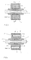
- the rotor (1) of an electrical machine shown in FIGS. 1 to 4 has a shaft (2) made of magnetic steel.
- the shaft (2) carries two essentially circular cover plates (31, 32) made of non-magnetic material, for example aluminum or die-cast aluminum, which are centered on each other and connected to the shaft (2) in a non-positive and positive manner are.
- cover plates (31, 32) Between the cover plates (31, 32), ferrite magnets (4) are radiated around the shaft (2). arranged with a rectangular cross-section.
- These are of flow guide pieces (5) with a segment segment Cross section held for this purpose on the inward and outward peripheral sides Have projections (51) which engage behind the magnets (4).
- the river guides (5) are made of layered sheets (see Figure 5).
- the cover plates (31, 32) For their attachment to the cover plates (31, 32) they are provided with holes (52) extend parallel to the shaft axis.
- the cover plates (31, 32) have corresponding ones Holes (33, 34).
- the bore (33) in a cover plate (31) is a blind hole (35) expanded diameter in the other plate (32) opposite, with holes and blind holes are arranged alternately in each cover plate (31, 32).
- a pin (6) is inserted, which on one side connects between the cover plate (31) and a flow guide (5) and on the other side in the bore (52) of the Flow guide piece (5) or in front of the cover plate (32) within the blind hole (35), so that on this side there is no connection between cover plate (32) and bolt (6) comes.
- the flow guide pieces (5) are first of all by a rotating one Edge (53) connected and are made as one-piece failure parts (sheets 54, see Figure 5) the stator bore (not shown) punched.
- the diameter of the sheets (54) is such dimensioned so that the peripheral edge (53) extends beyond the cover plates (31, 32).
- Separate Sheets (54) are formed into a rotor sheet metal stack as shown in FIG (11) connected.
- the magnets (4) are inserted into this rotor laminated core (11), then the bolts (6) are inserted.
- the cover plates (31, 32) on put on the bolts (6) and press the shaft (2).
- the resulting basic rotor body (12) is turned down to the diameter of the cover plates (31, 32) and so the circumferential Edge (53) between the flow guide pieces (5) removed. As a result, the magnets (4) free.
- a magnetically non-conductive sleeve (7) made of stainless steel is placed on the rotor base body (12) shrunk. The spaces in the rotor base body (12) are coated with casting resin (not shown) poured out.
- the rotor (101) of an electrical machine shown in FIGS. 7 to 9 has one Magnetic steel shaft (102). Between two cover plates (103) are radiating around the shaft ferrite magnets (104) are arranged with a rectangular cross section. These are from Flow guide pieces (105) are held with a circular segment-shaped cross-section, which are connected to the following inner and outer peripheral sides have projections (151) which the magnets (104) reach behind.
- the flow guide pieces (105) are made of layered sheets (see FIG. 10) manufactured.
- the flux guide pieces (105) are provided with cutouts for their attachment to the cover plates (103) (152), which have a wedge-shaped cross section and are parallel to the shaft axis extend.
- Rod-shaped holding elements (131) are guided through the cutouts (152), which are connected to the cover plates (103) in that cover plate (103) and holding elements (131) made in one piece in an injection molding process from die-cast aluminum have been.
- the flow guide pieces (105) are first of all encircling Edge (153) connected and are as one-piece failure parts (sheets 154, see Figure 10) punched out of the stator bore (not shown).
- the diameter of the sheets (154) is Dimensioned such that the peripheral edge (153) projects beyond the cover plates (103).
- Separate Sheet metal (154) becomes a rotor assembly shown in FIG (111) connected.
- the magnets (104) are inserted into this rotor package (111), then the shaft (102), the magnets (104) and the flux guide pieces (105) become one Tool (not shown) inserted and overmolded with die-cast aluminum.
- the resulting rotor base body (112) is up to the diameter of the cover plates (103) turned off and so the peripheral edge (153) between the flow guide pieces (105) away. As a result, the flux guide pieces (105) are exposed, in front of the magnets (104) thin-walled bridge made of die-cast aluminum.
- the rotor base body (112) can also a magnetically non-conductive sleeve (not shown) made of stainless steel.
Landscapes
- Engineering & Computer Science (AREA)
- Power Engineering (AREA)
- Permanent Field Magnets Of Synchronous Machinery (AREA)
Abstract
Description
In der Einzelpolwicklung wird zusätzlich zur sinusförmigen Speisespannung eine Spannung mit doppelter Frequenz induziert. Bei einer elektrischen Verbindung zwischen den Bolzen und den Deckplatten wirkt der vorbeschriebene Aufbau des Rotors aus Deckplatten und Bolzen wie ein Käfigläufer, in dem Ströme induziert werden. Dies führt zu Oberwellen und Leistungsverlusten. Zur Vermeidung dieses Phänomens könnten elektrisch nichtleitende Bolzen oder Deckplatten oder eine Isolation im Verbindungsbereich zwischen Bolzen und Deckplatten verwendet werden. Werden hierzu Kunststoffplatten, -bolzen oder -buchsen eingesetzt, wird die Festigkeit des Aufbaus geschwächt, was bei großen Drehzahlen zu einem Lockern der Bauteile führt. Hieraus würde wiederum eine zusätzliche Geräuschentwicklung entstehen. Isolationsmaterial mit größerer Festigkeit würden den Rotor verteuern. Außerdem entsteht ein in der Fertigung aufwändiger Aufbau, da viele Einzelteile verwendet werden.
- Figur 1
- einen erfindungsgemäß aufgebauten Permanentmagnet-Rotor (1) in perspektivischer Darstellung;
- Figur 2
- einen Querschnitt (B/B) durch den Rotor (1) gemäß Figur 1;
- Figur 3
- einen Längsschnitt (C/C) durch den Rotor (1);
- Figur 4
- einen Längsschnitt (A/A) durch den Rotor (1);
- Figur 5
- ein Rotorblech (54) in der Draufsicht;
- Figur 6
- die perspektivische Ansicht des Rotorblechpakets (11).
- Figur 7
- eine weitere Ausführungsform eines erfindungsgemäß aufgebauten Permanentmagnet-Rotors (101) in perspektivischer Darstellung;
- Figur 8
- einen Querschnitt (B'/B') durch den Rotor (101) gemäß Figur 7;
- Figur 9
- einen Längsschnitt (A'/A') durch den Rotor (101);
- Figur 10
- ein Rotorblech (154) in der Draufsicht;
- Figur 11
- die perspektivische Ansicht des Rotorblechpakets (111).
Claims (5)
- Permanentmagnet-Rotor (1) für eine elektrische Maschine, bei dem strahlenförmig um eine Welle (2) angeordnete Magnete (4) und dazwischen angeordnete Flussleitstücke (5) mit im wesentlichen kreissegmentförmigem Querschnitt zwischen zwei mit der Welle (2) verbundenen Deckplatten (31, 32) gehalten und mittels stabförmiger Halteelemente (Bolzen 6) fixiert werden, die durch Aussparungen (Bohrungen52) in den Flussleitstücken (5) geführt und mit den Deckplatten (31, 32) verbunden sind,
dadurch gekennzeichnet, dass die stabförmigen Elemente (Bolzen 6) jeweils nur mit einer Deckplatte verbunden sind und auf der dieser Verbindung gegenüberliegenden Seite vor der Deckplatte enden. - Permanentmagnet-Rotor (1) für eine elektrische Maschine nach Anspruch 1,
dadurch gekennzeichnet, dass die stabförmigen Elemente (Bolzen 6) wechselseitig in die Flussleitstücke ragen. - Permanentmagnet-Rotor (1) für eine elektrische Maschine nach Anspruch 1 oder 2,
dadurch gekennzeichnet, dass eine magnetisch nichtleitende Hülse (7) den aus Deckplatten (31, 32), Flussleitstücken (5) und Magneten (4) bestehenden Rotorgrundkörper (12) umgibt. - Permanentmagnet-Rotor (1) für eine elektrische Maschine nach Anspruch 3,
dadurch gekennzeichnet, dass der Raum innerhalb der Hülse (7) durch Gießharz versiegelt ist. - Permanentmagnet-Rotor (101) für eine elektrische Maschine, bei dem strahlenförmig um eine Welle (102) angeordnete Magnetblöcke (104) und dazwischen angeordnete Flussleitstücke (105) mit im wesentlichen kreissegmentförmigem Querschnitt zwischen zwei mit der Welle (102) verbundenen Deckplatten (103) gehalten und mittels stabförmiger Halteelemente (131) fixiert werden, die durch Aussparungen (152) in den Flussleitstücken (105) geführt und mit den Deckplatten (103) verbunden sind,
dadurch gekennzeichnet, dass die stabförmigen Halteelemente (131) und die Deckplatten (103) als einstückig in einem Spritzgussverfahren gefertigtes Bauteil ausgebildet sind.
Applications Claiming Priority (4)
| Application Number | Priority Date | Filing Date | Title |
|---|---|---|---|
| DE2001100717 DE10100717C1 (de) | 2001-01-10 | 2001-01-10 | Permanentmagnet-Rotor für eine elektrische Maschine |
| DE10100718 | 2001-01-10 | ||
| DE10100717 | 2001-01-10 | ||
| DE2001100718 DE10100718A1 (de) | 2001-01-10 | 2001-01-10 | Permanentmagnet-Rotor für eine elektrische Maschine |
Publications (2)
| Publication Number | Publication Date |
|---|---|
| EP1223659A2 true EP1223659A2 (de) | 2002-07-17 |
| EP1223659A3 EP1223659A3 (de) | 2004-02-04 |
Family
ID=26008196
Family Applications (1)
| Application Number | Title | Priority Date | Filing Date |
|---|---|---|---|
| EP01129584A Withdrawn EP1223659A3 (de) | 2001-01-10 | 2001-12-12 | Permanentmagnet-Rotor mit reduziertem Wirbelstromverlust |
Country Status (1)
| Country | Link |
|---|---|
| EP (1) | EP1223659A3 (de) |
Cited By (2)
| Publication number | Priority date | Publication date | Assignee | Title |
|---|---|---|---|---|
| DE10219190A1 (de) * | 2002-04-29 | 2003-11-13 | Miele & Cie | Permanentmagnet-Rotor für eine elektrische Maschine |
| EP2963775A1 (de) * | 2014-07-03 | 2016-01-06 | Gate Motor Teknolojileri Sanayi ve Ticaret A.S. | Flüssigkeitsdichter Speichenrotor |
Family Cites Families (3)
| Publication number | Priority date | Publication date | Assignee | Title |
|---|---|---|---|---|
| FR1272067A (fr) * | 1960-07-19 | 1961-09-22 | Comp Generale Electricite | Rotor d'alternateur |
| FR1313993A (fr) * | 1961-11-24 | 1963-01-04 | Comp Generale Electricite | Procédé de fabrication d'un rotor de machine électrique et machine pour la mise en oeuvre |
| JPS5970171A (ja) * | 1982-10-14 | 1984-04-20 | Fanuc Ltd | 同期電動機用回転子 |
-
2001
- 2001-12-12 EP EP01129584A patent/EP1223659A3/de not_active Withdrawn
Cited By (2)
| Publication number | Priority date | Publication date | Assignee | Title |
|---|---|---|---|---|
| DE10219190A1 (de) * | 2002-04-29 | 2003-11-13 | Miele & Cie | Permanentmagnet-Rotor für eine elektrische Maschine |
| EP2963775A1 (de) * | 2014-07-03 | 2016-01-06 | Gate Motor Teknolojileri Sanayi ve Ticaret A.S. | Flüssigkeitsdichter Speichenrotor |
Also Published As
| Publication number | Publication date |
|---|---|
| EP1223659A3 (de) | 2004-02-04 |
Similar Documents
| Publication | Publication Date | Title |
|---|---|---|
| DE10219190A1 (de) | Permanentmagnet-Rotor für eine elektrische Maschine | |
| EP0994550B1 (de) | Permanentmagneterregte Baugruppe einer elektrischen Maschine und Verfahren zu ihrer Herstellung | |
| DE2608421C3 (de) | Dauermagneterregter Innenläufer für eine Synchronmaschine | |
| DE69015606T2 (de) | Rotorbau vom radialtyp. | |
| DE69834594T2 (de) | Läufer für einen Motor oder Generator | |
| EP3292613B1 (de) | Reluktanzrotor mit zusätzlicher eigener magnetisierung | |
| EP1203436B1 (de) | Elektrische axialflussmaschine | |
| EP1495527A1 (de) | Elektrische maschine, insbesondere permanentmagnet erregte motore | |
| DE102006022836A1 (de) | Statoranordnung und Rotoranordnung für eine Transversalflußmaschine | |
| EP0729216A2 (de) | Hybriderregte Synchronmaschine | |
| EP1166423B1 (de) | Mehrpoliger, permanenterregter rotor für eine rotierende elektrische maschine und verfahren zur herstellung eines solchen rotors | |
| DE3415607A1 (de) | Rotor | |
| DE102013105851A1 (de) | Rotor für eine drehende elektrische Maschine | |
| EP2999087B1 (de) | Elektrische Maschine mit geringer magnetischer Nutstreuung | |
| DE102008018724A1 (de) | Sekundärteil für eine permanentmagneterregte Synchronmaschine | |
| DE112013000536T5 (de) | Drehende Elektromaschine mit Hybriderregung | |
| DE2953033C2 (de) | Rotor einer elektrischen Maschine mit ausgeprägten Polen | |
| DE102019212406A1 (de) | Leistungsübertragungssystem zum Erzeugen eines Stroms in einer Erregerwicklung eines Rotors einer elektrischen Maschine sowie elektrische Maschine und Kraftfahrzeug | |
| DE10100717C1 (de) | Permanentmagnet-Rotor für eine elektrische Maschine | |
| DE102020126339A1 (de) | Magnetische Einheit einer rotierenden elektrischen Maschine | |
| EP2104976B1 (de) | Elektrische maschine | |
| DE102015225523A1 (de) | Rotor einer elektrischen Maschine | |
| EP2319164A2 (de) | Rotor für eine elektrische maschine mit reduziertem rastmoment | |
| DE102010036828A1 (de) | Stator für elektrische Maschine mit überlappenden U-förmigen Kernblechen | |
| DE102021211716A1 (de) | Rotoranordnung für eine elektrische Maschine |
Legal Events
| Date | Code | Title | Description |
|---|---|---|---|
| PUAI | Public reference made under article 153(3) epc to a published international application that has entered the european phase |
Free format text: ORIGINAL CODE: 0009012 |
|
| AK | Designated contracting states |
Kind code of ref document: A2 Designated state(s): AT BE CH CY DE DK ES FI FR GB GR IE IT LI LU MC NL PT SE TR |
|
| AX | Request for extension of the european patent |
Free format text: AL;LT;LV;MK;RO;SI |
|
| RAP1 | Party data changed (applicant data changed or rights of an application transferred) |
Owner name: MIELE & CIE. KG |
|
| PUAL | Search report despatched |
Free format text: ORIGINAL CODE: 0009013 |
|
| AK | Designated contracting states |
Kind code of ref document: A3 Designated state(s): AT BE CH CY DE DK ES FI FR GB GR IE IT LI LU MC NL PT SE TR |
|
| AX | Request for extension of the european patent |
Extension state: AL LT LV MK RO SI |
|
| AKX | Designation fees paid | ||
| REG | Reference to a national code |
Ref country code: DE Ref legal event code: 8566 |
|
| STAA | Information on the status of an ep patent application or granted ep patent |
Free format text: STATUS: THE APPLICATION IS DEEMED TO BE WITHDRAWN |
|
| 18D | Application deemed to be withdrawn |
Effective date: 20040701 |