EP1223595B1 - Sectionneur à haute tension à isolation dans l'air - Google Patents
Sectionneur à haute tension à isolation dans l'air Download PDFInfo
- Publication number
- EP1223595B1 EP1223595B1 EP01403038A EP01403038A EP1223595B1 EP 1223595 B1 EP1223595 B1 EP 1223595B1 EP 01403038 A EP01403038 A EP 01403038A EP 01403038 A EP01403038 A EP 01403038A EP 1223595 B1 EP1223595 B1 EP 1223595B1
- Authority
- EP
- European Patent Office
- Prior art keywords
- contact
- angle
- disconnector
- fingers
- arm
- Prior art date
- Legal status (The legal status is an assumption and is not a legal conclusion. Google has not performed a legal analysis and makes no representation as to the accuracy of the status listed.)
- Expired - Lifetime
Links
- RYGMFSIKBFXOCR-UHFFFAOYSA-N Copper Chemical compound [Cu] RYGMFSIKBFXOCR-UHFFFAOYSA-N 0.000 description 10
- 239000010949 copper Substances 0.000 description 10
- 229910052802 copper Inorganic materials 0.000 description 10
- 230000005520 electrodynamics Effects 0.000 description 4
- XAGFODPZIPBFFR-UHFFFAOYSA-N aluminium Chemical compound [Al] XAGFODPZIPBFFR-UHFFFAOYSA-N 0.000 description 3
- 229910052782 aluminium Inorganic materials 0.000 description 3
- 238000010586 diagram Methods 0.000 description 2
- 238000006073 displacement reaction Methods 0.000 description 2
- 229910000906 Bronze Inorganic materials 0.000 description 1
- 239000010974 bronze Substances 0.000 description 1
- KUNSUQLRTQLHQQ-UHFFFAOYSA-N copper tin Chemical compound [Cu].[Sn] KUNSUQLRTQLHQQ-UHFFFAOYSA-N 0.000 description 1
- 230000007423 decrease Effects 0.000 description 1
- 230000002950 deficient Effects 0.000 description 1
- 230000000694 effects Effects 0.000 description 1
- 239000012212 insulator Substances 0.000 description 1
- 230000035515 penetration Effects 0.000 description 1
- 238000003466 welding Methods 0.000 description 1
Images



Classifications
-
- H—ELECTRICITY
- H01—ELECTRIC ELEMENTS
- H01H—ELECTRIC SWITCHES; RELAYS; SELECTORS; EMERGENCY PROTECTIVE DEVICES
- H01H31/00—Air-break switches for high tension without arc-extinguishing or arc-preventing means
- H01H31/26—Air-break switches for high tension without arc-extinguishing or arc-preventing means with movable contact that remains electrically connected to one line in open position of switch
- H01H31/28—Air-break switches for high tension without arc-extinguishing or arc-preventing means with movable contact that remains electrically connected to one line in open position of switch with angularly-movable contact
-
- H—ELECTRICITY
- H01—ELECTRIC ELEMENTS
- H01H—ELECTRIC SWITCHES; RELAYS; SELECTORS; EMERGENCY PROTECTIVE DEVICES
- H01H31/00—Air-break switches for high tension without arc-extinguishing or arc-preventing means
- H01H31/26—Air-break switches for high tension without arc-extinguishing or arc-preventing means with movable contact that remains electrically connected to one line in open position of switch
- H01H31/28—Air-break switches for high tension without arc-extinguishing or arc-preventing means with movable contact that remains electrically connected to one line in open position of switch with angularly-movable contact
- H01H2031/286—Air-break switches for high tension without arc-extinguishing or arc-preventing means with movable contact that remains electrically connected to one line in open position of switch with angularly-movable contact wherein the contact is rotatable around its own longitudinal axis
-
- H—ELECTRICITY
- H01—ELECTRIC ELEMENTS
- H01H—ELECTRIC SWITCHES; RELAYS; SELECTORS; EMERGENCY PROTECTIVE DEVICES
- H01H31/00—Air-break switches for high tension without arc-extinguishing or arc-preventing means
- H01H31/02—Details
- H01H31/023—Base and stationary contacts mounted thereon
-
- H—ELECTRICITY
- H01—ELECTRIC ELEMENTS
- H01H—ELECTRIC SWITCHES; RELAYS; SELECTORS; EMERGENCY PROTECTIVE DEVICES
- H01H31/00—Air-break switches for high tension without arc-extinguishing or arc-preventing means
- H01H31/02—Details
- H01H31/026—Movable parts and contacts mounted thereon
Definitions
- the present invention relates to a high-voltage isolating switch in the air.
- An isolator includes an arm, often called a blade, pivoting about a horizontal axis and electrically connected at one of its ends to a first connector disposed at the top of a first insulating column; the other end of the arm, the free end, comprises a contact piece, called hammer, which cooperates, in the closed position of the disconnector, with a jaw connected to a second connector disposed at the top of a second insulating column.
- the jaw consists of two parallel rows facing each other, contact pieces each formed of a curved copper blade and attached to a jaw support.
- the hammer that extends the arm at its end is a heavy and expensive piece of bronze whose section by a plane perpendicular to the axis of the arm corresponds to a circle of smaller diameter than that of the arm and which flattens on a diameter extending to join the diameter of the arm, the thickness of these two diametral extensions being 2 to 3 mm with rounded edges.
- the present invention proposes to improve certain aspects of a disconnector of this type and relates to an air-insulated high-voltage disconnector comprising a pivotable arm capable of pivoting at one of its ends, around a horizontal axis perpendicular to the axis ⁇ of the arm and also able to rotate about its own axis ⁇ , the free end of the arm carrying a contact piece called cooperating hammer, in the closed position of the disconnector, with a jaw comprising a support of jaw to which are fixed two rows facing contact fingers, characterized in that said hammer is equipped with contact pads cooperating with the contact fingers, each contact pad forming a corner, of angle ⁇ , which, when closing the disconnector, meets the corresponding row of fingers with an angle of attack ⁇ , said angle of attack ⁇ being less than 90 °.
- the angle ⁇ is of the order of 30 to 40 ° and the angle ⁇ is of the order of 60 °.
- each contact plate comprises a curved contact surface extending over an angle ⁇ , seen from the axis ⁇ of the arm, this angle ⁇ being of the order of 17 °.
- the angle ⁇ seen from the axis ⁇ of the arm, between this point of contact and the perpendicular plane the contact finger passing through the axis ⁇ , is of the order of 10 °.
- said contact fingers are fixed to the jaw support so that, in the closed position of the disconnector, the angle E between the axis ⁇ of the arm and the contact fingers is greater than 90 °.
- said fingers facing each other form between them an angle ⁇ of between 2 and 6 °.
- said contact fingers are tubular and open at both ends.
- a locking stop is fixed to a contact finger at a level above said hammer in the closed position of the disconnector.
- a disconnector comprising a pivotable arm 1 of axis ⁇ adapted to pivot in a vertical plane about a horizontal axis perpendicular to ⁇ , not shown, located to the left of the Fig. 1 .
- the unrepresented part of the arm, its pivoting control about said horizontal axis, as well as its rotation control about its axis ⁇ , as well as its support, do not form part of the invention and could, for example, be in accordance with the invention. to what is described in the patent French 2,674,985 with reference to the Fig. 1 .
- the arm 1 is tubular, as can be seen well Fig. 2 , and carries at its free end a contact piece called hammer 2.
- the hammer is composed of an aluminum support piece 3 on which two copper contact plates 4A and 4B have been fixed. This lighten the hammer.
- contact pads 4A and 4B of a particular shape, specified below, constitute the cooperating contact parts, in the closed position of the disconnector with two rows, facing each other, of contact fingers 5A and 5B of the disconnector jaw.
- a jaw support 6 which fingers 5A and 5B are attached to a jaw support 6 by a weld 7. At the jaw support 6 is fixed a stop 8 for limiting the penetration of the arm 1 between the fingers 5A and 5B of the jaw. A connector 9 is also attached to the jaw support 6. A second connector, not shown, is electrically connected to the not shown end of the arm 1, the side of its articulation about a horizontal axis.
- the jaw is supported at the upper end of a carrier insulator that is not visible, Fig. 1 , that the fitting 10 of its upper end.
- the arm 1 When closing, the arm 1 begins to pivot about its horizontal axis until it enters the jaw between the fingers 5A and 5B by making a pivoting angle of about 92 °, and then the arm 1 turns around. its axis ⁇ of 90 ° in the direction of the arrow 15, Fig. 7 . It is then that one is in a closed position, as represented on these Fig. 1 to 3 .
- the fingers 5A and 5B are fixed to the jaw support 6 so that the angle E between the axis ⁇ of the arm 1 in the closed position and the fingers 5A-5B is greater than 90 ° .
- the force F is maximum when the fingers 5A-5B are perpendicular to the axis ⁇ of the arm 1 and it decreases when this angle increases. Taking for example an angle E of 120 °, the force F is about 0.6 times that in the case where the angle E is 90 °.
- the fingers 5A and 5B being traversed in the same direction by the current, tend to get closer; thus, in the event of a short circuit, this approaching force is important and the force F results in a pulling force of the fingers of the jaw support.
- the angle E is about 120 ° and preferably between 100 and 140 °.
- the fingers 5A and 5B are not parallel but form between them a slight angle ⁇ of a few degrees of the order of 2 to 6 °.
- the fingers 5A and 5B are welded to the jaw support 6 at an angle D of 88 °, which gives an angle of 4 ° between the fingers 5A and 5B.
- a locking abutment 11 is attached to a contact finger 5B at a level above the hammer 2 in position closed disconnector.
- this stop 11 has no disadvantage since the opening begins with a 90 ° rotation of the hammer 2 in the direction of the arrow marked 12, Fig. 2 , before the pivoting of the arm 1 about a horizontal axis perpendicular to the plane of the Fig. 1 .
- the fingers 5A and 5B facing each other are fixed, as has been said, to the jaw support 6 by welding 7 with the angles E and D and have an open tubular profile at both ends so as to induce convective heat exchange in the tube.
- These fingers are aluminum and each equipped, on the face facing the opposite row, a copper contact blade 13A, 13B cooperating directly with the contact pads 4A, 4B copper hammer 2.
- This arrangement of aluminum tubular fingers just equipped with copper contact blades can greatly reduce the weight of the contact fingers compared to curved copper blades of the prior document cited in the introduction, for improved thermal performance and having sufficient rigidity fingers requiring no additional spring, as is generally necessary in the prior art where a spring is disposed between the jaw support and the curvature of the curved copper blade to provide sufficient rigidity.
- a retaining rod, respectively 14A, 14B and 14C connects, in pairs, the fingers 5A and 5B so as to limit their spacing. These retaining rods are located approximately mid-length of the contact fingers 5A, 5B.
- the arm 1 undergoes an electrodynamic force of lateral displacement in the direction of F 1 or F 2 ( Fig. 2 ), depending on whether the short-circuit occurs with a phase to the right or left of the phase on which the disconnector currently described is located.
- This displacement thanks to the spring effect of the fingers and to the retaining rods 14A, 14B and 14C does not cause contact break between the contact pieces 4A and 4B of the hammer and the contact blades 13A, 13B of the fingers.
- the Fig. 5 shows the section of a finger, for example 5B, and the Fig. 6 this same finger in section according to VI-VI of the Fig. 5 .
- FIG. 7 the position of the hammer 2 is seen when, during closure, the arm 1 having descended and having rotated about its axis ⁇ , the end of the copper contact plates 4A and 4B of the hammer arrives at contact of the copper contact blades 13A and 13B of the contact fingers 5A, 5B.
- the plates which comprise a wedge end 16 having an angle ⁇ meet the fingers with an angle of attack ⁇ .
- This angle of attack ⁇ is less than 90 ° and preferably of the order of 60 °, and makes it possible to break the ice that may have formed on the contact blades 13A, 13B.
- the angle ⁇ of the corner 16 is for example of the order of 30 to 40 °.
- this contact occurs when the distance separating the axis ⁇ from the tip of the wedge 16 is greater than the distance separating the axis ⁇ from the fingers 13A, 13B so that from that moment up to the tip of the corner 16 comes to point 18, which corresponds to a rotation of an angle ⁇ of about 10 °; the contact pads 4A, 4B push the fingers 5A, 5B acting as a spring, the contact pressure increasing to this point. Then, the contact face 19 being curved, the contact pressure remains substantially constant over a range of rotation of an angle ⁇ , Fig. 8 , about 17 ° corresponding to the angle ⁇ that covers the contact surface 19 of contact pads 4A, 4B seen from the axis ⁇ .
- This range of contact at constant pressure on an angle ⁇ of about 17 ° makes it possible to overcome the angular gaps resulting from a deficient adjustment or a loss of precision caused by the wear of the components.
Landscapes
- High-Tension Arc-Extinguishing Switches Without Spraying Means (AREA)
- Rotary Switch, Piano Key Switch, And Lever Switch (AREA)
- Arc-Extinguishing Devices That Are Switches (AREA)
- Gas-Insulated Switchgears (AREA)
- Breakers (AREA)
- Organic Insulating Materials (AREA)
- Push-Button Switches (AREA)
- Telephone Set Structure (AREA)
Description
- La présente invention concerne un sectionneur à haute tension à isolation dans l'air.
- Un sectionneur comprend notamment un bras, souvent appelé lame, pivotant autour d'un axe horizontal et relié électriquement à l'une de ses extrémités à un premier connecteur disposé au sommet d'une première colonne isolante ; l'autre extrémité du bras, l'extrémité libre, comporte une pièce de contact, appelée marteau, qui coopère, en position fermée du sectionneur, avec une mâchoire reliée à un second connecteur disposé au sommet d'une seconde colonne isolante.
- Lors de la fermeture du sectionneur, lorsque le bras pivotant s'est abaissé, il effectue ensuite autour de son axe une rotation de 90° par laquelle le marteau vient prendre contact avec les pièces de contact de la mâchoire.
- La mâchoire est constituée de deux rangées parallèles se faisant face, de pièces de contact formées chacune d'une lame de cuivre recourbée et fixée à un support de mâchoire. Le marteau qui prolonge le bras à son extrémité est une pièce en bronze, lourde et onéreuse dont la section par un plan perpendiculaire à l'axe du bras correspond à un cercle de plus petit diamètre que celui du bras et qui s'aplatit sur un diamètre en se prolongeant pour rejoindre le diamètre du bras, l'épaisseur de ces deux prolongements diamétraux étant de 2 à 3 mm à bords arrondis.
- Le brevet
français 2 674 985 - La présente invention propose d'améliorer certains aspects d'un sectionneur de ce type et a pour objet un sectionneur à haute tension à isolation dans l'air comprenant un bras pivotant apte à pivoter à l'une de ses extrémités, autour d'un axe horizontal perpendiculaire à l'axe Δ du bras et apte également à tourner autour de son propre axe Δ, l'extrémité libre du bras portant une pièce de contact appelée marteau coopérant, en position fermée du sectionneur, avec une mâchoire comportant un support de mâchoire auquel sont fixées deux rangées se faisant face de doigts de contact, caractérisé en ce que ledit marteau est équipé de plaquettes de contact coopérant avec les doigts de contact, chaque plaquette de contact formant un coin, d'angle β, qui, lors de la fermeture du sectionneur, rencontre la rangée de doigts correspondante avec un angle d'attaque α, ledit angle d'attaque α étant inférieur à 90°.
- Avantageusement, l'angle β est de l'ordre de 30 à 40° et l'angle α est de l'ordre de 60°.
- Selon une autre caractéristique, chaque plaquette de contact comporte une face de contact courbe s'étendant sur un angle δ, vu de l'axe Δ du bras, cet angle δ étant de l'ordre de 17°.
- Selon une autre caractéristique, au moment où le coin d'une plaquette de contact arrive au contact d'un dit doigt de contact, l'angle γ, vu de l'axe Δ du bras, entre ce point de contact et le plan perpendiculaire au doigt de contact passant par l'axe Δ, est de l'ordre de 10°.
- Selon une autre caractéristique, lesdits doigts de contact sont fixés au support de mâchoire de façon à ce que, en position fermée du sectionneur, l'angle E entre l'axe Δ du bras et les doigts de contact soit supérieur à 90°.
- Selon une autre caractéristique, lesdits doigts se faisant face font entre eux un angle φ compris entre 2 et 6°.
- Selon une autre caractéristique, lesdits doigts de contact sont tubulaires et ouverts à leurs deux extrémités.
- Selon une autre caractéristique, une butée de verrouillage est fixée à un doigt de contact à un niveau situé au-dessus dudit marteau en position fermée du sectionneur.
- On va maintenant donner la description d'un exemple de mise en oeuvre de l'invention en se reportant au dessin annexé dans lequel :
- La
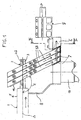
fig. 1 est une vue partielle, de gauche de lafig. 2 , d'un sectionneur selon l'invention. - La
fig. 2 est une vue en coupe selon II-II de lafig. 1 . - La
fig. 3 est une vue de dessus de lafig. 1 . - La
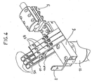
fig. 4 est une vue en perspective montrant la mâchoire du sectionneur. - La
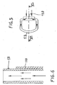
fig. 5 montre la section d'un doigt de contact de la mâchoire. - La
fig. 6 est une coupe selon VI-VI de lafig. 5 . - La
fig. 7 est un schéma illustrant l'angle d'attaque du marteau avec les doigts de contact de la mâchoire lors de la rotation du marteau au cours de la fermeture du sectionneur. - La
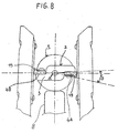
fig. 8 est un schéma illustrant la plage angulaire de contact à pression constante des doigts de la mâchoire contre le marteau. - En se référant aux
fig. 1 à 6 , on voit représenté partiellement un sectionneur comprenant un bras pivotant 1 d'axe Δ apte à pivoter dans un plan vertical autour d'un axe horizontal perpendiculaire à Δ, non représenté, situé à gauche de lafig. 1 . La partie non représentée du bras, sa commande de pivotement autour dudit axe horizontal, de même que sa commande de rotation autour de son axe Δ, ainsi que son support, ne font pas partie de l'invention et pourraient, par exemple, être conformes à ce qui est décrit dans le brevetfrançais 2 674 985 fig. 1 . - Le bras 1 est tubulaire, comme on le voit bien
fig. 2 , et porte à son extrémité libre une pièce de contact appelée marteau 2. - Le marteau est composé d'une pièce support 3 en aluminium sur laquelle ont été fixées deux plaquettes de contact en cuivre 4A et 4B. Ceci permet d'alléger le marteau.
- Ces plaquettes de contact 4A et 4B d'une forme particulière, précisée plus loin, constituent les pièces de contact coopérant, en position fermée du sectionneur avec deux rangées, se faisant face, de doigts de contacts 5A et 5B de la mâchoire du sectionneur.
- Ces doigts 5A et 5B sont fixés à un support de mâchoire 6 par une soudure 7. Au support de mâchoire 6 est fixée une butée 8 de limitation de la pénétration du bras 1 entre les doigts 5A et 5B de la mâchoire. Un connecteur 9 est également fixé au support de mâchoire 6. Un second connecteur, non représenté, est électriquement lié à l'extrémité non représentée du bras 1, du côté de son articulation autour d'un axe horizontal.
- La mâchoire est supportée à l'extrémité supérieure d'un isolateur support dont on n'aperçoit,
fig. 1 , que la ferrure 10 de son extrémité supérieure. - Sur les
fig. 1 ,2 et3 , le sectionneur est représenté en position fermée. - Lors de la fermeture, le bras 1 commence par pivoter autour de son axe horizontal jusqu'à pénétrer dans la mâchoire, entre les doigts 5A et 5B en effectuant un angle de pivotement d'environ 92°, puis ensuite le bras 1 tourne autour de son axe Δ de 90° dans le sens de la flèche 15,
fig. 7 . C'est alors que l'on est en position fermée, comme représenté sur cesfig. 1 à 3 . - Comme il est connu, compte tenu du courant qui parcourt le bras 1 et les doigts 5A et 5B, comme représenté par les flèches, non référencées, sur la
fig. 1 (ou dans le sens opposé lors de l'alternance suivante), le bras 1 subit un effort F tendant à sortir le bras de la mâchoire. Cet effort électrodynamique devient très important en cas de court-circuit entre phase et terre ou entre deux phases. - Afin de diminuer cet effort électrodynamique, les doigts 5A et 5B sont fixés au support de mâchoire 6 de façon à ce que l'angle E entre l'axe Δ du bras 1 en position fermée et les doigts 5A-5B soit supérieur à 90°.
- En effet, l'effort F est maximal lorsque les doigts 5A-5B sont perpendiculaires à l'axe Δ du bras 1 et il diminue lorsque cet angle augmente. En prenant par exemple un angle E de 120°, l'effort F est environ 0,6 fois celui dans le cas où l'angle E est de 90°.
- Par ailleurs, les doigts 5A et 5B étant parcourus dans le même sens par le courant, ont tendance à se rapprocher ; ainsi, en cas de court-circuit, cet effort de rapprochement est important et l'effort F se traduit par un effort d'arrachement des doigts du support de mâchoire.
- Ainsi, en réduisant l'effort F grâce à l'angle E supérieur à 90°, on peut donc diminuer le dimensionnement du support de mâchoire et la fixation des doigts sur ce support, ce qui permet d'alléger l'ensemble.
- Dans l'exemple représenté, l'angle E est d'environ 120° et de préférence compris entre 100 et 140°.
- Comme le montre la
fig. 2 , les doigts 5A et 5B ne sont pas parallèles mais forment entre eux un léger angle φ de quelques degrés de l'ordre de 2 à 6°. Par exemple, les doigts 5A et 5B sont soudés au support de mâchoire 6 en faisant un angle D de 88°, ce qui donne un angle de 4° entre les doigts 5A et 5B. - Ainsi, sous une contrainte de court-circuit, le déplacement vers le haut du bras 1 est limité par cette "conicité" qui maintient le marteau entre les doigts et tend à augmenter la pression de contact durant les mouvements du sectionneur sous ladite contrainte électrodynamique.
- Pour limiter encore le déplacement vers le haut du marteau entre les doigts 5A et 5B en cas de contrainte de court-circuit, une butée de verrouillage 11 est fixée à un doigt de contact 5B à un niveau situé au-dessus du marteau 2 en position fermée du sectionneur.
- Pour l'ouverture du sectionneur, cette butée 11 n'a pas d'inconvénient puisque l'ouverture commence par une rotation de 90° du marteau 2 dans le sens de la flèche repérée 12,
fig. 2 , avant le pivotement du bras 1 autour d'un axe horizontal perpendiculaire au plan de lafig. 1 . - Les doigts 5A et 5B se faisant face sont fixés, comme il a été dit, au support de mâchoire 6 par soudure 7 avec les angles E et D et ont un profil tubulaire ouvert aux deux extrémités de façon à induire un échange thermique par convection dans le tube. Ces doigts sont en aluminium et équipés, chacun, sur la face située face à la rangée d'en face, d'une lame de contact en cuivre 13A, 13B coopérant directement avec les plaquettes de contact 4A, 4B en cuivre du marteau 2.
- Cette disposition de doigts tubulaires en aluminium juste équipés de lames de contact en cuivre permet de diminuer grandement le poids des doigts de contact par rapport aux lames de cuivre recourbées du document antérieur cité en introduction, pour une performance thermique améliorée et en ayant une rigidité suffisante de doigts ne nécessitant aucun ressort supplémentaire, comme cela est généralement nécessaire dans l'art antérieur où un ressort est disposé entre le support de mâchoire et la courbure de la lame de cuivre recourbée pour lui assurer une rigidité suffisante.
- Une tige de retenue, respectivement 14A, 14B et 14C relie, par paire, les doigts 5A et 5B de façon à limiter leur écartement. Ces tiges de retenue sont situées à peu près à mi-longueur des doigts de contact 5A, 5B.
- Lors de la rotation du bras 1 dans le sens de la flèche 15,
fig. 7 , à la fin de la fermeture du sectionneur, les doigts 5A, 5B fléchissent, en formant ressort, entre les tiges 14A, 14B et 14C et l'extrémité supérieure des doigts, assurant à chaque doigt un auto-positionnement contre les plaquettes de contact en cuivre 4A et 4B du marteau 2, optimisant ainsi la ligne de contact entre le marteau et les doigts. - On peut observer qu'en cas de court-circuit entre phases, le bras 1 subit un effort électrodynamique de déplacement latéral dans le sens de F1 ou F2 (
fig. 2 ), selon que le court-circuit a lieu avec une phase située à droite ou à gauche de la phase sur laquelle se trouve le sectionneur actuellement décrit. Ce déplacement, grâce à l'effet de ressort des doigts et aux tiges de retenue 14A, 14B et 14C n'entraîne pas de rupture de contact entre les pièces de contact 4A et 4B du marteau et les lames de contact 13A, 13B des doigts. - La
fig. 5 montre la section d'un doigt, par exemple 5B, et lafig. 6 ce même doigt en coupe selon VI-VI de lafig. 5 . - En se reportant maintenant à la
fig. 7 , on voit la position du marteau 2 lorsque, au cours de la fermeture, le bras 1 ayant descendu et s'étant mis en rotation autour de son axe Δ, l'extrémité des plaquettes de contact en cuivre 4A et 4B du marteau arrive au contact des lames de contact en cuivre 13A et 13B des doigts de contact 5A, 5B. - Comme le montre cette
fig. 7 , au moment du contact, les plaquettes qui comportent une extrémité formant coin 16 ayant un angle β rencontrent les doigts avec un angle d'attaque α. Cet angle d'attaque α est inférieur à 90° et de préférence de l'ordre de 60°, et permet de briser la glace qui a pu se former sur les lames de contact 13A, 13B. L'angle β du coin 16 est par exemple de l'ordre de 30 à 40°. - Par ailleurs, ce contact se produit alors que la distance séparant l'axe Δ de la pointe du coin 16 est supérieure à la distance séparant l'axe Δ des doigts 13A, 13B de telle sorte qu'à partir de ce moment et jusqu'à ce que la pointe du coin 16 arrive au point 18, ce qui correspond à une rotation d'un angle γ d'environ 10°; les plaquettes de contact 4A, 4B repoussent les doigts 5A, 5B agissant comme ressort, la pression de contact augmentant jusqu'à ce point. Ensuite, la face de contact 19 étant courbe, la pression de contact reste sensiblement constante sur une plage de rotation d'un angle δ,
fig. 8 , d'environ 17° correspondant à l'angle δ que couvre la surface de contact 19 de plaquettes de contact 4A, 4B vu de l'axe Δ. Cette plage de contact à pression constante sur un angle δ d'environ 17° permet de s'affranchir des écarts angulaires ayant pour origine un ajustement déficient ou une perte de précision engendrée par l'usure des composants.
Claims (9)
- Sectionneur à haute tension à isolation dans l'air comprenant un bras pivotant (1) apte à pivoter à l'une de ses extrémités, autour d'un axe horizontal perpendiculaire à l'axe Δ du bras et apte également à tourner autour de son propre axe Δ, l'extrémité libre du bras portant une pièce de contact appelée marteau (2) coopérant, en position fermée du sectionneur, avec une mâchoire comportant un support de mâchoire (6) auquel sont fixées deux rangées se faisant face de doigts de contact (5A, 5B), caractérisé en ce que ledit marteau (2) est équipé de plaquettes de contact (4A, 4B) coopérant avec les doigts de contact (5A, 5B), chaque plaquette de contact (4A, 4B) formant un coin (16), d'angle β, qui, lors de la fermeture du sectionneur, rencontre la rangée de doigts correspondante avec un angle d'attaque α, ledit angle d'attaque α étant inférieur à 90°.
- Sectionneur selon la revendication 1, caractérisé en ce que l'angle β est de l'ordre de 30 à 40°.
- Sectionneur selon l'une des revendications 1 ou 2, caractérisé en ce que l'angle α est de l'ordre de 60°.
- Sectionneur selon l'une des revendications 1 à 3, caractérisé en ce que chaque plaquette de contact (4A, 4B) comporte une face de contact (19) courbe s'étendant sur un angle δ, vu de l'axe Δ du bras (1), cet angle δ étant de l'ordre de 17°.
- Sectionneur selon l'une des revendications 1 à 4, caractérisé en ce que, au moment où le coin (16) d'une plaquette de contact arrive au contact d'un dit doigt de contact, l'angle γ, vu de l'axe Δ du bras (1), entre ce point de contact et le plan perpendiculaire au doigt de contact passant par l'axe Δ, est de l'ordre de 10°.
- Sectionneur selon l'une des revendications 1 à 5, caractérisé en ce que lesdits doigts de contact (5A, 5B) sont fixés au support de mâchoire (6) de façon à ce que, en position fermée du sectionneur, l'angle E entre l'axe Δ du bras (1) et les doigts de contact soit supérieur à 90°.
- Sectionneur selon l'une des revendications 1 à 6, caractérisé en ce que lesdits doigts se faisant face font entre eux un angle φ compris entre 2 et 6°.
- Sectionneur selon l'une des revendications 1 à 7, caractérisé en ce que lesdits doigts de contact (5A, 5B) sont tubulaires et ouverts à leurs deux extrémités.
- Sectionneur selon l'une des revendications 1 à 8, caractérisé en ce qu'une butée de verrouillage (11) est fixée à un doigt de contact (5B) à un niveau situé au-dessus dudit marteau (2) en position fermée du sectionneur.
Applications Claiming Priority (2)
| Application Number | Priority Date | Filing Date | Title |
|---|---|---|---|
| FR0100424 | 2001-01-12 | ||
| FR0100424A FR2819626B1 (fr) | 2001-01-12 | 2001-01-12 | Sectionneur a haute tension a isolation dans l'air |
Publications (2)
| Publication Number | Publication Date |
|---|---|
| EP1223595A1 EP1223595A1 (fr) | 2002-07-17 |
| EP1223595B1 true EP1223595B1 (fr) | 2008-04-30 |
Family
ID=8858773
Family Applications (1)
| Application Number | Title | Priority Date | Filing Date |
|---|---|---|---|
| EP01403038A Expired - Lifetime EP1223595B1 (fr) | 2001-01-12 | 2001-11-27 | Sectionneur à haute tension à isolation dans l'air |
Country Status (10)
| Country | Link |
|---|---|
| US (1) | US6605788B2 (fr) |
| EP (1) | EP1223595B1 (fr) |
| CN (1) | CN1261957C (fr) |
| AT (1) | ATE393959T1 (fr) |
| BR (1) | BR0200021A (fr) |
| DE (1) | DE60133798T2 (fr) |
| ES (1) | ES2305040T3 (fr) |
| FR (1) | FR2819626B1 (fr) |
| MX (1) | MXPA02000412A (fr) |
| PT (1) | PT1223595E (fr) |
Families Citing this family (8)
| Publication number | Priority date | Publication date | Assignee | Title |
|---|---|---|---|---|
| US20130328458A1 (en) * | 2010-03-10 | 2013-12-12 | GE Energy Power Coversion Technology Ltd. | Rotary switches |
| DE102016214377B4 (de) * | 2016-08-03 | 2018-10-25 | Siemens Aktiengesellschaft | Kontaktarmanordnung für ein Hochspannungs-Schaltgerät und deren Verwendung |
| WO2018032303A1 (fr) * | 2016-08-16 | 2018-02-22 | 朱伯秦 | Sectionneur haute tension à double lame |
| WO2018032306A1 (fr) * | 2016-08-16 | 2018-02-22 | 朱伯秦 | Sectionneur haute tension à double lame |
| WO2018032304A1 (fr) * | 2016-08-16 | 2018-02-22 | 朱伯秦 | Sectionneur haute tension à double lame |
| CN112136198B (zh) * | 2018-05-10 | 2023-04-28 | 三菱电机株式会社 | 开关 |
| EP3734630B1 (fr) * | 2019-04-30 | 2022-01-05 | General Electric Technology GmbH | Disjoncteur á vide universel pour sectionneurs á air |
| CN112216547B (zh) * | 2020-10-27 | 2023-05-05 | 国网冀北电力有限公司检修分公司 | 一种防隔离开关提前翻转的限位复位装置和隔离开关 |
Family Cites Families (9)
| Publication number | Priority date | Publication date | Assignee | Title |
|---|---|---|---|---|
| US3388225A (en) * | 1966-09-29 | 1968-06-11 | Ite Circuit Breaker Ltd | Jaw for ice breaking switch |
| US3544742A (en) * | 1969-01-09 | 1970-12-01 | Westinghouse Electric Corp | Electric switch having improved blade construction |
| US3544741A (en) * | 1969-01-09 | 1970-12-01 | Westinghouse Electric Corp | Electric switch having improved blade construction |
| US4622443A (en) * | 1984-07-12 | 1986-11-11 | Felten & Guilleaume Energietechnik Gmbh | Single-pole load disconnecting switch arrangement in a housing |
| US5013876A (en) * | 1988-09-12 | 1991-05-07 | S&C Electric Company | Switch contacts with improved fault-closing capability |
| FR2674985B1 (fr) * | 1991-04-08 | 1996-09-06 | Gec Alsthom Engergie Inc | Sectionneur a ouverture brusque. |
| GB2286725A (en) * | 1994-02-18 | 1995-08-23 | Brian Mckean | Sequential isolating circuit breaker |
| FR2739971B1 (fr) * | 1995-10-13 | 1998-01-30 | Gec Alsthom T & D Sa | Mecanisme d'entrainement de contacts de signalisation d'un appareil electrique en particulier d'un sectionneur ou sectionneur de terre haute tension |
| FR2770929B1 (fr) * | 1997-11-13 | 2000-01-28 | Alsthom Gec | Mecanisme d'entrainement a ressort pour un appareil de commutation, en particulier un disjoncteur |
-
2001
- 2001-01-12 FR FR0100424A patent/FR2819626B1/fr not_active Expired - Fee Related
- 2001-11-27 AT AT01403038T patent/ATE393959T1/de not_active IP Right Cessation
- 2001-11-27 DE DE60133798T patent/DE60133798T2/de not_active Expired - Lifetime
- 2001-11-27 PT PT01403038T patent/PT1223595E/pt unknown
- 2001-11-27 EP EP01403038A patent/EP1223595B1/fr not_active Expired - Lifetime
- 2001-11-27 ES ES01403038T patent/ES2305040T3/es not_active Expired - Lifetime
- 2001-11-28 US US09/994,680 patent/US6605788B2/en not_active Expired - Lifetime
- 2001-12-27 CN CN01143968.8A patent/CN1261957C/zh not_active Expired - Fee Related
-
2002
- 2002-01-09 BR BR0200021-0A patent/BR0200021A/pt not_active Application Discontinuation
- 2002-01-11 MX MXPA02000412A patent/MXPA02000412A/es active IP Right Grant
Also Published As
| Publication number | Publication date |
|---|---|
| CN1261957C (zh) | 2006-06-28 |
| US20020092741A1 (en) | 2002-07-18 |
| DE60133798T2 (de) | 2009-06-25 |
| US6605788B2 (en) | 2003-08-12 |
| ES2305040T3 (es) | 2008-11-01 |
| MXPA02000412A (es) | 2004-05-21 |
| ATE393959T1 (de) | 2008-05-15 |
| BR0200021A (pt) | 2002-10-22 |
| PT1223595E (pt) | 2008-06-16 |
| DE60133798D1 (de) | 2008-06-12 |
| FR2819626A1 (fr) | 2002-07-19 |
| EP1223595A1 (fr) | 2002-07-17 |
| FR2819626B1 (fr) | 2003-02-21 |
| CN1365130A (zh) | 2002-08-21 |
Similar Documents
| Publication | Publication Date | Title |
|---|---|---|
| EP0540431B1 (fr) | Mécanisme de manoeuvre pour disjoncteur tétrapolaire | |
| FR2808117A1 (fr) | Appareillage electrique de coupure comportant une ampoule a vide et une liaison electrique flexible | |
| EP1139368B1 (fr) | Appareillage électrique de coupure multipolaire muni d'un mécanisme d'entrainement et de modules de coupure | |
| EP0161120A1 (fr) | Combiné pour coupure en charge et le sectionnement visible d'un circuit électrique | |
| EP1223595A1 (fr) | Sectionneur à haute tension à isolation dans l'air | |
| FR2807203A1 (fr) | Module de coupure comportant une ampoule a vide et des moyens de fixation, et appareillage electrique de coupure comportant un tel module | |
| EP0570264B1 (fr) | Sectionneur à ouverture verticale et colonne oscillante | |
| EP1223596B1 (fr) | Sectionneur a haute tension a isolation dans l'air | |
| EP1575067B1 (fr) | Sectionneur de terre pivotant à insertion directe et à mouvement simple | |
| EP0570265A1 (fr) | Sectionneur de terre à ouverture perpendiculaire | |
| FR2981494A1 (fr) | Conducteur leger pour appareillage electrique et appareillage electrique comportant au moins un tel conducteur | |
| EP0704872B1 (fr) | Interrupteur ou disjoncteur moyenne tension | |
| EP0591591B1 (fr) | Sectionneur à ouverture brusque | |
| CA1182153A (fr) | Dispositif de liberation des contacts mobiles de contacteurs aptes a limiter les courants de courts-circuits | |
| EP3832688B1 (fr) | Appareil de commutation électrique à contacts séparables et disjoncteur comprenant un tel appareil | |
| EP0657907B1 (fr) | Dispositif de rupture de courant d'appareil interrupteur notamment pour contacteur ou contacteur-disjoncteur | |
| FR2828004A3 (fr) | Support de contacts pour appareils de commutation basse tension avec dispositif d'entrainement | |
| EP0403329A1 (fr) | Perfectionnements aux interrupteurs à coupure automatique, notamment aux disjoncteurs et disjoncteurs différentiels | |
| EP3029703B1 (fr) | Disjoncteur, de préférence disjoncteur différentiel | |
| FR2551915A1 (fr) | Perfectionnements apportes aux coupe-circuits a manette oscillante portant une cartouche fusible et formant came pour la commande d'un circuit auxiliaire | |
| CH114783A (fr) | Interrupteur destiné à être exposé aux intempéries. | |
| FR2507002A1 (fr) | Dispositif de contact pour un interrupteur | |
| FR2783349A1 (fr) | Dispositif limitant la course d'une manette de commande d'un appareillage electrique de coupure, en cas de soudure des contacts | |
| BE706762A (fr) | ||
| BE452738A (fr) |
Legal Events
| Date | Code | Title | Description |
|---|---|---|---|
| PUAI | Public reference made under article 153(3) epc to a published international application that has entered the european phase |
Free format text: ORIGINAL CODE: 0009012 |
|
| AK | Designated contracting states |
Kind code of ref document: A1 Designated state(s): AT BE CH CY DE DK ES FI FR GB GR IE IT LI LU MC NL PT SE TR |
|
| AX | Request for extension of the european patent |
Free format text: AL;LT;LV;MK;RO;SI |
|
| 17P | Request for examination filed |
Effective date: 20030117 |
|
| AKX | Designation fees paid |
Designated state(s): AT BE CH CY DE DK ES FI FR GB GR IE IT LI LU MC NL PT SE TR |
|
| RAP1 | Party data changed (applicant data changed or rights of an application transferred) |
Owner name: AREVA T&D SA |
|
| GRAP | Despatch of communication of intention to grant a patent |
Free format text: ORIGINAL CODE: EPIDOSNIGR1 |
|
| RAP1 | Party data changed (applicant data changed or rights of an application transferred) |
Owner name: AREVA T&D SA |
|
| GRAS | Grant fee paid |
Free format text: ORIGINAL CODE: EPIDOSNIGR3 |
|
| GRAA | (expected) grant |
Free format text: ORIGINAL CODE: 0009210 |
|
| AK | Designated contracting states |
Kind code of ref document: B1 Designated state(s): AT BE CH CY DE DK ES FI FR GB GR IE IT LI LU MC NL PT SE TR |
|
| REG | Reference to a national code |
Ref country code: GB Ref legal event code: FG4D Free format text: NOT ENGLISH |
|
| REG | Reference to a national code |
Ref country code: CH Ref legal event code: EP |
|
| REG | Reference to a national code |
Ref country code: IE Ref legal event code: FG4D |
|
| REF | Corresponds to: |
Ref document number: 60133798 Country of ref document: DE Date of ref document: 20080612 Kind code of ref document: P |
|
| REG | Reference to a national code |
Ref country code: PT Ref legal event code: SC4A Free format text: AVAILABILITY OF NATIONAL TRANSLATION Effective date: 20080530 |
|
| PG25 | Lapsed in a contracting state [announced via postgrant information from national office to epo] |
Ref country code: FI Free format text: LAPSE BECAUSE OF FAILURE TO SUBMIT A TRANSLATION OF THE DESCRIPTION OR TO PAY THE FEE WITHIN THE PRESCRIBED TIME-LIMIT Effective date: 20080430 |
|
| REG | Reference to a national code |
Ref country code: ES Ref legal event code: FG2A Ref document number: 2305040 Country of ref document: ES Kind code of ref document: T3 |
|
| PG25 | Lapsed in a contracting state [announced via postgrant information from national office to epo] |
Ref country code: AT Free format text: LAPSE BECAUSE OF FAILURE TO SUBMIT A TRANSLATION OF THE DESCRIPTION OR TO PAY THE FEE WITHIN THE PRESCRIBED TIME-LIMIT Effective date: 20080430 |
|
| REG | Reference to a national code |
Ref country code: IE Ref legal event code: FD4D |
|
| PG25 | Lapsed in a contracting state [announced via postgrant information from national office to epo] |
Ref country code: SE Free format text: LAPSE BECAUSE OF FAILURE TO SUBMIT A TRANSLATION OF THE DESCRIPTION OR TO PAY THE FEE WITHIN THE PRESCRIBED TIME-LIMIT Effective date: 20080731 Ref country code: DK Free format text: LAPSE BECAUSE OF FAILURE TO SUBMIT A TRANSLATION OF THE DESCRIPTION OR TO PAY THE FEE WITHIN THE PRESCRIBED TIME-LIMIT Effective date: 20080430 Ref country code: IE Free format text: LAPSE BECAUSE OF FAILURE TO SUBMIT A TRANSLATION OF THE DESCRIPTION OR TO PAY THE FEE WITHIN THE PRESCRIBED TIME-LIMIT Effective date: 20080430 |
|
| PLBE | No opposition filed within time limit |
Free format text: ORIGINAL CODE: 0009261 |
|
| STAA | Information on the status of an ep patent application or granted ep patent |
Free format text: STATUS: NO OPPOSITION FILED WITHIN TIME LIMIT |
|
| 26N | No opposition filed |
Effective date: 20090202 |
|
| BERE | Be: lapsed |
Owner name: AREVA T&D SA Effective date: 20081130 |
|
| PG25 | Lapsed in a contracting state [announced via postgrant information from national office to epo] |
Ref country code: MC Free format text: LAPSE BECAUSE OF NON-PAYMENT OF DUE FEES Effective date: 20081130 |
|
| REG | Reference to a national code |
Ref country code: CH Ref legal event code: PL |
|
| GBPC | Gb: european patent ceased through non-payment of renewal fee |
Effective date: 20081127 |
|
| REG | Reference to a national code |
Ref country code: FR Ref legal event code: ST Effective date: 20090731 |
|
| PG25 | Lapsed in a contracting state [announced via postgrant information from national office to epo] |
Ref country code: BE Free format text: LAPSE BECAUSE OF NON-PAYMENT OF DUE FEES Effective date: 20081130 |
|
| PG25 | Lapsed in a contracting state [announced via postgrant information from national office to epo] |
Ref country code: LI Free format text: LAPSE BECAUSE OF NON-PAYMENT OF DUE FEES Effective date: 20081130 Ref country code: CH Free format text: LAPSE BECAUSE OF NON-PAYMENT OF DUE FEES Effective date: 20081130 |
|
| PG25 | Lapsed in a contracting state [announced via postgrant information from national office to epo] |
Ref country code: GB Free format text: LAPSE BECAUSE OF NON-PAYMENT OF DUE FEES Effective date: 20081127 |
|
| PG25 | Lapsed in a contracting state [announced via postgrant information from national office to epo] |
Ref country code: LU Free format text: LAPSE BECAUSE OF NON-PAYMENT OF DUE FEES Effective date: 20081127 Ref country code: CY Free format text: LAPSE BECAUSE OF FAILURE TO SUBMIT A TRANSLATION OF THE DESCRIPTION OR TO PAY THE FEE WITHIN THE PRESCRIBED TIME-LIMIT Effective date: 20080430 |
|
| PG25 | Lapsed in a contracting state [announced via postgrant information from national office to epo] |
Ref country code: TR Free format text: LAPSE BECAUSE OF FAILURE TO SUBMIT A TRANSLATION OF THE DESCRIPTION OR TO PAY THE FEE WITHIN THE PRESCRIBED TIME-LIMIT Effective date: 20080430 |
|
| PG25 | Lapsed in a contracting state [announced via postgrant information from national office to epo] |
Ref country code: GR Free format text: LAPSE BECAUSE OF FAILURE TO SUBMIT A TRANSLATION OF THE DESCRIPTION OR TO PAY THE FEE WITHIN THE PRESCRIBED TIME-LIMIT Effective date: 20080731 |
|
| PG25 | Lapsed in a contracting state [announced via postgrant information from national office to epo] |
Ref country code: FR Free format text: LAPSE BECAUSE OF NON-PAYMENT OF DUE FEES Effective date: 20081130 |
|
| REG | Reference to a national code |
Ref country code: NL Ref legal event code: TD Effective date: 20121129 |
|
| REG | Reference to a national code |
Ref country code: DE Ref legal event code: R082 Ref document number: 60133798 Country of ref document: DE Representative=s name: ZEITLER VOLPERT KANDLBINDER, DE |
|
| REG | Reference to a national code |
Ref country code: DE Ref legal event code: R082 Ref document number: 60133798 Country of ref document: DE Representative=s name: ZEITLER VOLPERT KANDLBINDER, DE Effective date: 20121211 Ref country code: DE Ref legal event code: R081 Ref document number: 60133798 Country of ref document: DE Owner name: ALSTOM TECHNOLOGY LTD., CH Free format text: FORMER OWNER: AREVA T&D S.A., PARIS, FR Effective date: 20121211 Ref country code: DE Ref legal event code: R081 Ref document number: 60133798 Country of ref document: DE Owner name: ALSTOM GRID SAS, FR Free format text: FORMER OWNER: AREVA T&D S.A., PARIS, FR Effective date: 20121211 Ref country code: DE Ref legal event code: R082 Ref document number: 60133798 Country of ref document: DE Representative=s name: ZEITLER VOLPERT KANDLBINDER PATENTANWAELTE PAR, DE Effective date: 20121211 Ref country code: DE Ref legal event code: R082 Ref document number: 60133798 Country of ref document: DE Representative=s name: ZEITLER VOLPERT KANDLBINDER PATENT- UND RECHTS, DE Effective date: 20121211 |
|
| REG | Reference to a national code |
Ref country code: DE Ref legal event code: R082 Ref document number: 60133798 Country of ref document: DE Representative=s name: ZEITLER VOLPERT KANDLBINDER, DE |
|
| REG | Reference to a national code |
Ref country code: PT Ref legal event code: PC4A Owner name: ALSTOM TECHNOLOGY LTD, CH Effective date: 20130612 |
|
| REG | Reference to a national code |
Ref country code: DE Ref legal event code: R082 Ref document number: 60133798 Country of ref document: DE Representative=s name: ZEITLER VOLPERT KANDLBINDER, DE Effective date: 20130610 Ref country code: DE Ref legal event code: R081 Ref document number: 60133798 Country of ref document: DE Owner name: ALSTOM TECHNOLOGY LTD., CH Free format text: FORMER OWNER: ALSTOM GRID SAS, PARIS, FR Effective date: 20130610 Ref country code: DE Ref legal event code: R082 Ref document number: 60133798 Country of ref document: DE Representative=s name: ZEITLER VOLPERT KANDLBINDER PATENTANWAELTE PAR, DE Effective date: 20130610 Ref country code: DE Ref legal event code: R082 Ref document number: 60133798 Country of ref document: DE Representative=s name: ZEITLER VOLPERT KANDLBINDER PATENT- UND RECHTS, DE Effective date: 20130610 |
|
| REG | Reference to a national code |
Ref country code: ES Ref legal event code: PC2A Owner name: ALSTOM GRID SAS Effective date: 20130904 |
|
| REG | Reference to a national code |
Ref country code: ES Ref legal event code: PC2A Owner name: ALSTOM TECHNOLOGY LTD Effective date: 20131015 |
|
| PGFP | Annual fee paid to national office [announced via postgrant information from national office to epo] |
Ref country code: DE Payment date: 20141113 Year of fee payment: 14 Ref country code: ES Payment date: 20141124 Year of fee payment: 14 |
|
| PGFP | Annual fee paid to national office [announced via postgrant information from national office to epo] |
Ref country code: IT Payment date: 20141113 Year of fee payment: 14 |
|
| REG | Reference to a national code |
Ref country code: NL Ref legal event code: SD Effective date: 20150610 Ref country code: NL Ref legal event code: TD Effective date: 20150610 |
|
| PGFP | Annual fee paid to national office [announced via postgrant information from national office to epo] |
Ref country code: NL Payment date: 20151014 Year of fee payment: 15 Ref country code: PT Payment date: 20151019 Year of fee payment: 15 |
|
| REG | Reference to a national code |
Ref country code: DE Ref legal event code: R119 Ref document number: 60133798 Country of ref document: DE |
|
| PG25 | Lapsed in a contracting state [announced via postgrant information from national office to epo] |
Ref country code: IT Free format text: LAPSE BECAUSE OF NON-PAYMENT OF DUE FEES Effective date: 20151127 |
|
| PG25 | Lapsed in a contracting state [announced via postgrant information from national office to epo] |
Ref country code: DE Free format text: LAPSE BECAUSE OF NON-PAYMENT OF DUE FEES Effective date: 20160601 |
|
| PG25 | Lapsed in a contracting state [announced via postgrant information from national office to epo] |
Ref country code: ES Free format text: LAPSE BECAUSE OF NON-PAYMENT OF DUE FEES Effective date: 20151128 |
|
| REG | Reference to a national code |
Ref country code: NL Ref legal event code: MM Effective date: 20161201 |
|
| PG25 | Lapsed in a contracting state [announced via postgrant information from national office to epo] |
Ref country code: PT Free format text: LAPSE BECAUSE OF NON-PAYMENT OF DUE FEES Effective date: 20170529 |
|
| PG25 | Lapsed in a contracting state [announced via postgrant information from national office to epo] |
Ref country code: NL Free format text: LAPSE BECAUSE OF NON-PAYMENT OF DUE FEES Effective date: 20161201 |
|
| REG | Reference to a national code |
Ref country code: ES Ref legal event code: FD2A Effective date: 20180705 |