EP1223486B1 - Method of controlling the movement of a mass moved by a pressurised hydraulic cylinder - Google Patents
Method of controlling the movement of a mass moved by a pressurised hydraulic cylinder Download PDFInfo
- Publication number
- EP1223486B1 EP1223486B1 EP01129462A EP01129462A EP1223486B1 EP 1223486 B1 EP1223486 B1 EP 1223486B1 EP 01129462 A EP01129462 A EP 01129462A EP 01129462 A EP01129462 A EP 01129462A EP 1223486 B1 EP1223486 B1 EP 1223486B1
- Authority
- EP
- European Patent Office
- Prior art keywords
- piston rod
- mass
- cylinder
- acceleration
- dependent
- Prior art date
- Legal status (The legal status is an assumption and is not a legal conclusion. Google has not performed a legal analysis and makes no representation as to the accuracy of the status listed.)
- Expired - Lifetime
Links
Images
Classifications
-
- B—PERFORMING OPERATIONS; TRANSPORTING
- B29—WORKING OF PLASTICS; WORKING OF SUBSTANCES IN A PLASTIC STATE IN GENERAL
- B29C—SHAPING OR JOINING OF PLASTICS; SHAPING OF MATERIAL IN A PLASTIC STATE, NOT OTHERWISE PROVIDED FOR; AFTER-TREATMENT OF THE SHAPED PRODUCTS, e.g. REPAIRING
- B29C45/00—Injection moulding, i.e. forcing the required volume of moulding material through a nozzle into a closed mould; Apparatus therefor
- B29C45/17—Component parts, details or accessories; Auxiliary operations
- B29C45/64—Mould opening, closing or clamping devices
- B29C45/68—Mould opening, closing or clamping devices hydro-mechanical
- B29C45/681—Mould opening, closing or clamping devices hydro-mechanical using a toggle mechanism as mould clamping device
-
- B—PERFORMING OPERATIONS; TRANSPORTING
- B29—WORKING OF PLASTICS; WORKING OF SUBSTANCES IN A PLASTIC STATE IN GENERAL
- B29C—SHAPING OR JOINING OF PLASTICS; SHAPING OF MATERIAL IN A PLASTIC STATE, NOT OTHERWISE PROVIDED FOR; AFTER-TREATMENT OF THE SHAPED PRODUCTS, e.g. REPAIRING
- B29C45/00—Injection moulding, i.e. forcing the required volume of moulding material through a nozzle into a closed mould; Apparatus therefor
- B29C45/17—Component parts, details or accessories; Auxiliary operations
- B29C45/76—Measuring, controlling or regulating
- B29C45/82—Hydraulic or pneumatic circuits
-
- F—MECHANICAL ENGINEERING; LIGHTING; HEATING; WEAPONS; BLASTING
- F15—FLUID-PRESSURE ACTUATORS; HYDRAULICS OR PNEUMATICS IN GENERAL
- F15B—SYSTEMS ACTING BY MEANS OF FLUIDS IN GENERAL; FLUID-PRESSURE ACTUATORS, e.g. SERVOMOTORS; DETAILS OF FLUID-PRESSURE SYSTEMS, NOT OTHERWISE PROVIDED FOR
- F15B9/00—Servomotors with follow-up action, e.g. obtained by feed-back control, i.e. in which the position of the actuated member conforms with that of the controlling member
- F15B9/02—Servomotors with follow-up action, e.g. obtained by feed-back control, i.e. in which the position of the actuated member conforms with that of the controlling member with servomotors of the reciprocatable or oscillatable type
- F15B9/08—Servomotors with follow-up action, e.g. obtained by feed-back control, i.e. in which the position of the actuated member conforms with that of the controlling member with servomotors of the reciprocatable or oscillatable type controlled by valves affecting the fluid feed or the fluid outlet of the servomotor
- F15B9/09—Servomotors with follow-up action, e.g. obtained by feed-back control, i.e. in which the position of the actuated member conforms with that of the controlling member with servomotors of the reciprocatable or oscillatable type controlled by valves affecting the fluid feed or the fluid outlet of the servomotor with electrical control means
-
- G—PHYSICS
- G05—CONTROLLING; REGULATING
- G05B—CONTROL OR REGULATING SYSTEMS IN GENERAL; FUNCTIONAL ELEMENTS OF SUCH SYSTEMS; MONITORING OR TESTING ARRANGEMENTS FOR SUCH SYSTEMS OR ELEMENTS
- G05B19/00—Programme-control systems
- G05B19/02—Programme-control systems electric
- G05B19/18—Numerical control [NC], i.e. automatically operating machines, in particular machine tools, e.g. in a manufacturing environment, so as to execute positioning, movement or co-ordinated operations by means of programme data in numerical form
- G05B19/19—Numerical control [NC], i.e. automatically operating machines, in particular machine tools, e.g. in a manufacturing environment, so as to execute positioning, movement or co-ordinated operations by means of programme data in numerical form characterised by positioning or contouring control systems, e.g. to control position from one programmed point to another or to control movement along a programmed continuous path
- G05B19/21—Numerical control [NC], i.e. automatically operating machines, in particular machine tools, e.g. in a manufacturing environment, so as to execute positioning, movement or co-ordinated operations by means of programme data in numerical form characterised by positioning or contouring control systems, e.g. to control position from one programmed point to another or to control movement along a programmed continuous path using an incremental digital measuring device
- G05B19/23—Numerical control [NC], i.e. automatically operating machines, in particular machine tools, e.g. in a manufacturing environment, so as to execute positioning, movement or co-ordinated operations by means of programme data in numerical form characterised by positioning or contouring control systems, e.g. to control position from one programmed point to another or to control movement along a programmed continuous path using an incremental digital measuring device for point-to-point control
-
- G—PHYSICS
- G05—CONTROLLING; REGULATING
- G05B—CONTROL OR REGULATING SYSTEMS IN GENERAL; FUNCTIONAL ELEMENTS OF SUCH SYSTEMS; MONITORING OR TESTING ARRANGEMENTS FOR SUCH SYSTEMS OR ELEMENTS
- G05B19/00—Programme-control systems
- G05B19/43—Programme-control systems fluidic
- G05B19/46—Programme-control systems fluidic hydraulic
-
- B—PERFORMING OPERATIONS; TRANSPORTING
- B29—WORKING OF PLASTICS; WORKING OF SUBSTANCES IN A PLASTIC STATE IN GENERAL
- B29C—SHAPING OR JOINING OF PLASTICS; SHAPING OF MATERIAL IN A PLASTIC STATE, NOT OTHERWISE PROVIDED FOR; AFTER-TREATMENT OF THE SHAPED PRODUCTS, e.g. REPAIRING
- B29C2945/00—Indexing scheme relating to injection moulding, i.e. forcing the required volume of moulding material through a nozzle into a closed mould
- B29C2945/76—Measuring, controlling or regulating
- B29C2945/76003—Measured parameter
- B29C2945/76083—Position
-
- B—PERFORMING OPERATIONS; TRANSPORTING
- B29—WORKING OF PLASTICS; WORKING OF SUBSTANCES IN A PLASTIC STATE IN GENERAL
- B29C—SHAPING OR JOINING OF PLASTICS; SHAPING OF MATERIAL IN A PLASTIC STATE, NOT OTHERWISE PROVIDED FOR; AFTER-TREATMENT OF THE SHAPED PRODUCTS, e.g. REPAIRING
- B29C2945/00—Indexing scheme relating to injection moulding, i.e. forcing the required volume of moulding material through a nozzle into a closed mould
- B29C2945/76—Measuring, controlling or regulating
- B29C2945/76003—Measured parameter
- B29C2945/7611—Velocity
- B29C2945/76113—Velocity linear movement
- B29C2945/76117—Velocity linear movement derivative, change thereof
-
- B—PERFORMING OPERATIONS; TRANSPORTING
- B29—WORKING OF PLASTICS; WORKING OF SUBSTANCES IN A PLASTIC STATE IN GENERAL
- B29C—SHAPING OR JOINING OF PLASTICS; SHAPING OF MATERIAL IN A PLASTIC STATE, NOT OTHERWISE PROVIDED FOR; AFTER-TREATMENT OF THE SHAPED PRODUCTS, e.g. REPAIRING
- B29C2945/00—Indexing scheme relating to injection moulding, i.e. forcing the required volume of moulding material through a nozzle into a closed mould
- B29C2945/76—Measuring, controlling or regulating
- B29C2945/76177—Location of measurement
- B29C2945/76224—Closure or clamping unit
- B29C2945/7623—Closure or clamping unit clamping or closing drive means
-
- G—PHYSICS
- G05—CONTROLLING; REGULATING
- G05B—CONTROL OR REGULATING SYSTEMS IN GENERAL; FUNCTIONAL ELEMENTS OF SUCH SYSTEMS; MONITORING OR TESTING ARRANGEMENTS FOR SUCH SYSTEMS OR ELEMENTS
- G05B2219/00—Program-control systems
- G05B2219/30—Nc systems
- G05B2219/41—Servomotor, servo controller till figures
- G05B2219/41309—Hydraulic or pneumatic drive
-
- G—PHYSICS
- G05—CONTROLLING; REGULATING
- G05B—CONTROL OR REGULATING SYSTEMS IN GENERAL; FUNCTIONAL ELEMENTS OF SUCH SYSTEMS; MONITORING OR TESTING ARRANGEMENTS FOR SUCH SYSTEMS OR ELEMENTS
- G05B2219/00—Program-control systems
- G05B2219/30—Nc systems
- G05B2219/42—Servomotor, servo controller kind till VSS
- G05B2219/42041—Adaptive pd
Definitions
- the invention relates to a method for regulating the movement one of a pressurized hydraulic Cylinder moving mass, via a gearbox with stroke-dependent Translation, in particular via a toggle lever arrangement, connected to the piston rod of the cylinder, according to The preamble of claim 1.
- a control method is known from EP 0605021 A.
- a transmission Located between the piston rod of a hydraulic Cylinder and a mass to be moved is a transmission, so is the size of the resultant on the piston rod resulting Measure the product of the mass to be moved and the square the transmission ratio of the transmission.
- the natural frequency of the cylinder, the transmission and the moving Mass formed system is characterized by that in the chambers of the Cylinder trapped oil volume and the resulting Mass determined.
- gearboxes whose translation is independent from the position of the mass to be moved, such. B. at Gear drives or simple lever gears, changes the natural frequency only as a function of the over the Cylinder stroke changing oil volume.
- the gear ratio changes additionally depending on the position of the moving Dimensions.
- the natural frequency is not only in this case from the stroke-dependent change in the cylinder trapped Oil volume but also of which is with the position the mass to be moved changing transmission ratio of Gearbox dependent. Is the mass to be moved in a middle range between their end positions, is the natural frequency of the cylinder, the transmission and the moving Mass made system low. Is that too moving mass, however, near the end positions, the rise Natural frequency very strong. The natural frequency increases the stronger, the more the mass of the respective end position approaches. For the regulation of the movement of such Systems affects the in the end positions of the moving Mass very high natural frequency disadvantageous. Because the parameters the control device must be set so that no instability even at the highest natural frequency This will result in areas of low natural frequency to a noticeable loss of momentum.
- the invention has for its object to provide a method of specify the type mentioned above, which allows the parameters the control device according to the areas lower Set natural frequency without being in areas with high natural frequency instabilities occur.
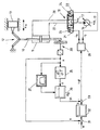
- the piston rod 10 of a hydraulic cylinder 11 moves via a knee lever assembly 12 a in a sliding joint Guided mass 13.
- the toggle lever assembly 12 is itself to a transmission with stroke-dependent translation whose Gear ratio of the position of the mass 13 dependent is.
- Such transmissions are used in injection molding machines, because their kinematic speed course favorable for closing and opening the injection molding tools.
- at the mass 13 is a tool half of a Injection mold, which is shown here only schematically is.
- the position of the mass 13 is denoted by xm.
- An in the drawing shown as a variable displacement pump 16 promotes Pressure medium from a tank 17.
- An electro-magnetically actuated hydraulic valve 18 controls the pressure medium supply to the chambers of the cylinder 11.
- An amplifier 20 sets a Control voltage ust into currents ia and ib.
- the spool of the Valve 18 is in the absence of control by springs 23 and 24 held in its middle position.
- the sign of the Control voltage ust determines whether the magnet 21 or the magnet 22 is energized.
- the amount of control voltage ust determines the size of the deflection of the spool valve Valve 18.
- the deflection of the spool determines the Opening cross section of the valve 18 and thus the speed, with the piston rod 10 on or extends. Is the Control voltage ust positive, the magnet 21 with a Current ia applied to its height by the amount of control voltage ust is determined.
- This current directs the spool of the valve 18 so that pressure fluid from the pump 16 via a line 27 into the lower chamber of the cylinder eleventh flows.
- the piston rod 10 extends and moves the mass 13th over the knee lever assembly 12 to the right. From the top Chamber of the cylinder 10, pressure medium is displaced and flows via a line 28 and the valve 18 to the tank 17 back. If the control voltage ust negative, the magnet 22 with a current ib charged, whose amount by the amount of Control voltage ust is determined. This current directs the spool of the valve 18 so that pressure fluid from the Pump 16 via line 28 into the upper chamber of the cylinder 11 flows. The piston rod 10 retracts and moves the Mass 13 on the knee lever assembly 12 to the left. From the lower chamber of the cylinder 10, pressure medium is displaced and flows via the line 27 and the valve 18 to the tank 17th back.
- An only schematically illustrated displacement sensor 30 detects the position of the piston rod 10.
- the position of the piston rod 10 is denoted by x in the following. Since there is a fixed relationship between the position xm of the mass 13 and the position x of the piston rod 10 via the toggle lever arrangement 12, it is not necessary to provide an additional displacement sensor for the position xm of the mass 13, but it suffices to determine the position x of the piston rod 10 and to calculate from this the position of the mass xm.
- a digital displacement sensor is preferably used in order to reduce the influence of noise signals superimposed on the useful signal in the temporal derivative of the position signal.
- a comparison device 31 forms the difference between a reference variable w for the position of the piston rod 10 and the position x serving as the actual position of the piston rod.
- the output signal of the comparator 31 is fed to a controller 32 with P-behavior as a control deviation.
- a logic circuit 33 superimposes an auxiliary quantity yh on the output signal y of the controller 32.
- the logic circuit 33 outputs the control voltage ust, which determines the direction and amount of the speed at which the piston rod 10 of the cylinder 11 moves.
- a differentiating element 35 forms by twice the time derivative of the position x of the piston rod 10 is a signal , which is a measure of the acceleration of the piston rod 10.
- the differentiating element 35 is followed by a P-element 36 with a controllable amplification factor.
- the amplification factor of the P-element 36 is designated KB.
- the adjustment of the gain factor KB is effected by the output signal of a function generator 37, which converts the position x of the piston rod 10 into a trapezoidal function.
- the trapezoidal function approximates the relationship between the natural frequency of the system consisting of the cylinder 11, the transmission 12 and the mass 23 to be moved and the position of the mass 13 or piston rod 10 to be moved. Unlike saving the exact profile, only four points need to be stored for the trapezoidal function. This measure leads to a significant reduction in the required storage space.
- the function generator 37 ensures that the gain factor KB is small in the regions near the end positions of the mass 13 to be moved and large in the region lying between the end positions. This means that the auxiliary quantity yh, which is subtracted from the output variable y of the controller 32, is effective only in the middle region between the end positions and then subsequently reduced to the end positions until it is virtually no longer effective in the end positions.
- the inventive method is not only in connection with a position control for the piston rod 10 - as in the figure shown - used, but also for a Control of the speed with which the piston rod 10 is moved. This is the case when the signal connection between the controller 32 and the logic circuit 33rd is separated and the logic circuit 33 instead of the Output voltage of the controller 32, an external control voltage as a measure of the speed with which the piston rod 10th the cylinder 11 is to be moved, is supplied.
- the inventive method can also be used for drives use in which the control of the cylinder supplied Pressure medium through a pure pump drive with adjustable Volumetric flow takes place, so that the throttle losses generating valve between the pump and the cylinder omitted can.
- the control of the flow rate through the delivery volume of the pump and / or by the control of Speed of the motor driving the pump can be used for drives use in which the control of the cylinder supplied Pressure medium through a pure pump drive with adjustable Volumetric flow takes place, so that the throttle losses generating valve between the pump and the cylinder omitted can.
- the process according to the invention can not only be advantageous for the regulation of the movement of toggle arrangements in plastic machines - as in the above embodiment described - but also to regulate the movement of toggle assemblies in presses.
- General is the inventive method always applicable when a mass via a transmission with stroke-dependent translation is driven by a hydraulic cylinder.
Abstract
Description
Die Erfindung betrifft ein Verfahren zur Regelung der Bewegung einer von einem druckmittelbeaufschlagten hydraulischen Zylinder bewegbaren Masse, die über ein Getriebe mit hubabhängiger Übersetzung, insbesondere über eine Kniehebelanordnung, mit der Kolbenstange des Zylinders verbunden ist, gemäß dem Oberbegriff des Anspruchs 1. Ein derartiges Regelungs verfahren ist aus EP 0605021 A bekannt.The invention relates to a method for regulating the movement one of a pressurized hydraulic Cylinder moving mass, via a gearbox with stroke-dependent Translation, in particular via a toggle lever arrangement, connected to the piston rod of the cylinder, according to The preamble of claim 1. Such a control method is known from EP 0605021 A.
Systeme mit einer Masse, die von einem druckmittelbeaufschlagten hydraulischen Zylinder bewegt wird, wobei zwischen der Kolbenstange des Zylinders und der Masse ein Getriebe mit hubabhängiger Übersetzung in Form einer Kniehebelanordnung vorgesehen ist, werden u. a. in Spritzgießmaschinen eingesetzt, insbesondere zum Bewegen von Werkzeugen beim Schließen und Öffnen der Spritzgießformen.Systems with a mass of a pressurized medium hydraulic cylinder is moved, taking between the piston rod of the cylinder and the mass a gearbox with stroke-dependent translation in the form of a toggle lever arrangement is provided, u. a. used in injection molding machines, especially for moving tools when closing and opening the injection molds.
Befindet sich zwischen der Kolbenstange eines hydraulischen Zylinders und einer zu bewegenden Masse ein Getriebe, so ist die Größe der auf die Kolbenstange wirkenden resultierenden Masse das Produkt aus der zu bewegenden Masse und dem Quadrat des Übersetzungsverhältnisses des Getriebes. Die Eigenfrequenz des aus dem Zylinder, dem Getriebe und der zu bewegenden Masse gebildeten Systems ist durch das in den Kammern des Zylinders eingeschlossene Ölvolumen und die resultierende Masse bestimmt. Bei Getrieben, deren Übersetzung unabhängig von der Position der zu bewegenden Masse ist, wie z. B. bei Zahnradgetrieben oder einfachen Hebelgetrieben, ändert sich die Eigenfrequenz nur in Abhängigkeit von dem sich über den Zylinderhub ändernden Ölvolumen. Bei einem Getriebe mit hubabhängiger Übersetzung dagegen, wie z. B. bei einem Kniehebelantrieb, ändert sich das Übersetzungsverhältnis zusätzlich in Abhängigkeit von der Position der zu bewegenden Masse. Die Eigenfrequenz ist in diesem Fall nicht mehr nur von der hubabhängigen Änderung des im Zylinder eingeschlossenen Ölvolumens sondern auch von dem sich mit der Position der zu bewegenden Masse ändernden Übersetzungsverhältnis des Getriebes abhängig. Befindet sich die zu bewegende Masse in einem Mittelbereich zwischen ihren Endlagen, ist die Eigenfrequenz des aus dem Zylinder, dem Getriebe und der zu bewegenden Masse gebildeten Systems niedrig. Befindet sich die zu bewegende Masse dagegen in der Nähe der Endlagen, steigt die Eigenfrequenz sehr stark an. Dabei steigt die Eigenfrequenz um so stärker an, je mehr sich die Masse der jeweiligen Endlage nähert. Für die Regelung der Bewegung von derartigen Systemen wirkt sich die in den Endlagen der zu bewegenden Masse sehr hohe Eigenfrequenz nachteilig aus. Da die Parameter der Regeleinrichtung so eingestellt werden müssen, daß sich auch bei der höchsten Eigenfrequenz keine Instabilität einstellt, führt dies in Bereichen mit niedriger Eigenfrequenz zu einem spürbaren Dynamikverlust.Located between the piston rod of a hydraulic Cylinder and a mass to be moved is a transmission, so is the size of the resultant on the piston rod resulting Measure the product of the mass to be moved and the square the transmission ratio of the transmission. The natural frequency of the cylinder, the transmission and the moving Mass formed system is characterized by that in the chambers of the Cylinder trapped oil volume and the resulting Mass determined. In gearboxes whose translation is independent from the position of the mass to be moved, such. B. at Gear drives or simple lever gears, changes the natural frequency only as a function of the over the Cylinder stroke changing oil volume. In a transmission with stroke-dependent Translation against it, such as B. in a toggle drive, the gear ratio changes additionally depending on the position of the moving Dimensions. The natural frequency is not only in this case from the stroke-dependent change in the cylinder trapped Oil volume but also of which is with the position the mass to be moved changing transmission ratio of Gearbox dependent. Is the mass to be moved in a middle range between their end positions, is the natural frequency of the cylinder, the transmission and the moving Mass made system low. Is that too moving mass, however, near the end positions, the rise Natural frequency very strong. The natural frequency increases the stronger, the more the mass of the respective end position approaches. For the regulation of the movement of such Systems affects the in the end positions of the moving Mass very high natural frequency disadvantageous. Because the parameters the control device must be set so that no instability even at the highest natural frequency This will result in areas of low natural frequency to a noticeable loss of momentum.
Der Erfindung liegt die Aufgabe zugrunde, ein Verfahren der eingangs genannten Art anzugeben, das es erlaubt, die Parameter der Regeleinrichtung entsprechend den Bereichen niedriger Eigenfrequenz einzustellen, ohne daß in Bereichen mit hoher Eigenfrequenz Instabilitäten auftreten. The invention has for its object to provide a method of specify the type mentioned above, which allows the parameters the control device according to the areas lower Set natural frequency without being in areas with high natural frequency instabilities occur.
Diese Aufgabe wird durch die im Anspruch 1 gekennzeichneten Merkmale gelöst. Da in Bereichen mit hoher Eigenfrequenz die Rückführung des Beschleunigungssignals praktisch nicht wirksam ist, ist es zulässig, in Bereichen mit niedriger Eigenfrequenz die Parameter der Regeleinrichtung dieser Frequenz entsprechend zu optimieren, wodurch es in den Bereichen mit niedriger Eigenfrequenz nicht zu Dynamikverlusten kommt.This object is characterized by that defined in claim 1 Characteristics solved. Since in areas with high natural frequency the Return of the acceleration signal practically not effective is, it is permissible in areas with low natural frequency the parameters of the control device of this frequency to optimize accordingly, making it in the areas with low natural frequency does not lead to dynamic losses.
Vorteilhafte Weiterbildungen der Erfindung sind in den Unteransprüchen gekennzeichnet. Da zwischen der Position der bewegbaren Masse und der Position der Kolbenstange ein fester Zusammenhang besteht, ist es ausreichend, für die Wichtung des Beschleunigungssignals anstelle der Position der bewegbaren Masse die Position der Kolbenstange zu erfassen. Der Rechenaufwand läßt sich verringern, wenn der Zusammenhang zwischen der Position der bewegbaren Masse und dem Faktor für die Wichtung des Beschleunigungssignals durch eine Trapezfunktion angenähert wird. In diesem Fall brauchen anstelle des den Zusammenhang zwischen der Position der Masse und der Eigenfrequenz des aus dem Zylinder, dem Getriebe und der zu bewegenden Masse gebildeten Systems beschreibenden exakten Profils nur vier Punkte abgespeichert zu werden. Die Beschleunigung der Kolbenstange läßt sich auf einfache Weise dadurch ermitteln, daß man ihre Position zwei Mal nach der Zeit ableitet. Digitale Wegsensoren sind hierbei gegenüber analogen Wegsensoren von Vorteil, da bei ihnen das Problem der zeitlichen Ableitung von dem Positionssignal überlagerten Rauschsignalen nur in geringem Maß auftritt. Advantageous developments of the invention are in the dependent claims characterized. Because between the position of the movable Mass and the position of the piston rod a solid Context, it is sufficient for the weighting the acceleration signal instead of the position of the movable Mass to detect the position of the piston rod. Of the Computing effort can be reduced if the context between the position of the movable mass and the factor for the weighting of the acceleration signal by a trapezoidal function is approximated. In this case need instead of the relationship between the position of the mass and the Natural frequency of the out of the cylinder, the transmission and the too moving mass formed system describing exact Profile only four points to be saved. The acceleration the piston rod can be easily By determining their position twice after the Time derives. Digital displacement sensors are opposite analog way sensors advantageous because with them the problem the time derivative of the position signal superimposed Noise occurs only to a small degree.
Die Erfindung wird im folgenden mit ihren weiteren Einzelheiten anhand eines in der einzigen Zeichnung dargestellten Ausführungsbeispiels näher erläutert. Die Zeichnung zeigt einen Kniehebelantrieb und seine Ansteuerung in schematischer Darstellung.The invention will be described below with further details based on one shown in the single drawing Embodiment explained in more detail. The drawing shows a toggle lever drive and its control in schematic Presentation.
Die Kolbenstange 10 eines hydraulischen Zylinders 11 bewegt
über eine Kniehebelanordnung 12 eine in einem Schubgelenk
geführte Masse 13. Bei der Kniehebelanordnung 12 handelt es
sich um ein Getriebe mit hubabhängiger Übersetzung, dessen
Übersetzungsverhältnis von der Position der Masse 13 abhängig
ist. Derartige Getriebe werden in Spritzgießmaschinen eingesetzt,
weil ihr kinematischer Geschwindigkeitsverlauf günstig
für das Schließen und Öffnen der Spritzgießwerkzeuge ist. Bei
der Masse 13 handelt es sich um eine Werkzeughälfte eines
Spritzgießwerkzeugs, die hier nur schematisch dargestellt
ist. Die Position der Masse 13 ist mit xm bezeichnet. Eine in
der Zeichnung als Verstellpumpe dargestellte Pumpe 16 fördert
Druckmittel aus einem Tank 17. Ein elektro-magnetisch betätigtes
hydraulisches Ventil 18 steuert die Druckmittelzufuhr
zu den Kammern des Zylinders 11. Ein Verstärker 20 setzt eine
Steuerspannung ust in Ströme ia und ib um. Die Ströme ia und
ib sind Magneten 21 bzw. 22 zugeführt. Der Steuerschieber des
Ventils 18 ist bei fehlender Ansteuerung durch Federn 23 und
24 in seiner Mittelstellung gehalten. Das Vorzeichen der
Steuerspannung ust bestimmt, ob der Magnet 21 oder der Magnet
22 mit Strom beaufschlagt wird. Der Betrag der Steuerspannung
ust bestimmt die Größe der Auslenkung des Steuerschiebers des
Ventils 18. Die Auslenkung des Steuerschiebers bestimmt den
Öffnungsquerschnitt des Ventils 18 und damit die Geschwindigkeit,
mit der die Kolbenstange 10 ein- oder ausfährt. Ist die
Steuerspannung ust positiv, wird der Magnet 21 mit einem
Strom ia beaufschlagt, dessen Höhe durch den Betrag der Steuerspannung
ust bestimmt ist. Dieser Strom lenkt den Steuerschieber
des Ventils 18 so aus, daß Druckmittel von der Pumpe
16 über eine Leitung 27 in die untere Kammer des Zylinders 11
fließt. Die Kolbenstange 10 fährt aus und bewegt die Masse 13
über die Kniehebelanordnung 12 nach rechts. Aus der oberen
Kammer des Zylinders 10 wird Druckmittel verdrängt und fließt
über eine Leitung 28 und das Ventil 18 zum Tank 17 zurück.
Ist die Steuerspannung ust negativ, wird der Magnet 22 mit
einem Strom ib beaufschlagt, dessen Höhe durch den Betrag der
Steuerspannung ust bestimmt ist. Dieser Strom lenkt den Steuerschieber
des Ventils 18 so aus, daß Druckmittel von der
Pumpe 16 über die Leitung 28 in die obere Kammer des Zylinders
11 fließt. Die Kolbenstange 10 fährt ein und bewegt die
Masse 13 über die Kniehebelanordnung 12 nach links. Aus der
unteren Kammer des Zylinders 10 wird Druckmittel verdrängt
und fließt über die Leitung 27 und das Ventil 18 zum Tank 17
zurück.The
Ein nur schematisch dargestellter Wegsensor 30 erfaßt die
Position der Kolbenstange 10. Die Position der Kolbenstange
10 ist im folgenden mit x bezeichnet. Da über die Kniehebelanordnung
12 ein fester Zusammenhang zwischen der Position xm
der Masse 13 und der Position x der Kolbenstange 10 besteht,
ist es nicht erforderlich, einen zusätzlichen Wegsensor für
die Position xm der Masse 13 vorzusehen, sondern es genügt,
die Position x der Kolbenstange 10 zu erfassen und aus dieser
die Position der Masse xm zu berechnen. Zur Erfassung der
Position der Kolbenstange 10 wird vorzugsweise ein digitaler
Wegsensor verwendet, um bei der zeitlichen Ableitung des
Positionssignals den Einfluß von Rauschsignalen, die dem
Nutzsignal überlagert sind, zu vermindern. Eine Vergleichseinrichtung
31 bildet die Differenz aus einer Führungsgröße w
für die Position der Kolbenstange 10 und der als Istwert dienenden
Position x der Kolbenstange. Das Ausgangssignal der
Vergleichseinrichtung 31 ist einem Regler 32 mit P-Verhalten
als Regelabweichung zugeführt. Eine Verknüpfungsschaltung 33
überlagert dem Ausgangssignal y des Reglers 32 eine Hilfsgröße
yh. Die Verknüpfungsschaltung 33 gibt die Steuerspannung
ust ab, die die Richtung und den Betrag der Geschwindigkeit,
mit der sich die Kolbenstange 10 des Zylinders 11
bewegt, bestimmt. Ein Differenzierglied 35 bildet durch zweimalige
zeitliche Ableitung der Position x der Kolbenstange 10
ein Signal ![]()
![]()
Für die auf die Kolbenstange wirkende resultierenden Masse
ist nicht die Übersetzung der Position der Angriffspunkte von
Masse und Kolbenstange maßgebend sondern die Übersetzung der
Geschwindigkeit zwischen den Angriffspunkten von Masse und
Kolbenstange. Für den Einsatz des erfindungsgemäßen Verfahrens
wird daher zunächst die Geschwindigkeitsübersetzung der
Kniehebelanordnung 12 in Abhängigkeit von der Position der
Kolbenstange 10 ermittelt. Aus diesem Zusammenhang wird anschließend
die Eigenfrequenzkurve über den Hub der Kolbenstange
10 unter Berücksichtigung der Übersetzung berechnet.
In Abhängigkeit von dem Übertragungsverhalten des Ventils 18
wird danach der Wirkungsbereich der Hilfsgrößenaufschaltung
als Trapezprofil festgelegt. Zum Abschluß wird der Regler 32
in üblicher Weise optimiert.For the resulting mass acting on the piston rod
is not the translation of the position of the attack points of
Mass and piston rod decisive but the translation of
Speed between the attack points of mass and
Piston rod. For the use of the method according to the invention
Therefore, first the speed of the translation
Das erfindungsgemäße Verfahren ist nicht nur in Verbindung
mit einer Positionsregelung für die Kolbenstange 10 - wie in
der Figur dargestellt - einsetzbar, sondern auch für eine
Steuerung der Geschwindigkeit, mit der die Kolbenstange 10
bewegt wird. Dies ist dann der Fall, wenn die Signalverbindung
zwischen dem Regler 32 und der Verknüpfungsschaltung 33
aufgetrennt ist und der Verknüpfungsschaltung 33 anstelle des
Ausgangsspannung des Reglers 32 eine externe Steuerspannung
als Maß für die Geschwindigkeit, mit der die Kolbenstange 10
des Zylinders 11 bewegt werden soll, zugeführt ist.The inventive method is not only in connection
with a position control for the piston rod 10 - as in
the figure shown - used, but also for a
Control of the speed with which the
Das erfindungsgemäße Verfahren läßt sich auch bei Antrieben einsetzen, bei denen die Steuerung der dem Zylinder zugeführten Druckmittelmenge über einen reinen Pumpenantrieb mit verstellbarem Volumenstrom erfolgt, so daß das Drosselverluste erzeugende Ventil zwischen der Pumpe und dem Zylinder entfallen kann. Dabei kann die Steuerung des Volumenstroms durch das Fördervolumen der Pumpe und/oder durch die Steuerung der Drehzahl des die Pumpe antreibenden Motors erfolgen.The inventive method can also be used for drives use in which the control of the cylinder supplied Pressure medium through a pure pump drive with adjustable Volumetric flow takes place, so that the throttle losses generating valve between the pump and the cylinder omitted can. In this case, the control of the flow rate through the delivery volume of the pump and / or by the control of Speed of the motor driving the pump.
Das erfindungsgemäße Verfahren läßt sich nicht nur vorteilhaft für die Regelung der Bewegung von Kniehebelanordnungen in Kunststoffmaschinen - wie in dem obigen Ausführungsbeispiel beschrieben - sondern auch zur Regelung der Bewegung von Kniehebelanordnungen in Pressen einsetzen. Allgemein ist das erfindungsgemäße Verfahren immer dann anwendbar, wenn eine Masse über ein Getriebe mit hubabhängiger Übersetzung von einem hydraulischen Zylinder angetrieben wird.The process according to the invention can not only be advantageous for the regulation of the movement of toggle arrangements in plastic machines - as in the above embodiment described - but also to regulate the movement of toggle assemblies in presses. General is the inventive method always applicable when a mass via a transmission with stroke-dependent translation is driven by a hydraulic cylinder.
Claims (4)
- A method for controlling the movement of a mass that can be moved by a hydraulic cylinder acted upon by pressure medium, the mass being connected via a gear with siroke-dependent transmission ratio, in particular via a toggle-lever arrangement, to the piston rod of the cylinder,characterized by the fact thatin which the pressure medium supply to the cylinder is controlled by a controller for the position of the piston rod, andin which the starting variable of the controller is superimposed by an auxiliary variable dependent upon the acceleration of the piston rod and constituting a measure of the acceleration of the piston rod,
an acceleration signal (x") serves as auxiliary variable (yh) and is weighted as a function of the position (xm) of the mass (13) in such a manner that the effect of the auxiliary variable (yh) on the control process is reduced in ranges of high intrinsic frequencies of the system formed by the cylinder (11), the gear (12) and the movable mass (13). - A method according to claim 1, characterized by the fact that the acceleration signal (x") is multiplied by a factor (KB) which is dependent upon the position (x) of the piston rod (10).
- A method according to claim 2, characterized by the fact that the relationship between the position (x) of the piston rod (10) and the factor (KB) for the weighting of the acceleration signal (x") is approximated for a toggle lever arrangement (12) by a trapezoidal function.
- A method according to any of the preceding claims, characterized by the fact that a digital position sensor (30) for sensing the position (x) of the piston rod (10) is used.
Applications Claiming Priority (2)
| Application Number | Priority Date | Filing Date | Title |
|---|---|---|---|
| DE10100965 | 2001-01-11 | ||
| DE10100965A DE10100965A1 (en) | 2001-01-11 | 2001-01-11 | Method for regulating the movement of a mass that can be moved by a hydraulic cylinder acted upon by pressure medium |
Publications (3)
| Publication Number | Publication Date |
|---|---|
| EP1223486A2 EP1223486A2 (en) | 2002-07-17 |
| EP1223486A3 EP1223486A3 (en) | 2004-01-28 |
| EP1223486B1 true EP1223486B1 (en) | 2005-08-17 |
Family
ID=7670228
Family Applications (1)
| Application Number | Title | Priority Date | Filing Date |
|---|---|---|---|
| EP01129462A Expired - Lifetime EP1223486B1 (en) | 2001-01-11 | 2001-12-11 | Method of controlling the movement of a mass moved by a pressurised hydraulic cylinder |
Country Status (3)
| Country | Link |
|---|---|
| EP (1) | EP1223486B1 (en) |
| AT (1) | ATE302435T1 (en) |
| DE (2) | DE10100965A1 (en) |
Family Cites Families (11)
| Publication number | Priority date | Publication date | Assignee | Title |
|---|---|---|---|---|
| US4502109A (en) * | 1982-09-14 | 1985-02-26 | Vickers, Incorporated | Apparatus for estimating plural system variables based upon a single measured system variable and a mathematical system model |
| DE3501568A1 (en) * | 1984-03-15 | 1985-09-19 | Mannesmann Rexroth GmbH, 8770 Lohr | METHOD FOR CONTROLLING AN ATTACHMENT ON AGRICULTURAL TRACTORS |
| DE3642642C3 (en) * | 1986-12-13 | 1994-09-01 | Rexroth Mannesmann Gmbh | Circuit arrangement for position and feed control of a hydraulic drive |
| US5218895A (en) * | 1990-06-15 | 1993-06-15 | Caterpillar Inc. | Electrohydraulic control apparatus and method |
| JP3100771B2 (en) * | 1992-07-14 | 2000-10-23 | ナルデック株式会社 | Vehicle suspension device |
| NL9201896A (en) * | 1992-10-30 | 1994-05-16 | Fokker Aircraft | Motion simulator. |
| DE4303160A1 (en) * | 1993-02-04 | 1994-08-11 | Bosch Gmbh Robert | System for the closed-loop control and/or open-loop control of a motor vehicle chassis |
| DE4303760C2 (en) * | 1993-02-09 | 1995-12-14 | Procontrol Ag | Method and device for hydraulic mass drive, in particular of injection molding machines |
| DE19509853C2 (en) * | 1994-03-18 | 2002-01-17 | Tokico Ltd | Suspension control apparatus |
| CN1159219A (en) * | 1995-05-16 | 1997-09-10 | 特鲁宁格有限公司 | Device with at least one hydraulic shaft |
| JPH11291312A (en) * | 1998-04-08 | 1999-10-26 | Toyo Mach & Metal Co Ltd | Mold opening/closing method of toggle type mold clamping device |
-
2001
- 2001-01-11 DE DE10100965A patent/DE10100965A1/en not_active Withdrawn
- 2001-12-11 EP EP01129462A patent/EP1223486B1/en not_active Expired - Lifetime
- 2001-12-11 AT AT01129462T patent/ATE302435T1/en not_active IP Right Cessation
- 2001-12-11 DE DE50107110T patent/DE50107110D1/en not_active Expired - Fee Related
Also Published As
| Publication number | Publication date |
|---|---|
| ATE302435T1 (en) | 2005-09-15 |
| DE50107110D1 (en) | 2005-09-22 |
| DE10100965A1 (en) | 2002-07-18 |
| EP1223486A3 (en) | 2004-01-28 |
| EP1223486A2 (en) | 2002-07-17 |
Similar Documents
| Publication | Publication Date | Title |
|---|---|---|
| EP0403041B1 (en) | Injection moulding machine with hydraulic actuators | |
| EP0649722B1 (en) | Hydraulic device | |
| DE102008019501B4 (en) | Electrohydraulic control arrangement | |
| EP0641644A1 (en) | Method for controlling the drive of a hydraulic press and apparatus for carrying out the method | |
| EP1714764A2 (en) | Hydraulic mold closing unit | |
| DE102015114845A1 (en) | Method and apparatus for injection molding plastic materials | |
| DE3413665A1 (en) | METHOD FOR CONTROLLING THE INJECTION SPEED OF AN INJECTION MOLDING CYLINDER OF AN INJECTION MOLDING MACHINE | |
| AT509617B1 (en) | HYDRAULIC DRIVE UNIT FOR AN INJECTION MOLDING MACHINE | |
| DE4335328A1 (en) | Hydraulic operating system for injection molding machines | |
| EP0311779A2 (en) | Hydraulic control system for a press | |
| DE102006028094A1 (en) | Device for controlling an injection molding machine | |
| DE102016214708A1 (en) | Continuous valve unit, hydraulic axis and method for operating a hydraulic axis | |
| EP1355775B1 (en) | Regulation method for the hydraulic support of an electric drive | |
| DE4327313C2 (en) | Process for regulating the pressure of a hydrostatic machine with an adjustable delivery volume | |
| EP4081871A1 (en) | Control method for a partially electronic system | |
| DE4313597B4 (en) | Method of operating an adjustable hydrostatic pump and hydrostatic drive system adapted therefor | |
| EP1223486B1 (en) | Method of controlling the movement of a mass moved by a pressurised hydraulic cylinder | |
| DE10308289B4 (en) | LS-way valve block | |
| DE3331648A1 (en) | DEVICE FOR CONTROLLING A DRIVE FOR MOVING TOOLS, IN PARTICULAR MOLDED PARTS OF AN INJECTION MOLDING MACHINE | |
| DE102014005500B4 (en) | Method for controlling or regulating an injection molding machine | |
| DE2532429C3 (en) | Method and device for injection molding a plastic compound with variable injection speed | |
| DE3404927A1 (en) | Hydraulic control device for the injection unit of a plastics injection moulding machine | |
| DE4219787C1 (en) | Vehicle with a battery-electric drive, especially a rear loader | |
| DE19616383B4 (en) | Method and device for controlling the injection speed of injection molding machines | |
| DE4031808A1 (en) | Hydraulic servo cylinder control - uses array of input valves to alter input flow rates |
Legal Events
| Date | Code | Title | Description |
|---|---|---|---|
| PUAI | Public reference made under article 153(3) epc to a published international application that has entered the european phase |
Free format text: ORIGINAL CODE: 0009012 |
|
| AK | Designated contracting states |
Kind code of ref document: A2 Designated state(s): AT BE CH CY DE DK ES FI FR GB GR IE IT LI LU MC NL PT SE TR |
|
| AX | Request for extension of the european patent |
Free format text: AL;LT;LV;MK;RO;SI |
|
| RAP1 | Party data changed (applicant data changed or rights of an application transferred) |
Owner name: BOSCH REXROTH AG |
|
| PUAL | Search report despatched |
Free format text: ORIGINAL CODE: 0009013 |
|
| AK | Designated contracting states |
Kind code of ref document: A3 Designated state(s): AT BE CH CY DE DK ES FI FR GB GR IE IT LI LU MC NL PT SE TR |
|
| AX | Request for extension of the european patent |
Extension state: AL LT LV MK RO SI |
|
| 17P | Request for examination filed |
Effective date: 20040327 |
|
| AKX | Designation fees paid |
Designated state(s): AT CH DE IT LI |
|
| GRAP | Despatch of communication of intention to grant a patent |
Free format text: ORIGINAL CODE: EPIDOSNIGR1 |
|
| GRAS | Grant fee paid |
Free format text: ORIGINAL CODE: EPIDOSNIGR3 |
|
| GRAA | (expected) grant |
Free format text: ORIGINAL CODE: 0009210 |
|
| AK | Designated contracting states |
Kind code of ref document: B1 Designated state(s): AT CH DE IT LI |
|
| REG | Reference to a national code |
Ref country code: CH Ref legal event code: EP |
|
| REF | Corresponds to: |
Ref document number: 50107110 Country of ref document: DE Date of ref document: 20050922 Kind code of ref document: P |
|
| REG | Reference to a national code |
Ref country code: CH Ref legal event code: NV Representative=s name: SCINTILLA AG, DIREKTION |
|
| PLBE | No opposition filed within time limit |
Free format text: ORIGINAL CODE: 0009261 |
|
| STAA | Information on the status of an ep patent application or granted ep patent |
Free format text: STATUS: NO OPPOSITION FILED WITHIN TIME LIMIT |
|
| 26N | No opposition filed |
Effective date: 20060518 |
|
| PGFP | Annual fee paid to national office [announced via postgrant information from national office to epo] |
Ref country code: IT Payment date: 20071222 Year of fee payment: 7 Ref country code: CH Payment date: 20071219 Year of fee payment: 7 Ref country code: AT Payment date: 20071220 Year of fee payment: 7 |
|
| PGFP | Annual fee paid to national office [announced via postgrant information from national office to epo] |
Ref country code: DE Payment date: 20080226 Year of fee payment: 7 |
|
| REG | Reference to a national code |
Ref country code: CH Ref legal event code: PL |
|
| PG25 | Lapsed in a contracting state [announced via postgrant information from national office to epo] |
Ref country code: AT Free format text: LAPSE BECAUSE OF NON-PAYMENT OF DUE FEES Effective date: 20081211 |
|
| PG25 | Lapsed in a contracting state [announced via postgrant information from national office to epo] |
Ref country code: CH Free format text: LAPSE BECAUSE OF NON-PAYMENT OF DUE FEES Effective date: 20081231 Ref country code: DE Free format text: LAPSE BECAUSE OF NON-PAYMENT OF DUE FEES Effective date: 20090701 Ref country code: LI Free format text: LAPSE BECAUSE OF NON-PAYMENT OF DUE FEES Effective date: 20081231 |
|
| PG25 | Lapsed in a contracting state [announced via postgrant information from national office to epo] |
Ref country code: IT Free format text: LAPSE BECAUSE OF NON-PAYMENT OF DUE FEES Effective date: 20081211 |