EP1223338A2 - Fuel injector and method of producing a fuel injector - Google Patents
Fuel injector and method of producing a fuel injector Download PDFInfo
- Publication number
- EP1223338A2 EP1223338A2 EP01130860A EP01130860A EP1223338A2 EP 1223338 A2 EP1223338 A2 EP 1223338A2 EP 01130860 A EP01130860 A EP 01130860A EP 01130860 A EP01130860 A EP 01130860A EP 1223338 A2 EP1223338 A2 EP 1223338A2
- Authority
- EP
- European Patent Office
- Prior art keywords
- injector
- seal
- gap
- annular chamber
- function
- Prior art date
- Legal status (The legal status is an assumption and is not a legal conclusion. Google has not performed a legal analysis and makes no representation as to the accuracy of the status listed.)
- Granted
Links
Images

Classifications
-
- F—MECHANICAL ENGINEERING; LIGHTING; HEATING; WEAPONS; BLASTING
- F02—COMBUSTION ENGINES; HOT-GAS OR COMBUSTION-PRODUCT ENGINE PLANTS
- F02M—SUPPLYING COMBUSTION ENGINES IN GENERAL WITH COMBUSTIBLE MIXTURES OR CONSTITUENTS THEREOF
- F02M63/00—Other fuel-injection apparatus having pertinent characteristics not provided for in groups F02M39/00 - F02M57/00 or F02M67/00; Details, component parts, or accessories of fuel-injection apparatus, not provided for in, or of interest apart from, the apparatus of groups F02M39/00 - F02M61/00 or F02M67/00; Combination of fuel pump with other devices, e.g. lubricating oil pump
- F02M63/0012—Valves
- F02M63/0031—Valves characterized by the type of valves, e.g. special valve member details, valve seat details, valve housing details
-
- F—MECHANICAL ENGINEERING; LIGHTING; HEATING; WEAPONS; BLASTING
- F02—COMBUSTION ENGINES; HOT-GAS OR COMBUSTION-PRODUCT ENGINE PLANTS
- F02M—SUPPLYING COMBUSTION ENGINES IN GENERAL WITH COMBUSTIBLE MIXTURES OR CONSTITUENTS THEREOF
- F02M47/00—Fuel-injection apparatus operated cyclically with fuel-injection valves actuated by fluid pressure
- F02M47/02—Fuel-injection apparatus operated cyclically with fuel-injection valves actuated by fluid pressure of accumulator-injector type, i.e. having fuel pressure of accumulator tending to open, and fuel pressure in other chamber tending to close, injection valves and having means for periodically releasing that closing pressure
- F02M47/027—Electrically actuated valves draining the chamber to release the closing pressure
-
- F—MECHANICAL ENGINEERING; LIGHTING; HEATING; WEAPONS; BLASTING
- F02—COMBUSTION ENGINES; HOT-GAS OR COMBUSTION-PRODUCT ENGINE PLANTS
- F02M—SUPPLYING COMBUSTION ENGINES IN GENERAL WITH COMBUSTIBLE MIXTURES OR CONSTITUENTS THEREOF
- F02M55/00—Fuel-injection apparatus characterised by their fuel conduits or their venting means; Arrangements of conduits between fuel tank and pump F02M37/00
- F02M55/004—Joints; Sealings
- F02M55/005—Joints; Sealings for high pressure conduits, e.g. connected to pump outlet or to injector inlet
-
- F—MECHANICAL ENGINEERING; LIGHTING; HEATING; WEAPONS; BLASTING
- F02—COMBUSTION ENGINES; HOT-GAS OR COMBUSTION-PRODUCT ENGINE PLANTS
- F02M—SUPPLYING COMBUSTION ENGINES IN GENERAL WITH COMBUSTIBLE MIXTURES OR CONSTITUENTS THEREOF
- F02M61/00—Fuel-injectors not provided for in groups F02M39/00 - F02M57/00 or F02M67/00
- F02M61/16—Details not provided for in, or of interest apart from, the apparatus of groups F02M61/02 - F02M61/14
- F02M61/168—Assembling; Disassembling; Manufacturing; Adjusting
-
- F—MECHANICAL ENGINEERING; LIGHTING; HEATING; WEAPONS; BLASTING
- F02—COMBUSTION ENGINES; HOT-GAS OR COMBUSTION-PRODUCT ENGINE PLANTS
- F02M—SUPPLYING COMBUSTION ENGINES IN GENERAL WITH COMBUSTIBLE MIXTURES OR CONSTITUENTS THEREOF
- F02M2200/00—Details of fuel-injection apparatus, not otherwise provided for
- F02M2200/16—Sealing of fuel injection apparatus not otherwise provided for
-
- F—MECHANICAL ENGINEERING; LIGHTING; HEATING; WEAPONS; BLASTING
- F02—COMBUSTION ENGINES; HOT-GAS OR COMBUSTION-PRODUCT ENGINE PLANTS
- F02M—SUPPLYING COMBUSTION ENGINES IN GENERAL WITH COMBUSTIBLE MIXTURES OR CONSTITUENTS THEREOF
- F02M2200/00—Details of fuel-injection apparatus, not otherwise provided for
- F02M2200/90—Selection of particular materials
- F02M2200/9015—Elastomeric or plastic materials
-
- F—MECHANICAL ENGINEERING; LIGHTING; HEATING; WEAPONS; BLASTING
- F02—COMBUSTION ENGINES; HOT-GAS OR COMBUSTION-PRODUCT ENGINE PLANTS
- F02M—SUPPLYING COMBUSTION ENGINES IN GENERAL WITH COMBUSTIBLE MIXTURES OR CONSTITUENTS THEREOF
- F02M2547/00—Special features for fuel-injection valves actuated by fluid pressure
- F02M2547/003—Valve inserts containing control chamber and valve piston
-
- Y—GENERAL TAGGING OF NEW TECHNOLOGICAL DEVELOPMENTS; GENERAL TAGGING OF CROSS-SECTIONAL TECHNOLOGIES SPANNING OVER SEVERAL SECTIONS OF THE IPC; TECHNICAL SUBJECTS COVERED BY FORMER USPC CROSS-REFERENCE ART COLLECTIONS [XRACs] AND DIGESTS
- Y10—TECHNICAL SUBJECTS COVERED BY FORMER USPC
- Y10T—TECHNICAL SUBJECTS COVERED BY FORMER US CLASSIFICATION
- Y10T29/00—Metal working
- Y10T29/49—Method of mechanical manufacture
- Y10T29/49764—Method of mechanical manufacture with testing or indicating
- Y10T29/49771—Quantitative measuring or gauging
Definitions
- the present invention relates to a fuel injector for an internal combustion engine.
- a known internal combustion engine fuel injector comprises a tubular injector body extending along a given axis; and a valve housed in a seat in the injector body and comprising a tubular valve body fixed inside the injector body seat and coaxial with the injector body.
- the injector has an annular chamber defined by the injector body and the valve body, which have respective annular shoulders separated by a given distance equal to the height of the annular chamber.
- the valve body is fixed to the injector body in a given position along the axis by means of further shoulders formed on the valve and injector bodies and resting against each other, and by means of a ring nut which engages a threaded portion of the injector body and pushes the valve body axially against the injector body to keep the further shoulders in contact with each other.
- the injector body and valve body form, in addition to the annular chamber, a gap communicating with the annular chamber and from which high-pressure fuel may leak.
- the injector comprises a seal housed inside the annular chamber, at said gap, to prevent the high-pressure fuel fed into the annular chamber from leaking between the injector body and the valve body.
- the Applicant has found the working life of injectors to vary widely from one injector to another, and at times to differ considerably from the working life of the engine on which they are installed.
- each injector comprising an injector body having a seat; a valve body housed inside said seat so as to form an annular chamber, for receiving high-pressure fuel, and a gap communicating with said annular chamber; and a seal for sealing said gap; the method being characterized by sizing said seal as a function of the deformation to which said seal is subjected during use of said injector, so as to achieve a predetermined working life of said injector.
- the present invention also relates to an injector.
- a fuel injector for an internal combustion engine comprising an injector body having a seat; a valve body housed inside said seat so as to form an annular chamber, for receiving high-pressure fuel, and a gap communicating with said annular chamber; and a seal for sealing said gap; the injector being characterized in that said seal is sized as a function of the deformation to which said seal is subjected during use of said injector, so as to obtain a predetermined working life of said injector.
- Number 1 in Figure 1 indicates as a whole a fuel injector for an internal combustion engine E shown schematically by the dash line in Figure 1.
- Injector 1 comprises a tubular injector body 2 extending along an axis 3; a valve 4 housed inside a seat 5 in injector body 2; a fitting 6 for connecting injector 1 to a supply conduit 7 supplying fuel at over a thousand-bar pressure; and a rod 8 housed partly inside a seat 9 in valve 4 and movable in a direction D1 parallel to axis 3.
- axis 3 both the axis of injector 2 and the axis of injector 1, being coincident, are referred to as axis 3.
- Injector body 2 comprises a substantially cylindrical lateral wall 10 in which is formed seat 5, which is defined, parallel to axis 3, by three cylindrical faces 11, 12, 13 having respective diameters increasing upwards in Figure 1. Face 11 is connected to face 12 by a shoulder 14 perpendicular to axis 3; face 12 is connected to face 13 by a shoulder 15; and, at face 12, a hole 16 extends through lateral wall 10 of injector 2 to connect seat 5 to supply conduit 7.
- Valve 4 comprises a valve body 17 housed inside seat 5 and fixed to injector body 2 by a ring nut 18 which pushes body 17 against shoulder 15 of injector body 2; and a shutter 19 which is pressed against valve body 17 by a member 20 and a spring not shown.
- Valve body 17 comprises an annular end face 22 perpendicular to axis 3 and defining, internally, a truncated-cone-shaped seat 23 for shutter 19; and three cylindrical faces 24, 25, 26 extending about axis 3 and having respective diameters increasing upwards in Figure 1.
- Face 24 is connected to face 25 by a shoulder 27 perpendicular to axis 3; face 25 is connected to face 26 by a shoulder 28; and, once valve body 17 is fitted inside seat 5 in injector body 2, shoulder 28 rests on shoulder 15, and valve body 17 is maintained in this position by ring nut 18.
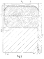
- Shoulder 27 is maintained at a given distance of other than zero from shoulder 14, so as to form an annular chamber 29 defined by shoulders 14 and 27 and by facing portions of faces 12 and 24.
- Valve body 17 has a hole 30 and nozzle for connecting annular chamber 29 to seat 9; and a hole 31 and nozzle for connecting seat 9 to seat 23 housing shutter 19.
- Injector 1 also comprises a seal 32 extending between face 12 and face 24 and adjacent to shoulder 14 to prevent fuel leaking from annular chamber 29 between face 11 of injector body 2 and face 24 of valve body 17.
- annular gap M which depends on the precision of the machines used to produce the component parts of injector 1, and which, at worst, is defined by a radial clearance of 0.02 mm.
- Seal 32 is made of PTFE, i.e. Teflon enriched with bronze particles, or of a material known commercially as TURCON ®.
- the life LF of injector 1 depends on the life of seal 32, and in particular on the permanent deformation to which seal 32 is subjected.
- the other quantities on which the life LF of injector 1 depends are dimensional quantities of valve body 17, of injector body 2, and of seal 32, the size of which depends on the size of annular chamber 29. More specifically, as will be clear from the equation, to extend the working life of the injector, a high, narrow chamber 29 is preferable to increase the h/d ratio.
- the size of annular chamber 29, however, depends on other design parameters, such as the width d of annular chamber 29, which corresponds to the width d of seal 32. Research by the Applicant has shown an h/d ratio of 1 to 2 gives good life LF values and enables adequate sizing of annular chamber 29, and that h/d ratios of 1.5 to 2 are in all cases preferable.
- seal 32 in which A substantially equals h x d, this gives : which gives the height h of seal 32, i.e. the only design parameter for determining life LF which is not affected by other characteristics of injector 1.
- life LF is predetermined; the maximum operating pressure P has a given value of 1500 bars, as does the maximum operating temperature T, which equals 180°C; the size of gap M is defined by the type of machining to form seat 5 of injector body 2 and valve body 17; and the width d of annular chamber 29 is determined according to the required hydraulic function of chamber 29.
- the size of gap M also depends on the mean diameter of gap M and therefore on the size of injector 1.
Landscapes
- Engineering & Computer Science (AREA)
- Chemical & Material Sciences (AREA)
- Combustion & Propulsion (AREA)
- Mechanical Engineering (AREA)
- General Engineering & Computer Science (AREA)
- Manufacturing & Machinery (AREA)
- Physics & Mathematics (AREA)
- Fluid Mechanics (AREA)
- Fuel-Injection Apparatus (AREA)
Abstract
Description


Claims (18)
- A method of producing fuel injectors for internal combustion engines, each injector (1) comprising an injector body (2) having a seat (5); a valve body (17) housed inside said seat (5) so as to form an annular chamber (29), for receiving high-pressure fuel, and a gap (M) communicating with said annular chamber (29); and a seal (32) for sealing said gap (M); the method being characterized by sizing said seal (32) as a function of the deformation to which said seal (32) is subjected during use of said injector (1), so as to achieve a predetermined working life (LF) of said injector (1).
- A method as claimed in Claim 1, characterized by sizing said seal (32) as a function of the permanent deformation to which said seal (32) is subjected during use of said injector (1).
- A method as claimed in Claim 1 or 2, characterized by sizing said seal (32) as a function of the size of said gap (M); the size of the seal (32) being inversely proportional to the size of said gap (M).
- A method as claimed in any one of the foregoing Claims, characterized in that said seal (32) is annular and has a height (h) and a width (d); said width being equal to the width of said annular chamber (29).
- A method as claimed in Claim 4, characterized by determining the height (h) of said seal as a function of a predetermined life (LF) of said injector (1).
- A method as claimed in Claim 5, characterized by determining the height (h) of said seal (32) as a function of the maximum operating pressure (P) and maximum operating temperature (T) of said injector (1).
- A method as claimed in any one of Claims 4 to 6, characterized by determining the height (h) of the seal (32) according to the equation:

- A method as claimed in one of the foregoing Claims, characterized in that said seal (32) is made of Teflon enriched with bronze particles.
- A method as claimed in one of Claims 1 to 7, characterized in that said seal is made of TURCON ®.
- A method as claimed in one of the foregoing Claims, characterized by predetermining the working life (LF) of the injector (1) equal to the working life of the internal combustion engine (E) on which said injector (1) is installed.
- A fuel injector for an internal combustion engine (E), the injector comprising an injector body (2) having a seat (5); a valve body (17) housed inside said seat (5) so as to form an annular chamber (29), for receiving high-pressure fuel, and a gap (M) communicating with said annular chamber (29); and a seal (32) for sealing said gap (M); the injector being characterized in that said seal (32) is sized as a function of the deformation to which said seal (32) is subjected during use of said injector (1), so as to obtain a predetermined working life (LF) of said injector (1).
- An injector as claimed in Claim 11, characterized in that said seal (32) is sized as a function of the size of said gap (M); the size of the seal (32) being inversely proportional to the size of said gap (M).
- An injector as claimed in Claim 11 or 12, characterized in that said seal (32) is annular and has a height (h) and a width (d) measured radially; said width (d) being equal to the width of said annular chamber (29).
- An injector as claimed in Claim 13, characterized by determining the height (h) of said seal (32) as a function of a predetermined life (LF) of said injector (1).
- An injector as claimed in Claim 14, characterized by determining the height (h) of said seal (32) as a function of the maximum operating pressure (P) and maximum operating temperature (T) of said injector (1).
- An injector as claimed in any one of Claims 13 to 15, characterized by determining the height (h) of the seal (32) according to the equation:

- An injector as claimed in any one of Claims 11 to 16, characterized in that said seal (32) is made of Teflon enriched with bronze particles.
- An injector as claimed in any one of Claims 11 to 16, characterized in that said seal is made of TURCON ®.
Applications Claiming Priority (2)
| Application Number | Priority Date | Filing Date | Title |
|---|---|---|---|
| IT2001TO000027A ITTO20010027A1 (en) | 2001-01-16 | 2001-01-16 | METHOD FOR REALIZING FUEL INJECTORS AND FUEL INJECTOR. |
| ITTO010027 | 2001-01-16 |
Publications (3)
| Publication Number | Publication Date |
|---|---|
| EP1223338A2 true EP1223338A2 (en) | 2002-07-17 |
| EP1223338A3 EP1223338A3 (en) | 2003-02-26 |
| EP1223338B1 EP1223338B1 (en) | 2006-11-22 |
Family
ID=11458386
Family Applications (1)
| Application Number | Title | Priority Date | Filing Date |
|---|---|---|---|
| EP01130860A Expired - Lifetime EP1223338B1 (en) | 2001-01-16 | 2001-12-27 | Method of producing a fuel injector |
Country Status (6)
| Country | Link |
|---|---|
| US (1) | US6896194B2 (en) |
| EP (1) | EP1223338B1 (en) |
| AT (1) | ATE346232T1 (en) |
| DE (1) | DE60124663T2 (en) |
| ES (1) | ES2272404T3 (en) |
| IT (1) | ITTO20010027A1 (en) |
Cited By (2)
| Publication number | Priority date | Publication date | Assignee | Title |
|---|---|---|---|---|
| EP1612399A1 (en) * | 2004-06-30 | 2006-01-04 | C.R.F. Società Consortile per Azioni | A fuel injector for an internal combustion engine |
| WO2009042199A1 (en) * | 2007-09-27 | 2009-04-02 | Caterpillar Inc. | High-pressure pump or injector plug or guide with decoupled sealing land |
Families Citing this family (1)
| Publication number | Priority date | Publication date | Assignee | Title |
|---|---|---|---|---|
| US20050087624A1 (en) * | 2002-05-10 | 2005-04-28 | Siemens Aktiengesellschaft | Injector for fuel injection |
Citations (4)
| Publication number | Priority date | Publication date | Assignee | Title |
|---|---|---|---|---|
| DE1940698A1 (en) * | 1968-08-21 | 1970-11-26 | Shamban & Co W S | Sealing arrangement |
| US5004015A (en) * | 1984-03-01 | 1991-04-02 | Mannesmann Rexroth Gmbh | Directional control device |
| EP0483770A1 (en) * | 1990-10-31 | 1992-05-06 | ELASIS SISTEMA RICERCA FIAT NEL MEZZOGIORNO Società Consortile per Azioni | Perfected high pressure sealing system for the control valve of an electromagnetic internal combustion engine fuel injector |
| WO1999037909A1 (en) * | 1998-01-22 | 1999-07-29 | Robert Bosch Gmbh | Fuel injection valve for internal combustion engines |
Family Cites Families (6)
| Publication number | Priority date | Publication date | Assignee | Title |
|---|---|---|---|---|
| US5145008A (en) * | 1985-04-05 | 1992-09-08 | Crown Cork & Seal Company, Inc. | Filling valve for counterpressure filling of cans |
| IT212431Z2 (en) * | 1987-08-25 | 1989-07-04 | Weber Srl | THE ELECTROMAGNETIC CONTROL FOR FUEL INJECTION VALVE DIESEL CYCLE ENGINES |
| IT1240173B (en) * | 1990-04-06 | 1993-11-27 | Weber Srl | ELECTROMAGNETICALLY OPERATED FUEL INJECTION DEVICE FOR AN INTERNAL COMBUSTION ENGINE |
| CH689282A5 (en) * | 1994-03-29 | 1999-01-29 | Christian Dipl-Ing Eth Mathis | Injection valve for a particular intended as a diesel engine internal combustion engine. |
| US5971285A (en) * | 1996-03-26 | 1999-10-26 | Masco Corporation Of Indiana | Thermostatically controlled mixing valve |
| ITTO20001230A1 (en) * | 2000-12-29 | 2002-06-29 | Fiat Ricerche | FUEL INJECTOR FOR AN INTERNAL COMBUSTION ENGINE. |
-
2001
- 2001-01-16 IT IT2001TO000027A patent/ITTO20010027A1/en unknown
- 2001-12-27 EP EP01130860A patent/EP1223338B1/en not_active Expired - Lifetime
- 2001-12-27 AT AT01130860T patent/ATE346232T1/en not_active IP Right Cessation
- 2001-12-27 ES ES01130860T patent/ES2272404T3/en not_active Expired - Lifetime
- 2001-12-27 DE DE60124663T patent/DE60124663T2/en not_active Expired - Lifetime
- 2001-12-28 US US10/034,634 patent/US6896194B2/en not_active Expired - Fee Related
Patent Citations (4)
| Publication number | Priority date | Publication date | Assignee | Title |
|---|---|---|---|---|
| DE1940698A1 (en) * | 1968-08-21 | 1970-11-26 | Shamban & Co W S | Sealing arrangement |
| US5004015A (en) * | 1984-03-01 | 1991-04-02 | Mannesmann Rexroth Gmbh | Directional control device |
| EP0483770A1 (en) * | 1990-10-31 | 1992-05-06 | ELASIS SISTEMA RICERCA FIAT NEL MEZZOGIORNO Società Consortile per Azioni | Perfected high pressure sealing system for the control valve of an electromagnetic internal combustion engine fuel injector |
| WO1999037909A1 (en) * | 1998-01-22 | 1999-07-29 | Robert Bosch Gmbh | Fuel injection valve for internal combustion engines |
Cited By (4)
| Publication number | Priority date | Publication date | Assignee | Title |
|---|---|---|---|---|
| EP1612399A1 (en) * | 2004-06-30 | 2006-01-04 | C.R.F. Società Consortile per Azioni | A fuel injector for an internal combustion engine |
| US7748644B2 (en) | 2004-06-30 | 2010-07-06 | C.R.F. Societa Consortile Per Azioni | Fuel injector for an internal-combustion engine |
| WO2009042199A1 (en) * | 2007-09-27 | 2009-04-02 | Caterpillar Inc. | High-pressure pump or injector plug or guide with decoupled sealing land |
| US7628140B2 (en) | 2007-09-27 | 2009-12-08 | Caterpillar Inc. | High-pressure pump or injector plug or guide with decoupled sealing land |
Also Published As
| Publication number | Publication date |
|---|---|
| ES2272404T3 (en) | 2007-05-01 |
| ITTO20010027A0 (en) | 2001-01-16 |
| EP1223338A3 (en) | 2003-02-26 |
| EP1223338B1 (en) | 2006-11-22 |
| ITTO20010027A1 (en) | 2002-07-16 |
| DE60124663T2 (en) | 2007-09-13 |
| DE60124663D1 (en) | 2007-01-04 |
| US20020130203A1 (en) | 2002-09-19 |
| ATE346232T1 (en) | 2006-12-15 |
| US6896194B2 (en) | 2005-05-24 |
Similar Documents
| Publication | Publication Date | Title |
|---|---|---|
| US8291927B2 (en) | Remanufactured machine component and valve body remanufacturing process | |
| US20120251365A1 (en) | High pressure fuel pump | |
| US6941915B1 (en) | Hydraulic lash adjuster and improved method of assembly thereof | |
| EP1223338A2 (en) | Fuel injector and method of producing a fuel injector | |
| KR20160119109A (en) | Plunger fuel pump for an internal combustion engine | |
| US6364641B2 (en) | Fuel injection pump | |
| GB2224774A (en) | Die cast i.c. engine fuel injector and pressure regulator support manifold | |
| US4591100A (en) | Injection nozzle | |
| US7011256B2 (en) | Device for supplying high pressure fuel to an internal combustion engine | |
| WO2003106842A1 (en) | High pressure reciprocating pump | |
| CN102265022A (en) | Fuel injection system | |
| EP1288486A3 (en) | Leakage channel in a high-pressure fuel system | |
| US8046917B2 (en) | Method of refurbishing a diesel injector valve seat | |
| US7458155B2 (en) | Method of producing a fuel injector | |
| US20100183449A1 (en) | High-pressure pump for supplying fuel to an internal-combustion engine | |
| CN107209522A (en) | Pressure-reducing valve | |
| US7650906B2 (en) | Valve apparatus having O-ring | |
| CN110740798B (en) | Fuel injection system filter | |
| KR100328173B1 (en) | Swivel flow generator of the injection valve manufactured by the manufacturing method of the slide part and the manufacturing method | |
| US11352992B2 (en) | Fuel injector | |
| CN111550343A (en) | Seal structure for fuel injector | |
| EP3009660B1 (en) | Valve assembly with a guiding element and fluid injector | |
| US11859585B2 (en) | Electrical connector | |
| WO2021187015A1 (en) | Gasoline direct-injection rail | |
| WO2019129410A1 (en) | A fuel injector having a fuel channel with optimized durability |
Legal Events
| Date | Code | Title | Description |
|---|---|---|---|
| PUAI | Public reference made under article 153(3) epc to a published international application that has entered the european phase |
Free format text: ORIGINAL CODE: 0009012 |
|
| AK | Designated contracting states |
Kind code of ref document: A2 Designated state(s): AT BE CH CY DE DK ES FI FR GB GR IE IT LI LU MC NL PT SE TR |
|
| AX | Request for extension of the european patent |
Free format text: AL;LT;LV;MK;RO;SI |
|
| PUAL | Search report despatched |
Free format text: ORIGINAL CODE: 0009013 |
|
| AK | Designated contracting states |
Designated state(s): AT BE CH CY DE DK ES FI FR GB GR IE IT LI LU MC NL PT SE TR Kind code of ref document: A3 Designated state(s): AT BE CH CY DE DK ES FI FR GB GR IE IT LI LU MC NL PT SE TR |
|
| AX | Request for extension of the european patent |
Extension state: AL LT LV MK RO SI |
|
| 17P | Request for examination filed |
Effective date: 20030822 |
|
| AKX | Designation fees paid |
Designated state(s): AT BE CH CY DE DK ES FI FR GB GR IE IT LI LU MC NL PT SE TR |
|
| 17Q | First examination report despatched |
Effective date: 20050616 |
|
| GRAP | Despatch of communication of intention to grant a patent |
Free format text: ORIGINAL CODE: EPIDOSNIGR1 |
|
| RTI1 | Title (correction) |
Free format text: METHOD OF PRODUCING A FUEL INJECTOR |
|
| GRAS | Grant fee paid |
Free format text: ORIGINAL CODE: EPIDOSNIGR3 |
|
| GRAA | (expected) grant |
Free format text: ORIGINAL CODE: 0009210 |
|
| AK | Designated contracting states |
Kind code of ref document: B1 Designated state(s): AT BE CH CY DE DK ES FI FR GB GR IE IT LI LU MC NL PT SE TR |
|
| PG25 | Lapsed in a contracting state [announced via postgrant information from national office to epo] |
Ref country code: NL Free format text: LAPSE BECAUSE OF FAILURE TO SUBMIT A TRANSLATION OF THE DESCRIPTION OR TO PAY THE FEE WITHIN THE PRESCRIBED TIME-LIMIT Effective date: 20061122 Ref country code: BE Free format text: LAPSE BECAUSE OF FAILURE TO SUBMIT A TRANSLATION OF THE DESCRIPTION OR TO PAY THE FEE WITHIN THE PRESCRIBED TIME-LIMIT Effective date: 20061122 Ref country code: LI Free format text: LAPSE BECAUSE OF FAILURE TO SUBMIT A TRANSLATION OF THE DESCRIPTION OR TO PAY THE FEE WITHIN THE PRESCRIBED TIME-LIMIT Effective date: 20061122 Ref country code: FI Free format text: LAPSE BECAUSE OF FAILURE TO SUBMIT A TRANSLATION OF THE DESCRIPTION OR TO PAY THE FEE WITHIN THE PRESCRIBED TIME-LIMIT Effective date: 20061122 Ref country code: AT Free format text: LAPSE BECAUSE OF FAILURE TO SUBMIT A TRANSLATION OF THE DESCRIPTION OR TO PAY THE FEE WITHIN THE PRESCRIBED TIME-LIMIT Effective date: 20061122 Ref country code: CH Free format text: LAPSE BECAUSE OF FAILURE TO SUBMIT A TRANSLATION OF THE DESCRIPTION OR TO PAY THE FEE WITHIN THE PRESCRIBED TIME-LIMIT Effective date: 20061122 |
|
| REG | Reference to a national code |
Ref country code: GB Ref legal event code: FG4D |
|
| REG | Reference to a national code |
Ref country code: CH Ref legal event code: EP |
|
| PG25 | Lapsed in a contracting state [announced via postgrant information from national office to epo] |
Ref country code: IE Free format text: LAPSE BECAUSE OF NON-PAYMENT OF DUE FEES Effective date: 20061228 |
|
| REG | Reference to a national code |
Ref country code: IE Ref legal event code: FG4D |
|
| PG25 | Lapsed in a contracting state [announced via postgrant information from national office to epo] |
Ref country code: MC Free format text: LAPSE BECAUSE OF NON-PAYMENT OF DUE FEES Effective date: 20061231 |
|
| REF | Corresponds to: |
Ref document number: 60124663 Country of ref document: DE Date of ref document: 20070104 Kind code of ref document: P |
|
| REG | Reference to a national code |
Ref country code: SE Ref legal event code: TRGR |
|
| PG25 | Lapsed in a contracting state [announced via postgrant information from national office to epo] |
Ref country code: DK Free format text: LAPSE BECAUSE OF FAILURE TO SUBMIT A TRANSLATION OF THE DESCRIPTION OR TO PAY THE FEE WITHIN THE PRESCRIBED TIME-LIMIT Effective date: 20070222 |
|
| ET | Fr: translation filed | ||
| PG25 | Lapsed in a contracting state [announced via postgrant information from national office to epo] |
Ref country code: PT Free format text: LAPSE BECAUSE OF FAILURE TO SUBMIT A TRANSLATION OF THE DESCRIPTION OR TO PAY THE FEE WITHIN THE PRESCRIBED TIME-LIMIT Effective date: 20070423 |
|
| NLV1 | Nl: lapsed or annulled due to failure to fulfill the requirements of art. 29p and 29m of the patents act | ||
| REG | Reference to a national code |
Ref country code: ES Ref legal event code: FG2A Ref document number: 2272404 Country of ref document: ES Kind code of ref document: T3 |
|
| REG | Reference to a national code |
Ref country code: CH Ref legal event code: PL |
|
| PLBE | No opposition filed within time limit |
Free format text: ORIGINAL CODE: 0009261 |
|
| STAA | Information on the status of an ep patent application or granted ep patent |
Free format text: STATUS: NO OPPOSITION FILED WITHIN TIME LIMIT |
|
| 26N | No opposition filed |
Effective date: 20070823 |
|
| PG25 | Lapsed in a contracting state [announced via postgrant information from national office to epo] |
Ref country code: GR Free format text: LAPSE BECAUSE OF FAILURE TO SUBMIT A TRANSLATION OF THE DESCRIPTION OR TO PAY THE FEE WITHIN THE PRESCRIBED TIME-LIMIT Effective date: 20070223 |
|
| PG25 | Lapsed in a contracting state [announced via postgrant information from national office to epo] |
Ref country code: LU Free format text: LAPSE BECAUSE OF NON-PAYMENT OF DUE FEES Effective date: 20061227 Ref country code: TR Free format text: LAPSE BECAUSE OF FAILURE TO SUBMIT A TRANSLATION OF THE DESCRIPTION OR TO PAY THE FEE WITHIN THE PRESCRIBED TIME-LIMIT Effective date: 20061122 |
|
| PG25 | Lapsed in a contracting state [announced via postgrant information from national office to epo] |
Ref country code: CY Free format text: LAPSE BECAUSE OF FAILURE TO SUBMIT A TRANSLATION OF THE DESCRIPTION OR TO PAY THE FEE WITHIN THE PRESCRIBED TIME-LIMIT Effective date: 20061122 |
|
| PGFP | Annual fee paid to national office [announced via postgrant information from national office to epo] |
Ref country code: GB Payment date: 20101222 Year of fee payment: 10 |
|
| PGFP | Annual fee paid to national office [announced via postgrant information from national office to epo] |
Ref country code: SE Payment date: 20111213 Year of fee payment: 11 |
|
| PGFP | Annual fee paid to national office [announced via postgrant information from national office to epo] |
Ref country code: ES Payment date: 20120116 Year of fee payment: 11 |
|
| PG25 | Lapsed in a contracting state [announced via postgrant information from national office to epo] |
Ref country code: SE Free format text: LAPSE BECAUSE OF NON-PAYMENT OF DUE FEES Effective date: 20121228 |
|
| GBPC | Gb: european patent ceased through non-payment of renewal fee |
Effective date: 20121227 |
|
| PG25 | Lapsed in a contracting state [announced via postgrant information from national office to epo] |
Ref country code: GB Free format text: LAPSE BECAUSE OF NON-PAYMENT OF DUE FEES Effective date: 20121227 |
|
| REG | Reference to a national code |
Ref country code: ES Ref legal event code: FD2A Effective date: 20140307 |
|
| PG25 | Lapsed in a contracting state [announced via postgrant information from national office to epo] |
Ref country code: ES Free format text: LAPSE BECAUSE OF NON-PAYMENT OF DUE FEES Effective date: 20121228 |
|
| REG | Reference to a national code |
Ref country code: FR Ref legal event code: PLFP Year of fee payment: 15 |
|
| PGFP | Annual fee paid to national office [announced via postgrant information from national office to epo] |
Ref country code: IT Payment date: 20151120 Year of fee payment: 15 |
|
| PGFP | Annual fee paid to national office [announced via postgrant information from national office to epo] |
Ref country code: FR Payment date: 20151110 Year of fee payment: 15 |
|
| PGFP | Annual fee paid to national office [announced via postgrant information from national office to epo] |
Ref country code: DE Payment date: 20151222 Year of fee payment: 15 |
|
| REG | Reference to a national code |
Ref country code: DE Ref legal event code: R119 Ref document number: 60124663 Country of ref document: DE |
|
| REG | Reference to a national code |
Ref country code: FR Ref legal event code: ST Effective date: 20170831 |
|
| PG25 | Lapsed in a contracting state [announced via postgrant information from national office to epo] |
Ref country code: FR Free format text: LAPSE BECAUSE OF NON-PAYMENT OF DUE FEES Effective date: 20170102 Ref country code: IT Free format text: LAPSE BECAUSE OF NON-PAYMENT OF DUE FEES Effective date: 20161227 |
|
| PG25 | Lapsed in a contracting state [announced via postgrant information from national office to epo] |
Ref country code: DE Free format text: LAPSE BECAUSE OF NON-PAYMENT OF DUE FEES Effective date: 20170701 |