EP1223309A1 - Système de rétention des aubes de type combine ou casade - Google Patents
Système de rétention des aubes de type combine ou casade Download PDFInfo
- Publication number
- EP1223309A1 EP1223309A1 EP02290048A EP02290048A EP1223309A1 EP 1223309 A1 EP1223309 A1 EP 1223309A1 EP 02290048 A EP02290048 A EP 02290048A EP 02290048 A EP02290048 A EP 02290048A EP 1223309 A1 EP1223309 A1 EP 1223309A1
- Authority
- EP
- European Patent Office
- Prior art keywords
- disc
- flange
- radial
- blade
- fan blades
- Prior art date
- Legal status (The legal status is an assumption and is not a legal conclusion. Google has not performed a legal analysis and makes no representation as to the accuracy of the status listed.)
- Granted
Links
- 230000014759 maintenance of location Effects 0.000 title description 8
- 238000011144 upstream manufacturing Methods 0.000 claims abstract description 16
- 238000006073 displacement reaction Methods 0.000 description 3
- 230000000717 retained effect Effects 0.000 description 2
- 238000003754 machining Methods 0.000 description 1
Images


Classifications
-
- F—MECHANICAL ENGINEERING; LIGHTING; HEATING; WEAPONS; BLASTING
- F01—MACHINES OR ENGINES IN GENERAL; ENGINE PLANTS IN GENERAL; STEAM ENGINES
- F01D—NON-POSITIVE DISPLACEMENT MACHINES OR ENGINES, e.g. STEAM TURBINES
- F01D5/00—Blades; Blade-carrying members; Heating, heat-insulating, cooling or antivibration means on the blades or the members
- F01D5/30—Fixing blades to rotors; Blade roots ; Blade spacers
- F01D5/32—Locking, e.g. by final locking blades or keys
- F01D5/323—Locking of axial insertion type blades by means of a key or the like parallel to the axis of the rotor
-
- F—MECHANICAL ENGINEERING; LIGHTING; HEATING; WEAPONS; BLASTING
- F01—MACHINES OR ENGINES IN GENERAL; ENGINE PLANTS IN GENERAL; STEAM ENGINES
- F01D—NON-POSITIVE DISPLACEMENT MACHINES OR ENGINES, e.g. STEAM TURBINES
- F01D5/00—Blades; Blade-carrying members; Heating, heat-insulating, cooling or antivibration means on the blades or the members
- F01D5/30—Fixing blades to rotors; Blade roots ; Blade spacers
- F01D5/3007—Fixing blades to rotors; Blade roots ; Blade spacers of axial insertion type
- F01D5/3015—Fixing blades to rotors; Blade roots ; Blade spacers of axial insertion type with side plates
Definitions
- the present invention relates to a semi-collective blade retention system turbojet engines.
- turbojet fan rotor comprising a plurality of removable fan blades fixed on a rim of a disc, said fan blades each comprising a blade root which is mounted in a substantially axial groove of corresponding shape, formed in the disc rim, each of the fan blades being held in the groove by a wedge placed below each blade root, and means for retaining axially the wedges and the feet of blades in the grooves, said means comprising in particular a flange bearing against the upstream face of the disc and fixed to said disc by fixing means.
- the upstream side designates the side facing the front of the engine and the downstream side, that facing back.
- a radially inner part designates an area close to the axis of rotation of the disc, and a portion radially outside, the one that is far from it.
- the document FR A 2 681 374 describes a fixing of fan blades of turbojet engine using scalloped flanges arranged upstream and downstream at the periphery of the disc and provided with holes, intended for the fixing of two rings provided respectively on a front cover and a compressor drum, which cooperate with the ends of the blade roots to immobilize them axially and radially.
- the fan blades have two spoilers on the downstream part of their feet which engage respectively on the internal and external radial faces of a first ring, and also present on the upstream part of their feet two spoilers which engage respectively on the inner and outer radial faces of a second ring.
- This locking device complicates the machining of the fan blades which have two spoilers at their two ends, and makes it difficult and long to replace a blade damaged, because it is necessary to unscrew the plurality of fixing pins of a ring, these pins accommodating in the orifices of a scalloped flange and being of a difficult access.
- the object of the invention is to propose a fan rotor as described in introduction in which the blades are retained in cascade in the event of displacement axial.
- the wedges comprise at one of their ends a protrusion interposed between the blade roots and the flange, by the causes the disc to have a plurality of radial protrusions on its upstream face alternating with the grooves, by the fact that the flange has on its downstream face a plurality of radial teeth capable of bearing against the protuberances radial of the disc in the event of axial movement of a blade, and by the fact that the means for fixing the flange to the disc are arranged in the radially inner part flaccid.
- the fan blades are stopped in cascade from the as follows: the fan blade first rests on the block, then at least one radial flange tooth cooperates in part with a protuberance of the disc for immobilize the fan blade.
- the flange fixing means contribute to the definitive end of the fan dawn.
- the radial protrusions of the disc extend towards outside, and the radial teeth of the flange extend inward.
- said radial protrusions of the disc extend towards the inside and said radial teeth of the flange towards the outside.
- an axial clearance is provided between the radial protrusions of the disc and radial teeth of the flange.
- This game dissipates part of the energy when the fan dawn, retained by the wedge, moves axially.
- the means for fixing the flange to the disc have a plurality of pins parallel to the axis of rotation of the disc.
- pins are in sufficient number to retain the flange on the disc in case axial displacement of a fan blade.
- they include a screw-nut assembly collecting the axial forces and the shear forces.
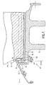
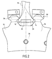
- FIGS. 1 and 2 show a fan rotor disk 10 comprising a rim 12 which has at its periphery a plurality of substantially axial grooves 14 and regularly spaced around the axis of rotation of the disc 10.
- each groove 14 is mounted by sliding axially a foot 16 of a fan blade 18. Between the blade root 16 and the bottom of the groove 14 is engaged a wedge 20 which keeps the blade root 16 in abutment against the walls of the groove 14 corresponding.
- Each wedge 20 has a protuberance 22 at one of its ends.
- this protuberance 22 is located at the upstream end of the wedge 20, between the upstream face of the blade root 16 and a flange 24 bearing against the upstream face of the disc 10.
- the flange 24 is formed by an internal wall of a ferrule which delimits internally the air flow channel through the blower.
- the disc 10 has on its upstream face and alternating with the grooves 14, a plurality of radial protrusions 26 directed outwards.
- the flange 24 has on its downstream face a plurality of radial teeth 28 directed inwards, likely to come to bear against the radial protrusions 26 of the disc 10.
- Figure 3 shows that to mount the flange 24 on the disc 10 (position unlocked), the radial teeth 28 of the flange 24 are passed through the notches 30 interposed between the radial protrusions 26 of the disc 10 and located above the bottom of grooves 14.
- Figure 4 shows the flange 24 in the locked position.
- the width of the teeth radial 28 of the flange 24 may be greater than that of the radial protrusions 26 of the disc 10, so that a fraction of each of the radial teeth 28 allows to wedge axially a part of each fan blade 18.
- the flange 24 is held in position by a simple screw / nut assembly.
- the means for fixing the flange 24 include locking means constituted by pins comprising screws 44 and nuts 46.
- Figure 5 shows a flange 42 bolted with said screws 44 and said nuts 46 crimped in the disc 10.
- the disc 10 which is unchanged in its radially outer part (protuberances radials 26) is thus of simpler shape in its radially inner part. It the same applies to the flange 24.
- This bolted flange system 42 serves both to maintain the rotation of the flange 24 relative to the disc 10, and to its axial retention, which requires a number therefore pins.
- Figure 6 shows that the disc 10 has partly radially inside a plurality of holes intended to hold the flange 24 on the disc 10. The attachment of the flange 24 to the disc 10 is done, for example, using a plurality of screws 44 and nuts 46, so as to keep the flange 24 tight on the disc 10 even if an attempt is made to lose a blade.
- the screw-nut assembly 44, 46 locks the flange 24 on the disc 10.
Landscapes
- Engineering & Computer Science (AREA)
- Mechanical Engineering (AREA)
- General Engineering & Computer Science (AREA)
- Structures Of Non-Positive Displacement Pumps (AREA)
Abstract
Description
- la figure 1 est une coupe du système de rétention axiale des aubes de soufflante de type combiné ou cascade selon l'invention, la flèche F, orientée de l'amont vers l'aval, représentant en outre le sens d'écoulement de l'air ;
- la figure 2 est une coupe selon la ligne II-II de la figure 1, le flasque étant enlevé ;
- la figure 3 est une perspective isométrique partielle, de l'aval vers l'amont, de la partie extérieure du disque comportant une seule cale par souci de clarté, qui montre le flasque en position déverrouillée ;
- la figure 4 est identique à la figure 3 avec le flasque en position verrouillée ;
- la figure 5 est une coupe du système de rétention axiale des aubes de soufflante de type combiné ou cascade selon l'invention ; et
- la figure 6 est une vue de l'amont vers l'aval, du disque sans le flasque.
Claims (4)
- Rotor de soufflante de turboréacteur, comportant une pluralité d'aubes de soufflante amovibles (18) fixées sur une jante (12) d'un disque (10), lesdites aubes de soufflante (18) comportant chacune un pied d'aube (16) qui est monté dans une rainure (14), sensiblement axiale et de forme correspondante, ménagée dans la jante (12) du disque (10), chacune des aubes de soufflante (18) étant maintenue dans la rainure (14) par une cale (20) placée en-dessous de chaque pied d'aube (16), et des moyens pour retenir axialement les cales (20) et les pieds d'aubes (16) dans les rainures (14), lesdits moyens comportant notamment un flasque (24) en appui contre la face amont du disque (10) et fixé audit disque (10) par des moyens de fixation,
caractérisé par le fait que les cales (20) comportent à l'une de leurs extrémités une excroissance (22) interposée entre les pieds d'aubes (16) et le flasque (24), par le fait que le disque (10) comporte sur sa face amont une pluralité de protubérances radiales (26) alternant avec les rainures (14), par le fait que le flasque (24) comporte sur sa face aval une pluralité de dents radiales (28) susceptibles de venir en appui contre les protubérances radiales (26) du disque (10) en cas de déplacement axial d'une aube (16), et par le fait que les moyens de fixation du flasque (24) sur le disque (10) sont disposé dans la partie radialement intérieure du flasque. - Rotor de soufflante selon la revendication 1, caractérisé par le fait que les protubérances radiales (26) du disque (10) s'étendent vers l'extérieur ou l'intérieur, et les dents radiales (28) du flasque (24) s'étendent vers l'intérieur ou l'extérieur.
- Rotor de soufflante selon la revendication 1 ou 2, caractérisé par le fait qu'un jeu axial (48) est ménagé entre les protubérances radiales (26) du disque (10) et les dents radiales (28) du flasque (24).
- Rotor de soufflante selon l'une quelconque des revendications 1 à 3, caractérisé par le fait que les moyens de fixation du flasque (24) sur le disque (10) comportent une pluralité de broches (42, 44, 46) parallèles à l'axe de rotation du disque (10).
Applications Claiming Priority (2)
| Application Number | Priority Date | Filing Date | Title |
|---|---|---|---|
| FR0100294 | 2001-01-11 | ||
| FR0100294A FR2819289B1 (fr) | 2001-01-11 | 2001-01-11 | Systeme de retention des aubes de type combine ou cascade |
Publications (2)
| Publication Number | Publication Date |
|---|---|
| EP1223309A1 true EP1223309A1 (fr) | 2002-07-17 |
| EP1223309B1 EP1223309B1 (fr) | 2005-06-08 |
Family
ID=8858676
Family Applications (1)
| Application Number | Title | Priority Date | Filing Date |
|---|---|---|---|
| EP02290048A Expired - Lifetime EP1223309B1 (fr) | 2001-01-11 | 2002-01-10 | Système de rétention des aubes de type combine ou cascade |
Country Status (9)
| Country | Link |
|---|---|
| US (1) | US20020090300A1 (fr) |
| EP (1) | EP1223309B1 (fr) |
| JP (1) | JP4031247B2 (fr) |
| CA (1) | CA2364128A1 (fr) |
| DE (1) | DE60204486T2 (fr) |
| ES (1) | ES2240665T3 (fr) |
| FR (1) | FR2819289B1 (fr) |
| RU (1) | RU2221169C2 (fr) |
| UA (1) | UA72255C2 (fr) |
Cited By (4)
| Publication number | Priority date | Publication date | Assignee | Title |
|---|---|---|---|---|
| EP1849962A1 (fr) * | 2006-04-27 | 2007-10-31 | Snecma | Système de rétention des aubes dans un rotor |
| FR2930595A1 (fr) * | 2008-04-24 | 2009-10-30 | Snecma Sa | Rotor de soufflante d'une turbomachine ou d'un moteur d'essai |
| EP1995467A4 (fr) * | 2006-03-13 | 2013-01-02 | Ihi Corp | Structure support pour pale de ventilateur |
| FR2996584A1 (fr) * | 2012-10-10 | 2014-04-11 | Snecma | Cale pour pied de pale ajouree |
Families Citing this family (7)
| Publication number | Priority date | Publication date | Assignee | Title |
|---|---|---|---|---|
| JP4807113B2 (ja) * | 2006-03-14 | 2011-11-02 | 株式会社Ihi | ファンのダブテール構造 |
| FR2913735B1 (fr) * | 2007-03-16 | 2013-04-19 | Snecma | Disque de rotor d'une turbomachine |
| FR2929660B1 (fr) * | 2008-04-07 | 2012-11-16 | Snecma | Dispositif anti-usure pour rotor de turbomachine, bouchon formant dispositif anti-usure et rotor de compresseur de moteur a turbine a gaz comportant un bouchon anti-usure |
| FR2931871B1 (fr) * | 2008-05-29 | 2011-08-19 | Snecma | Rotor de soufflante pour une turbomachine. |
| FR2971822B1 (fr) * | 2011-02-21 | 2015-04-24 | Snecma | Rotor de soufflante, en particulier pour une turbomachine |
| CN106224360A (zh) * | 2016-07-25 | 2016-12-14 | 珠海格力节能环保制冷技术研究中心有限公司 | 风扇与电机轴安装结构 |
| CN113083537B (zh) * | 2021-05-08 | 2024-08-30 | 广州极飞科技股份有限公司 | 离心喷盘、雾化装置和无人设备 |
Citations (4)
| Publication number | Priority date | Publication date | Assignee | Title |
|---|---|---|---|---|
| US3096074A (en) * | 1960-12-06 | 1963-07-02 | Rolls Royce | Bladed rotors of machines such as gas turbines |
| FR2561307A1 (fr) * | 1984-03-14 | 1985-09-20 | Snecma | Dispositif de verrouillage d'aubes de soufflantes |
| GB2244100A (en) * | 1990-05-16 | 1991-11-20 | Rolls Royce Plc | Retaining gas turbine rotor blades |
| US5173024A (en) * | 1990-06-27 | 1992-12-22 | Societe Nationale D'etude Et De Construction De Moteurs D'aviation | Fixing arrangement for mounting an annular member on a disk of a turboshaft engine |
Family Cites Families (3)
| Publication number | Priority date | Publication date | Assignee | Title |
|---|---|---|---|---|
| SE7502749L (sv) * | 1975-03-12 | 1976-09-13 | Stal Laval Turbin Ab | Lophjul for axialturbin |
| US4595340A (en) * | 1984-07-30 | 1986-06-17 | General Electric Company | Gas turbine bladed disk assembly |
| FR2681374B1 (fr) | 1991-09-18 | 1993-11-19 | Snecma | Fixation d'aube de souflante de turboreacteur. |
-
2001
- 2001-01-11 FR FR0100294A patent/FR2819289B1/fr not_active Expired - Fee Related
- 2001-12-10 CA CA002364128A patent/CA2364128A1/fr not_active Abandoned
-
2002
- 2002-01-10 JP JP2002003012A patent/JP4031247B2/ja not_active Expired - Lifetime
- 2002-01-10 RU RU2002101357/06A patent/RU2221169C2/ru active
- 2002-01-10 ES ES02290048T patent/ES2240665T3/es not_active Expired - Lifetime
- 2002-01-10 EP EP02290048A patent/EP1223309B1/fr not_active Expired - Lifetime
- 2002-01-10 US US10/041,580 patent/US20020090300A1/en not_active Abandoned
- 2002-01-10 DE DE60204486T patent/DE60204486T2/de not_active Expired - Lifetime
- 2002-01-10 UA UA2002010282A patent/UA72255C2/uk unknown
Patent Citations (4)
| Publication number | Priority date | Publication date | Assignee | Title |
|---|---|---|---|---|
| US3096074A (en) * | 1960-12-06 | 1963-07-02 | Rolls Royce | Bladed rotors of machines such as gas turbines |
| FR2561307A1 (fr) * | 1984-03-14 | 1985-09-20 | Snecma | Dispositif de verrouillage d'aubes de soufflantes |
| GB2244100A (en) * | 1990-05-16 | 1991-11-20 | Rolls Royce Plc | Retaining gas turbine rotor blades |
| US5173024A (en) * | 1990-06-27 | 1992-12-22 | Societe Nationale D'etude Et De Construction De Moteurs D'aviation | Fixing arrangement for mounting an annular member on a disk of a turboshaft engine |
Cited By (10)
| Publication number | Priority date | Publication date | Assignee | Title |
|---|---|---|---|---|
| EP1995467A4 (fr) * | 2006-03-13 | 2013-01-02 | Ihi Corp | Structure support pour pale de ventilateur |
| EP1849962A1 (fr) * | 2006-04-27 | 2007-10-31 | Snecma | Système de rétention des aubes dans un rotor |
| FR2900437A1 (fr) * | 2006-04-27 | 2007-11-02 | Snecma Sa | Systeme de retention des aubes dans un rotor |
| US7824157B2 (en) | 2006-04-27 | 2010-11-02 | Snecma | System for retaining blades in a rotor |
| RU2423624C2 (ru) * | 2006-04-27 | 2011-07-10 | Снекма | Ротор компрессора авиационного турбореактивного двигателя, компрессор и турбореактивный двигатель |
| FR2930595A1 (fr) * | 2008-04-24 | 2009-10-30 | Snecma Sa | Rotor de soufflante d'une turbomachine ou d'un moteur d'essai |
| US8092183B2 (en) | 2008-04-24 | 2012-01-10 | Snecma | Fan rotor for a turbomachine or a test engine |
| RU2487250C2 (ru) * | 2008-04-24 | 2013-07-10 | Снекма | Ротор вентилятора газотурбинного двигателя или опытного двигателя |
| FR2996584A1 (fr) * | 2012-10-10 | 2014-04-11 | Snecma | Cale pour pied de pale ajouree |
| US9453414B2 (en) | 2012-10-10 | 2016-09-27 | Snecma | Cleat for open-work blade foot |
Also Published As
| Publication number | Publication date |
|---|---|
| UA72255C2 (uk) | 2005-02-15 |
| JP4031247B2 (ja) | 2008-01-09 |
| US20020090300A1 (en) | 2002-07-11 |
| FR2819289A1 (fr) | 2002-07-12 |
| RU2221169C2 (ru) | 2004-01-10 |
| EP1223309B1 (fr) | 2005-06-08 |
| FR2819289B1 (fr) | 2003-07-11 |
| DE60204486D1 (de) | 2005-07-14 |
| DE60204486T2 (de) | 2006-05-11 |
| CA2364128A1 (fr) | 2002-07-11 |
| ES2240665T3 (es) | 2005-10-16 |
| JP2002242888A (ja) | 2002-08-28 |
Similar Documents
| Publication | Publication Date | Title |
|---|---|---|
| CA2644335C (fr) | Etage de turbine ou de compresseur, en particulier de turbomachine | |
| EP1223309B1 (fr) | Système de rétention des aubes de type combine ou cascade | |
| EP2678531B1 (fr) | Rotor de soufflante et turboréacteur associé | |
| EP3074638A1 (fr) | Soufflante pour une turbomachine | |
| FR2939834A1 (fr) | Roue de turbine avec systeme de retention axiale des aubes | |
| FR3014151A1 (fr) | Soufflante, en particulier pour une turbomachine | |
| EP2060751B1 (fr) | Etage de turbine ou de compresseur d'un turboréacteur | |
| CA2557765C (fr) | Dispositif d'immobilisation d'un anneau de retention axiale d'une aube, disque de rotor et anneau de retention associes, et rotor et moteur d'aeronef les comportant | |
| CA2554092A1 (fr) | Verrouillage des aubes dans un rotor de soufflante | |
| EP2427658B1 (fr) | Rotor de soufflante d'un turboreacteur d'avion | |
| CA2558028C (fr) | Dispositif d'immobilisation d'un anneau de retention axiale d'une aube, disque de rotor et anneau de retention associes, et rotor et moteur d'aeronef les comportant | |
| FR3034130A1 (fr) | Demontage d'aubes de soufflante | |
| CA2644312C (fr) | Etage de turbine ou de compresseur de turbomachine | |
| FR2729709A1 (fr) | Dispositif d'etancheite et de retention des aubes de rotor de turbomachine | |
| FR2814495A1 (fr) | Systeme de retention amont pour aubes et plates-formes de soufflante | |
| FR2819290A1 (fr) | Verrouillage simple du systeme de retention semi-collectif des aubes mobiles de turboreacteur | |
| WO2014037653A1 (fr) | Rotor de soufflante, en particulier pour une turbomachine | |
| FR2681374A1 (fr) | Fixation d'aube de souflante de turboreacteur. | |
| WO2022079360A1 (fr) | Ensemble d'attache pour une aube de turbomachine | |
| FR3123682A1 (fr) | Roue de rotor pour une turbomachine d’aéronef | |
| FR3102796A1 (fr) | Plateformes inter-aubes | |
| FR2949139A1 (fr) | Joint d'etancheite a labyrinthe pour turbomachine |
Legal Events
| Date | Code | Title | Description |
|---|---|---|---|
| PUAI | Public reference made under article 153(3) epc to a published international application that has entered the european phase |
Free format text: ORIGINAL CODE: 0009012 |
|
| 17P | Request for examination filed |
Effective date: 20020121 |
|
| AK | Designated contracting states |
Kind code of ref document: A1 Designated state(s): AT BE CH CY DE DK ES FI FR GB GR IE IT LI LU MC NL PT SE TR |
|
| AX | Request for extension of the european patent |
Free format text: AL;LT;LV;MK;RO;SI |
|
| AKX | Designation fees paid |
Designated state(s): DE ES FR GB IT SE |
|
| 17Q | First examination report despatched |
Effective date: 20040709 |
|
| GRAP | Despatch of communication of intention to grant a patent |
Free format text: ORIGINAL CODE: EPIDOSNIGR1 |
|
| GRAS | Grant fee paid |
Free format text: ORIGINAL CODE: EPIDOSNIGR3 |
|
| GRAA | (expected) grant |
Free format text: ORIGINAL CODE: 0009210 |
|
| AK | Designated contracting states |
Kind code of ref document: B1 Designated state(s): DE ES FR GB IT SE |
|
| REG | Reference to a national code |
Ref country code: GB Ref legal event code: FG4D Free format text: NOT ENGLISH |
|
| RIN1 | Information on inventor provided before grant (corrected) |
Inventor name: JUDET, MAURICE, GUY Inventor name: LEJARS, CLAUDE, ROBERT, LOUIS Inventor name: DOUGUET, CHARLES, JEAN-PIERRE Inventor name: NITRE, THIERRY |
|
| GBT | Gb: translation of ep patent filed (gb section 77(6)(a)/1977) |
Effective date: 20050608 |
|
| REG | Reference to a national code |
Ref country code: SE Ref legal event code: TRGR |
|
| REF | Corresponds to: |
Ref document number: 60204486 Country of ref document: DE Date of ref document: 20050714 Kind code of ref document: P |
|
| RAP2 | Party data changed (patent owner data changed or rights of a patent transferred) |
Owner name: SNECMA |
|
| REG | Reference to a national code |
Ref country code: ES Ref legal event code: FG2A Ref document number: 2240665 Country of ref document: ES Kind code of ref document: T3 |
|
| PLBE | No opposition filed within time limit |
Free format text: ORIGINAL CODE: 0009261 |
|
| STAA | Information on the status of an ep patent application or granted ep patent |
Free format text: STATUS: NO OPPOSITION FILED WITHIN TIME LIMIT |
|
| 26N | No opposition filed |
Effective date: 20060309 |
|
| REG | Reference to a national code |
Ref country code: FR Ref legal event code: CD |
|
| PGFP | Annual fee paid to national office [announced via postgrant information from national office to epo] |
Ref country code: ES Payment date: 20130109 Year of fee payment: 12 |
|
| REG | Reference to a national code |
Ref country code: ES Ref legal event code: FD2A Effective date: 20150505 |
|
| PG25 | Lapsed in a contracting state [announced via postgrant information from national office to epo] |
Ref country code: ES Free format text: LAPSE BECAUSE OF NON-PAYMENT OF DUE FEES Effective date: 20140111 |
|
| REG | Reference to a national code |
Ref country code: FR Ref legal event code: PLFP Year of fee payment: 15 |
|
| REG | Reference to a national code |
Ref country code: FR Ref legal event code: PLFP Year of fee payment: 16 |
|
| REG | Reference to a national code |
Ref country code: FR Ref legal event code: PLFP Year of fee payment: 17 |
|
| REG | Reference to a national code |
Ref country code: FR Ref legal event code: CD Owner name: SAFRAN AIRCRAFT ENGINES, FR Effective date: 20170719 |
|
| PGFP | Annual fee paid to national office [announced via postgrant information from national office to epo] |
Ref country code: FR Payment date: 20201217 Year of fee payment: 20 Ref country code: GB Payment date: 20201218 Year of fee payment: 20 Ref country code: SE Payment date: 20201223 Year of fee payment: 20 |
|
| PGFP | Annual fee paid to national office [announced via postgrant information from national office to epo] |
Ref country code: DE Payment date: 20201217 Year of fee payment: 20 |
|
| PGFP | Annual fee paid to national office [announced via postgrant information from national office to epo] |
Ref country code: IT Payment date: 20210104 Year of fee payment: 20 |
|
| REG | Reference to a national code |
Ref country code: DE Ref legal event code: R071 Ref document number: 60204486 Country of ref document: DE |
|
| REG | Reference to a national code |
Ref country code: GB Ref legal event code: PE20 Expiry date: 20220109 |
|
| PG25 | Lapsed in a contracting state [announced via postgrant information from national office to epo] |
Ref country code: GB Free format text: LAPSE BECAUSE OF EXPIRATION OF PROTECTION Effective date: 20220109 |