EP1223254A1 - An insulation system of a building wherein vertical air-flow zones divided by orientation or each facade of the building is controlled by open-close method - Google Patents
An insulation system of a building wherein vertical air-flow zones divided by orientation or each facade of the building is controlled by open-close method Download PDFInfo
- Publication number
- EP1223254A1 EP1223254A1 EP01100921A EP01100921A EP1223254A1 EP 1223254 A1 EP1223254 A1 EP 1223254A1 EP 01100921 A EP01100921 A EP 01100921A EP 01100921 A EP01100921 A EP 01100921A EP 1223254 A1 EP1223254 A1 EP 1223254A1
- Authority
- EP
- European Patent Office
- Prior art keywords
- air
- building
- flow
- heat insulation
- insulation system
- Prior art date
- Legal status (The legal status is an assumption and is not a legal conclusion. Google has not performed a legal analysis and makes no representation as to the accuracy of the status listed.)
- Withdrawn
Links
- 238000009413 insulation Methods 0.000 title claims abstract description 27
- 238000000034 method Methods 0.000 title 1
- 238000009423 ventilation Methods 0.000 claims description 8
- 239000012774 insulation material Substances 0.000 claims description 5
- 230000005855 radiation Effects 0.000 description 2
- 230000000903 blocking effect Effects 0.000 description 1
- 239000012212 insulator Substances 0.000 description 1
- 230000001932 seasonal effect Effects 0.000 description 1
Images


Classifications
-
- E—FIXED CONSTRUCTIONS
- E04—BUILDING
- E04B—GENERAL BUILDING CONSTRUCTIONS; WALLS, e.g. PARTITIONS; ROOFS; FLOORS; CEILINGS; INSULATION OR OTHER PROTECTION OF BUILDINGS
- E04B1/00—Constructions in general; Structures which are not restricted either to walls, e.g. partitions, or floors or ceilings or roofs
- E04B1/62—Insulation or other protection; Elements or use of specified material therefor
- E04B1/74—Heat, sound or noise insulation, absorption, or reflection; Other building methods affording favourable thermal or acoustical conditions, e.g. accumulating of heat within walls
- E04B1/76—Heat, sound or noise insulation, absorption, or reflection; Other building methods affording favourable thermal or acoustical conditions, e.g. accumulating of heat within walls specifically with respect to heat only
- E04B1/7608—Heat, sound or noise insulation, absorption, or reflection; Other building methods affording favourable thermal or acoustical conditions, e.g. accumulating of heat within walls specifically with respect to heat only comprising a prefabricated insulating layer, disposed between two other layers or panels
- E04B1/7612—Heat, sound or noise insulation, absorption, or reflection; Other building methods affording favourable thermal or acoustical conditions, e.g. accumulating of heat within walls specifically with respect to heat only comprising a prefabricated insulating layer, disposed between two other layers or panels in combination with an air space
-
- F—MECHANICAL ENGINEERING; LIGHTING; HEATING; WEAPONS; BLASTING
- F24—HEATING; RANGES; VENTILATING
- F24S—SOLAR HEAT COLLECTORS; SOLAR HEAT SYSTEMS
- F24S20/00—Solar heat collectors specially adapted for particular uses or environments
- F24S20/60—Solar heat collectors integrated in fixed constructions, e.g. in buildings
- F24S20/66—Solar heat collectors integrated in fixed constructions, e.g. in buildings in the form of facade constructions, e.g. wall constructions
-
- F—MECHANICAL ENGINEERING; LIGHTING; HEATING; WEAPONS; BLASTING
- F24—HEATING; RANGES; VENTILATING
- F24S—SOLAR HEAT COLLECTORS; SOLAR HEAT SYSTEMS
- F24S20/00—Solar heat collectors specially adapted for particular uses or environments
- F24S2020/10—Solar modules layout; Modular arrangements
- F24S2020/18—Solar modules layout; Modular arrangements having a particular shape, e.g. prismatic, pyramidal
- F24S2020/183—Solar modules layout; Modular arrangements having a particular shape, e.g. prismatic, pyramidal in the form of louvers
-
- Y—GENERAL TAGGING OF NEW TECHNOLOGICAL DEVELOPMENTS; GENERAL TAGGING OF CROSS-SECTIONAL TECHNOLOGIES SPANNING OVER SEVERAL SECTIONS OF THE IPC; TECHNICAL SUBJECTS COVERED BY FORMER USPC CROSS-REFERENCE ART COLLECTIONS [XRACs] AND DIGESTS
- Y02—TECHNOLOGIES OR APPLICATIONS FOR MITIGATION OR ADAPTATION AGAINST CLIMATE CHANGE
- Y02B—CLIMATE CHANGE MITIGATION TECHNOLOGIES RELATED TO BUILDINGS, e.g. HOUSING, HOUSE APPLIANCES OR RELATED END-USER APPLICATIONS
- Y02B10/00—Integration of renewable energy sources in buildings
- Y02B10/20—Solar thermal
-
- Y—GENERAL TAGGING OF NEW TECHNOLOGICAL DEVELOPMENTS; GENERAL TAGGING OF CROSS-SECTIONAL TECHNOLOGIES SPANNING OVER SEVERAL SECTIONS OF THE IPC; TECHNICAL SUBJECTS COVERED BY FORMER USPC CROSS-REFERENCE ART COLLECTIONS [XRACs] AND DIGESTS
- Y02—TECHNOLOGIES OR APPLICATIONS FOR MITIGATION OR ADAPTATION AGAINST CLIMATE CHANGE
- Y02E—REDUCTION OF GREENHOUSE GAS [GHG] EMISSIONS, RELATED TO ENERGY GENERATION, TRANSMISSION OR DISTRIBUTION
- Y02E10/00—Energy generation through renewable energy sources
- Y02E10/40—Solar thermal energy, e.g. solar towers
Definitions
- the present invention relates to a heat insulation system of a building. Especially, the present invention relates to a heat insulation system in which artificial changes are possible according to the need of environment. According to the heat insulation system of the present invention, a vertical air-flow zones are divided by orientation or each facade of the building and are controlled by opening and closing the air flow zones.
- the thermal energy flown into the air-flow zone 50 heats up the air inside the air-flow zone 50.
- the heated air flows out through the out-flow entrance 53 as the warm air rises upward.
- the air outside the building which has lower temperature than the air in the air-flow zone 50 flows into the air-flow zone 50 through the in-flow entrance 51, Therefore, the thermal energy cannot be transferred to the inner space of the building but re-exhausted to the outside of the building.
- a power fan 55 is installed at the out-flow entrance 53 or the in-flow entrance 51. Then the air circulation is more activated,
- the air-flow zone 50 is formed at the surface part of the building and this air-flow zone 50 envelopes the surface of the building as one structure.
- the air can flow inside the air-flow zone 50 horizontally and vertically as there is no division in all parts of the air-flow zone 50.
- each side of walls have different thermal conditions according to the direction, the amount of the sunshine, the amount of the radiation and the situation of the air streams.
- each side of wall of the building receive different thermal energy. For example, in winter when the sun has low altitude, the south side exterior wall receives bigger amount of thermal energy than the other sides.
- the west side exterior wall receives more thermal energy than the south side exterior wall due to the altitude of the sun and duration of radiation received. Therefore, an air-flow block which is separately divided at the air-flow zone according to the direction and facade of the building is needed as the patterns and the numerical values of the absorbed thermal energy through the exterior wall differs by the daily and seasonal changes of the sun energy.
- An object of this invention is to enhance the heat insulation capability of the building using an air layer surrounding the building.
- Another object of the present invention is to suggest a heat insulation system of a building in which an air flow zone is formed between the interior wall and the exterior wall by forming the exterior wall with a certain distance from the interior wall, and an air-flow zone divider which divides the air flow zone into a column space according to the direction and facades of the building.
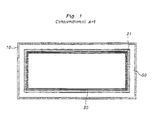
- Fig. 1 is a horizontal cross-sectional view of the conventional art of the heat insulation system for a building.
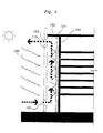
- Fig. 2 is a vertical cross-sectional view of the conventional heat insulation system for a building showing the role of the air flow zone preventing the heat from transferring into the inner space by ventilation of the air-flow zone.
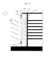
- Fig. 3 is a horizontal cross-sectional view of a heat insulation system for a building according to the present invention.
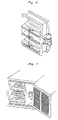
- Fig. 4 and 5 are vertical cross sectional views of a heat insulation system for a building showing the function of air flow zone according to the present invention.
- Fig. 6 is an instrument for ventilation.
- Fig. 7 is an example of in-flow/out-flow entrance in which the ventilation entrance is applied according to the present invention.
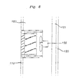
- Fig. 8 is a power driven fan installed at the ventilation instrument.
- Figs. 3 to 5 showing a cross sectional view of the heat insulation system according to the present invention.
- an interior wall 120 surrounding the inner space of the building is constructed.
- a heat insulation material 121 is formed at the exterior surface or the interior surface of the interior wall 120 in order to prevent the inside heat energy from transferring outwards. At the same time the heat transferring from the outside to inside of the building is prevented.
- An exterior wall 110 which decorates the shape of the building is formed with a certain distance from the interior wall 120.
- a heat insulation material 121 is formed at the inside-surface of the exterior wall 110.
- the space formed between the exterior wall 110 and the interior wall 120 is an air-flow zone 150.
- An air inside an air-flow zone 150 serves as an air layer which blocks the heat energy transferred from the outside of the building or which blocks the heat energy transferred from the inner space of the building.
- a building has four facades and each of these facades receive different heat energy according to the different natural environment it faces. According to the situation, one facade can have higher thermal energy than the other facades. In this case, the air in the air-flow zone block of the facade which has high thermal energy is heated up more than others. Therefore, this heated air has to be exhausted to the outside of the air-flow zone 150. On the other hand, it is not necessary to exhaust the air inside the other air-flow zone blocks which have lower thermal energy. So, it is preferred to have an air-flow zone divider 157 which divides the air-flow zone into four air-flow blocks 150a, 150b, 150c and 150d according to the facade or directions.
- the heated air in the south air-flow zone 150c should only be exhausted outwards if the south facade receives the heat energy intensively, and as a result, the insulation is effected.
- Ventilation entrances are formed at the upper and lower part of each blocks of the air-flow zone 150 by forming entrances at the exterior wall 110.
- the air heated inside a certain air-flow block 150a, 150b, 150c or 150d is exhausted through the out-flow(ventilation) entrance 153 formed at the upper part of the air-flow block and at the same time, the external air which has lower temperature than the air inside the air-flow block is flown through the in flow(ventilation) entrance 151 formed at the lower part of the air-flow block.
- Fig. 4 shows a status of an air flow zone exhausting the air in order to enhance the heat insulation of the inside of the building by preventing the outside heat energy from transferring when the outside temperature is high.
- Fig. 5 shows a status of accumulating the heated air by the sun energy at the exterior wall of the building by shutting up the air of the air flow zone in order to enhance the heat insulation of the inside of the building by preventing the inside heat energy of the building from being taken away when the outside temperature is low.
- Fig.6 is an example showing an instrument(e.g. a Mortor Volume Damper) which has an opening and closing function for circulating and blocking the air flow of the air flow zone.
- Fig. 7 shows an entrance in which the air in-flow/out-flow entrance show in Fig. 6.
- Fig. 8 shows a power driven fan 155 which is installed at the out-flow or in-flow entrance.
- the heat insulation is more effective than the conventional arts.
- the present invention suggests a heat insulation system in which a plurality of air-flow blocks are formed and the air-flow blocks are artificially controlled so that some opened blocks effectively prevent the outside heat energy from transferring into the inner space of the building. Furthermore, some blocks in which the air temperature should be preserved as it is and not be lowered are closed so that the air kept in the air-flow blocks can act as an air layer which maintains the inside thermal energy and which prevents the inside thermal energy transferring outside.
Abstract
The present invention relates to a heat insulation system of a
building. Especially, the present invention relates to a heat
insulation system in which artificial changes are possible according
to the need of environment. An object of this invention is to enhance
the heat insulation capability of the building using an air layer
surrounding the building. Another object of the present invention is
to suggest a heat insulation system of a building in which an air
flow zone is formed between the interior wall and the exterior wall
by forming the exterior wall with a certain distance from the
interior wall, and an air-flow zone divider which divides the air
flow zone into a column space according to the direction and facades
of the building.
Description
- The present invention relates to a heat insulation system of a building. Especially, the present invention relates to a heat insulation system in which artificial changes are possible according to the need of environment. According to the heat insulation system of the present invention, a vertical air-flow zones are divided by orientation or each facade of the building and are controlled by opening and closing the air flow zones.
- In general, in order to protect the inside temperature of a building from exterior temperature, heat insulation materials of a certain thickness are formed on the exterior wall of the building. In order to obtain more effective heat insulation, there is a system in which an air-flow zone is further formed on the exterior wall of the building. In case of using this heat insulation system, the heat energy which is transferred from the outside to the inside of the building is re-exhausted to the outside through the air-flow zone especially in summer. The heat energy of the living space of the building is prevented from being transferred to the outside of the building. This means that the air-flow zone plays an important role as a heat insulator of the building. In relation to this conventional system, the applicant has obtained Patents No.186966 and No.196967 from the Korean Intellectual Property Office.
- The above mentioned conventional art is summarized hereinafter with reference to the Fig. 1 and Fig. 2. Construct the
exterior wall 10 of the building and theinterior wall 20 with aheat insulation material 21 on its surface having a certain distance from theexterior wall 10 of the building. As a result, space is formed between theexterior wall 10 and theinterior wall 20 and this space is the air-flow zone 50. An in-flow entrance 51 is formed at the lower part of theexterior wall 10 and an out-flow entrance 53 is formed at the upper part of theexterior wall 10 of the building. When the outside circumstance has a high temperature, i.e., in summer, high thermal energy (for example, the sun energy 80) radiates into the building through theexterior wall 10 from the outside circumstance. The thermal energy flown into the air-flow zone 50 heats up the air inside the air-flow zone 50. The heated air flows out through the out-flow entrance 53 as the warm air rises upward. The air outside the building which has lower temperature than the air in the air-flow zone 50 flows into the air-flow zone 50 through the in-flow entrance 51, Therefore, the thermal energy cannot be transferred to the inner space of the building but re-exhausted to the outside of the building. In order to enhance the function of the air-flow zone 50, a power fan 55 is installed at the out-flow entrance 53 or the in-flow entrance 51. Then the air circulation is more activated, - In the conventional system of the heat insulation of the building, the air-
flow zone 50 is formed at the surface part of the building and this air-flow zone 50 envelopes the surface of the building as one structure. In other words, the air can flow inside the air-flow zone 50 horizontally and vertically as there is no division in all parts of the air-flow zone 50. However, each side of walls have different thermal conditions according to the direction, the amount of the sunshine, the amount of the radiation and the situation of the air streams. As the altitude of the sun differs seasonally, each side of wall of the building receive different thermal energy. For example, in winter when the sun has low altitude, the south side exterior wall receives bigger amount of thermal energy than the other sides. In summer time, the west side exterior wall receives more thermal energy than the south side exterior wall due to the altitude of the sun and duration of radiation received. Therefore, an air-flow block which is separately divided at the air-flow zone according to the direction and facade of the building is needed as the patterns and the numerical values of the absorbed thermal energy through the exterior wall differs by the daily and seasonal changes of the sun energy. - An object of this invention is to enhance the heat insulation capability of the building using an air layer surrounding the building. Another object of the present invention is to suggest a heat insulation system of a building in which an air flow zone is formed between the interior wall and the exterior wall by forming the exterior wall with a certain distance from the interior wall, and an air-flow zone divider which divides the air flow zone into a column space according to the direction and facades of the building.
- Fig. 1 is a horizontal cross-sectional view of the conventional art of the heat insulation system for a building.
- Fig. 2 is a vertical cross-sectional view of the conventional heat insulation system for a building showing the role of the air flow zone preventing the heat from transferring into the inner space by ventilation of the air-flow zone.
- Fig. 3 is a horizontal cross-sectional view of a heat insulation system for a building according to the present invention.
- Fig. 4 and 5 are vertical cross sectional views of a heat insulation system for a building showing the function of air flow zone according to the present invention.
- Fig. 6 is an instrument for ventilation.
- Fig. 7 is an example of in-flow/out-flow entrance in which the ventilation entrance is applied according to the present invention.
- Fig. 8 is a power driven fan installed at the ventilation instrument.
- Hereinafter, we will explain the present invention referring to Figs. 3 to 5, showing a cross sectional view of the heat insulation system according to the present invention. In the present invention, an
interior wall 120 surrounding the inner space of the building is constructed. In some cases, aheat insulation material 121 is formed at the exterior surface or the interior surface of theinterior wall 120 in order to prevent the inside heat energy from transferring outwards. At the same time the heat transferring from the outside to inside of the building is prevented. - An
exterior wall 110 which decorates the shape of the building is formed with a certain distance from theinterior wall 120. In some cases, aheat insulation material 121 is formed at the inside-surface of theexterior wall 110. The space formed between theexterior wall 110 and theinterior wall 120 is an air-flow zone 150. An air inside an air-flow zone 150 serves as an air layer which blocks the heat energy transferred from the outside of the building or which blocks the heat energy transferred from the inner space of the building. - In general, a building has four facades and each of these facades receive different heat energy according to the different natural environment it faces. According to the situation, one facade can have higher thermal energy than the other facades. In this case, the air in the air-flow zone block of the facade which has high thermal energy is heated up more than others. Therefore, this heated air has to be exhausted to the outside of the air-
flow zone 150. On the other hand, it is not necessary to exhaust the air inside the other air-flow zone blocks which have lower thermal energy. So, it is preferred to have an air-flow zone divider 157 which divides the air-flow zone into four air-flow blocks flow zone 150 is divided into four directions, the east air-flow block 150a, the west air-flow block 150b, the south air-flow block 150c and the north air-flow block 150d, the heated air in the south air-flow zone 150c should only be exhausted outwards if the south facade receives the heat energy intensively, and as a result, the insulation is effected. - In order to make the air current, ventilation entrances are formed at the upper and lower part of each blocks of the air-
flow zone 150 by forming entrances at theexterior wall 110. The air heated inside a certain air-flow block entrance 153 formed at the upper part of the air-flow block and at the same time, the external air which has lower temperature than the air inside the air-flow block is flown through the in flow(ventilation)entrance 151 formed at the lower part of the air-flow block. In order to accelerate the air current, it is good to install a power drivenfan 155 at the out-flow entrance 153 or at the in-flow entrance 151. - Fig. 4 shows a status of an air flow zone exhausting the air in order to enhance the heat insulation of the inside of the building by preventing the outside heat energy from transferring when the outside temperature is high. Fig. 5 shows a status of accumulating the heated air by the sun energy at the exterior wall of the building by shutting up the air of the air flow zone in order to enhance the heat insulation of the inside of the building by preventing the inside heat energy of the building from being taken away when the outside temperature is low. Fig.6 is an example showing an instrument(e.g. a Mortor Volume Damper) which has an opening and closing function for circulating and blocking the air flow of the air flow zone. Fig. 7 shows an entrance in which the air in-flow/out-flow entrance show in Fig. 6. Fig. 8 shows a power driven
fan 155 which is installed at the out-flow or in-flow entrance. - According to the present invention, the heat insulation is more effective than the conventional arts. The present invention suggests a heat insulation system in which a plurality of air-flow blocks are formed and the air-flow blocks are artificially controlled so that some opened blocks effectively prevent the outside heat energy from transferring into the inner space of the building. Furthermore, some blocks in which the air temperature should be preserved as it is and not be lowered are closed so that the air kept in the air-flow blocks can act as an air layer which maintains the inside thermal energy and which prevents the inside thermal energy transferring outside.
Claims (4)
- A heat insulation system of a building comprises:an interior wall surrounding inner space of the building;an exterior wall constructed outside of the interior wall with certain distance;an air-flow zone having a space formed between the interior wall and the exterior wall; andan air-flow zone divider dividing the air-flow zone into a plurality of air-flow blocks.
- The heat insulation system for a building according to the claim 1 further comprises a ventilation entrances at the upper part and the lower part of the air-flow block.
- The heat insulation system for a building according to the claim 1 further comprises a heat insulation material which is formed on at least one of the surfaces of the interior wall and the exterior wall.
- The heat insulation system for a building according to the claim 1 further comprises an opening and closing system for a lower and upper air flow entrance.
Priority Applications (1)
| Application Number | Priority Date | Filing Date | Title |
|---|---|---|---|
| EP01100921A EP1223254A1 (en) | 2001-01-16 | 2001-01-16 | An insulation system of a building wherein vertical air-flow zones divided by orientation or each facade of the building is controlled by open-close method |
Applications Claiming Priority (1)
| Application Number | Priority Date | Filing Date | Title |
|---|---|---|---|
| EP01100921A EP1223254A1 (en) | 2001-01-16 | 2001-01-16 | An insulation system of a building wherein vertical air-flow zones divided by orientation or each facade of the building is controlled by open-close method |
Publications (1)
| Publication Number | Publication Date |
|---|---|
| EP1223254A1 true EP1223254A1 (en) | 2002-07-17 |
Family
ID=8176224
Family Applications (1)
| Application Number | Title | Priority Date | Filing Date |
|---|---|---|---|
| EP01100921A Withdrawn EP1223254A1 (en) | 2001-01-16 | 2001-01-16 | An insulation system of a building wherein vertical air-flow zones divided by orientation or each facade of the building is controlled by open-close method |
Country Status (1)
| Country | Link |
|---|---|
| EP (1) | EP1223254A1 (en) |
Cited By (6)
| Publication number | Priority date | Publication date | Assignee | Title |
|---|---|---|---|---|
| WO2011018671A1 (en) * | 2009-08-12 | 2011-02-17 | Ioanis Stamatis | Climatic shielding system for buildings |
| EP2463601A2 (en) | 2010-12-07 | 2012-06-13 | EnerSearch GmbH | Solar fassade element, solar fassade system |
| ITMI20111317A1 (en) * | 2011-07-15 | 2013-01-16 | Uni Politecnica Delle Marche | MODULE FOR COAT AND COAT |
| WO2014072384A1 (en) * | 2012-11-08 | 2014-05-15 | Iis Institute For Independent Studies Gmbh | Building envelope and method for adjusting the temperature in a building |
| WO2014072385A1 (en) * | 2012-11-08 | 2014-05-15 | Iis Institute For Independent Studies Gmbh | Building envelope and method for adjusting the temperature in a building |
| WO2014072386A1 (en) * | 2012-11-08 | 2014-05-15 | Iis Institute For Independent Studies Gmbh | Building envelope and method for adjusting the temperature in a building |
Citations (1)
| Publication number | Priority date | Publication date | Assignee | Title |
|---|---|---|---|---|
| JP2000320033A (en) * | 1999-04-30 | 2000-11-21 | Hinsen Isco Co Ltd | Thermal insulation system for building |
-
2001
- 2001-01-16 EP EP01100921A patent/EP1223254A1/en not_active Withdrawn
Patent Citations (1)
| Publication number | Priority date | Publication date | Assignee | Title |
|---|---|---|---|---|
| JP2000320033A (en) * | 1999-04-30 | 2000-11-21 | Hinsen Isco Co Ltd | Thermal insulation system for building |
Non-Patent Citations (1)
| Title |
|---|
| DATABASE WPI Section PQ Week 200108, Derwent World Patents Index; Class Q43, AN 2001-067381, XP002162258 * |
Cited By (14)
| Publication number | Priority date | Publication date | Assignee | Title |
|---|---|---|---|---|
| WO2011018671A1 (en) * | 2009-08-12 | 2011-02-17 | Ioanis Stamatis | Climatic shielding system for buildings |
| EP2463601A2 (en) | 2010-12-07 | 2012-06-13 | EnerSearch GmbH | Solar fassade element, solar fassade system |
| DE102010054394A1 (en) | 2010-12-07 | 2012-06-14 | Enersearch Gmbh | Solar facade element, solar facade system |
| ITMI20111317A1 (en) * | 2011-07-15 | 2013-01-16 | Uni Politecnica Delle Marche | MODULE FOR COAT AND COAT |
| WO2014072384A1 (en) * | 2012-11-08 | 2014-05-15 | Iis Institute For Independent Studies Gmbh | Building envelope and method for adjusting the temperature in a building |
| WO2014072385A1 (en) * | 2012-11-08 | 2014-05-15 | Iis Institute For Independent Studies Gmbh | Building envelope and method for adjusting the temperature in a building |
| WO2014072386A1 (en) * | 2012-11-08 | 2014-05-15 | Iis Institute For Independent Studies Gmbh | Building envelope and method for adjusting the temperature in a building |
| US9664396B2 (en) | 2012-11-08 | 2017-05-30 | Iis Institute For Independent Studies Gmbh | Building envelope and method for adjusting the temperature in a building |
| US10746413B2 (en) | 2012-11-08 | 2020-08-18 | Iis Institute For Independent Studies Gmbh | Building envelope and method for adjusting the temperature in a building |
| US10962236B2 (en) | 2012-11-08 | 2021-03-30 | Iis Institute For Independent Studies Gmbh | Building envelope and method for adjusting the temperature in a building |
| US11573011B2 (en) | 2012-11-08 | 2023-02-07 | Iis Institute For Independent Studies Zürich Gmbh | Building frame and method for adjusting the temperature in a building |
| US11592189B2 (en) | 2012-11-08 | 2023-02-28 | Iis Institute For Independent Studies Zürich Gmbh | Building frame and method for adjusting the temperature in a building |
| US11608991B2 (en) | 2012-11-08 | 2023-03-21 | Iis Institute For Independent Studies Zürich Gmbg | Heat pipe for a building envelope and method for adjusting the temperature in a building |
| US11629862B2 (en) | 2012-11-08 | 2023-04-18 | Iis Institute For Independent Studies Zürich Gmbh | Building envelope and method for adjusting the temperature in a building |
Similar Documents
| Publication | Publication Date | Title |
|---|---|---|
| US3343474A (en) | Building with a vent device | |
| US6408582B1 (en) | Insulation system of a building wherein vertical air-flow zones divided by orientation or each facade of the building is controlled by open-close method | |
| SI20343A (en) | Air conditioning system for buildings and air-conditioned building, especially a zero energy house | |
| Etzion et al. | Adaptive architecture: integrating low-energy technologies for climate control in the desert | |
| JP3946634B2 (en) | Geothermal use structure | |
| Tatarestaghi et al. | A comparative study of passive design features/elements in Malaysia and passive house criteria in the tropics | |
| EP1223254A1 (en) | An insulation system of a building wherein vertical air-flow zones divided by orientation or each facade of the building is controlled by open-close method | |
| US11619404B2 (en) | Geothermal insulation system and method | |
| KR101650811B1 (en) | Energy saving envelope ventilation structure in renovation building | |
| HU217496B (en) | Method and apparatus for the heating and cooling of buildings and heat insulating wall covering | |
| WO2006028366A1 (en) | Buidling construction | |
| Sobhy et al. | Effect of thermal insulation and ground coupling on thermal load of a modern house in Marrakech | |
| JP2934159B2 (en) | Ventilated structures | |
| KR101913626B1 (en) | Prototype model for hot-arid climate regions | |
| JP2585458B2 (en) | Moisture / hot air discharge and hot air circulation device and building using it | |
| JPH04176937A (en) | Ventilating device for housing | |
| Hamdani et al. | Study of Natural Ventilation through Openings on Buildings under Saharan Climatic Conditions | |
| Lapithis | Passive solar architecture in Cyprus | |
| KR102164513B1 (en) | Eco-friendly non-powered ventilation duct structure | |
| JP3747208B2 (en) | Building | |
| Kaygusuz | Basic principles of passive solar heating for low carbon transition | |
| JP2003202130A (en) | Heating-cooling device | |
| JP4150619B2 (en) | Microclimate design building | |
| Jakhar et al. | Solar passive cooling/heating of building at Bikaner in Rajasthan, India | |
| Pearson | Solar so good. |
Legal Events
| Date | Code | Title | Description |
|---|---|---|---|
| PUAI | Public reference made under article 153(3) epc to a published international application that has entered the european phase |
Free format text: ORIGINAL CODE: 0009012 |
|
| AK | Designated contracting states |
Kind code of ref document: A1 Designated state(s): AT BE CH CY DE DK ES FI FR GB GR IE IT LI LU MC NL PT SE TR |
|
| AX | Request for extension of the european patent |
Free format text: AL;LT;LV;MK;RO;SI |
|
| 17P | Request for examination filed |
Effective date: 20030117 |
|
| AKX | Designation fees paid |
Designated state(s): DE FR GB |
|
| STAA | Information on the status of an ep patent application or granted ep patent |
Free format text: STATUS: THE APPLICATION IS DEEMED TO BE WITHDRAWN |
|
| 18D | Application deemed to be withdrawn |
Effective date: 20070801 |