EP1223083A1 - Device for assisting automobile driver - Google Patents
Device for assisting automobile driver Download PDFInfo
- Publication number
- EP1223083A1 EP1223083A1 EP00961092A EP00961092A EP1223083A1 EP 1223083 A1 EP1223083 A1 EP 1223083A1 EP 00961092 A EP00961092 A EP 00961092A EP 00961092 A EP00961092 A EP 00961092A EP 1223083 A1 EP1223083 A1 EP 1223083A1
- Authority
- EP
- European Patent Office
- Prior art keywords
- moving body
- image
- imaging means
- imaging
- distance
- Prior art date
- Legal status (The legal status is an assumption and is not a legal conclusion. Google has not performed a legal analysis and makes no representation as to the accuracy of the status listed.)
- Granted
Links
Images


Classifications
-
- H—ELECTRICITY
- H04—ELECTRIC COMMUNICATION TECHNIQUE
- H04N—PICTORIAL COMMUNICATION, e.g. TELEVISION
- H04N7/00—Television systems
- H04N7/18—Closed-circuit television [CCTV] systems, i.e. systems in which the video signal is not broadcast
-
- G—PHYSICS
- G06—COMPUTING OR CALCULATING; COUNTING
- G06T—IMAGE DATA PROCESSING OR GENERATION, IN GENERAL
- G06T7/00—Image analysis
- G06T7/50—Depth or shape recovery
- G06T7/55—Depth or shape recovery from multiple images
- G06T7/593—Depth or shape recovery from multiple images from stereo images
-
- G—PHYSICS
- G01—MEASURING; TESTING
- G01C—MEASURING DISTANCES, LEVELS OR BEARINGS; SURVEYING; NAVIGATION; GYROSCOPIC INSTRUMENTS; PHOTOGRAMMETRY OR VIDEOGRAMMETRY
- G01C3/00—Measuring distances in line of sight; Optical rangefinders
- G01C3/02—Details
- G01C3/06—Use of electric means to obtain final indication
- G01C3/08—Use of electric radiation detectors
- G01C3/085—Use of electric radiation detectors with electronic parallax measurement
-
- G—PHYSICS
- G06—COMPUTING OR CALCULATING; COUNTING
- G06T—IMAGE DATA PROCESSING OR GENERATION, IN GENERAL
- G06T7/00—Image analysis
- G06T7/20—Analysis of motion
- G06T7/223—Analysis of motion using block-matching
- G06T7/238—Analysis of motion using block-matching using non-full search, e.g. three-step search
-
- G—PHYSICS
- G06—COMPUTING OR CALCULATING; COUNTING
- G06V—IMAGE OR VIDEO RECOGNITION OR UNDERSTANDING
- G06V20/00—Scenes; Scene-specific elements
- G06V20/50—Context or environment of the image
- G06V20/56—Context or environment of the image exterior to a vehicle by using sensors mounted on the vehicle
- G06V20/58—Recognition of moving objects or obstacles, e.g. vehicles or pedestrians; Recognition of traffic objects, e.g. traffic signs, traffic lights or roads
-
- H—ELECTRICITY
- H04—ELECTRIC COMMUNICATION TECHNIQUE
- H04N—PICTORIAL COMMUNICATION, e.g. TELEVISION
- H04N13/00—Stereoscopic video systems; Multi-view video systems; Details thereof
- H04N13/20—Image signal generators
- H04N13/204—Image signal generators using stereoscopic image cameras
- H04N13/239—Image signal generators using stereoscopic image cameras using two two-dimensional [2D] image sensors having a relative position equal to or related to the interocular distance
-
- H—ELECTRICITY
- H04—ELECTRIC COMMUNICATION TECHNIQUE
- H04N—PICTORIAL COMMUNICATION, e.g. TELEVISION
- H04N7/00—Television systems
- H04N7/18—Closed-circuit television [CCTV] systems, i.e. systems in which the video signal is not broadcast
- H04N7/181—Closed-circuit television [CCTV] systems, i.e. systems in which the video signal is not broadcast for receiving images from a plurality of remote sources
-
- B—PERFORMING OPERATIONS; TRANSPORTING
- B60—VEHICLES IN GENERAL
- B60R—VEHICLES, VEHICLE FITTINGS, OR VEHICLE PARTS, NOT OTHERWISE PROVIDED FOR
- B60R2300/00—Details of viewing arrangements using cameras and displays, specially adapted for use in a vehicle
- B60R2300/10—Details of viewing arrangements using cameras and displays, specially adapted for use in a vehicle characterised by the type of camera system used
- B60R2300/105—Details of viewing arrangements using cameras and displays, specially adapted for use in a vehicle characterised by the type of camera system used using multiple cameras
-
- B—PERFORMING OPERATIONS; TRANSPORTING
- B60—VEHICLES IN GENERAL
- B60R—VEHICLES, VEHICLE FITTINGS, OR VEHICLE PARTS, NOT OTHERWISE PROVIDED FOR
- B60R2300/00—Details of viewing arrangements using cameras and displays, specially adapted for use in a vehicle
- B60R2300/10—Details of viewing arrangements using cameras and displays, specially adapted for use in a vehicle characterised by the type of camera system used
- B60R2300/107—Details of viewing arrangements using cameras and displays, specially adapted for use in a vehicle characterised by the type of camera system used using stereoscopic cameras
-
- B—PERFORMING OPERATIONS; TRANSPORTING
- B60—VEHICLES IN GENERAL
- B60R—VEHICLES, VEHICLE FITTINGS, OR VEHICLE PARTS, NOT OTHERWISE PROVIDED FOR
- B60R2300/00—Details of viewing arrangements using cameras and displays, specially adapted for use in a vehicle
- B60R2300/20—Details of viewing arrangements using cameras and displays, specially adapted for use in a vehicle characterised by the type of display used
- B60R2300/207—Details of viewing arrangements using cameras and displays, specially adapted for use in a vehicle characterised by the type of display used using multi-purpose displays, e.g. camera image and navigation or video on same display
-
- B—PERFORMING OPERATIONS; TRANSPORTING
- B60—VEHICLES IN GENERAL
- B60R—VEHICLES, VEHICLE FITTINGS, OR VEHICLE PARTS, NOT OTHERWISE PROVIDED FOR
- B60R2300/00—Details of viewing arrangements using cameras and displays, specially adapted for use in a vehicle
- B60R2300/30—Details of viewing arrangements using cameras and displays, specially adapted for use in a vehicle characterised by the type of image processing
- B60R2300/303—Details of viewing arrangements using cameras and displays, specially adapted for use in a vehicle characterised by the type of image processing using joined images, e.g. multiple camera images
-
- B—PERFORMING OPERATIONS; TRANSPORTING
- B60—VEHICLES IN GENERAL
- B60R—VEHICLES, VEHICLE FITTINGS, OR VEHICLE PARTS, NOT OTHERWISE PROVIDED FOR
- B60R2300/00—Details of viewing arrangements using cameras and displays, specially adapted for use in a vehicle
- B60R2300/30—Details of viewing arrangements using cameras and displays, specially adapted for use in a vehicle characterised by the type of image processing
- B60R2300/304—Details of viewing arrangements using cameras and displays, specially adapted for use in a vehicle characterised by the type of image processing using merged images, e.g. merging camera image with stored images
- B60R2300/305—Details of viewing arrangements using cameras and displays, specially adapted for use in a vehicle characterised by the type of image processing using merged images, e.g. merging camera image with stored images merging camera image with lines or icons
-
- B—PERFORMING OPERATIONS; TRANSPORTING
- B60—VEHICLES IN GENERAL
- B60R—VEHICLES, VEHICLE FITTINGS, OR VEHICLE PARTS, NOT OTHERWISE PROVIDED FOR
- B60R2300/00—Details of viewing arrangements using cameras and displays, specially adapted for use in a vehicle
- B60R2300/30—Details of viewing arrangements using cameras and displays, specially adapted for use in a vehicle characterised by the type of image processing
- B60R2300/307—Details of viewing arrangements using cameras and displays, specially adapted for use in a vehicle characterised by the type of image processing virtually distinguishing relevant parts of a scene from the background of the scene
-
- B—PERFORMING OPERATIONS; TRANSPORTING
- B60—VEHICLES IN GENERAL
- B60R—VEHICLES, VEHICLE FITTINGS, OR VEHICLE PARTS, NOT OTHERWISE PROVIDED FOR
- B60R2300/00—Details of viewing arrangements using cameras and displays, specially adapted for use in a vehicle
- B60R2300/80—Details of viewing arrangements using cameras and displays, specially adapted for use in a vehicle characterised by the intended use of the viewing arrangement
- B60R2300/8066—Details of viewing arrangements using cameras and displays, specially adapted for use in a vehicle characterised by the intended use of the viewing arrangement for monitoring rearward traffic
-
- B—PERFORMING OPERATIONS; TRANSPORTING
- B60—VEHICLES IN GENERAL
- B60R—VEHICLES, VEHICLE FITTINGS, OR VEHICLE PARTS, NOT OTHERWISE PROVIDED FOR
- B60R2300/00—Details of viewing arrangements using cameras and displays, specially adapted for use in a vehicle
- B60R2300/80—Details of viewing arrangements using cameras and displays, specially adapted for use in a vehicle characterised by the intended use of the viewing arrangement
- B60R2300/8093—Details of viewing arrangements using cameras and displays, specially adapted for use in a vehicle characterised by the intended use of the viewing arrangement for obstacle warning
-
- G—PHYSICS
- G06—COMPUTING OR CALCULATING; COUNTING
- G06T—IMAGE DATA PROCESSING OR GENERATION, IN GENERAL
- G06T2207/00—Indexing scheme for image analysis or image enhancement
- G06T2207/10—Image acquisition modality
- G06T2207/10016—Video; Image sequence
- G06T2207/10021—Stereoscopic video; Stereoscopic image sequence
-
- G—PHYSICS
- G06—COMPUTING OR CALCULATING; COUNTING
- G06T—IMAGE DATA PROCESSING OR GENERATION, IN GENERAL
- G06T2207/00—Indexing scheme for image analysis or image enhancement
- G06T2207/20—Special algorithmic details
- G06T2207/20016—Hierarchical, coarse-to-fine, multiscale or multiresolution image processing; Pyramid transform
-
- G—PHYSICS
- G06—COMPUTING OR CALCULATING; COUNTING
- G06T—IMAGE DATA PROCESSING OR GENERATION, IN GENERAL
- G06T2207/00—Indexing scheme for image analysis or image enhancement
- G06T2207/20—Special algorithmic details
- G06T2207/20021—Dividing image into blocks, subimages or windows
-
- H—ELECTRICITY
- H04—ELECTRIC COMMUNICATION TECHNIQUE
- H04N—PICTORIAL COMMUNICATION, e.g. TELEVISION
- H04N13/00—Stereoscopic video systems; Multi-view video systems; Details thereof
- H04N13/20—Image signal generators
- H04N13/204—Image signal generators using stereoscopic image cameras
- H04N13/207—Image signal generators using stereoscopic image cameras using a single two-dimensional [2D] image sensor
- H04N13/221—Image signal generators using stereoscopic image cameras using a single two-dimensional [2D] image sensor using the relative movement between cameras and objects
-
- H—ELECTRICITY
- H04—ELECTRIC COMMUNICATION TECHNIQUE
- H04N—PICTORIAL COMMUNICATION, e.g. TELEVISION
- H04N13/00—Stereoscopic video systems; Multi-view video systems; Details thereof
- H04N2013/0074—Stereoscopic image analysis
- H04N2013/0081—Depth or disparity estimation from stereoscopic image signals
-
- H—ELECTRICITY
- H04—ELECTRIC COMMUNICATION TECHNIQUE
- H04N—PICTORIAL COMMUNICATION, e.g. TELEVISION
- H04N13/00—Stereoscopic video systems; Multi-view video systems; Details thereof
- H04N2013/0074—Stereoscopic image analysis
- H04N2013/0085—Motion estimation from stereoscopic image signals
Definitions
- the present invention relates to a driving support system for supporting driving of a moving body such as a vehicle by taking an image of environmental conditions of the moving body with a camera and processing camera imagery.
- Japanese Laid-Open Patent Publication No. 9-240397 discloses an annunciator for a vehicle running at the side rear.
- This annunciator detects, on the basis of a camera image taken in the side rear region of the self-vehicle, a moving body present in an adjacent lane and also detects whether or not a white line is present in detecting a moving body, so as to detect another vehicle by integrating the results of these detection.
- closeness between the self-vehicle and another vehicle is judged, so that a driver can be informed when there is a possibility of excessive closeness.
- Japanese Laid-Open Patent Publication No. 7-93693 discloses an object detector for a vehicle.
- This is an object detector for a vehicle capable of correctly distinguishing an object such as a vehicle from a figure or pattern drawn on the road so as to accurately detect the object.
- the movement of an edge point of an object in an image is measured by apparent travel speed measuring means as if it were three-dimensional movement on the road and the measured movement and the speed of the vehicle is compared by object judgment means so as to discriminate the object.
- the method for detecting an obstacle through movement analysis of a camera image is a method generally designated as motion stereo, in which change of an image in accordance with change of a visual point through movement is analyzed so as to obtain three-dimensional information of the camera image.
- This method has a problem that the change of the image in accordance with the change of the visual point is small in a camera image taken in a moving direction.
- this method is applied to, for example, a vehicle, there arises a problem that the sensitivity of the detection is lowered when an object is closer to the forward or backward region along the moving direction.
- the technique of movement analysis is used for obtaining the movement of an object on a screen, when the imaging device is installed on a vehicle, the screen is vibrated due to jolt of the vehicle, and hence, the movement cannot be accurately obtained.
- the driver when an approaching object is detected, it is significant how the driver is informed of the approaching object. In the case where an alarm sound or the like is used, the alarm sound may surprise the driver, which may cause a mistake in the driving. Also, error detection of an approaching object may obstacle safe driving of the driver. Thus, it is a significant problem how the driver is informed of an approaching object. In respect to a warning to the driver, the first conventional example merely describes that the driver is informed of excessive closeness. In the second conventional example, no description is made on the method for informing the driver of a detected obstacle.
- an object of the invention is providing a driving support system in which a driver can directly confirm environmental conditions such as an approaching object and an obstacle so as to reduce burdens of the driver.
- the system for supporting driving of a moving body of this invention comprises a plurality of imaging means installed on the moving body for taking camera images of the rear of the moving body; and detection means for detecting movement of an object present in the rear of the moving body based on the camera images of the plurality of imaging means, and the plurality of imaging means have, in camera images thereof, an overlap area that includes an area in the vicinity of a vanishing point and in which imaging areas of first imaging means and second imaging means overlap with each other, and the detection means obtains a stereo parallax between the first imaging means and the second imaging means in the overlap area, and obtains a distance to the object on the basis of the obtained stereo parallax.
- the detection means of the driving support system of this invention preferably detects flows corresponding to movement with time of an image in the imaging area of the first imaging means excluding the overlap area, and detects movement of the object present in the rear of the moving body on the basis of the detected flows.
- the driving supporting system of this invention preferably further comprises image synthesizing means for generating an image representing the rear of the moving body through image synthesis using the camera images of the plurality of imaging means.
- the driving supporting system of this invention preferably further comprises danger level determining means for determining a possibility of collision of the moving body with an approaching object from the rear of the moving body on the basis of information output from the detection means and for outputting an indicator signal when it is determined that there is a strong possibility of the collision; and external warning means for providing a warning to the rear of the moving body when the indicator signal is output from the danger level determining means.
- danger level determining means for determining a possibility of collision of the moving body with an approaching object from the rear of the moving body on the basis of information output from the detection means and for outputting an indicator signal when it is determined that there is a strong possibility of the collision; and passenger protecting means for taking measure to protect a passenger of the moving body when the indicator signal is output from the danger level determining means.
- another system for supporting driving of a moving body of this invention comprises imaging means installed on the moving body for taking a camera image of a surrounding region of the moving body; image generating means for converting the camera image of the imaging means into an image seen from a visual point positioned differently from the imaging means; and detecting means for detecting a distance from the moving body to an object imaged in the camera image, and the image generating means corrects distortion of an image of the object by using the distance detected by the detection means in converting the image.
- the imaging means is plural in number
- the plural imaging means have, in camera images thereof, an overlap area in which imaging areas of first imaging means and second imaging means overlap with each other
- the detection means obtains a stereo parallax between the first imaging means and the second imaging means in the overlap area, and obtains a distance to the object on the basis of the obtained stereo parallax.
- the detection means of this driving support system preferably obtains a distance to the object on the basis of flows corresponding to movement with time of the camera image.
- Still another system for supporting driving of a moving body of this invention comprises imaging means installed on the moving body for taking a camera image of a surrounding region of the moving body; and detection means for obtaining flows corresponding to movement with time on the basis of the camera image of the imaging means and for detecting movement of an object present in the surrounding region of the moving body on the basis of the flows, and the detection means obtains, as preparation for detecting the movement of the object, an offset estimated value from each of the obtained flows and cancels the offset estimated value from each of the flows as a vibration component derived from jolt of the moving body.
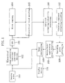
- FIG. 1 is a block diagram for showing the structure of a driving support system (moving body image display system) according to Embodiment 1 of the invention.
- a reference numeral 101 denotes imaging means provided on a moving body
- a reference numeral 102 denotes hierarchical image generating means
- a reference numeral 103 denotes an LPF (low-pass filter)
- a reference numeral 104 denotes block sampling means
- a reference numeral 105 denotes hierarchical block matching means
- a reference numeral 106 denotes sub-pixel estimating/reliability determining means
- a reference numeral 107 denotes vibration component extracting/canceling means
- a reference numeral 108 denotes vanishing point calculating means
- a reference numeral 109 denotes moving body/approaching object detecting means
- a reference numeral 110 denotes image synthesizing means
- a reference numeral 111 denotes a display device.
- the imaging means 101 is, for example, a camera, and is provided on a rear portion, for example, on a rear panel of a vehicle so that an image of the rear of the vehicle can be taken.
- a display device 111 a display dedicated to this system or a liquid crystal monitor for car navigation may be used.
- the object of the moving body image display system of this embodiment is mainly reducing burdens of a driver by directly and comprehensively warning and displaying an object approaching from the rear that can be a danger in changing the driving course.
- the operation of the moving body image display system of this embodiment will now be described with reference to FIGS. 2 through 13 .
- the imaging means 101 takes an image (herein of 320 pixels x 240 pixels) of the rear of the self-vehicle as shown in FIG. 2A .
- This camera image includes obstacles such as a building 11 and a roadside tree 12 and moving bodies such as other vehicles 13 and 14 running behind. In FIG. 2 , these obstacles and moving bodies are schematically expressed.
- This camera image is input to the hierarchical image generating means 102 and the image synthesizing means 110.
- the hierarchical image generating means 102 generates a primary upper image (of 160 x 120 pixels) by adding each of 2 x 2 pixels of the input image. Furthermore, a secondary upper image (of 80 x 60 pixels) is similarly generated from the primary upper image. These three kinds of images are output to the LPF 103 as hierarchical images.
- the LPF 103 conducts LPF processing for 3 x 3 pixels on each of the input hierarchical images.
- the hierarchical block matching means 105 obtains, from the image of the upper hierarchy, an SAD (a sum of absolute differences) through block matching in a range of 5 x 5 pixels, and further obtains a motion vector on the basis of a point where the SAD is minimum. With respect to a block of the image of the lower hierarchy, a motion vector is further obtained in a range of 5 x 5 pixels with a motion vector obtained in a block of the higher hierarchy disposed in the same position as the center.
- SAD sum of absolute differences
- the sub-pixel estimating/reliability determining means 106 estimates, by using the motion vector obtained in the image of the lowest hierarchy (camera image) and the SAD, a motion vector at accuracy of a sub-pixel with one or less pixel on the basis of values of the SAD at the SAD minimum point and eight points around the SAD minimum point. Also, the sub-pixel estimating/reliability determining means 106 determines the reliability of the motion vector in the block.
- the flows FL in the camera image will now be described with reference to FIG. 3 .
- the aforementioned flows FL are obtained at edge portions of the image.
- a direction reverse to the running direction of the vehicle of FIG. 3 corresponds to a vanishing point VP on the screen shown in FIG. 4A .
- An object standing still on the ground has a flow FL directing toward the vanishing point VP on the screen. Accordingly, an area on the screen having a flow FL not directing to the vanishing point VP (such as a rectangular area 202 ) can be extracted as a moving body or an approaching object.
- the vibration component extracting/canceling means 107 extracts and cancels a vibration component caused by the jolt of the vehicle by integrally processing the obtained motion vectors.
- the vanishing point calculating means 108 obtains the vanishing point VP of the flows FL of the image accompanied by the movement of the car. Specifically, as shown in FIG. 4A , the vanishing point VP is obtained as a point to which most of the points on the entire image direct.
- the moving body/approaching object detecting means 109 extracts, as a moving body/approaching object candidate block, a block having a motion vector different from the flow FL directing to the vanishing point VP obtained by the vanishing point calculating means 108. Furthermore, moving body/approaching object candidate blocks close to one another are linked, so that an area where the moving body/approaching object is present like a rectangular area 202 can be extracted as a moving body as shown in FIG. 4B.
- FIG. 5 is a flowchart for explaining the operation.
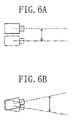
- a vehicle not only moves in the running direction but also jolts in the vertical direction owing to the influence of bumps of the road and the like.
- the influence of the vertical jolt of the vehicle on the imaging means appears as a positional change as shown in FIG. 6A and an imaging direction change as shown in FIG. 6B.
- the vertical positional change as shown in FIG. 6A is very small as compared with a positional change along the running direction of the vehicle because the frame gap of an image signal is very small. Also, a change of the position of the imaging means is largely varied in its influence depending upon the distance to an object, and largely affects a close object but minimally affects a far object. The distance to a rear object monitored in this embodiment is several meters through several tens meters, which is sufficiently far. Accordingly, in this case, the imaging direction change shown in FIG. 6B alone is considered without considering the influence of the vertical positional change.
- the imaging direction change is not varied in its influence depending upon the distance to an object, and when the angle of the change is very small, it can be assumed as a vertical offset Vdy , which is constant in the entire screen, with respect to each motion vector on the screen.
- the offset (0, Vdy) is extracted as the vibration component, so as to be cancelled from the detected motion vector (Vx, Vy).
- the motion vector (V0x, V0y) directed toward the vanishing point VP is obtained in the still background portion.
- a motion vector (Vx, Vy) is input (S11).
- a uniform area where there is no figure, such as the sky motion vectors are previously excluded because of lack of the reliability thereof, and motion vectors with reliability alone are input.
- a virtual vanishing point (x0, y0) obtained by assuming that the vehicle runs straight forward can be previously obtained because it can be determined on a predetermined point on the screen on the basis of the installation angle of the imaging means 101 (S12).
- Vdy can be obtained from one motion vector.
- the input motion vectors include a large number of motion vectors with regard to image areas apart form the still background portion such as a moving body.
- a motion vector with regard to the still background portion includes an error. Therefore, the offset Vdy of the motion vector is estimated through statistical processing. Specifically, as shown in FIG. 7, with respect to each motion vector, Vdy is obtained in accordance with the aforementioned formula, and the frequency of each Vdy is calculated, so that Vdy with the highest frequency can be determined as an ultimate offset estimated value (S14, S15 and S16).
- an error ( ⁇ Vnx, ⁇ Vny) is assumed with respect to one motion vector, and a small error ( ⁇ nx, ⁇ ny) is assumed with respect to the position on the screen.
- the offset Vdy is obtained with respect to one motion vector as shown in FIG. 7A.
- the error ( ⁇ Vnx, ⁇ Vny) of the motion vector is considered with respect to this offset, distributions as shown in FIGS. 7B and 7C are obtained, and when the small error ( ⁇ nx, ⁇ ny) of the position on the screen is considered, distributions as shown in FIGS. 7D and 7E are obtained.
- FIGS. 7F Through convolution integral of the distributions of FIGS. 7B through 7E, a distribution as shown in FIG. 7F can be obtained.
- the vanishing point calculating means 10 8 of FIG. 1 cancels the estimated offset and then obtains an actual vanishing point again.
- the calculated vanishing point is largely different from the virtual vanishing point.
- the subsequent moving body/approaching object detecting processing is suspended, and an image is synthesized by using a result obtained from a previous frame and the synthesized image is displayed.
- the processing is determined to be normal, and the moving body/approaching object detecting means 109 conducts the following operation:
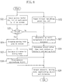
- FIG. 8 is a flowchart for showing the specific operation of the moving body/approaching object detecting means 109 .
- a motion vector (Vx, Vy) with respect to each point (x, y) on the screen and the virtual vanishing point (x0, y0) are input (S21 and S22).
- this determination is made depending upon whether or not the distribution of Vdy (of FIG. 7F) obtained in the vibration component extraction in consideration of the error ( ⁇ Vnx, ⁇ Vny) of the motion vector and the small error ( ⁇ nx, ⁇ ny) of the position on the screen accords with the offset estimated value.
- the point of this motion vector is determined as a moving body.
- the point of this motion vector is determined as the still background.
- motion vectors FL1 each determined as a moving body are detected in respective portions of the moving body on the screen. Therefore, an area including these motion vectors FL1 is grouped as shown in FIG. 10B, so as to generate a rectangular moving body area 202 (S24). A distance from the vehicle to this moving body is then estimated on the position of the lower end UE of the moving body area 202.
- FIG. 11A is a diagram for showing a default distance value in an imaging range of the imaging means 101.
- a first area AR1 below a predetermined position in the camera image is assumed to be present on a road surface RS
- a second area AR2 above the predetermined position is assumed to be away from the imaging means 101 by a predetermined distance DD (of, for example, 50 m).
- DD of, for example, 50 m
- an estimated distance to the road surface RS is stored as the default distance value
- the predetermined distance DD is stored as the default distance value.
- the distance is estimated on the basis of the lower end UE of the moving body area 202 included in the first area AR1 by assuming that the object is in contact with the road surface RS at the lower end UE.
- the distance to the moving body area estimated at this point is stored in a memory.
- the object included in the moving body area is determined as an approaching object (S26).
- a distance Z is calculated on the basis of the size of the vector (with the offset canceled) by the following formula (S27):
- Z dZ * r / dr
- dZ is a travel length of the vehicle between the frames
- r is a distance from the vanishing point VP on the screen
- dr sqrt (Vx 2 + (Vy - Vdy) 2 )
- the distance Z obtained at this point is compared with the distance to the road surface stored as the default distance value (S28).
- an object positioned higher than the road surface such as a roadside tree OB of FIG. 12B , is determined as an obstacle.
- a motion vector is obtained in the vicinity of the vanishing point, but its size is very small. Therefore, when the distance Z is obtained in the aforementioned manner, a value representing that the object is positioned below the road surface may be obtained. Since no object is generally present below the road surface, such a motion vector is determined as a moving body, so as to be processed through the moving body area extracting processing S24.
- an obstacle, a moving body, an approaching object and their distances in the image are obtained on the basis of the respective motion vectors of the points on the screen (S29), and the resultant information is output to the image synthesizing means 110 .
- the image synthesizing means 110 synthesizes a frame 203 of the rectangular area 202 to be lighted in red on the camera image input from the imaging means 101 as shown in FIG. 13 and outputs the synthesized image to the display device 111 .
- the display device 111 displays an image obtained by laterally inverting the synthesized image so as to be in the same phase as an image on a rearview mirror.
- the driver sees the display image as shown in FIG. 13 so as to recognize the approaching of the approaching object owing to the lighting of the red frame 203. Specifically, the driver sees the camera image so as to confirm the environmental conditions and can naturally pay attention to an approaching object that should be particularly careful about without being surprised by an alarm sound or the like.
- an approaching moving body alone is displayed with a flashing red frame in this embodiment
- a method for drawing attention of the driver is not limited to this but another color may be used or the red frame may be displayed without flashing.
- the image of an approaching object displayed on the display device 111 is moving downward, it can be understood that the object is approaching the moving body, and when the image is moving upward, it can be understood that the object is moving away from the moving body.
- the grasp of the environmental conditions by the driver can be further supported by displaying the distance itself or changing the display in accordance with the distance.
- the color of the frame may be changed in accordance with the distance, for example, the frame is displayed in green when the distance is 50 m or more, in yellow when the distance is less than 50 m and 20 m or more and in red when the distance is less than 20 m, or the distance value itself may be displayed in the upper right portion of the moving body area.
- FIG. 14 is a block diagram for showing the structure of a moving body image display system serving as a driving support system according to Embodiment 2 of the invention.
- like reference numerals are used to refer to like elements shown in FIG. 1 so as to omit the detailed description.
- Composing elements different from those shown in FIG. 1 are second imaging means 401 provided separately from first imaging means 101, hierarchical block stereo-matching means 405 , 3D information estimating/obstacle detecting means 409 and 3D image synthesizing means 410 serving as image synthesizing means or image generating means.
- the composing elements 102 through 109 , 405 and 409 together form detection means.
- An object of the moving body image display system of this embodiment is accurately detecting an approaching object or an obstacle close to a vanishing point having motion vectors (flows) difficult to accurately obtain.
- the operation of the moving body image display system of this embodiment will now be described with reference to FIGS. 15 through 21 .
- FIG. 15 is a schematic diagram of a self-vehicle and the surrounding area seen from above.
- two imaging means 101 and 401 are installed on a rear portion of the vehicle apart from each other in the horizontal direction.
- the imaging means are disposed so as to have an overlap area OL where a first imaging range VA1 of the first imaging means 101 serving as one imaging means and a second imaging range VA2 of the second imaging means 401 serving as another imaging means overlap with each other.
- the imaging means are disposed as shown in FIG. 15 in order to take an image of and monitor the rear of the vehicle with a wide visual field by using a camera having a general lens with a limited visual angle.
- a camera having a general lens with a limited visual angle When the plural imaging means are thus disposed, an image with a large visual field can be taken without using a special lens such as a fisheye lens. Also, by using the plural imaging means, the resolution of the obtained image can be kept high.
- the two imaging ranges are preferably overlapped in consideration of occlusion accompanying the positions.
- the hierarchical image generating means 102 , the LPF 103 , the block sampling means 10 4 and the hierarchical block matching means 105 carry out the same processing as that of Embodiment 1 on each camera image input from the imaging means 101 and 401 , so as to obtain flows (motion vectors).
- FIGS. 16A and 16B are diagrams in which the flows obtained in the aforementioned manner are overlapped on the camera images obtained by the imaging means 101 and 401 , respectively.
- OL denotes an overlap area between the camera images.
- flows with respect to still objects such as a building and a tree are indicated by solid arrows, and flows with respect to moving bodies such as a car are indicated by broken arrows.
- the flows with respect to the still objects are flows directing toward the vanishing point VP owing to the movement of the self-vehicle.
- the size of each of these flows is in proportion to the speed of the self-vehicle and the distance to the vanishing point VP on the screen. Therefore, a flow in the vicinity of the vanishing point VP has a small size, and hence is difficult to detect.
- the hierarchical block stereo-matching means 405 carries out stereo-analysis of the overlap area OL of the two images of FIGS. 16A and 16B so as to obtain a stereo parallax. Since the vanishing point VP is formed right behind in the running direction of the vehicle, the imaging means 101 and 401 can be easily installed so that the overlap area OL includes the vanishing point VP in the camera image.
- FIG. 16C is a diagram obtained by overlapping the two images of FIGS. 16A and 16B.
- dislocation VD in the image of the vehicle corresponds to the obtained stereo parallax.
- the stereo parallax VD is caused in substantially the horizontal direction. Therefore, an SAD (a sum of absolute differences) is obtained through block matching in a range of horizontal 5 pixels x vertical 3 pixels from the image of the higher hierarchy, and a stereo parallax is obtained from a point where the SAD is minimum. With respect to the image of the lower hierarchy, a stereo parallax is further obtained in a range of horizontal 5 pixels x vertical 3 pixels with a stereo parallax obtained in a block in the same position in the image of the higher hierarchy as the center.
- SAD sum of absolute differences
- the sub-pixel estimating/reliability determining means 106 estimates, by using the motion vector obtained in the image of the lowest hierarchy (camera image) and the SAD, a motion vector at accuracy of one or less sub-pixel based on the SAD minimum point and SAD values at eight points around the SAD minimum point. Also, it determines the reliability of the motion vector in the block.
- the processing for the motion vectors is applied to the stereo parallax VD obtained by the hierarchical block stereo-matching means 405 in the completely same manner, so as to estimate a stereo parallax at accuracy of a sub-pixel and determine the reliability of the stereo parallax.
- a distance from the imaging means to the object can be obtained through the principle of the trigonometrical survey. Also, on the basis of a flow corresponding to the movement with time of an image, by assuming that, for example, the object is still on the ground, the distance from the imaging means to the object can be obtained in relation to the running speed.
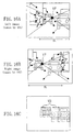
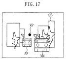
- the 3D information estimating/obstacle detecting means 409 estimates three-dimensional information with respect to the two camera images as shown in FIG. 17 , and detects, as an obstacle OB , an area on the screen estimated to be at a predetermined height or more above the ground.
- the moving body/approaching object detecting means 109 extracts, as a moving body/approaching object candidate block, a block having a motion vector different from a flow directing toward the vanishing point VP , and extracts a moving body MM as shown in FIG. 17 by linking moving body/approaching object candidate blocks close to one another. Furthermore, when it is determined that the distance to an obstacle present in an area in the vicinity of the vanishing point VP is approaching on the basis of the three-dimensional information obtained from the 3D information estimating/obstacle detecting means 409, this object is extracted as an approaching object AP as shown in FIG. 17.
- the 3D image synthesizing means 410 utilizes the three-dimensional information obtained from the 3D information estimating/obstacle detecting means 409 so as to synthesize the two camera images input from the imaging means 101 and 401 . Furthermore, it displays, on the synthesized image, areas of the moving body MM and the approaching object AP surrounded with, for example, lighting red frames, and displays the obstacle OB surrounded with, for example, a green frame, and they are output to the display device 111 . At this point, the display device 111 displays an image obtained by laterally inverting the synthesized image to be in the same phase as an image on a rearview mirror.
- the driver sees the display image as shown in FIG. 17 , so as to be informed of approaching of the moving body MM and the approaching object AP owing to the lighting of the red frames, and can directly and easily grasp from which direction and to what extent the approaching object AP is approaching the self-vehicle. Furthermore, the driver can directly and easily grasp the presence and the position of the obstacle owing to the display of the green frame.
- Embodiment 2 detection in an area in the vicinity of the vanishing point on the screen is compensated by the stereo analysis of the overlap area OL obtained by the two cameras, and hence, detection can be carried out at high sensitivity.
- the 3D image synthesizing means 410 utilizes the three-dimensional information obtained from the 3D information estimating/obstacle detecting means 409 so as to appropriately inform the driver of the information of the approaching object and the obstacle. The method will now be described.
- Embodiment 1 when a camera image synthesized with the information of an approaching object is seen, a distance in a depth direction in the screen should be determined based on the apparent size of the object on the synthesized image.
- the imaging means when installed on a vehicle, it cannot be provided in a position higher than the height of the vehicle and should be directed substantially horizontal direction for allowing a rather far place to come in sight. As a result, the distance to an approaching object is unavoidably in the depth direction in the screen.
- a technique to change the visual point of a synthesized image as disclosed in Japanese Patent Application No. 10-217261 devised by the present inventors can be employed.
- plural camera images around a vehicle are assumed to be obtained by three-dimensionally taking images of the ground, so as to generate a synthesized image from a new visual point, for example, as if it were looked down from the sky.
- a distance between the vehicle and another object is in proportion to the distance on the screen, and hence, it can be intuitively grasped.
- the 3D image synthesizing means 410 of this embodiment utilizes the aforementioned technique to convert the camera images obtained by the imaging means 101 and 401 into a synthesized image seen from a visual point higher than the actual installation positions of the imaging means. In order to attain a large visual field up to a far place, a visual point looking obliquely downward is preferred to a visual point looking right below.
- FIG. 18A shows the position of a virtual visual point VVP for obtaining such a synthesized image.
- the virtual visual point VVP is positioned above the imaging means 101 and directed to an obliquely downward direction behind the vehicle.
- the synthesized image seen from the virtual visual point VVP can be generated from the actual camera image as shown in FIG. 18B.
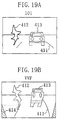
- the synthesized image seen from the virtual visual point VVP is as shown in FIG. 19B.
- a white line 411 and the like actually present on the road surface at the default distance are synthesized in accurate positions also on the synthesized image, and since it is an image seen from above, the distance is enhanced to be easily grasped.
- a tree 412 and a vehicle 413 that are not actually present on the road surface are elongated to be unnaturally distorted on the synthesized image.
- the synthesized image shown in FIG. 19B includes an area 414 outside the image actually taken.
- the three-dimensional information obtained from the 3D information estimating/obstacle detecting means 409 is utilized, so that the distortion of a vehicle and the like caused on the synthesized image can be largely improved. This will be described with reference to FIGS. 20 and 21 .
- the three-dimensional information obtained from the 3D information estimating/obstacle detecting means 409 is utilized for detecting an obstacle and an approaching object present above the ground. Therefore, an area of the obstacle or the approaching object is synthesized in accordance with the three-dimensional information as shown in FIG. 20A, and hence, even when an image seen from the virtual visual point VVP is synthesized, the synthesized image can be a natural image free from distortion.
- the actual distances RD from the imaging means 101 are detected, and therefore, the areas are synthesized in positions determined in consideration of the actual distances RD on the synthesized image. Accordingly, as shown in FIG. 20B , the tree 412 and the vehicle 413 not actually present on the road surface are synthesized not on the basis of the default distances but on the basis of the actual distances RD , and hence, they are not elongated but can be natural on the synthesized image.
- the synthesized image in the synthesized image, a white line and the like that are actually present on the road surface at the default distances are synthesized in accurate positions, and also with respect to a tree and a vehicle that are not actually present on the road surface, natural images can be obtained. Furthermore, since the synthesized image is an image seen from above, an image in which a distance can be easily grasped can be presented to the driver.
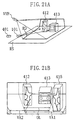
- FIG. 21 is a diagram of generation of a synthesized image from the camera images of the two imaging means 101 and 401.
- FIG. 21A also in this case, with respect to a tree 412 and a vehicle 413 that are not actually present on the road surface, the actual distances RD from the imaging means 101 and 401 are detected, and hence, the areas are synthesized in positions determined in consideration of the actual distances RD on the synthesized image.
- a synthesized image as shown in FIG. 21B is obtained.
- VA1 and VA2 respectively denote areas corresponding to the visual field ranges of the imaging means 101 and 401
- OL denotes an overlap area where the visual field ranges are overlapped.
- an image with a wide visual angle is synthesized. Furthermore, in an area outside the overlap area OL, a distance can be also obtained based on a flow because it is away from the vanishing point, and therefore, for example, a tree 415 can be synthesized in a position in consideration of the distance.
- Embodiment 2 A modification of Embodiment 2 will now be described with reference to FIGS. 22 and 23 .
- FIG. 22 is a diagram for showing an example of the arrangement of the imaging means according to this modification.
- the two imaging means 101 and 401 are installed to be apart from each other at a distance k not in the horizontal direction but in the vertical direction.
- the first imaging area VA1 of the imaging means 101 and the second imaging area VA2 of the imaging means 401 are overlapped with each other so as to have the overlap area OL .
- a stereo-analysis area ST is provided in the overlap area between the two imaging areas, and movement analysis areas MA1 and MA2 are provided in other portions.
- an image of a vehicle running on the road which is the principal object of this invention, includes a larger number of horizontal edges, such as the bumper and a line of the bonnet, as compared with other edges, and hence can be easily detected.
- an approaching object and an obstacle can be detected in the same manner as in the aforementioned embodiment, and an image of an approaching object or an obstacle can be three-dimensionally synthesized to be displayed.
- the two imaging means and the virtual visual point are arranged in the vertical direction, and hence, a vertical parallax is enhanced in the synthesized image. Furthermore, in an area where the number of horizontal edges is so small that the stereo parallax VD cannot be accurately obtained, the accuracy of the synthesized image is also lowered, but since the number of horizontal edges is small, unnaturalness caused by positional dislocation is minimally recognized. Accordingly, the synthesized image is very natural as a whole, and in an area where there are horizontal edges (such as an area where another vehicle is imaged), a synthesized image in which information on a position in the depth direction is enhanced can be generated.
- the actual accuracy for detecting a parallax is 0.3 through 1 pixel, and assuming that a desired distance for detecting an approaching object is 30 through 70 m and that the field angle of the imaging means is 60 through 120 degrees, the distance between the imaging means may be approximately 7 through 20 cm according to rough calculation.
- the imaging means are provided to be apart from each other at a comparatively small distance of approximately 7 through 20 cm, an approaching object can be detected, and hence, the system can be installed on a vehicle with more ease.
- a region behind a vehicle is described as a principal monitoring region in Embodiments 1 and 2, which does not limit the invention.
- a region in front or on a side of the vehicle may be the monitoring region so as to generate an image of the region in front or on the side of the vehicle.
- FIG. 24 is a block diagram for showing the structure of a driving support system according to Embodiment 3 of the invention.
- composing elements different from those shown in FIG. 14 are danger level determining means 501 , external warning means 502 and passenger protecting means 503.
- an overlap area between plural imaging means 101 and 401 is stereo-analyzed by the hierarchical stereo-matching means 405 , so as to accurately detect an approaching object right behind the vehicle, which is conventionally difficult to detect.
- a conventional system for detecting an approaching object does not cover an object approaching from right behind not only because such an approaching object is difficult to detect merely by movement detection but also because there are few methods for avoiding collision or the like after the detection of such an approaching object.
- collision can be easily avoided by warning not to change the course to the adjacent lane.
- it is necessary to make positive movement, such as to evade forward by increasing the speed or to change the course to another lane. In either case, there arises another risk such as collision with another vehicle or object other than the approaching object.
- the danger level determining means 501 determines a possibility of collision with this approaching object on the basis of time up to the collision, change of the speed of the approaching object and the like.
- an indicator signal is output.
- the external warning means 502 receives the indicator signal and gives a warning behind by, for example, automatically lighting a brake light. This warning is not limited to the lighting of a brake light but may be radiation or flash of another light provided to face backward, an alarm sound, or a warning using electric waves such as a radio.
- the passenger protecting means 503 takes measure to protect passengers such as winding up a seat belt or preparation for the operation of an air bag system.
- passengers such as winding up a seat belt or preparation for the operation of an air bag system.
- various preparation such as the preparation for the operation and detection of heads of passengers can be carried out, so as to definitely protect the passengers.
- the detection means for an approaching object of this embodiment is not limited to the means utilizing the stereo-images and the movement analysis but may be another means using, for example, radar or laser.
- the invention can be easily applied to a moving body other than a vehicle, such as a ship, an airplane and a train.
- installation positions and the number of plural imaging means are not limited to those described herein.
- the functions of the detection means and the image generating means of the driving support system of this invention may be wholly or partially realized by dedicated hardware or software.
- a recording medium or a transfer medium storing a program for making a computer execute the whole or a part of the functions of the detection means and the image generating means of the driving support system of this invention may be used.
- an approaching object can be detected without being influenced by vibration derived from jolt of a vehicle. Also, when the stereo-analysis using a plurality of imaging means is utilized together, an approaching object right behind that causes a small movement change in an image can be detected.
- the driver can directly confirm the positional relationship and the environmental conditions. Furthermore, when an image is converted into an image seen from a higher visual point looking obliquely downward, the distance to an approaching object can be displayed more simply.
- the present invention provides a driving support system for reducing burdens of a driver.
Landscapes
- Engineering & Computer Science (AREA)
- Physics & Mathematics (AREA)
- Multimedia (AREA)
- General Physics & Mathematics (AREA)
- Theoretical Computer Science (AREA)
- Signal Processing (AREA)
- Computer Vision & Pattern Recognition (AREA)
- Electromagnetism (AREA)
- Radar, Positioning & Navigation (AREA)
- Remote Sensing (AREA)
- Image Analysis (AREA)
- Closed-Circuit Television Systems (AREA)
- Image Processing (AREA)
- Traffic Control Systems (AREA)
- Air Bags (AREA)
- Automotive Seat Belt Assembly (AREA)
- Studio Devices (AREA)
- Fittings On The Vehicle Exterior For Carrying Loads, And Devices For Holding Or Mounting Articles (AREA)
- Length Measuring Devices By Optical Means (AREA)
- Measurement Of Optical Distance (AREA)
Abstract
Description
Claims (9)
- A system for supporting driving of a moving body comprising:wherein said plurality of imaging means have, in camera images thereof, an overlap area that includes an area in the vicinity of a vanishing point and in which imaging areas of first imaging means and second imaging means overlap with each other, anda plurality of imaging means installed on said moving body for taking camera images of the rear of said moving body; anddetection means for detecting movement of an object present in the rear of said moving body based on said camera images of said plurality of imaging means,
said detection means obtains a stereo parallax between said first imaging means and said second imaging means in said overlap area, and obtains a distance to said object on the basis of said obtained stereo parallax. - The driving supporting system of Claim 1,
wherein said detection means detects flows corresponding to movement with time of an image in the imaging area of said first imaging means excluding said overlap area, and detects movement of said object present in the rear of said moving body on the basis of said detected flows. - The driving supporting system of Claim 1, further comprising image synthesizing means for generating an image representing the rear of said moving body through image synthesis using said camera images of said plurality of imaging means.
- The driving supporting system of Claim 1, further comprising:danger level determining means for determining a possibility of collision of said moving body with an approaching object from the rear of said moving body on the basis of information output from said detection means and for outputting an indicator signal when it is determined that there is a strong possibility of the collision; andexternal warning means for providing a warning to the rear of said moving body when said indicator signal is output from said danger level determining means.
- The driving supporting system of Claim 1, further comprising:danger level determining means for determining a possibility of collision of said moving body with an approaching object from the rear of said moving body on the basis of information output from said detection means and for outputting an indicator signal when it is determined that there is a strong possibility of the collision; andpassenger protecting means for taking measure to protect a passenger of said moving body when said indicator signal is output from said danger level determining means.
- A system for supporting driving of a moving body comprising:wherein said image generating means corrects distortion of an image of said object by using said distance detected by said detection means in converting said image.imaging means installed on said moving body for taking a camera image of a surrounding region of said moving body;image generating means for converting said camera image of said imaging means into an image seen from a visual point positioned differently from said imaging means; anddetecting means for detecting a distance from said moving body to an object imaged in said camera image,
- The driving supporting system of Claim 6,
wherein said imaging means is plural in number,
said plural imaging means have, in camera images thereof, an overlap area in which imaging areas of first imaging means and second imaging means overlap with each other, and
said detection means obtains a stereo parallax between said first imaging means and said second imaging means in said overlap area, and obtains a distance to said object on the basis of said obtained stereo parallax. - The system for supporting driving of a moving body of Claim 6,
wherein said detection means obtains a distance to said object on the basis of flows corresponding to movement with time of said camera image. - A system for supporting driving of a moving body comprising:wherein said detection means obtains, as preparation for detecting the movement of said object, an offset estimated value from each of said obtained flows and cancels said offset estimated value from each of said flows as a vibration component derived from jolt of said moving body.imaging means installed on said moving body for taking a camera image of a surrounding region of said moving body; anddetection means for obtaining flows corresponding to movement with time on the basis of said camera image of said imaging means and for detecting movement of an object present in the surrounding region of said moving body on the basis of said flows,
Applications Claiming Priority (3)
| Application Number | Priority Date | Filing Date | Title |
|---|---|---|---|
| JP26562999 | 1999-09-20 | ||
| JP26562999 | 1999-09-20 | ||
| PCT/JP2000/006393 WO2001021446A1 (en) | 1999-09-20 | 2000-09-20 | Device for assisting automobile driver |
Publications (3)
| Publication Number | Publication Date |
|---|---|
| EP1223083A1 true EP1223083A1 (en) | 2002-07-17 |
| EP1223083A4 EP1223083A4 (en) | 2003-03-19 |
| EP1223083B1 EP1223083B1 (en) | 2004-03-17 |
Family
ID=17419801
Family Applications (1)
| Application Number | Title | Priority Date | Filing Date |
|---|---|---|---|
| EP00961092A Expired - Lifetime EP1223083B1 (en) | 1999-09-20 | 2000-09-20 | Device for assisting automobile driver |
Country Status (7)
| Country | Link |
|---|---|
| US (1) | US6993159B1 (en) |
| EP (1) | EP1223083B1 (en) |
| JP (2) | JP3300340B2 (en) |
| KR (1) | KR100466458B1 (en) |
| CN (1) | CN1160210C (en) |
| DE (1) | DE60009114T2 (en) |
| WO (1) | WO2001021446A1 (en) |
Cited By (13)
| Publication number | Priority date | Publication date | Assignee | Title |
|---|---|---|---|---|
| EP1087626A3 (en) * | 1999-09-22 | 2003-08-13 | Fuji Jukogyo Kabushiki Kaisha | Distance correcting apparatus in a surrounding monitoring system |
| EP1442918A3 (en) * | 2003-01-31 | 2004-09-08 | Robert Bosch Gmbh | Method for displaying vehicle specific information |
| EP1548685A3 (en) * | 2003-12-26 | 2005-09-14 | Fuji Jukogyo Kabushiki Kaisha | Vehicle driving assist system |
| US7158664B2 (en) * | 2001-11-09 | 2007-01-02 | Honda Giken Kogyo Kabushiki Kaisha | Image recognition apparatus |
| WO2007034314A1 (en) * | 2005-09-26 | 2007-03-29 | Toyota Jidosha Kabushiki Kaisha | Vehicle surroundings information output system and method for outputting vehicle surroundings information |
| EP2068269A3 (en) * | 2004-04-08 | 2009-10-07 | Mobileye Technologies Limited | Collision warning system |
| EP2240796A4 (en) * | 2008-01-22 | 2012-07-11 | Magna Int Inc | USING A SINGLE CAMERA FOR MULTIPLE DRIVER ASSISTANCE SERVICES, PARKING AID, HITCH ASSISTANCE AND HATCH PROTECTION |
| CN102632840A (en) * | 2011-02-09 | 2012-08-15 | 本田技研工业株式会社 | Vehicle periphery monitoring apparatus |
| EP3139340A1 (en) * | 2015-09-02 | 2017-03-08 | SMR Patents S.à.r.l. | System and method for visibility enhancement |
| DE102010052942B4 (en) | 2009-11-19 | 2021-11-04 | Robert Bosch Gmbh | Backward looking multifunctional camera system |
| EP3150961B1 (en) * | 2014-05-28 | 2023-01-04 | Kyocera Corporation | Stereo camera device and vehicle provided with stereo camera device |
| US11648876B2 (en) | 2015-09-02 | 2023-05-16 | SMR Patents S.à.r.l. | System and method for visibility enhancement |
| EP4216537A4 (en) * | 2020-09-17 | 2024-03-20 | JVCKenwood Corporation | IMAGE PROCESSING DEVICE AND IMAGE PROCESSING PROGRAM |
Families Citing this family (94)
| Publication number | Priority date | Publication date | Assignee | Title |
|---|---|---|---|---|
| JP3620710B2 (en) * | 2000-07-28 | 2005-02-16 | 日本ビクター株式会社 | Imaging device |
| DE10131196A1 (en) | 2001-06-28 | 2003-01-16 | Bosch Gmbh Robert | Device for the detection of objects, people or the like |
| DE10218228A1 (en) * | 2002-04-24 | 2003-11-06 | Volkswagen Ag | Motor vehicle video camera operational checking method in which video data are subjected to plausibility testing in conjunction with other sensor data, such as yaw rate, transverse acceleration, vehicle speed, etc. |
| JP3904988B2 (en) * | 2002-06-27 | 2007-04-11 | 株式会社東芝 | Image processing apparatus and method |
| JP2004147210A (en) * | 2002-10-25 | 2004-05-20 | Matsushita Electric Ind Co Ltd | Driving support device |
| JP2004240480A (en) * | 2003-02-03 | 2004-08-26 | Matsushita Electric Ind Co Ltd | Driving support device |
| KR20050036179A (en) * | 2003-10-15 | 2005-04-20 | 현대자동차주식회사 | A forward area monitoring device of vehicle and method thereof |
| CN1910626A (en) * | 2003-11-11 | 2007-02-07 | 特希尼库斯股份公司 | Device for recording driving and/or traffic conditions and method for evaluating said recorded data |
| JP3980565B2 (en) * | 2004-02-16 | 2007-09-26 | 松下電器産業株式会社 | Driving assistance device |
| US7406182B2 (en) * | 2004-03-31 | 2008-07-29 | Fujifilm Corporation | Image capturing apparatus, image capturing method, and machine readable medium storing thereon image capturing program |
| JP2005311868A (en) | 2004-04-23 | 2005-11-04 | Auto Network Gijutsu Kenkyusho:Kk | Vehicle periphery visual recognition device |
| JP4586416B2 (en) * | 2004-05-20 | 2010-11-24 | 日産自動車株式会社 | Driving assistance device |
| EP2182730B1 (en) * | 2004-06-15 | 2020-05-20 | Panasonic Intellectual Property Management Co., Ltd. | Monitor and vehicle periphery monitor |
| WO2006009257A1 (en) * | 2004-07-23 | 2006-01-26 | Matsushita Electric Industrial Co., Ltd. | Image processing device and image processing method |
| EP1779061B1 (en) * | 2004-08-04 | 2013-11-06 | Intergraph Software Technologies Company | Method and computer program product for preparing and comparing composite images with non-uniform resolution |
| JP2006054662A (en) * | 2004-08-11 | 2006-02-23 | Mitsubishi Electric Corp | Driving assistance device |
| US7639841B2 (en) * | 2004-12-20 | 2009-12-29 | Siemens Corporation | System and method for on-road detection of a vehicle using knowledge fusion |
| US7609290B2 (en) * | 2005-01-28 | 2009-10-27 | Technology Advancement Group, Inc. | Surveillance system and method |
| KR100782811B1 (en) * | 2005-02-04 | 2007-12-06 | 삼성전자주식회사 | Stereo video synthesizing method and apparatus having different formats according to frequency characteristics of video, transmission and reception method of video, reproduction method and video of video |
| WO2006092431A1 (en) * | 2005-03-03 | 2006-09-08 | Continental Teves Ag & Co. Ohg | Method and device for avoiding a collision as a vehicle is changing lanes |
| JP4544028B2 (en) * | 2005-05-13 | 2010-09-15 | 日産自動車株式会社 | In-vehicle image processing apparatus and image processing method |
| JP4626400B2 (en) * | 2005-05-25 | 2011-02-09 | 日産自動車株式会社 | Overhead image display device and overhead image display method |
| KR100666276B1 (en) * | 2005-07-13 | 2007-01-10 | 현대자동차주식회사 | Lane departure warning method of vehicle using vanishing point |
| SE529304C2 (en) * | 2005-09-06 | 2007-06-26 | Gm Global Tech Operations Inc | Method and system for improving road safety |
| FR2891934B1 (en) * | 2005-10-12 | 2008-01-18 | Valeo Electronique Sys Liaison | DEVICE FOR PROCESSING VIDEO DATA FOR A MOTOR VEHICLE |
| JP2007148835A (en) * | 2005-11-28 | 2007-06-14 | Fujitsu Ten Ltd | Object distinction device, notification controller, object distinction method and object distinction program |
| JP4757085B2 (en) * | 2006-04-14 | 2011-08-24 | キヤノン株式会社 | IMAGING DEVICE AND ITS CONTROL METHOD, IMAGE PROCESSING DEVICE, IMAGE PROCESSING METHOD, AND PROGRAM |
| JP4846426B2 (en) * | 2006-04-20 | 2011-12-28 | パナソニック株式会社 | Vehicle perimeter monitoring device |
| JP4847884B2 (en) * | 2007-01-31 | 2011-12-28 | オプトレックス株式会社 | Obstacle detection device, vehicle display device, and obstacle detection method |
| JP5271511B2 (en) * | 2007-06-14 | 2013-08-21 | 富士通テン株式会社 | Driving support device and image display device |
| JP5337170B2 (en) | 2008-02-08 | 2013-11-06 | グーグル インコーポレイテッド | Panorama camera with multiple image sensors using timed shutters |
| JP4513871B2 (en) * | 2008-02-15 | 2010-07-28 | ソニー株式会社 | Image processing method, image processing program, and image processing apparatus |
| JP4986069B2 (en) * | 2008-03-19 | 2012-07-25 | マツダ株式会社 | Ambient monitoring device for vehicles |
| DE102008060684B4 (en) * | 2008-03-28 | 2019-05-23 | Volkswagen Ag | Method and device for automatic parking of a motor vehicle |
| KR100929689B1 (en) * | 2008-09-08 | 2009-12-03 | 재단법인대구경북과학기술원 | Vehicle accident recorder using stereo image information and its control method |
| KR100971731B1 (en) | 2008-11-07 | 2010-07-22 | 주식회사 케이제이몰 | Image processing apparatus and method in a vehicle image storage system |
| KR100997617B1 (en) | 2008-11-20 | 2010-12-01 | 재단법인대구경북과학기술원 | Incident recording devices, methods and systems for transportation |
| JP4553072B1 (en) * | 2009-03-31 | 2010-09-29 | コニカミノルタホールディングス株式会社 | Image integration apparatus and image integration method |
| JP4733756B2 (en) * | 2009-04-28 | 2011-07-27 | 本田技研工業株式会社 | Vehicle periphery monitoring device |
| DE102009038406B4 (en) * | 2009-08-24 | 2017-10-05 | Volkswagen Ag | Method and device for measuring the environment of a motor vehicle |
| JP5039765B2 (en) * | 2009-09-17 | 2012-10-03 | 日立オートモティブシステムズ株式会社 | Vehicle control device |
| CN102577372B (en) * | 2009-09-24 | 2015-06-10 | 松下电器产业株式会社 | Driving support display device |
| JP2011118482A (en) | 2009-11-30 | 2011-06-16 | Fujitsu Ten Ltd | In-vehicle device and recognition support system |
| US8751191B2 (en) | 2009-12-22 | 2014-06-10 | Panasonic Corporation | Action analysis device and action analysis method |
| CN102275558B (en) * | 2010-06-12 | 2013-01-23 | 财团法人车辆研究测试中心 | Dual vision front vehicle safety warning device and method thereof |
| JP5609597B2 (en) * | 2010-12-02 | 2014-10-22 | 富士通株式会社 | Contact possibility detection device, contact possibility detection method, and program |
| JP5695405B2 (en) * | 2010-12-10 | 2015-04-08 | 東芝アルパイン・オートモティブテクノロジー株式会社 | Image processing apparatus for vehicle and image processing method for vehicle |
| KR101243108B1 (en) | 2010-12-30 | 2013-03-12 | 주식회사 와이즈오토모티브 | Apparatus and method for displaying rear image of vehicle |
| JP2012155655A (en) * | 2011-01-28 | 2012-08-16 | Sony Corp | Information processing device, notification method, and program |
| WO2013042767A1 (en) * | 2011-09-21 | 2013-03-28 | 本田技研工業株式会社 | Apparatus for monitoring surroundings of vehicle |
| DE102011084554A1 (en) * | 2011-10-14 | 2013-04-18 | Robert Bosch Gmbh | Method for displaying a vehicle environment |
| CN103085716A (en) * | 2011-10-31 | 2013-05-08 | 鸿富锦精密工业(深圳)有限公司 | Traffic accident preventing system and traffic accident preventing method |
| JP5760999B2 (en) * | 2011-12-02 | 2015-08-12 | トヨタ自動車株式会社 | Image processing apparatus and image processing method |
| KR101340014B1 (en) * | 2011-12-09 | 2013-12-10 | 에스엘 주식회사 | Apparatus and method for providing location information |
| JP5414947B2 (en) | 2011-12-27 | 2014-02-12 | パナソニック株式会社 | Stereo camera |
| CN103448652B (en) * | 2012-06-04 | 2016-06-15 | 宏达国际电子股份有限公司 | Traffic warning method and electronic device thereof |
| CN103522952A (en) * | 2012-07-06 | 2014-01-22 | 昆达电脑科技(昆山)有限公司 | Alarming device for reminding dangers in driving process and method thereof |
| JP5695000B2 (en) * | 2012-08-13 | 2015-04-01 | 本田技研工業株式会社 | Vehicle periphery monitoring device |
| TWI494234B (en) * | 2012-08-24 | 2015-08-01 | Altek Autotronics Corp | Driving assistance system and method of initialing thereof |
| JP6084434B2 (en) * | 2012-10-31 | 2017-02-22 | クラリオン株式会社 | Image processing system and image processing method |
| CN104118380B (en) * | 2013-04-26 | 2017-11-24 | 富泰华工业(深圳)有限公司 | driving detecting system and method |
| CN105190694B (en) | 2013-05-16 | 2019-01-22 | 索尼公司 | Image processing apparatus, image processing method and program |
| US10171775B1 (en) | 2013-05-31 | 2019-01-01 | Vecna Technologies, Inc. | Autonomous vehicle vision system |
| KR20150051389A (en) * | 2013-11-04 | 2015-05-13 | 현대모비스 주식회사 | Method for processing image and Apparatus for the same |
| EP3085074B1 (en) * | 2013-12-19 | 2020-02-26 | Intel Corporation | Bowl-shaped imaging system |
| US9449234B2 (en) * | 2014-03-31 | 2016-09-20 | International Business Machines Corporation | Displaying relative motion of objects in an image |
| JP6264173B2 (en) | 2014-04-18 | 2018-01-24 | 富士通株式会社 | Normality determination method for imaging direction, imaging device attachment state evaluation program, and imaging device attachment state evaluation device |
| JP6299373B2 (en) * | 2014-04-18 | 2018-03-28 | 富士通株式会社 | Imaging direction normality determination method, imaging direction normality determination program, and imaging direction normality determination apparatus |
| JP6299371B2 (en) | 2014-04-18 | 2018-03-28 | 富士通株式会社 | Imaging direction inclination detection method, imaging direction inclination detection program, and imaging direction inclination detection apparatus |
| US9355547B2 (en) | 2014-05-22 | 2016-05-31 | International Business Machines Corporation | Identifying a change in a home environment |
| US9613274B2 (en) * | 2014-05-22 | 2017-04-04 | International Business Machines Corporation | Identifying an obstacle in a route |
| CN104200213B (en) * | 2014-08-12 | 2018-07-17 | 合肥工业大学 | One kind being based on multipart vehicle checking method |
| JP5949861B2 (en) * | 2014-09-05 | 2016-07-13 | トヨタ自動車株式会社 | Vehicle approaching object detection device and vehicle approaching object detection method |
| JP6356586B2 (en) * | 2014-11-28 | 2018-07-11 | 株式会社デンソー | Vehicle travel control device |
| CN104477126A (en) * | 2014-12-12 | 2015-04-01 | 常州博显汽车电子有限公司 | Active safety belt device for vehicle |
| CN107111949B (en) * | 2014-12-26 | 2020-04-10 | 横滨橡胶株式会社 | Anti-collision system and anti-collision method |
| CN107004364B (en) * | 2014-12-26 | 2020-04-10 | 横滨橡胶株式会社 | Anti-collision system and anti-collision method |
| JP6564577B2 (en) * | 2015-02-16 | 2019-08-21 | 修一 田山 | Proximity alarm device for automobiles |
| KR101639722B1 (en) * | 2015-05-26 | 2016-07-15 | 주식회사 피엘케이 테크놀로지 | Correction apparatus and method for vanishing point |
| US10489926B2 (en) * | 2015-08-31 | 2019-11-26 | Mitsubishi Electric Corporation | Image processing device, image processing method, and program |
| WO2017099047A1 (en) * | 2015-12-09 | 2017-06-15 | 一 笠原 | Position information identification method, position information identification device, and position information identification program |
| KR102565485B1 (en) * | 2016-01-11 | 2023-08-14 | 한국전자통신연구원 | Server and Method for Providing City Street Search Service |
| DE102016104730A1 (en) * | 2016-03-15 | 2017-09-21 | Connaught Electronics Ltd. | Method for detecting an object along a road of a motor vehicle, computing device, driver assistance system and motor vehicle |
| US20170297488A1 (en) * | 2016-04-19 | 2017-10-19 | GM Global Technology Operations LLC | Surround view camera system for object detection and tracking |
| KR102529119B1 (en) | 2016-06-27 | 2023-05-04 | 삼성전자주식회사 | Method and device for acquiring depth information of object and recordimg medium thereof |
| IT201600094858A1 (en) * | 2016-09-21 | 2018-03-21 | St Microelectronics Srl | PROCEDURE FOR A LOW COST ADVANCED CROSS TRAFFIC ALERT, CORRESPONDING PROCESSING SYSTEM, CROSS TRAFFIC ALERT AND VEHICLE SYSTEM |
| US20180374237A1 (en) * | 2017-06-23 | 2018-12-27 | Canon Kabushiki Kaisha | Method, system and apparatus for determining a pose for an object |
| KR101849326B1 (en) * | 2017-08-31 | 2018-04-17 | 주식회사 핀텔 | Camera system for vehicle |
| JP6958147B2 (en) * | 2017-09-07 | 2021-11-02 | トヨタ自動車株式会社 | Image display device |
| JP2020086491A (en) * | 2018-11-15 | 2020-06-04 | 株式会社リコー | Information processing apparatus, information processing system, and information processing method |
| CN109263557B (en) * | 2018-11-19 | 2020-10-09 | 威盛电子股份有限公司 | Vehicle blind area detection method |
| CN110435650A (en) * | 2019-08-22 | 2019-11-12 | 爱驰汽车有限公司 | Emergency avoidance method, system, equipment and storage medium are collided after vehicle |
| CN111813116A (en) * | 2020-07-09 | 2020-10-23 | 海南发控智慧环境建设集团有限公司 | Obstacle avoidance auxiliary system based on three-dimensional model |
| KR102759176B1 (en) * | 2022-08-17 | 2025-01-23 | 한국자동차연구원 | Wireless camera system and operating method thereof |
Family Cites Families (30)
| Publication number | Priority date | Publication date | Assignee | Title |
|---|---|---|---|---|
| JPS4851444A (en) * | 1971-11-02 | 1973-07-19 | ||
| DE2215576C3 (en) * | 1972-03-30 | 1988-09-29 | Ernst Leitz Wetzlar Gmbh, 6330 Wetzlar | Device for measuring, controlling and/or displaying the movement of land vehicles |
| CH564778A5 (en) | 1972-03-30 | 1975-07-31 | Leitz Ernst Gmbh | |
| DE3637165A1 (en) | 1986-10-31 | 1988-05-05 | Rainer Ashauer | METHOD AND DEVICE FOR PREVENTING CRASHES, IN PARTICULAR FOR MOTOR VEHICLES IN ROAD TRAFFIC |
| US5670935A (en) | 1993-02-26 | 1997-09-23 | Donnelly Corporation | Rearview vision system for vehicle including panoramic view |
| JP3239521B2 (en) * | 1993-03-30 | 2001-12-17 | トヨタ自動車株式会社 | Mobile object recognition device |
| JPH06333200A (en) | 1993-05-21 | 1994-12-02 | Toshiba Corp | On-vehicle supervisory system |
| JPH0717328A (en) | 1993-06-30 | 1995-01-20 | Mitsubishi Motors Corp | Peripheral recognition assistance device for vehicles |
| JP3063481B2 (en) | 1993-09-21 | 2000-07-12 | 日産自動車株式会社 | Vehicle object detection device |
| JP3381351B2 (en) | 1993-12-24 | 2003-02-24 | 日産自動車株式会社 | Ambient situation display device for vehicles |
| US6118475A (en) * | 1994-06-02 | 2000-09-12 | Canon Kabushiki Kaisha | Multi-eye image pickup apparatus, and method and apparatus for measuring or recognizing three-dimensional shape |
| JP3117902B2 (en) | 1995-07-28 | 2000-12-18 | 株式会社アイチコーポレーション | Work range control device for aerial work vehicles |
| US5886744A (en) * | 1995-09-08 | 1999-03-23 | Intel Corporation | Method and apparatus for filtering jitter from motion estimation video data |
| JP3485135B2 (en) | 1995-09-27 | 2004-01-13 | 矢崎総業株式会社 | Rear side monitoring device for vehicles |
| JP3765862B2 (en) | 1996-02-15 | 2006-04-12 | 本田技研工業株式会社 | Vehicle environment recognition device |
| JPH09249083A (en) * | 1996-03-15 | 1997-09-22 | Toshiba Corp | Mobile object identification device and method |
| JP3456843B2 (en) * | 1996-07-22 | 2003-10-14 | 富士通株式会社 | Front inter-vehicle distance measurement device |
| JPH10222665A (en) * | 1997-01-31 | 1998-08-21 | Fujitsu Ten Ltd | Image recognition device |
| JPH10341430A (en) * | 1997-06-06 | 1998-12-22 | Yazaki Corp | Detection of front vehicle and system for monitoring front of vehicle |
| JP3841323B2 (en) * | 1997-07-07 | 2006-11-01 | 矢崎総業株式会社 | Vehicle rear side monitoring method and vehicle rear side monitoring device |
| JPH1142988A (en) * | 1997-07-25 | 1999-02-16 | Yazaki Corp | Vehicle rear side monitoring method and vehicle rear side monitoring device |
| JP3464368B2 (en) * | 1997-07-25 | 2003-11-10 | 矢崎総業株式会社 | Rear side monitoring device for vehicles |
| JPH11213295A (en) * | 1998-01-28 | 1999-08-06 | Kansei Corp | Vehicle interruption detection circuit and rear-end collision alarming device using the same |
| US6674430B1 (en) * | 1998-07-16 | 2004-01-06 | The Research Foundation Of State University Of New York | Apparatus and method for real-time volume processing and universal 3D rendering |
| JP4031122B2 (en) * | 1998-09-30 | 2008-01-09 | 本田技研工業株式会社 | Object detection device using difference image |
| JP3596314B2 (en) * | 1998-11-02 | 2004-12-02 | 日産自動車株式会社 | Object edge position measuring device and moving object traffic judging device |
| JP2000207693A (en) | 1999-01-08 | 2000-07-28 | Nissan Motor Co Ltd | In-vehicle obstacle detection device |
| JP2000242797A (en) | 1999-02-18 | 2000-09-08 | Toyota Motor Corp | Image motion detection method and object detection device |
| JP2000241120A (en) * | 1999-02-23 | 2000-09-08 | Fanuc Ltd | Measuring apparatus |
| US6535114B1 (en) * | 2000-03-22 | 2003-03-18 | Toyota Jidosha Kabushiki Kaisha | Method and apparatus for environment recognition |
-
2000
- 2000-09-20 CN CNB008128669A patent/CN1160210C/en not_active Expired - Lifetime
- 2000-09-20 EP EP00961092A patent/EP1223083B1/en not_active Expired - Lifetime
- 2000-09-20 US US10/088,593 patent/US6993159B1/en not_active Expired - Lifetime
- 2000-09-20 WO PCT/JP2000/006393 patent/WO2001021446A1/en not_active Ceased
- 2000-09-20 DE DE60009114T patent/DE60009114T2/en not_active Expired - Lifetime
- 2000-09-20 JP JP2001524839A patent/JP3300340B2/en not_active Expired - Lifetime
- 2000-09-20 KR KR10-2002-7003649A patent/KR100466458B1/en not_active Expired - Lifetime
-
2002
- 2002-02-22 JP JP2002046169A patent/JP4091775B2/en not_active Expired - Lifetime
Cited By (29)
| Publication number | Priority date | Publication date | Assignee | Title |
|---|---|---|---|---|
| EP1087626A3 (en) * | 1999-09-22 | 2003-08-13 | Fuji Jukogyo Kabushiki Kaisha | Distance correcting apparatus in a surrounding monitoring system |
| US7158664B2 (en) * | 2001-11-09 | 2007-01-02 | Honda Giken Kogyo Kabushiki Kaisha | Image recognition apparatus |
| US7474765B2 (en) * | 2001-11-09 | 2009-01-06 | Honda Giken Kogyo Kabushiki Kaisha | Image recognition apparatus |
| EP1442918A3 (en) * | 2003-01-31 | 2004-09-08 | Robert Bosch Gmbh | Method for displaying vehicle specific information |
| US7940301B2 (en) | 2003-12-26 | 2011-05-10 | Fuji Jukogyo Kabushiki Kaisha | Vehicle driving assist system |
| EP1548685A3 (en) * | 2003-12-26 | 2005-09-14 | Fuji Jukogyo Kabushiki Kaisha | Vehicle driving assist system |
| US9916510B2 (en) | 2004-04-08 | 2018-03-13 | Mobileye Vision Technologies Ltd. | Collision warning system |
| US10579885B2 (en) | 2004-04-08 | 2020-03-03 | Mobileye Vision Technologies Ltd. | Collision warning system |
| EP2068269A3 (en) * | 2004-04-08 | 2009-10-07 | Mobileye Technologies Limited | Collision warning system |
| US9656607B2 (en) | 2004-04-08 | 2017-05-23 | Mobileye Vision Technologies Ltd. | Collision warning system |
| US9168868B2 (en) | 2004-04-08 | 2015-10-27 | Mobileye Vision Technologies Ltd. | Collision Warning System |
| US9096167B2 (en) | 2004-04-08 | 2015-08-04 | Mobileye Vision Technologies Ltd. | Collision warning system |
| US8879795B2 (en) | 2004-04-08 | 2014-11-04 | Mobileye Vision Technologies Ltd. | Collision warning system |
| US8861792B2 (en) | 2004-04-08 | 2014-10-14 | Mobileye Technologies Ltd. | Collison warning system |
| US7847678B2 (en) | 2005-09-26 | 2010-12-07 | Toyota Jidosha Kabushiki Kaisha | Vehicle surroundings information output system and method for outputting vehicle surroundings information |
| WO2007034314A1 (en) * | 2005-09-26 | 2007-03-29 | Toyota Jidosha Kabushiki Kaisha | Vehicle surroundings information output system and method for outputting vehicle surroundings information |
| EP2240796A4 (en) * | 2008-01-22 | 2012-07-11 | Magna Int Inc | USING A SINGLE CAMERA FOR MULTIPLE DRIVER ASSISTANCE SERVICES, PARKING AID, HITCH ASSISTANCE AND HATCH PROTECTION |
| DE102010052942B4 (en) | 2009-11-19 | 2021-11-04 | Robert Bosch Gmbh | Backward looking multifunctional camera system |
| EP2487648A1 (en) * | 2011-02-09 | 2012-08-15 | Honda Motor Co., Ltd. | Vehicle periphery monitoring apparatus |
| CN102632840A (en) * | 2011-02-09 | 2012-08-15 | 本田技研工业株式会社 | Vehicle periphery monitoring apparatus |
| US8848056B2 (en) | 2011-02-09 | 2014-09-30 | Honda Motor Co., Ltd. | Vehicle periphery monitoring apparatus |
| CN102632840B (en) * | 2011-02-09 | 2015-05-06 | 本田技研工业株式会社 | Vehicle periphery monitoring apparatus |
| EP2665040A3 (en) * | 2011-02-09 | 2013-12-11 | Honda Motor Co., Ltd. | Vehicle periphery monitoring apparatus |
| EP3150961B1 (en) * | 2014-05-28 | 2023-01-04 | Kyocera Corporation | Stereo camera device and vehicle provided with stereo camera device |
| EP3139340A1 (en) * | 2015-09-02 | 2017-03-08 | SMR Patents S.à.r.l. | System and method for visibility enhancement |
| US10846833B2 (en) | 2015-09-02 | 2020-11-24 | SMR Patents S.à.r.l. | System and method for visibility enhancement |
| US11648876B2 (en) | 2015-09-02 | 2023-05-16 | SMR Patents S.à.r.l. | System and method for visibility enhancement |
| EP4216537A4 (en) * | 2020-09-17 | 2024-03-20 | JVCKenwood Corporation | IMAGE PROCESSING DEVICE AND IMAGE PROCESSING PROGRAM |
| US12284438B2 (en) | 2020-09-17 | 2025-04-22 | Jvckenwood Corporation | Image processing device, image processing method and non-transitory computer-readable recording medium |
Also Published As
| Publication number | Publication date |
|---|---|
| KR20020033817A (en) | 2002-05-07 |
| CN1373720A (en) | 2002-10-09 |
| DE60009114T2 (en) | 2004-08-05 |
| DE60009114D1 (en) | 2004-04-22 |
| KR100466458B1 (en) | 2005-01-14 |
| EP1223083A4 (en) | 2003-03-19 |
| US6993159B1 (en) | 2006-01-31 |
| JP2002335524A (en) | 2002-11-22 |
| CN1160210C (en) | 2004-08-04 |
| JP3300340B2 (en) | 2002-07-08 |
| WO2001021446A1 (en) | 2001-03-29 |
| EP1223083B1 (en) | 2004-03-17 |
| JP4091775B2 (en) | 2008-05-28 |
Similar Documents
| Publication | Publication Date | Title |
|---|---|---|
| EP1223083B1 (en) | Device for assisting automobile driver | |
| KR100909741B1 (en) | Monitoring device, monitoring method | |
| JP3776094B2 (en) | Monitoring device, monitoring method and monitoring program | |
| JPWO2001021446A1 (en) | Driving assistance devices | |
| CN102081861B (en) | On-vehicle device and recognition support system | |
| US8199975B2 (en) | System and method for side vision detection of obstacles for vehicles | |
| JP4861574B2 (en) | Driving assistance device | |
| JP4809019B2 (en) | Obstacle detection device for vehicle | |
| US20080205706A1 (en) | Apparatus and method for monitoring a vehicle's surroundings | |
| CN101763640B (en) | Online calibration processing method for vehicle-mounted multi-view camera viewing system | |
| US20170140542A1 (en) | Vehicular image processing apparatus and vehicular image processing system | |
| CN104859538A (en) | Vision-based object sensing and highlighting in vehicle image display systems | |
| JPH06293236A (en) | Travel environment monitoring device | |
| CN101101333A (en) | Apparatus and method for generating driver assistance information for a moving vehicle | |
| Ruder et al. | Highway lane change assistant | |
| CN108973858A (en) | For ensuring the device of travel route safety | |
| JP5083443B2 (en) | Driving support device and method, and arithmetic device | |
| JP4475015B2 (en) | Vehicle periphery monitoring device and vehicle periphery monitoring method | |
| CN113246859B (en) | Electronic rearview mirror with driving auxiliary system warning function | |
| US8213683B2 (en) | Driving support system with plural dimension processing units | |
| JP4601505B2 (en) | Top-view image generation apparatus and top-view image display method | |
| JP2007318460A (en) | Vehicle upper viewpoint image displaying apparatus | |
| JP4506299B2 (en) | Vehicle periphery monitoring device | |
| JP6999239B2 (en) | Image processing device and image processing method | |
| US20250303965A1 (en) | Visual assistance display apparatus, visual assistance display system, and visual assistance display method |
Legal Events
| Date | Code | Title | Description |
|---|---|---|---|
| PUAI | Public reference made under article 153(3) epc to a published international application that has entered the european phase |
Free format text: ORIGINAL CODE: 0009012 |
|
| 17P | Request for examination filed |
Effective date: 20020419 |
|
| AK | Designated contracting states |
Kind code of ref document: A1 Designated state(s): AT BE CH CY DE DK ES FI FR GB GR IE IT LI LU MC NL PT SE |
|
| RIN1 | Information on inventor provided before grant (corrected) |
Inventor name: ISHII, HIROFUMI Inventor name: MORIMURA, ATSUSHI Inventor name: OKAMOTO, SHUSAKU Inventor name: NAKAGAWA, MASAMICHI |
|
| RIC1 | Information provided on ipc code assigned before grant |
Free format text: 7B 60R 21/00 A, 7B 60R 1/02 B, 7B 60R 21/01 B |
|
| A4 | Supplementary search report drawn up and despatched |
Effective date: 20030203 |
|
| 17Q | First examination report despatched |
Effective date: 20030416 |
|
| GRAP | Despatch of communication of intention to grant a patent |
Free format text: ORIGINAL CODE: EPIDOSNIGR1 |
|
| GRAS | Grant fee paid |
Free format text: ORIGINAL CODE: EPIDOSNIGR3 |
|
| GRAA | (expected) grant |
Free format text: ORIGINAL CODE: 0009210 |
|
| AK | Designated contracting states |
Kind code of ref document: B1 Designated state(s): DE FR GB |
|
| REG | Reference to a national code |
Ref country code: GB Ref legal event code: FG4D |
|
| REG | Reference to a national code |
Ref country code: IE Ref legal event code: FG4D |
|
| REF | Corresponds to: |
Ref document number: 60009114 Country of ref document: DE Date of ref document: 20040422 Kind code of ref document: P |
|
| ET | Fr: translation filed | ||
| PLBE | No opposition filed within time limit |
Free format text: ORIGINAL CODE: 0009261 |
|
| STAA | Information on the status of an ep patent application or granted ep patent |
Free format text: STATUS: NO OPPOSITION FILED WITHIN TIME LIMIT |
|
| 26N | No opposition filed |
Effective date: 20041220 |
|
| REG | Reference to a national code |
Ref country code: IE Ref legal event code: MM4A |
|
| REG | Reference to a national code |
Ref country code: GB Ref legal event code: 732E Free format text: REGISTERED BETWEEN 20140612 AND 20140618 |
|
| REG | Reference to a national code |
Ref country code: DE Ref legal event code: R082 Ref document number: 60009114 Country of ref document: DE Representative=s name: GRUENECKER, KINKELDEY, STOCKMAIR & SCHWANHAEUS, DE |
|
| REG | Reference to a national code |
Ref country code: DE Ref legal event code: R082 Ref document number: 60009114 Country of ref document: DE Representative=s name: GRUENECKER, KINKELDEY, STOCKMAIR & SCHWANHAEUS, DE Effective date: 20140711 Ref country code: DE Ref legal event code: R081 Ref document number: 60009114 Country of ref document: DE Owner name: PANASONIC INTELLECTUAL PROPERTY CORPORATION OF, US Free format text: FORMER OWNER: PANASONIC CORPORATION, KADOMA-SHI, OSAKA, JP Effective date: 20140711 Ref country code: DE Ref legal event code: R082 Ref document number: 60009114 Country of ref document: DE Representative=s name: GRUENECKER PATENT- UND RECHTSANWAELTE PARTG MB, DE Effective date: 20140711 |
|
| REG | Reference to a national code |
Ref country code: FR Ref legal event code: TP Owner name: PANASONIC INTELLECTUAL PROPERTY CORPORATION OF, US Effective date: 20140722 |
|
| REG | Reference to a national code |
Ref country code: FR Ref legal event code: PLFP Year of fee payment: 17 |
|
| REG | Reference to a national code |
Ref country code: FR Ref legal event code: PLFP Year of fee payment: 18 |
|
| REG | Reference to a national code |
Ref country code: FR Ref legal event code: PLFP Year of fee payment: 19 |
|
| PGFP | Annual fee paid to national office [announced via postgrant information from national office to epo] |
Ref country code: DE Payment date: 20190910 Year of fee payment: 20 Ref country code: FR Payment date: 20190815 Year of fee payment: 20 |
|
| PGFP | Annual fee paid to national office [announced via postgrant information from national office to epo] |
Ref country code: GB Payment date: 20190920 Year of fee payment: 20 |
|
| REG | Reference to a national code |
Ref country code: DE Ref legal event code: R071 Ref document number: 60009114 Country of ref document: DE |
|
| REG | Reference to a national code |
Ref country code: GB Ref legal event code: PE20 Expiry date: 20200919 |
|
| PG25 | Lapsed in a contracting state [announced via postgrant information from national office to epo] |
Ref country code: GB Free format text: LAPSE BECAUSE OF EXPIRATION OF PROTECTION Effective date: 20200919 |