JP5083443B2 - Driving support device and method, and arithmetic device - Google Patents
Driving support device and method, and arithmetic device Download PDFInfo
- Publication number
- JP5083443B2 JP5083443B2 JP2011215994A JP2011215994A JP5083443B2 JP 5083443 B2 JP5083443 B2 JP 5083443B2 JP 2011215994 A JP2011215994 A JP 2011215994A JP 2011215994 A JP2011215994 A JP 2011215994A JP 5083443 B2 JP5083443 B2 JP 5083443B2
- Authority
- JP
- Japan
- Prior art keywords
- road surface
- image
- distance
- imaging means
- parallax
- Prior art date
- Legal status (The legal status is an assumption and is not a legal conclusion. Google has not performed a legal analysis and makes no representation as to the accuracy of the status listed.)
- Expired - Lifetime
Links
Images


Description
本発明は、車両の運転に関して、車両周辺の状況を車両に取り付けられた撮像手段で撮像し、車両内に表示することによって、運転を支援する運転支援装置に係わり、撮像手段で撮像した画像から、車両の周囲の傷害物との距離を、画面上で把握しやすく画像を合成し、運転者に表示することによって、運転を支援する運転支援装置に関するものである。 The present invention relates to a driving support device that supports driving by capturing an image of a situation around the vehicle with an imaging unit attached to the vehicle and displaying the situation in the vehicle, from an image captured by the imaging unit. The present invention relates to a driving support device that supports driving by synthesizing an image so that a distance from an obstacle around a vehicle can be easily grasped on a screen and displaying it to a driver.
従来の車両に取り付けられた撮像手段を用いた運転支援装置において、車両と周囲との距離を画面上で把握しやすくするための方法として、合成画像の視点位置を変更する技術がある。これは例えば特開昭58-110334号公報に開示されている。この従来装置の場合、車両の周囲の撮像画像が3次元的に地面を写していると仮定して、例えば上空から見下ろしたような新しい視点からの合成画像を作成している。その場合、車両と他の物体との距離は画面上の距離に比例することになるので、直感的に距離が把握しやすくなる。なお、このような運転支援装置は、移動体画像表示システムと呼ばれることもあるが、本明細書では運転支援装置ということにする。 In a conventional driving support apparatus using an imaging unit attached to a vehicle, there is a technique for changing the viewpoint position of a composite image as a method for making it easy to grasp the distance between the vehicle and the surrounding area on a screen. This is disclosed, for example, in JP-A-58-110334. In the case of this conventional apparatus, a composite image from a new viewpoint, for example, looking down from the sky, is created on the assumption that a captured image around the vehicle is three-dimensionally capturing the ground. In this case, since the distance between the vehicle and another object is proportional to the distance on the screen, the distance can be easily grasped intuitively. In addition, although such a driving assistance apparatus may be called a mobile body image display system, it will be called a driving assistance apparatus in this specification.
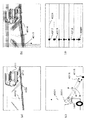
まず、図31を用いて、前記従来例の動作を説明する。図31(a)は実際の撮像手段と仮想視点と路面の位置関係を説明するための概略図である。この図において、車両に取り付けられた撮像手段1001は、車両後方の主に路面を下向きの角度で撮像している。ここで撮像手段1001の画像のある画素の方向1002が3次元的路面の点1003を写していると仮定すると、上空の仮想の視点(仮想カメラ)1004で見た場合の位置は、仮想カメラ1004の画像の画面中の1005の方向の画素に対応することが判る。図31(b)は、実際の駐車場での車両と後方カメラと駐車場の周囲の状況を示したものである。撮像手段1001は、駐車場内の視野範囲1006の画像を撮像する。ここでは特に前記ある画素の方向1002は、路面上の白線のコーナーの点1003を写している。図31(c)は、実際に撮像手段1001から得られる画像である。路面上の白線のコーナーの点1003は、上空の仮想の視点1004で見た方向1005の画素に対応するように位置を変換され合成される。図31(d)は合成された画像である。この図において、点1003は路面上に位置するので、車両からの相対位置関係が正確に再現される。また他の駐車区画の白線もすべて路面上に位置するので、合成画像上で車両からの相対位置関係が正確に再現される。
First, the operation of the conventional example will be described with reference to FIG. FIG. 31A is a schematic diagram for explaining the positional relationship among actual imaging means, a virtual viewpoint, and a road surface. In this figure, an imaging means 1001 attached to the vehicle images mainly the road surface behind the vehicle at a downward angle. Assuming that the
運転者はこの合成画像を見ることによって、車両と周囲の関係を正確に把握することができる。 The driver can accurately grasp the relationship between the vehicle and the surroundings by looking at the composite image.
しかしながら、この従来技術は次のような課題を有している。図32を用いて、その従来例の課題を説明する。 However, this prior art has the following problems. The problem of the conventional example will be described with reference to FIG.
図32(a)は、前述の図31(a)の場合において、路面以外に位置する物体、例えば車のバンパーなどが映る場合について説明するものである。この場合撮像手段1001から方向1002に撮像される点は、3次元的に路面より上に位置する点(車のバンパー)2001となっている。しかしながら、仮想の視点1004から合成する場合は路面を仮定しているので、方向1002を延長して路面に接する点2002上に存在するものとして画像合成が行われる。
FIG. 32A illustrates a case where an object located on a surface other than the road surface, such as a car bumper, is reflected in the case of FIG. 31A described above. In this case, a point imaged in the
図32(b)は、実際の車両と後方カメラと、後方の車両のバンパーの位置の点2001を示したものである。図32(c)は、撮像手段1001の撮像画像である。撮像画像上では、バンパーの位置の点2001と、その方向1002を延長して路面に接する点2002は、当然同一点上に重なって見える。しかしながら、図32(d)に示されている合成画像では、点2002は点2001より遠方に合成される。さらに後方の車両の他の部分も2003に示されているように路面に接触しているタイヤの部分以外は、実際よりも遠方に存在するように合成され、大きく歪んだものとなる。
FIG. 32B shows a
特開昭58-110334号公報 JP 58-110334 A
このように、従来の技術では、視点変換に地面しか仮定していないため、実際に3次元的に地面に位置しないもの、例えば他の車両や障害物が、合成画像上で歪んでしまう。 As described above, in the conventional technique, only the ground is assumed for the viewpoint conversion, and therefore, what is actually not three-dimensionally positioned on the ground, for example, another vehicle or an obstacle, is distorted on the composite image.
さらに、運転支援装置としてこれを利用するとき、他の車のバンパーなどが実際よりも遠くに位置するように表示されてしまうために、この画像を見て十分な距離があると認識して運転すると、実際の障害物には距離が十分ではなく、その結果接触しやすくなる。このため、上述の位置ずれおよび画像の歪みを除去することが実用上の大きな課題である。 In addition, when using this as a driving support device, bumpers of other cars are displayed so that they are located farther than they actually are. Then, the distance is not enough for an actual obstacle, and as a result, it becomes easy to contact. For this reason, it is a big practical problem to remove the above-described positional deviation and image distortion.
このような上方からの視点変換画像の歪みの対策としては、特開平7-186833号公報に開示されている例がある。この例では、画面全体で同一色の抽出を行い、その領域の膨張と収縮により道路面と非道路面領域とを分離し、道路面については上方からの変換画像を合成し、非道路面については、その領域の入力画像を視点変換は行わずに拡大縮小のみを行い、前記変換画像上に貼り付けるという作業を行う。このため、道路より上に位置する障害物も歪むことなく画像の合成ができる。 As a countermeasure against such distortion of the viewpoint-converted image from above, there is an example disclosed in Japanese Patent Laid-Open No. 7-188683. In this example, the same color is extracted on the entire screen, the road surface and the non-road surface region are separated by expansion and contraction of the region, and the converted image from above is synthesized for the road surface, Does not perform viewpoint conversion on the input image in that area, but only enlarges / reduces and pastes it on the converted image. For this reason, it is possible to synthesize an image without distorting an obstacle located above the road.
しかしながら、この例では、以下の(1)〜(3)に記載したような課題が残る。 However, in this example, the problems as described in the following (1) to (3) remain.
(1)色情報により道路、非道路領域の分離を行うため、道路面でテクスチャの大きく変わる部分や、ビルなど道路とよく似た色をした部分などでは、分離が不正確になってしまう。 (1) Since roads and non-road regions are separated based on color information, separation is inaccurate at portions where the texture changes greatly on the road surface, or portions such as buildings that have colors similar to roads.
(2)バンパーなど地面から離れた障害物は、やはり実際よりも遠方まで道路であるように合成される。 (2) An obstacle such as a bumper away from the ground is synthesized so that it is a road farther than it actually is.
(3)道路面は上方の視点からの画像に変換され、障害物は入力画像のままなので、合成画像が不自然であり、運転者が周囲情報を直感的に把握し易いとは限らない。 (3) Since the road surface is converted into an image from an upper viewpoint and the obstacle remains as the input image, the composite image is unnatural, and it is not always easy for the driver to intuitively grasp the surrounding information.
また、この例の(1)の課題について、ステレオ画像を用いて道路面と非道路面を分離する技術が特開平7-334679号公報に開示されている。この例では、左右のカメラからの画像を道路面上に投影した位置で一致するように関連づけ、この2つの画像信号が閾値内で類似する部分を道路領域とし、それ以外を非道路領域として分離するというものである。 Regarding the problem (1) of this example, Japanese Patent Laid-Open No. 7-334679 discloses a technique for separating a road surface and a non-road surface using a stereo image. In this example, the images from the left and right cameras are related so that they match at the position projected on the road surface, and the two image signals that are similar within the threshold are defined as road areas, and the rest are separated as non-road areas. It is to do.
ただしこの例によっても、以下の(1)〜(3)に記載した課題が残る。
(1)バンパーなど地面から離れた障害物は、やはり実際よりも遠方まで道路であるように認識される。
However, even with this example, the problems described in the following (1) to (3) remain.
(1) Obstacles such as bumpers that are far from the ground are recognized as roads farther than they actually are.
(2)左右配置のステレオカメラのため垂直エッジの部分は認識しやすいが、エッジの無い部分や、水平エッジの部分は認識ができない。特にバンパーなど地面から離れた障害物の道路との境界は、画面上水平エッジとなりやすい。 (2) The vertical edge portion is easy to recognize because of the left and right stereo cameras, but the portion without the edge and the horizontal edge portion cannot be recognized. In particular, a boundary with an obstacle road away from the ground such as a bumper tends to be a horizontal edge on the screen.
(3)この例の中では上方からの視点変換については述べられていないが、障害物の変換画像上での歪み補正については効果がない。 (3) Although viewpoint conversion from above is not described in this example, there is no effect on distortion correction on the converted image of the obstacle.
本発明は、このような従来の運転支援装置が有する課題を解決するためになされたもので、その目的は、道路面と非道路面とを分離することで、地面から離れた障害物であっても実際の距離値を算出する運転支援装置および方法、ならびに演算装置を提供することにある。 The present invention has been made in order to solve the problems of such a conventional driving support device, and an object of the present invention is to provide an obstacle away from the ground by separating a road surface and a non- road surface. However, an object is to provide a driving support device and method for calculating an actual distance value , and an arithmetic device .
本発明の一態様に係る運転支援装置は、撮像手段で撮像した画像に基づいて求められる前記撮像手段から障害物までの距離データを用いて運転を支援する運転支援装置であって、前記撮像手段により撮像された路面を含む複数の画像から視差データを算出する算出手段と、前記撮像手段の入力画像から検出した視差と前記視差データとに基づいて、前記路面を含む画像における所定の位置が路面に存在するか路面より上に存在するか判定し、前記路面より上に存在する位置について前記撮像手段からの距離値を求め、前記路面より上に存在する位置に挟まれた領域を抽出する抽出手段と、前記領域を挟む前記路面より上に存在する位置の距離値を線形補間して、前記撮像手段から前記領域までの第1の距離データを算出する設定手段と、を備えることを特徴とする。この構成により、道路面と非道路面とを分離することで、地面から離れた障害物であっても実際の距離値を算出することとなる。 A driving support apparatus according to an aspect of the present invention is a driving support apparatus that supports driving using distance data from the imaging unit to an obstacle obtained based on an image captured by an imaging unit, the imaging unit A predetermined position in the image including the road surface based on the parallax data calculated from the plurality of images including the road surface captured by the imaging unit, the parallax detected from the input image of the imaging unit and the parallax data; Extraction to determine whether or not the vehicle exists above the road surface, obtain a distance value from the imaging means for a position above the road surface, and extract a region sandwiched between positions above the road surface And setting means for calculating first distance data from the imaging means to the area by linearly interpolating a distance value of a position existing above the road surface across the area. Characterized in that that. With this configuration, the road surface and the non- road surface are separated, and an actual distance value is calculated even for an obstacle away from the ground .
また、本発明の一態様に係る運転支援装置は、移動体に設置された撮像手段と、前記撮像手段で撮像された1つ以上の画像を、路面モデルを基に前記撮像手段の位置より上方の仮想視点で見た画像または上方から直交投影した画像に変換する変換手段と、前記撮像手段の撮像画像間の視差が路面モデル上の視差と一致しない領域を障害物領域として検出する障害物領域検出手段とを備えたことを特徴とする。この構成により、撮像手段の撮像画像間の視差と路面モデルの視差とを用いて路面以外の領域を障害物領域として検出することとなる。 The driving support device according to an aspect of the present invention is an image pickup unit installed on a moving body and one or more images picked up by the image pickup unit above the position of the image pickup unit based on a road surface model. An obstacle region for detecting, as an obstacle region, a region where a parallax between images captured by the virtual viewpoint or an image orthogonally projected from above and a parallax between captured images of the imaging unit does not match a parallax on a road surface model And detecting means. With this configuration, a region other than the road surface is detected as an obstacle region using the parallax between the captured images of the imaging unit and the parallax of the road surface model.
さらに、本発明の一態様に係る運転支援装置は、移動体に設置された撮像手段と、前記撮像手段で撮像された1つ以上の画像を、路面モデルを基に前記撮像手段の位置より上方の仮想視点で見た画像または上方から直交投影した画像に変換する変換手段と、前記変換された画像間で一致しない領域を障害物領域として検出する障害物領域検出手段と、前記変換された画像中に前記障害物領域をオーバーレイ合成するオーバーレイ手段と、前記合成された画像を表示する表示手段とを備えたことを特徴とする。この構成により、変換された画像の間で一致しない領域を障害物領域として検出し、その障害物領域を示す信号を前記変換された画像中にオーバーレイ合成し、表示することとなる。 Furthermore, the driving support apparatus according to an aspect of the present invention includes an imaging unit installed on a moving body and one or more images captured by the imaging unit, above the position of the imaging unit based on a road surface model. Conversion means for converting an image viewed from the virtual viewpoint or an image orthogonally projected from above, obstacle area detection means for detecting an area that does not match between the converted images as an obstacle area, and the converted image It is characterized by comprising overlay means for overlaying and synthesizing the obstacle area, and display means for displaying the synthesized image. With this configuration, an area that does not match between the converted images is detected as an obstacle area, and a signal indicating the obstacle area is overlay-synthesized in the converted image and displayed.
そして、本発明の一態様に係る運転支援装置は、移動体に設置された撮像手段と、前記撮像手段で撮像された1つ以上の画像を、路面モデルを基に前記撮像手段からの距離と角度とを座標とした中間画像に変換する中間画像変換手段と、前記変換された画像間で一致しない領域を検出し、さらに前記領域内の2つの画像を比較して、実際の距離を推定し、この推定された距離を用いて前記変換された画像中の前記領域の距離位置を修正し、この修正された領域を障害物領域として出力する障害物領域検出手段と、前記変換された画像に前記障害物領域をオーバーレイ合成するオーバーレイ手段と、前記合成された画像を路面の通常座標画像に変換する変換手段と、前記変換された画像を表示する表示手段とを備えたことを特徴とする。この構成により、撮像手段からの距離と角度とを座標とした中間画像間における一致しない領域の実際の距離を推定して位置を修正し、その修正された領域を障害物領域として検出し、その障害物領域を示す信号を中間画像中に合成し、この合成画像を通常座標画像に変換し、表示することとなる。 The driving support apparatus according to one aspect of the present invention includes an imaging unit installed in a moving body, and one or more images captured by the imaging unit, and a distance from the imaging unit based on a road surface model. An intermediate image converting means for converting into an intermediate image with coordinates as an angle, an area that does not match between the converted images is detected, and two images in the area are compared to estimate an actual distance An obstacle area detecting means for correcting the distance position of the area in the converted image using the estimated distance and outputting the corrected area as an obstacle area; An overlay unit that overlays the obstacle region, a conversion unit that converts the combined image into a normal coordinate image of a road surface, and a display unit that displays the converted image are provided. With this configuration, the actual distance of the non-matching region between the intermediate images with the distance and angle from the imaging means as coordinates is estimated, the position is corrected, the corrected region is detected as an obstacle region, A signal indicating the obstacle area is synthesized in the intermediate image, and the synthesized image is converted into a normal coordinate image and displayed.
また、本発明の一態様に係る運転支援装置は、移動体に設置された撮像手段と、前記撮像手段で撮像された画像を、路面モデルを基に前記撮像手段の位置より上方の仮想視点で見た画像または上方から直交投影した画像に変換する変換手段と、前記変換された画像を表示する表示手段とを備えた運転支援装置であって、前記変換手段において、前記撮像手段の画面の各画素の路面モデル上の面積および路面への角度を基に強度を求め、この強度を基に画素の明るさおよび色づけに変化を持たせることを特徴とする。この構成により、撮像手段の画面の各画素の路面モデル上の面積および路面への角度を基に画素の明るさおよび色づけを変化させることとなる。 The driving support device according to an aspect of the present invention is an image capturing unit installed on a moving body and an image captured by the image capturing unit, based on a road surface model, at a virtual viewpoint above the position of the image capturing unit. A driving support apparatus comprising: a conversion unit that converts a viewed image or an image that is orthogonally projected from above; and a display unit that displays the converted image. In the conversion unit, each of the screens of the imaging unit The intensity is obtained based on the area of the pixel on the road surface model and the angle to the road surface, and the brightness and coloring of the pixel are changed based on the intensity. With this configuration, the brightness and coloring of the pixels are changed based on the area on the road surface model of each pixel on the screen of the imaging unit and the angle to the road surface.
さらに、本発明の一態様に係る運転支援装置は、移動体に設置された撮像手段と、前記撮像手段で撮像された1つ以上の画像を、路面モデルおよび円筒モデルを基に前記撮像手段からの距離または高さおよび角度を座標とした中間画像に変換する中間画像変換手段と、前記変換された画像間で一致しない領域を検出し、さらに前記領域内の2つの画像を比較して、実際の距離を推定し、この推定された距離を用いて前記変換された画像中の前記領域の距離位置を修正し、この修正された領域を障害物領域として出力する障害物領域検出手段と、前記変換された画像に前記障害物領域をオーバーレイ合成するオーバーレイ手段と、前記合成された画像を路面の通常座標画像に変換する変換手段と、前記変換された画像を表示する表示手段とを備えたことを特徴とする。この構成により、撮像手段からの距離または高さおよび角度を座標とした中間画像における一致しない領域の実際の距離を推定して位置を修正し、その修正された領域を障害物領域として検出し、その障害物領域を示す信号を中間画像中に合成し、この合成画像を通常座標画像に変換し、表示することとなる。 Furthermore, the driving support apparatus according to an aspect of the present invention provides an imaging unit installed on a moving body and one or more images captured by the imaging unit from the imaging unit based on a road surface model and a cylindrical model. An intermediate image conversion means for converting into an intermediate image with coordinates of the distance or height and angle of the image, an area that does not match between the converted images is detected, and two images in the area are compared, Obstacle region detecting means for correcting the distance position of the region in the transformed image using the estimated distance and outputting the corrected region as an obstacle region; Overlay means for overlaying the obstacle area on the converted image, conversion means for converting the synthesized image into a normal coordinate image of a road surface, and display means for displaying the converted image Characterized in that was. With this configuration, the position or position is corrected by estimating the actual distance of the non-matching area in the intermediate image with the distance or height and angle from the imaging means as coordinates, and the corrected area is detected as an obstacle area. A signal indicating the obstacle region is synthesized in the intermediate image, and the synthesized image is converted into a normal coordinate image and displayed.
そして、本発明の一態様に係る運転支援方法は、撮像手段で撮像した画像に基づいて求められる前記撮像手段から障害物までの距離データを用いて運転を支援する運転支援方法であって、算出手段は、前記撮像手段により撮像された路面を含む複数の画像から視差データを算出し、抽出手段は、前記撮像手段の入力画像から検出した視差と前記視差データとに基づいて、前記路面を含む画像における所定の位置が路面に存在するか路面より上に存在するか判定し、前記路面より上に存在する位置について前記撮像手段からの距離値を求め、前記路面より上に存在する位置に挟まれた領域を抽出し、設定手段は、前記領域を挟む前記路面より上に存在する位置の距離値を線形補間して、前記撮像手段から前記領域までの距離データを算出することを特徴とする。この構成により、道路面と非道路面とを分離して地面から離れた障害物であっても実際の距離値を算出することとなる。 A driving support method according to an aspect of the present invention is a driving support method that supports driving using distance data from the imaging unit to an obstacle that is obtained based on an image captured by the imaging unit. The means calculates parallax data from a plurality of images including the road surface imaged by the imaging means, and the extracting means includes the road surface based on the parallax detected from the input image of the imaging means and the parallax data. It is determined whether a predetermined position in the image exists on the road surface or above the road surface, and a distance value from the imaging means is obtained for the position existing above the road surface, and is sandwiched between the positions existing above the road surface. extracting a region, setting means, this to the distance value of the position that is present above the road surface sandwiching the region by linear interpolation, and calculates the distance data from the imaging means to said region The features. With this configuration, an actual distance value is calculated even for an obstacle separated from the ground by separating the road surface and the non- road surface .
また、本発明の一態様に係る演算装置は、撮像手段で撮像した画像に基づいて求められる前記撮像手段から障害物までの距離データを演算する演算装置であって、前記撮像手段により撮像された路面を含む複数の画像から視差データを算出する算出手段と、前記撮像手段の入力画像から検出した視差と前記視差データとに基づいて、前記路面を含む画像における所定の位置が路面に存在するか路面より上に存在するか判定し、前記路面より上に存在する位置について前記撮像手段からの距離値を求め、前記路面より上に存在する位置に挟まれた領域を抽出する抽出手段と、前記領域を挟む前記路面より上に存在する位置の距離値を線形補間して、前記撮像手段から前記領域までの距離データを算出する設定手段と、を備えることを特徴とする。この構成により、道路面と非道路面とを分離することで、地面から離れた障害物であっても実際の距離値を算出することとなる。 An arithmetic device according to one aspect of the present invention is a arithmetic device that calculates distance data from the imaging unit to an obstacle that is obtained based on an image captured by the imaging unit, and is captured by the imaging unit. Whether a predetermined position in the image including the road surface exists on the road surface based on the calculation unit that calculates the parallax data from a plurality of images including the road surface, and the parallax detected from the input image of the imaging unit and the parallax data Determining whether there is above the road surface, obtaining a distance value from the imaging means for a position above the road surface, and extracting means for extracting a region sandwiched between positions above the road surface; and the distance value of the position that is present above the road surface sandwiching the region by linear interpolation, characterized in that it comprises a setting means for calculating distance data to the region from the image pickup means With this configuration, the road surface and the non- road surface are separated, and an actual distance value is calculated even for an obstacle away from the ground .
以上説明したように、本発明は、撮像手段により撮像された路面を含む複数の画像から視差データを算出し、撮像手段の入力画像から検出した視差と視差データとに基づいて、路面を含む画像における所定の位置が路面に存在するか路面より上に存在するか判定し、路面より上に存在する位置について撮像手段からの距離値を求め、路面より上に存在する位置に挟まれた領域を抽出し、領域を挟む路面より上に存在する位置の距離値を線形補間して、撮像手段から領域までの距離データを算出することにより、道路面と非道路面とを分離して地面から離れた障害物であっても実際の距離値を算出することができるという優れた効果を有する運転支援装置を提供することができるものである。 As described above, the present invention calculates parallax data from a plurality of images including a road surface imaged by an imaging unit, and includes an image including a road surface based on the parallax and parallax data detected from an input image of the imaging unit. It is determined whether the predetermined position on the road surface is above the road surface, the distance value from the imaging means is obtained for the position above the road surface, and the region sandwiched between the positions above the road surface is determined By extracting and linearly interpolating the distance value of the position existing above the road surface across the area and calculating the distance data from the imaging means to the area , the road surface and the non- road surface are separated and separated from the ground Therefore, it is possible to provide a driving support device having an excellent effect that an actual distance value can be calculated even with an obstacle .
また、本発明は、撮像手段で撮像された画像を上方の仮想視点で見た画像または上方から直交投影した画像に変換し、かつ複数の撮像画像間の視差と路面モデルの視差とを用いて路面以外の領域を障害物領域として検出し、その障害物領域を示す信号を前記変換画像信号に合成し、表示することにより、障害物までの距離と方向をより判り易く正確に提示することができるという優れた効果を有する運転支援装置を提供することができるものである。 Further, the present invention converts an image captured by the imaging unit into an image viewed from an upper virtual viewpoint or an orthogonally projected image from above, and uses parallax between a plurality of captured images and parallax of a road surface model. An area other than the road surface is detected as an obstacle area, and a signal indicating the obstacle area is combined with the converted image signal and displayed, so that the distance and direction to the obstacle can be presented more easily and accurately. It is possible to provide a driving support device having an excellent effect of being able to.
さらに、本発明は、撮像手段で撮像された画像を上方の仮想視点で見た画像または上方から直交投影した画像に変換し、かつ変換された画像の間で一致しない領域を障害物領域として検出し、その障害物領域を示す信号を前記変換画像信号に合成し、表示することにより、障害物までの距離と方向をより判り易く正確に提示することができるという優れた効果を有する運転支援装置を提供することができるものである。 Furthermore, the present invention converts an image captured by the imaging means into an image viewed from the upper virtual viewpoint or an orthogonally projected image from above, and detects a region that does not match between the converted images as an obstacle region. Then, by combining the signal indicating the obstacle region with the converted image signal and displaying it, the driving support device having an excellent effect that the distance and direction to the obstacle can be presented more easily and accurately. Can be provided.
そして、本発明の運転支援装置は、撮像手段で撮像された画像を前記撮像画像を撮像手段からの距離と角度とを座標とした中間画像に変換し、その中間画像間における一致しない領域の実際の距離を推定して位置を修正し、その修正された領域を障害物領域として検出し、その障害物領域を示す信号を中間画像中に合成し、この合成画像を通常座標画像に変換し、表示することにより、障害物までの距離と方向をより判り易く正確に提示することができるという優れた効果を有する運転支援装置を提供することができるものである。 Then, the driving support device of the present invention converts the image captured by the imaging unit into an intermediate image using the captured image as a coordinate with a distance and an angle from the imaging unit, and the actual region of the mismatch between the intermediate images is actually converted. The position is corrected by estimating the distance of the detected area, the corrected area is detected as an obstacle area, a signal indicating the obstacle area is synthesized in the intermediate image, and the synthesized image is converted into a normal coordinate image. By displaying it, it is possible to provide a driving support device having an excellent effect that the distance and direction to the obstacle can be presented more easily and accurately.
また、本発明は、撮像画像を上方の仮想視点で見た画像または上方から直交投影した画像に変換し、かつ変換画像上で距離や歪みの大きい障害物の領域を判り易く提示することにより、画像中の信頼性の高い部分と低い部分とを提示することができるという優れた効果を有する運転支援装置を提供することができるものである。 Further, the present invention converts the captured image into an image viewed from the upper virtual viewpoint or an image orthogonally projected from above, and presents an area of an obstacle with a large distance or distortion on the converted image in an easily understandable manner. It is possible to provide a driving assistance device having an excellent effect of being able to present a highly reliable part and a low part in an image.
さらに、本発明は、撮像手段で撮像された画像を前記撮像画像を撮像手段からの距離または高さおよび角度を座標とした中間画像に変換し、その中間画像間における一致しない領域の実際の距離を推定して位置を修正し、その修正された領域を障害物領域として検出し、その障害物領域を示す信号を中間画像中に合成し、この合成画像を通常座標画像に変換し、表示することにより、障害物までの距離と方向をより判り易く正確に提示することができるという優れた効果を有する運転支援装置を提供することができるものである。 Furthermore, the present invention converts the image captured by the imaging unit into an intermediate image with the captured image as a coordinate or distance and height and angle from the imaging unit, and the actual distance of the non-matching region between the intermediate images , The position is corrected, the corrected area is detected as an obstacle area, a signal indicating the obstacle area is synthesized in the intermediate image, and the synthesized image is converted into a normal coordinate image and displayed. Thus, it is possible to provide a driving assistance device having an excellent effect that the distance and direction to the obstacle can be presented more easily and accurately.
そして、本発明は、撮像手段で撮像された画像を前記撮像手段間を結ぶ直線を軸とした軸対称な面を投影面とした中間画像に変換し、その中間画像間における一致しない領域の実際の距離を推定して位置を修正し、その修正された領域を障害物領域として検出し、その障害物領域を示す信号を中間画像中に合成し、この合成画像を通常座標画像に変換し、表示することにより、障害物までの距離と方向をより判り易く正確に提示することができるという優れた効果を有する運転支援装置を提供することができるものである。 Then, the present invention converts an image captured by the image capturing means into an intermediate image having an axially symmetric surface about the straight line connecting the image capturing means as a projection plane, and actuality of non-coincident areas between the intermediate images. The position is corrected by estimating the distance of the detected area, the corrected area is detected as an obstacle area, a signal indicating the obstacle area is synthesized in the intermediate image, and the synthesized image is converted into a normal coordinate image. By displaying it, it is possible to provide a driving support device having an excellent effect that the distance and direction to the obstacle can be presented more easily and accurately.
また、本発明は、所定の視差を有する複数の画像を撮像し、複数の撮像画像の視差に基づいて視点変換画像を補正し、表示することにより、障害物までの距離と方向をより判り易く正確に提示することができるという優れた効果を有する運転支援装置を提供することができるものである。 In addition, the present invention captures a plurality of images having a predetermined parallax, corrects the viewpoint conversion image based on the parallax of the plurality of captured images, and displays it, thereby making it easier to understand the distance and direction to the obstacle. It is possible to provide a driving support device having an excellent effect of being able to present accurately.
以上述べたように、本発明は、運転者の負担を軽減し、正確で安全な運転を促すことができるという優れた効果を有する運転支援装置を提供することができるものである。 As described above, the present invention can provide a driving support device that has an excellent effect of reducing the burden on the driver and promoting accurate and safe driving.
以下、本発明の実施の形態について、図面を用いて説明する。 Hereinafter, embodiments of the present invention will be described with reference to the drawings.
(第1の実施の形態)
本発明の第1の実施の形態の運転支援装置は、移動体に設置された撮像手段で撮像された画像を上方の仮想視点からの画像に変換し、かつ複数の撮像手段で撮像された画像間の視差を基に路面以外の3次元情報を検出し、その3次元情報を基に前記変換された画像の歪みを補正し、その補正された画像を表示することにより、運転者が車両周囲の障害物の位置関係と周囲状況を直感的かつ正確に確認できるようにしたものである。
(First embodiment)
The driving support apparatus according to the first embodiment of the present invention converts an image captured by an imaging unit installed in a moving body into an image from an upper virtual viewpoint, and images captured by a plurality of imaging units. By detecting three-dimensional information other than the road surface based on the parallax between them, correcting the distortion of the converted image based on the three-dimensional information, and displaying the corrected image, the driver can It is designed to intuitively and accurately confirm the positional relationship and surrounding conditions of obstacles.
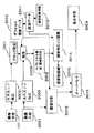
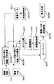
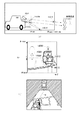
図1は、本発明の第1の実施の形態の運転支援装置のブロック図であり、図2〜図6は、その運転支援装置の動作を説明するための概略図である。 FIG. 1 is a block diagram of the driving support apparatus according to the first embodiment of the present invention, and FIGS. 2 to 6 are schematic diagrams for explaining the operation of the driving support apparatus.
図1に示されているように、本発明の第1の実施の形態の運転支援装置は、2つの撮像手段1001、3001と、それぞれ撮像手段1001、3001で撮像された画像の水平エッジを抽出する水平エッジ抽出手段3002、3003と、水平エッジ抽出手段3002の出力を用いて視差探索のためのブロックの設定を行うブロック設定手段3004と、水平エッジ抽出手段3003の出力と、ブロック設定手段3004の出力と、後述するデフォルト視差データ3010とを基にブロックの探索を行う探索手段3005と、探索手段3005の出力から、各ブロックについてサブピクセル精度の視差と信頼性判定結果を出力するサブピクセル推定・信頼性判定手段3006と、サブピクセル推定・信頼性判定手段3006の出力と、デフォルト視差データ3010と、後述する路面データ3011とを基に撮像手段3001からの画像画面上に3Dマップを作成する3Dマップ作成手段3007と、撮像手段3001からの画像とその画面上の3Dマップとを基に、上方の仮想視点からの画像を合成する3D画像合成手段3008と、3D画像合成手段3008の出力を表示する表示手段3009とを具備する。
As shown in FIG. 1, the driving support apparatus according to the first embodiment of the present invention extracts two imaging means 1001 and 3001, and horizontal edges of images taken by the imaging means 1001 and 3001, respectively. Horizontal edge extraction means 3002, 3003, block setting means 3004 for setting a block for parallax search using the output of the horizontal edge extraction means 3002, output of the horizontal edge extraction means 3003, and block setting means 3004 The search means 3005 for searching for a block based on the output and
また、本発明の第1の実施の形態の運転支援装置は、デフォルト視差データ手段3010と、路面データ手段3011と、車両姿勢情報手段3012とを具備する。 The driving support apparatus according to the first embodiment of the present invention includes default parallax data means 3010, road surface data means 3011, and vehicle attitude information means 3012.
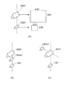
2つの撮像手段1001と撮像手段3001は、図2(a)に示されているような位置に設置されている。ここでは地面に垂直な方向の直線4001上に10cmの間隔をあけた位置に設置され、それぞれの地面からの高さは、100cmと110cmである。それぞれの視線方向4003は、水平から地面に向かって40度の角度で下向きである。2つの撮像手段の視線は平行である。また2つの撮像手段の視野範囲4002は、垂直方向(仰角方向)に90度である。
The two image pickup means 1001 and the image pickup means 3001 are installed at positions as shown in FIG. Here, they are installed on the
図1に示されているこの2つの撮像手段1001、3001からの入力画像としては、それぞれ図2(b)、図2(c)に示されているように、水平方向は殆ど同一で垂直方向に位置が変化した画像が得られる。撮像手段3001は撮像手段1001よりも高い位置に配置されているため、撮像手段3001からの入力画像では、無限遠方の水平線4004の画面上の位置は同じだが、より近くに位置する点(例えば、路面上に位置する白線のある点4005や、車のバンパー上のある点4006)は画面上、図2(b)の画像より下に位置する。そして、この垂直方向の位置の変化は、2つの画像を重ねた図2(d)に示されているように、垂直方向の視差4007や4008となる。ここで4007は路面上に位置する白線の視差であり、4008は路面より上に位置する車のバンパーの視差である。
As shown in FIGS. 2 (b) and 2 (c), the input images from the two imaging means 1001 and 3001 shown in FIG. 1 are almost the same in the horizontal direction and the vertical direction. An image whose position has been changed is obtained. Since the image pickup means 3001 is arranged at a position higher than the image pickup means 1001, the input image from the image pickup means 3001 has the same position on the screen of the
図1に示されている水平エッジ抽出手段3002、3003では、この2つの撮像画像について下記の式[1]に示されている操作で水平エッジの抽出を行う。ここで、Lは画像の輝度信号、x,yは水平、垂直の画素位置である。 In the horizontal edge extraction means 3002 and 3003 shown in FIG. 1, the horizontal edges are extracted from the two captured images by the operation shown in the following equation [1]. Here, L is an image luminance signal, and x and y are horizontal and vertical pixel positions.
L'(x,y)=2*L(x,y)-L(x,y-1)-L(x,y+1) …式[1] L ′ (x, y) = 2 * L (x, y) −L (x, y−1) −L (x, y + 1) (1)
この操作により、例えば、図2(b)の画像は図3(a)のように、画面上水平方向に近いバンパーや白線のエッジ(4009,4010)が強調され、また画面上垂直方向に近いエッジ(4011,4012)は弱められる。 By this operation, for example, as shown in FIG. 3A, the image of FIG. 2B emphasizes the bumper and white line edges (4009, 4010) close to the horizontal direction on the screen and is close to the vertical direction on the screen. The edges (4011, 4012) are weakened.
図1のブロック設定手段3004では、水平エッジ強調手段3002、3003で水平エッジが強調された画像について、視差探索のためのブロックの設定が行われる。図3(b)はそのブロック設定を説明するためのもので、垂直方向に2画素おきの走査線4013にしたがって、式[1]に示したL'(x,y)の極大点と極小点を求め、その点を中心とした縦横5×5画素のブロック4014を設定する。図3(b)に示されているように、このブロックは画面の水平エッジ上に重なりを持って複数配置される。
In the
次に、図1の路面データ3011に基づいたデフォルト視差データ3010について説明する。これは図3(c)に示されているように、2つの撮像手段1001、3001が共に路面を写していると仮定したときに生じる視差を予め計算したものである。図3(c)中、路面上の点4015の視差は角度で4016と計算される。図3(d)は画面上での、このデフォルト視差データを示すものである。無限遠方の水平線4004の位置のデフォルト視差4017は0であるが、それから近づく(画面上、下に下がる)に従って、4018、4019とデフォルト視差は大きくなる。それからさらに下がると、今度は撮像手段1001、3001の視線方向が垂直方向に近くなるので、4020に示されているようにデフォルト視差は小さくなる。
Next, the
路面より上に位置する物体は、このデフォルト視差より大きな視差を生じるので、図1の探索手段3005では、このデフォルト視差を探索の初期値としてさらに大きい視差の方向に探索を行う。 Since an object located above the road surface has a parallax larger than the default parallax, the search means 3005 in FIG. 1 searches in the direction of the larger parallax using the default parallax as an initial value of the search.
探索視差の上限は次のようにして決定する。図4(a)に示されているように、車両からの距離が50cmでかつ地面から垂直な壁4021と、撮像手段1001、3001の真下から60度の角度を持つ壁4022とを仮定したときの視差を概算する。このときの視差4023の画面中の値を探索視差の上限とする。
The upper limit of the search parallax is determined as follows. As shown in FIG. 4A, assuming a
探索手段3005は、前記探索の初期値から上限までの間で、ブロック設定手段3004で設定された5×5画素の信号L'(x+j,y+i)について、撮像手段3001からの画像信号L3'に対して下記の式[2]に示されている相関値Fが最大となる視差DYを探索する。 The search means 3005 uses the image from the imaging means 3001 for the signal L ′ (x + j, y + i) of 5 × 5 pixels set by the block setting means 3004 between the initial value and the upper limit of the search. The signal L3 ′ is searched for the parallax DY that maximizes the correlation value F shown in the following equation [2].
F=ΣiΣjL'(x+j,y+i)*L3'(x+j,y+i+DY) …式[2]
:(i=-2〜2,j=-2〜2)
F = ΣiΣjL ′ (x + j, y + i) * L3 ′ (x + j, y + i + DY) Equation [2]
: (i = -2 ~ 2, j = -2 ~ 2)
サブピクセル推定・信頼性判定手段3006では、さらに前記探索手段3005で求められた視差DYと相関値について解析する。 The subpixel estimation / reliability determination means 3006 further analyzes the parallax DY and the correlation value obtained by the search means 3005.
まず、相関値Fと、ブロック信号L'(x+j,y+i)の自己相関値SS=ΣiΣjL'(x+j,y+i)*L'(x+j,y+i) …式[3]
:(i=-2〜2,j=-2〜2)の比F/Sが閾値が0.75以上のときは信頼性ありと判定し、0.75未満のときは信頼性なしと判定する。
First, the correlation value F and the autocorrelation value SS of the block signal L ′ (x + j, y + i) = ΣiΣjL ′ (x + j, y + i) * L ′ (x + j, y + i). Formula [3]
: When the ratio F / S of (i = -2 to 2, j = -2 to 2) is greater than or equal to 0.75, it is judged as reliable, and when it is less than 0.75, it is judged as unreliable To do.
信頼性ありと判定されたブロックについては、図4(b)に示されているように、1画素単位の視差DYの周囲の相関値Fを用いて2次式で補間した曲線4024の最大点4025を求め、この位置をサブピクセル精度の視差DY’とする。
For the block determined to be reliable, as shown in FIG. 4B, the maximum point of the
サブピクセル推定・信頼性判定手段3006では、各ブロックについてこのサブピクセル精度の視差DY’と信頼性判定結果を出力する。 The subpixel estimation / reliability determination means 3006 outputs the subpixel precision parallax DY 'and the reliability determination result for each block.
3Dマップ作成手段3007では、サブピクセル推定・信頼性判定手段3006の出力である各ブロックについてのサブピクセル精度の視差DY’および信頼性判定結果と、路面データ3001と、デフォルト視差データ3010とを基に撮像手段3001からの画像画面上に3Dマップを作成する。
The 3D map creation means 3007 is based on the subpixel accuracy parallax DY ′ and reliability judgment results,
まず、図4(c)に示されているように、信頼性ありと判定された各ブロックを検出した視差DY'で動かした位置4026には、撮像手段3001からの画像の水平エッジが存在する。またこのとき、図4(d)に示されているように、検出視差DY’がデフォルト視差データ3010に一致する水平エッジ4027は路面上に存在すると判定され、一致しない水平エッジ4028は路面より上に存在すると判定される。路面より上に存在すると判定されたエッジは、検出視差DY’の値によって撮像手段3001からの距離が求められる。
First, as shown in FIG. 4C, a horizontal edge of an image from the
この判定と距離とを基に、図5(a)に示されているように画面全体について3Dマップが作成される。まず走査線4032に示されているように、画面を下方から垂直に走査し、領域4029のように水平エッジを有しないか、有していても路面上に存在すると判定されたエッジしかない場合、その領域は路面に存在すると判定され、路面データ3011の値を基に3D距離が与えられる。一方、路面より上に存在すると判定されたエッジに挟まれた領域4030では、その2つのエッジの距離を線形補間した値が与えられる。路面より上に存在すると判定されたエッジより上の領域4031ではそのエッジの距離のデータが与えられる。
Based on this determination and the distance, a 3D map is created for the entire screen as shown in FIG. First, as shown in the
3D画像合成手段3008は、撮像手段3001からの画像とその画面上の3Dマップとを基に、上方の仮想視点からの画像を合成する。したがって図5(b)に示されているように、バンパーなどの路面より上に存在する点4033でも、路面上の位置4034ではなく正確な3D位置をもとに仮想視点で見た画面上の位置が決定できるので、図5(c)に示されているように、路面上の位置4034ではなく正確な位置4033に画像が合成される。一方、車両の陰などになった部分は、領域4035に示されているように斜線で表示される。
The 3D
また、このとき図5(d)の領域4036に示されているように、路面より上に存在する領域を半透明の赤い幕や点滅等で強調することも可能である。
At this time, as shown in a
表示手段3009には、この合成画像が表示され、運転者は車両周囲の障害物の位置を直感的かつ正確に把握することができる。 The composite image is displayed on the display means 3009, and the driver can intuitively and accurately grasp the position of the obstacle around the vehicle.
なお、図1に示されている車両姿勢情報手段3012は、車両に荷物を積んだ場合や、車両の加速等に伴う姿勢の変化情報を出力する。路面データ手段3011は、この情報に対応して図6に示されているように、撮像手段1001、3001に対する平時の路面位置データ4037に対し、変化した路面位置データ4038を計算する。この変化した路面位置データは、それ以降のデフォルト視差データ手段3010や3Dマップ作成手段3007の処理に反映される。このことによって、車両に荷物を積んだ場合や、車両の加速等に伴って姿勢が変化場合でも正確な画像が合成され、運転者は、この画像を見ることで、常に車両周囲の障害物の位置を直感的かつ正確に把握することができる。
Note that the vehicle posture information means 3012 shown in FIG. 1 outputs posture change information when a load is loaded on the vehicle or when the vehicle is accelerated. Corresponding to this information, the road surface data means 3011 calculates changed road
ここで、第1の実施の形態では、2つの撮像手段1001、3001を垂直方向に10cmの間隔をあけて設置することにより、その視差によって障害物の合成画像上の歪みを補正することができたが、このとき、視差に微量の誤差が含まれていても、2つの撮像手段の間隔が垂直方向なので、障害物までの距離には誤差の影響が生じても、その障害物の方向には影響は殆ど表れないという利点がある。これは車両を運転する上で大変重要な利点である。
Here, in the first embodiment, by disposing the two
また、この2つの撮像手段1001、3001を垂直方向に間隔をあけて配置することで、その後の視差検出処理を水平エッジ抽出手段で検出されたエッジ部分に限定することができ、その処理量を大幅に削減できる。車両のバンパーなど、路面から浮いている部分は殆ど画面上で水平エッジを持っているので、その限定された処理でも障害物を漏らすことなく検出できるという利点がある。 In addition, by disposing the two image pickup means 1001 and 3001 at intervals in the vertical direction, the subsequent parallax detection processing can be limited to the edge portion detected by the horizontal edge extraction means, and the amount of processing can be reduced. It can be greatly reduced. Since a portion floating from the road surface such as a bumper of a vehicle has a horizontal edge on the screen, there is an advantage that it can be detected without leaking an obstacle even in the limited processing.
このように、本発明の第1の実施の形態によれば、移動体に設置された撮像手段で撮像された画像を上方の仮想視点からの画像に変換し、かつ複数の撮像手段で撮像された画像間の視差を基に路面以外の3次元情報を検出し、その3次元情報を基に前記変換された画像の歪みを補正し、その補正された画像を表示することにより、障害物までの距離と方向をより判り易く、かつ正確に提示する。したがって、運転者は、表示された画像を見ることで、車両周囲の障害物の位置関係と周囲状況を直感的かつ正確に確認することができる。 As described above, according to the first embodiment of the present invention, the image captured by the imaging unit installed on the moving body is converted into an image from the upper virtual viewpoint, and is captured by the plurality of imaging units. By detecting three-dimensional information other than the road surface based on the parallax between the images, correcting the distortion of the converted image based on the three-dimensional information, and displaying the corrected image, the obstacle can be displayed. The distance and direction of the are presented in an easy-to-understand and accurate manner. Therefore, the driver can intuitively and accurately confirm the positional relationship and surrounding conditions of obstacles around the vehicle by looking at the displayed image.
(第2の実施の形態)
本発明の第2の実施の形態の運転支援装置は、移動体に設置された撮像手段で撮像された画像を上方から直交投影した画像に変換し、かつ複数の撮像手段で撮像された画像間の視差と路面モデルの視差とを用いて路面以外の領域を障害物領域として検出し、その障害物領域を示す信号を前記変換画像信号に合成し、表示することにより、運転者が車両周囲の障害物の位置関係と周囲状況を直感的かつ正確に確認することができるようにしたものである。
(Second Embodiment)
The driving support apparatus according to the second embodiment of the present invention converts an image captured by an imaging unit installed on a moving body into an image obtained by orthogonal projection from above, and between images captured by a plurality of imaging units. The area other than the road surface is detected as an obstacle area using the parallax of the road surface model and the parallax of the road surface model, and a signal indicating the obstacle area is synthesized and displayed on the converted image signal so that the driver can It is designed to intuitively and accurately confirm the positional relationship of obstacles and the surrounding situation.
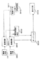
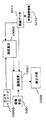
図7は、本発明の第2の実施の形態の運転支援装置のブロック図であり、図8〜図11はその動作を説明するための概略図である。また、図12は、本発明の第2の実施の形態の運転支援装置の変形例のブロック図である。図7と図12のブロック図中、図1と同じ符号が付されたブロック要素は図1のブロック要素と同じ構成および機能を有する。 FIG. 7 is a block diagram of the driving support apparatus according to the second embodiment of the present invention, and FIGS. 8 to 11 are schematic diagrams for explaining the operation thereof. FIG. 12 is a block diagram of a modification of the driving support apparatus according to the second embodiment of the present invention. In the block diagrams of FIGS. 7 and 12, the block elements denoted by the same reference numerals as those in FIG. 1 have the same configuration and function as the block elements in FIG.
本発明の第2の実施の形態の運転支援装置は、画像投影手段3013、障害物エッジ距離手段3014、障害物領域手段3015、およびオーバーレイ手段3016を備えており、3Dマップ作成手段および3D画像合成手段を備えていない点において第1の実施の形態の運転支援装置と異なる。
The driving support apparatus according to the second embodiment of the present invention includes an
まず路面投影手段3013は、図1の3D画像合成手段3008とは異なり、路面データ手段3011のデータを基に、撮像手段3001からの入力画像を図8(a)に示されているように、路面に投影した位置に存在するように合成する。このとき視点は第1の実施の形態のような仮想の視点ではなく、図8(a)の視点6001に示されているように、真上からの直交投影で得られる画像を合成する。このとき得られる合成画像は、図8(b)に示されているように、従来例と同様、路面より上に位置する車両のバンパーの点6002などが、より遠くの点6003に存在するような歪んだ画像となる。
First, the road
障害物エッジ距離手段3014は、第1の実施の形態の3Dマップ作成手段3007と同様に、図8(c)に示されている2つの画像の水平エッジについて、サブピクセル推定・信頼性判定手段3006から得られるその視差から、路面より上に存在するエッジを障害物エッジとして検出し、撮像手段3001からの距離を算出する。図8(c)の走査線6006に示されているように、画面を下方から垂直方向に走査し、その垂直ラインについて、障害物ラインが存在した場合、その距離の最小値が、その垂直ライン毎に記憶され、出力される。
The obstacle edge distance means 3014 is a sub-pixel estimation / reliability determination means for the horizontal edges of the two images shown in FIG. 8C, similarly to the 3D map creation means 3007 of the first embodiment. From the parallax obtained from 3006, an edge present above the road surface is detected as an obstacle edge, and the distance from the imaging means 3001 is calculated. As shown in the
障害物領域手段3015は、図8(d)に示されているように、障害物エッジ距離手段3014の出力の、垂直ライン毎の障害物ラインの距離の最小値を路面に投影した位置6008と、それ以遠の領域6009とを障害物領域として合成する。
As shown in FIG. 8 (d), the obstacle area means 3015 includes a
オーバーレイ手段3016は、合成画像と別の層(レイヤー)に運転者への指示を書き込み、図9(a)に示されているように、図8(b)、図8(d)の合成画像を重ね合わせて合成する。このとき障害物領域6009は、画像上半透明の赤い膜として図8(b) の車両の存在する領域に合成される。
The overlay means 3016 writes an instruction to the driver on a layer (layer) different from the composite image, and as shown in FIG. 9A, the composite image of FIG. 8B and FIG. Are combined. At this time, the
表示手段3009には、このオーバーレイ手段3016の出力が表示される。運転者は、この合成画像を見ることで、路面上の白線の位置を正確に把握することができ、また他の車両などの障害物までの自車両からの距離と方向を正確に把握することができるので、従来例と比較しても大幅に安全かつ正確に車両を運転することができる。 The display means 3009 displays the output of the overlay means 3016. By looking at this composite image, the driver can accurately grasp the position of the white line on the road surface, and accurately grasp the distance and direction from the own vehicle to other obstacles such as vehicles. Therefore, the vehicle can be driven much more safely and accurately than the conventional example.
この第2の実施の形態では、第1の実施の形態に比較して、撮像手段3001からの入力画像をリアルタイムに変化する3Dマップに合わせて合成しなくても良く、予め定められた路面モデルへの投影変換だけで良いので、実回路での実現が容易であるという利点がある。
In the second embodiment, as compared with the first embodiment, the input image from the
また障害物エッジ距離手段3014、障害物領域手段3015の動作も、3Dマップ作成手段3007に比較して、垂直ライン毎の障害物ラインの距離の最小値だけを解析するので、その処理が比較的簡単であるという利点がある。 Also, the operation of the obstacle edge distance means 3014 and the obstacle area means 3015 is only compared with the 3D map creation means 3007 because it analyzes only the minimum value of the obstacle line distance for each vertical line. There is an advantage of being simple.
これらのことより、第2の実施の形態では、第1の実施の形態に比較して、実回路での実現が大幅に容易であるという利点があり、かつ第1の実施の形態と同様に、運転者が表示画像を見ることで、路面上の白線を正確に把握することができ、また他の車両などの障害物までの自車両からの距離と方向を正確に把握することができるので、従来例と比較しても大幅に安全かつ正確に車両を運転することができるという効果が得られる。 Therefore, the second embodiment has an advantage that it is much easier to implement with an actual circuit than the first embodiment, and is the same as the first embodiment. By seeing the display image, the driver can accurately grasp the white line on the road surface, and can accurately grasp the distance and direction from the own vehicle to obstacles such as other vehicles. As compared with the conventional example, the effect that the vehicle can be driven significantly safely and accurately is obtained.
なお、図9(b)に示されているように、障害物領域6009ではなく、障害物ラインの距離の最小値を路面に投影した位置6008だけを境界線として表示しても良い。この場合でも、運転者は障害物までの距離と方向を正確に把握することができるので、安全かつ正確に車両を運転することができるという効果が得られる。
As shown in FIG. 9B, not the
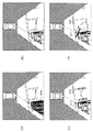
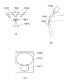
図10(a)〜(c)は、実際の撮像画像での図9(b)の効果を示す例である。図10(a)は、駐車操作中の車の後方カメラから撮像される画像である。ここでは、広角な範囲を撮像するために魚眼レンズを用いている。画像には、これから駐車しようとするスペースと、その左側にトラック、右側に乗用車が映っている。図10(b)は図10(a)の撮像画像を用いて従来例によって合成された画像である。合成画像の中央から右にかけて、上方から見た駐車場の状況と、左に自車両を示すCGが合成されている。ここでは、路面にある白線は正確な位置に合成されるので、運転者は自車両と駐車スペースとの関係を正確に把握できる。しかしながら、地面より上にあるものは、実際より遠くにあるように合成される。ここでは、トラックと自車両との間には十分な余裕があるように合成されているが、実際には接触の危険がある。図10(c)は、本実施の形態での合成例で、障害物までの距離を白線で表示している。この白線によって実際のトラックまでの距離が一目で分かり、これ以上後退すると接触の危険があることを運転者に認知させることができる。 FIGS. 10A to 10C are examples showing the effect of FIG. 9B on an actual captured image. FIG. 10 (a) is an image taken from the rear camera of the car being parked. Here, a fisheye lens is used to image a wide-angle range. The image shows the space to be parked, the truck on the left and the passenger car on the right. FIG. 10B is an image synthesized by the conventional example using the captured image of FIG. From the center to the right of the combined image, the parking lot situation seen from above and the CG indicating the host vehicle on the left are combined. Here, since the white line on the road surface is synthesized at an accurate position, the driver can accurately grasp the relationship between the vehicle and the parking space. However, anything above the ground is synthesized to be farther than it actually is. Here, the track and the host vehicle are combined so that there is a sufficient margin, but there is actually a risk of contact. FIG. 10 (c) is a synthesis example in the present embodiment, and the distance to the obstacle is indicated by a white line. The white line shows the distance to the actual truck at a glance, and allows the driver to recognize that there is a risk of contact if he goes back further.
また、図9(c)は、前記障害物ラインについて、距離の最小値だけではなく、そのラインの路面からの高さを記憶しておき、路面からの高さに応じて、前記表示する境界線の色と太さを変えた例である。ここでは、例えば高さが10cm以下のものを黄色で細く表示し、10〜15cmのものを赤く細く、20cm以上のものを赤く太く表示する。このようにすることで、路面が少し傾斜していた場合など、路面モデルと実際のモデルとのずれのため検出される白線6012は黄色く細く表示され、高さ15cm以下の低い縁石6011などは赤く細く表示され、他の車両など障害物を示す境界線6010は赤く太く表示される。このことで、運転者は重要な障害物を最優先に注意することができ、路面の荒れなどによるノイズの影響を最小限に抑えることができる。
FIG. 9C shows not only the minimum distance value but also the height from the road surface of the obstacle line, and the boundary to be displayed according to the height from the road surface. This is an example of changing the color and thickness of the line. Here, for example, those with a height of 10 cm or less are thinly displayed in yellow, those having a height of 10 to 15 cm are thinly displayed in red, and those having a height of 20 cm or more are displayed in red and thick. By doing so, the
さらに、図9(c)においてある程度以上の高さのある領域(障害物に相当)の境界線6010を、合成画像の表示画面上で点滅させて、運転者にさらなる注意を向けさせても良い。
Further, the
また、図9(d)に示されているように、ある程度以上の高さのある領域の境界線6010についての最近傍点を通る自車両からの距離方向に垂直な線6013とそこまでの距離の値を数値6014で表示させて、運転者に実際の距離の値を認知させても良い。
Further, as shown in FIG. 9 (d), a
さらに、2つの撮像手段は図11(a)に示されているように、必ずしも上下方向に直線上に位置しなくても良い。この図のような配置の場合、後方の車両がかなり接近した場合、そのバンパーの点7001が上方の撮像手段3001からは死角で見えないが、このとき、この部分の路面の画像は、図12のブロック図における路面投影手段7013に示されているように、撮像手段1001からの画像を用いて従来と同様に路面投影で合成することができる。
Further, as shown in FIG. 11A, the two imaging means do not necessarily have to be positioned on a straight line in the vertical direction. In the case of the arrangement as shown in this figure, when the vehicle behind is considerably approached, the bumper point 7001 is not visible from the upper imaging means 3001 at the blind spot. As shown in the road
この場合、従来と同様に、バンパー位置の実際と合成画像とのずれが生じるが、バンパー位置が撮像手段1001から見て十分下の方向7002に位置するので、その位置ずれは小さい。
In this case, as in the conventional case, a deviation between the actual bumper position and the composite image occurs. However, since the bumper position is located in a sufficiently
また、路面投影の合成画像に用いる上方の撮像手段3001として1024×768画素の高解像度のカラーカメラを用い、視差検出用の下方の撮像手段1001として640×480画素の白黒カメラを用いても良い。この場合、下方の撮像手段1001のコストを抑えることができ、かつ合成画像は高解像度なカラー画像を得ることができる。
Alternatively, a high-resolution color camera of 1024 × 768 pixels may be used as the
また、図11(b)に示されているように、上方の撮像手段3001は遠方を高解像度に映すようにし、下方の撮像手段1001は近辺を高解像度に映すようにすると共に、図12のブロック図における路面投影手段7013に示されているように、路面合成の際、遠方を撮像手段3001からの画像信号を用い、近辺を撮像手段1001からの画像信号を用いるようにしても良い。
Further, as shown in FIG. 11B, the upper imaging means 3001 projects the distant image with high resolution, and the lower imaging means 1001 projects the vicinity with high resolution. As shown in the road
このように、本発明の第2の実施の形態によれば、移動体に設置された撮像手段で撮像された画像を上方から直交投影した画像に変換し、かつ複数の撮像手段で撮像された画像間の視差と路面モデルの視差とを用いて路面以外の領域を障害物領域として検出し、その障害物領域を示す信号を前記変換画像信号に合成し、表示することにより、障害物までの距離と方向をより判り易く正確に提示する。したがって、運転者は、表示された画像を見ることで、車両周囲の障害物の位置関係と周囲状況を直感的かつ正確に確認することができる。 As described above, according to the second embodiment of the present invention, an image captured by the imaging unit installed on the moving body is converted into an image orthogonally projected from above and captured by a plurality of imaging units. An area other than the road surface is detected as an obstacle area by using the parallax between the images and the parallax of the road surface model, and a signal indicating the obstacle area is synthesized with the converted image signal and displayed. Present distance and direction more clearly and accurately. Therefore, the driver can intuitively and accurately confirm the positional relationship and surrounding conditions of obstacles around the vehicle by looking at the displayed image.
(第3の実施の形態)
本発明の第3の実施の形態の運転支援装置では、移動体に設置された複数の撮像手段で撮像された画像を上方の仮想視点からの画像に変換し、かつ変換された画像間で一致しない領域を障害物領域として検出し、その障害物領域を示す信号を前記変換画像信号に合成し、表示することにより、運転者が車両周囲の障害物の位置関係と周囲状況を直感的かつ正確に確認することができるようにしたものである。
(Third embodiment)
In the driving support apparatus according to the third embodiment of the present invention, images captured by a plurality of imaging units installed on a moving body are converted into images from an upper virtual viewpoint, and the converted images match. By detecting the area that does not pass as an obstacle area and combining the signal indicating the obstacle area with the converted image signal and displaying it, the driver can intuitively and accurately determine the positional relationship and surrounding situation of the obstacle around the vehicle. It can be confirmed to.
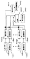
図13は、本発明の第3の実施の形態の運転支援装置のブロック図、図14はその変形例のブロック図、図15〜図17は、それらの動作を説明するための概略図である。図13および図14において、図7と同じ符号が付されたブロック要素は図7のブロック要素と同じ構成および機能を有する。 FIG. 13 is a block diagram of a driving support apparatus according to a third embodiment of the present invention, FIG. 14 is a block diagram of a modification thereof, and FIGS. 15 to 17 are schematic diagrams for explaining the operations thereof. . In FIG. 13 and FIG. 14, block elements having the same reference numerals as those in FIG. 7 have the same configuration and function as the block elements in FIG. 7.
本実施の形態では、図15(a)に示されているように、前記第1、2の実施の形態と同様に、垂直方向に所定の間隔をあけて設置された2つの撮像手段1001、3001から画像を入力する。この2つの入力画像は、それぞれ路面投影手段8001、8002において、路面データ手段3011のデータを基に、路面に投影された位置に仮想視点1004からの画像が合成される。
In the present embodiment, as shown in FIG. 15 (a), as in the first and second embodiments, two imaging means 1001, which are installed at a predetermined interval in the vertical direction, Input an image from 3001. The two input images are synthesized from the
このとき、路面より上に位置する後方の車両のバンパーの点9001は、上方の撮像手段3001からは、路面上に投影すると9002の方向に見え、下方の撮像手段1001からは、より遠方の9003の方向に見える。したがって、それぞれ合成される画像では、図15(b)、図15(c)に示されているように、路面上の白線は、同じ位置に合成されるが、路面より上に位置する後方の車両のバンパーの点9001などは異なる位置に合成される。
At this time, the
障害物領域検出手段8003は、この2つの合成画像の差を取り、一定以上の差のある領域を障害物領域として検出する。このとき検出される領域は、図15(d)に示されているように、路面より上に位置して、かつ元の撮像画像上で水平エッジを有する部分が、領域9004、領域9005のように検出される。
The obstacle
オーバーレイ手段8004では、この図16(a)に示されているように、図15(b)の画像に、図15(d)に示されている障害物領域を重ね合わせて合成する。このとき障害物領域9004、9005は画像上半透明の赤い膜として、図15(d)で車両の存在する領域に合成される。
In the
表示手段3009にはこのオーバーレイ手段8004の出力が表示される。運転者は、この合成画像を見ることで、従来例とは異なり、路面上の白線と障害物の区別を正確に把握することができる。また他の車両などの障害物までの自車両からの距離は正確ではないが、その方向は正確に把握することができるので、従来例と比較しても安全に車両を運転することができる。 The display means 3009 displays the output of the overlay means 8004. The driver can accurately grasp the distinction between the white line on the road surface and the obstacle, unlike the conventional example, by viewing the composite image. In addition, although the distance from the own vehicle to an obstacle such as another vehicle is not accurate, since the direction can be accurately grasped, the vehicle can be driven safely even compared to the conventional example.
さらに、この第3の実施の形態のバリエーションを図14、図16(b)〜(d)、および図17(a)〜図17(d)を用いて説明する。まず撮像手段1001、3001からの撮像画像は、それぞれレンズ歪み補正・距離・方向画像手段8005、8006で、それぞれ図16(b)に示されているように路面に投影したときの撮像手段からの距離Rと方向θで展開される座標上の画像に変換される。このとき撮像画像にレンズ歪みや取り付け角による歪みなどが含まれていた場合、この歪み量を予め計測しておき、変換時に同時に補正する。距離Rと方向θで展開される座標上の画像は、それぞれ図16(c)、図16(d)に示されているようになる。ここで、撮像手段3001からの画像が図16(c)、撮像手段1001からの画像が図16(d)で、路面上の白線などは同じ位置に合成されるが、バンパーなどのエッジ位置は16(d)の方が遠くに合成される。 Further, variations of the third embodiment will be described with reference to FIGS. 14, 16 (b) to (d), and FIGS. 17 (a) to 17 (d). First, the picked-up images from the image pickup means 1001 and 3001 are the lens distortion correction / distance / direction image means 8005 and 8006, respectively, and the image from the image pickup means when projected onto the road surface as shown in FIG. It is converted into an image on coordinates developed in the distance R and the direction θ. At this time, if the captured image includes lens distortion or distortion due to the mounting angle, the distortion amount is measured in advance and corrected simultaneously with the conversion. Images on coordinates developed in the distance R and the direction θ are as shown in FIGS. 16C and 16D, respectively. Here, the image from the imaging means 3001 is shown in FIG. 16 (c) and the image from the imaging means 1001 is shown in FIG. 16 (d). The white line on the road surface is synthesized at the same position, but the edge position of the bumper etc. 16 (d) is synthesized farther away.
エッジ比較手段8007では、このエッジ位置を図16(c)、図16(d)の走査線9008に従って比較する。走査線9008上の画像のエッジを示したものが図17(a)である。そして、この図において、図16(c)に対応するエッジ信号が9009、図16(d)に対応するエッジ信号が9010である。ここで走査線に従ってエッジ信号9009のエッジ9011を検出したとき、これと同じ位置にエッジ信号9010上のエッジ9012が存在するとき、これは路面上のエッジなので無視する。一方、エッジ信号9009のエッジ9013を検出し、かつこれと同じ位置にエッジ信号9010上のエッジが存在しないとき、次に検出されるエッジ9014までの距離dを検出し、このときのエッジ9013までの距離R1と、エッジ9013からエッジ9014までの距離dを距離推定手段8008へ出力する。
The edge comparison means 8007 compares the edge positions according to the
距離推定手段8008では、エッジ9013までの距離R1と、エッジ9013からエッジ9014までの距離dを基に実際の距離を推定する。図17(b)はその関係を示したものである。ここで、撮像手段1001の高さをH1、撮像手段1001から撮像手段3001までの高さの差をHdとし、前記入力のR1とdとから、実際の点の高さHと距離R’の関係は簡単な比例により下記2つの関係式[4]、[5]が求まる。
The distance estimation means 8008 estimates the actual distance based on the distance R1 to the
H*R1=(H1+Hd)*(R1−R’) …式[4] H * R1 = (H1 + Hd) * (R1-R ') Formula [4]
H*(R1+d)=H1*(R1+d−R’) …式[5] H * (R1 + d) = H1 * (R1 + d-R ') Formula [5]
これらの関係式より、実際の点の高さHと距離R’は下記式[6]、[7]のように推定される。 From these relational expressions, the height H and the distance R ′ of the actual point are estimated as the following expressions [6] and [7].
R’=R1*(R1+d)*Hd/{R1*Hd+d*(H1+Hd)}…式[6] R '= R1 * (R1 + d) * Hd / {R1 * Hd + d * (H1 + Hd)} Equation [6]
H=H1*(H1+Hd)*d/{Hd*R1+(H1+Hd)*d}…式[7] H = H1 * (H1 + Hd) * d / {Hd * R1 + (H1 + Hd) * d} Expression [7]
この推定された高さHと距離R’を障害物領域手段8009へ出力する。障害物領域手段8009は、この高さHが閾値以上のときの距離R’が入力されたとき、図17(c)に示されているように、走査線9008上の距離R’のところに線を引き、それより遠方を障害物領域と決定する。
The estimated height H and distance R ′ are output to the obstacle area means 8009. When the distance R ′ when the height H is equal to or greater than the threshold value is input, the obstacle area means 8009 is positioned at the distance R ′ on the
オーバーレイ手段8004では、図17(c)に示されているように、撮像手段3001からの変換画像である図16(c)の上に、この障害物領域をオーバーレイ合成する。
As shown in FIG. 17C, the
距離・方向・路面変換手段8010は、このオーバーレイ合成された画像の距離・方向展開された座標を通常の上方から見た路面の画像に変換し、表示手段3009へ出力する。
The distance / direction / road
表示手段3009に表示される画像は、図17(d)に示されているように、バンパーのような地面から離れた障害物でも実際の距離R1の位置に障害物領域として表示されるので、運転者はこれを見ることで、安全に運転することができる。 The image displayed on the display means 3009 is displayed as an obstacle area at an actual distance R1 even if the obstacle is far from the ground, such as a bumper, as shown in FIG. 17 (d). By seeing this, the driver can drive safely.
この実施の形態には以下の(1)〜(4)に記載したような利点がある。
(1)一度、距離・方向に展開した座標上に画像を変換するとき、カメラのレンズの歪みやカメラ取り付け角などの歪みを補正することができる。
This embodiment has advantages as described in the following (1) to (4).
(1) Once an image is converted to coordinates developed in the distance / direction, distortion such as camera lens distortion and camera mounting angle can be corrected.
(2)2つの入力画像同士で直接視差を検出するときは、これらの歪みを別途考慮する必要があるが、本実施の形態では、これを省略することができる。 (2) When directly detecting parallax between two input images, it is necessary to consider these distortions separately, but in this embodiment, this can be omitted.
(3)2つの撮像手段の視野角等が異なる場合も、同様にこの操作によってその違いの影響を吸収できる。 (3) Even when the viewing angles of the two image pickup means are different, the influence of the difference can be absorbed similarly by this operation.
(4)路面投影した後でエッジなどを比較する場合は、距離方向にエッジ比較を行う必要があるが、路面投影画像では距離方向は一定ではないので、実際のハードでのメモリアクセスが煩雑になり、また障害物領域を決定するときも距離方向が一定でないので同様に実際のハードでのメモリアクセスが煩雑になる。しかし、ここでは、画像を一度、距離・方向に展開した座標上に画像を変換した状態で、エッジ比較と障害物領域決定を行っている。この変換画像上では距離方向を座標軸としているので、上述の操作が実際のハードで非常に簡単に実現できる。 (4) When comparing edges after projecting road surfaces, it is necessary to compare edges in the distance direction. However, since the distance direction is not constant in the road surface projection image, memory access on actual hardware is complicated. In addition, since the distance direction is not constant when the obstacle area is determined, memory access in actual hardware is similarly complicated. However, here, edge comparison and obstacle region determination are performed in a state in which the image is converted into coordinates once developed in the distance and direction. Since the distance direction is used as a coordinate axis on this converted image, the above-described operation can be realized very easily with actual hardware.
このように、本発明の第3の実施の形態によれば、移動体に設置された複数の撮像手段で撮像された画像を上方の仮想視点からの画像に変換し、かつ変換された画像間で一致しない領域を障害物領域として検出し、その障害物領域を示す信号を前記変換画像信号に合成し、表示することにより、障害物までの距離と方向をより判り易く正確に提示する。したがって、運転者は、表示された画像を見ることで、車両周囲の障害物の位置関係と周囲状況を直感的かつ正確に確認することができる。 As described above, according to the third embodiment of the present invention, an image captured by a plurality of imaging means installed on a moving body is converted into an image from an upper virtual viewpoint, and the converted images A region that does not match is detected as an obstacle region, and a signal indicating the obstacle region is combined with the converted image signal and displayed, so that the distance and direction to the obstacle can be presented more easily and accurately. Therefore, the driver can intuitively and accurately confirm the positional relationship and surrounding conditions of obstacles around the vehicle by looking at the displayed image.
(第4の実施の形態)
本発明の第4の実施の形態の運転支援装置は、移動体に設置された撮像手段で撮像された画像を上方の仮想視点からの画像に変換し、かつその変換画像において正確で歪みの少ない部分を明るく合成し、歪みが大きく距離が不正確な部分が暗く合成することにより、運転者が画像中の信頼性の高い部分と低い部分とを直観的に把握できるようにしたものである。
(Fourth embodiment)
The driving support apparatus according to the fourth embodiment of the present invention converts an image captured by an imaging unit installed on a moving body into an image from an upper virtual viewpoint, and the converted image is accurate and has little distortion. By synthesizing the parts brightly and synthesizing the dark parts with large distortion and inaccurate distance, the driver can intuitively grasp the highly reliable part and the low part in the image.
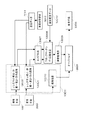
図18は、本発明の第4の実施の形態による運転支援装置のブロック図であり、図19は、その変形例のブロック図である。また、図20は、それらの動作を説明するための概略図である。図18および図19において、図7と同じ符号が付されたブロック要素は図7のブロック要素と同じ構成および機能を有する。 FIG. 18 is a block diagram of a driving support apparatus according to the fourth embodiment of the present invention, and FIG. 19 is a block diagram of a modification thereof. FIG. 20 is a schematic diagram for explaining these operations. 18 and 19, the block elements denoted by the same reference numerals as those in FIG. 7 have the same configuration and function as the block elements in FIG.
本実施の形態では、図18に示されているように1つの撮像手段1001から画像を入力する。そして、この入力画像を基に、画像投影手段10001において、路面データ手段3011のデータで路面に投影された位置に画像が合成されるが、このとき強度算出手段10002は、撮像手段1001のカメラパラメータ10003と路面データ手段3011のデータとの関係から路面へ投影する強度を算出し、決定する。
In the present embodiment, as shown in FIG. 18, an image is input from one
図20(a)に示されているように、撮像手段10001から1画素あたり一定の光線11001を仮定する。ここで、路面投影するときの強度Kを、その1画素が路面を投影する面積Aと、光線の路面への角度θから下記の式[8]のように計算する。
As shown in FIG. 20A, a
簡単に式[8]を説明すると、面積Aが大きいほど強度は減り、また路面への角度が垂直なほど強度は大きくなる。また強度は1.0でクリップされる。 To briefly explain equation [8], the strength decreases as the area A increases, and the strength increases as the angle to the road surface is vertical. Also, the strength is clipped at 1.0.
K’=α・sin(θ)/S …式[8]
if(K’>1.0) K=1.0elseK=K’ここで、αは増幅強度で定数
K ′ = α · sin (θ) / S (8)
if (K ′> 1.0) K = 1.0 elseK = K ′ where α is the amplification intensity and constant
この強度の算出により、図20(a)に示されているように、撮像手段1001の近辺の路面は、その強度が大きく、遠方は強度が小さくなる。この強度の値に従って合成された画像は、図20(b)に示されているように、撮像手段1001から一定の近辺の路面までは、強度Kが1.0であるので一定の明るさに合成され、そこから遠方に行くに従って、だんだん暗くなるように合成される。
By calculating the intensity, as shown in FIG. 20 (a), the road surface in the vicinity of the
撮像手段1001からの入力画像をこの強度に従って合成した画像は、図20(c)のように、歪みが大きく距離の誤差も大きい遠方の部分が暗く合成される。 An image obtained by synthesizing the input image from the imaging means 1001 according to this intensity is synthesized with a dark portion at a distant portion having a large distortion and a large distance error, as shown in FIG.
運転者は、この合成画像を見ることで、従来例とは異なり、誤差が少なく正確な近辺の部分の合成画像をはっきり見ることができ、誤差と歪みの多い遠方については暗く合成されているので、その明るさに応じた確かさしか有しない情報であることが直感的に認識できる。したがって、障害物までの距離を正確に把握することはできないが、合成画像中の部分部分の信頼度を直感的に把握でき、従来例と比較しても安全に車両を運転することができる。 By looking at this composite image, the driver can clearly see the composite image of the near part with little error and accurate, and the far side with much error and distortion is synthesized darkly. It can be intuitively recognized that the information has only certainty according to the brightness. Therefore, although the distance to the obstacle cannot be accurately grasped, the reliability of the partial portion in the composite image can be intuitively grasped, and the vehicle can be driven safely even compared with the conventional example.
図19に示されている変形例は、図18を複数の撮像手段を有するように拡張したものである。各撮像手段1001…10007の撮像画像は、それぞれのカメラパラメータ10003…10004と路面データ3011との関係から、強度算出手段10002…10005でそれぞれの路面投影への強度が算出・決定され、その強度に従って画像投影手段10001、10006で画像が合成される。
The modified example shown in FIG. 19 is obtained by extending FIG. 18 to include a plurality of imaging units. Based on the relationship between the
これらの路面投影合成された画像をさらに合成手段10007で1つの画像に合成する。このとき、それぞれの路面投影の強度に従った重みづけで合成が行われ、表示手段3009に表示される。表示される画像は、例えば図20(d)に示されているように、3つの撮像手段からの画像が1つの路面投影画像に合成されたものである。
These road surface projection combined images are further combined into one image by combining
このとき車両後方中央の撮像手段は高解像度なもので、左右の撮像手段は補助的なものとして低解像度なものを用いている。したがって、左右の撮像手段の投影する領域は1画素あたりの面積が大きいので、かなり近辺の領域しか明るく合成しない。一方、中央の撮像手段の投影する領域は1画素あたりの面積が比較的小さいので、遠方まで明るく合成できる。そして、両方の投影画像が重なる領域11002では、強度の大きい中央の撮像手段の投影画像が大きく重みづけられて合成されるので、より信頼性の高い画像が合成される。
At this time, the imaging means at the center of the rear of the vehicle has high resolution, and the left and right imaging means use auxiliary low-resolution imaging means. Therefore, since the area projected by the left and right imaging means has a large area per pixel, only a very near area is brightly combined. On the other hand, the area projected by the central imaging means has a relatively small area per pixel, so that it is possible to synthesize brightly far away. In the
運転者は、この合成画像を見ることで、複数の撮像手段からの合成画像であっても、画像中の部分部分の信頼度を直感的に把握でき、従来例と比較しても安全に車両を運転することができる。 By viewing this composite image, the driver can intuitively grasp the reliability of the partial portion in the image even if it is a composite image from a plurality of imaging means, and the vehicle can be safely compared with the conventional example Can drive.
このように、本発明の第4の実施の形態によれば、移動体に設置された撮像手段で撮像された画像を上方の仮想視点からの画像に変換し、かつその変換画像において正確で歪みの少ない部分を明るく合成し、歪みが大きく距離が不正確な部分が暗く合成することにより、運転者が画像中の信頼性の高い部分と低い部分を直感的に把握できるようにした。これにより、信頼性の低い部分の方向に車両を速く動かすといった危険な運転が防止され、その結果、より安全な運転を促すことができる。 As described above, according to the fourth embodiment of the present invention, the image captured by the imaging means installed on the moving body is converted into an image from the upper virtual viewpoint, and the converted image is accurately and distorted. By combining bright parts with low distortion and combining dark parts with large distortion and inaccurate distances, the driver can intuitively grasp the high and low reliability parts of the image. This prevents dangerous driving such as moving the vehicle quickly in the direction of the low-reliability portion, and as a result, safer driving can be promoted.
なお、以上説明した第4の実施の形態では、算出された強度にしたがって画像の明るさのみを変化させたが、それ以外にも色づけなどを変化させても良い。また強度の小さな部分について灰色や白色を混ぜることで、霧のような効果を出すこともでき、この場合でも運転者が強度の少ない方向へ車を速く移動させることを防止できるので、安全な運転を促すことができる。 In the fourth embodiment described above, only the brightness of the image is changed according to the calculated intensity, but coloring or the like may be changed in addition to that. It is also possible to produce a foggy effect by mixing gray or white with low intensity parts, and even in this case it is possible to prevent the driver from moving the car in a direction with less intensity so that driving is safe. Can be encouraged.
(第5の実施の形態)
本発明の第5の実施の形態運転支援装置は、撮像手段で撮像された画像を撮像手段からの距離または高さを座標とした中間画像に変換し、その中間画像間における一致しない領域の実際の距離を推定して位置を修正し、その修正された領域を障害物領域として検出し、その障害物領域を示す信号を中間画像中に合成し、この合成画像を通常座標画像に変換し、表示することにより、運転者が車両周囲の障害物の位置関係と周囲状況を直感的かつ正確に確認することができるようにしたものである。
(Fifth embodiment)
The driving support apparatus according to the fifth embodiment of the present invention converts an image captured by the image capturing unit into an intermediate image with the distance or height from the image capturing unit as a coordinate, and actually performs the non-matching region between the intermediate images. The position is corrected by estimating the distance of the detected area, the corrected area is detected as an obstacle area, a signal indicating the obstacle area is synthesized in the intermediate image, and the synthesized image is converted into a normal coordinate image. By displaying the information, the driver can intuitively and accurately confirm the positional relationship and surrounding conditions of the obstacles around the vehicle.
図21は本発明の第5の実施の形態による運転支援装置のブロック図であり、図22〜26はその動作を説明するための図であり、図27は探索処理を説明するためのフローチャートである。図21において、図7と同じ符号が付されたブロック要素は図7のブロック要素と同じ構成および機能を有する。 FIG. 21 is a block diagram of a driving support apparatus according to a fifth embodiment of the present invention, FIGS. 22 to 26 are diagrams for explaining the operation, and FIG. 27 is a flowchart for explaining a search process. is there. In FIG. 21, the block elements denoted by the same reference numerals as those in FIG. 7 have the same configuration and function as the block elements in FIG.
本実施の形態では、撮像手段1001、3001は魚眼レンズを有し、その撮像画像はレンズ歪み補正・距離−高さ・方向画像手段13005、13006にそれぞれ入力される。レンズ歪み補正・距離−高さ・方向画像手段13005、13006では、入力画像は図22(1)に示されているように、撮像手段からの所定の距離Rmaxまでは路面に投影し、それ以遠は円筒に投影したと仮定し、図22(b)に示されているように、このときの路面上の距離Rまたは円筒上の高さHと方向θとで展開される座標の変換画像に変換される。 In the present embodiment, the imaging means 1001 and 3001 have fisheye lenses, and the captured images are input to the lens distortion correction / distance-height / direction image means 13005 and 13006, respectively. In the lens distortion correction / distance-height / direction image means 13005, 13006, as shown in FIG. 22 (1), the input image is projected onto the road surface up to a predetermined distance Rmax from the image pickup means, and beyond. Is projected onto a cylinder, and as shown in FIG. 22 (b), a converted image of coordinates developed by the distance R on the road surface at this time or the height H on the cylinder and the direction θ is used. Converted.
このとき撮像画像にレンズ歪みや取り付け角による歪みなどが含まれていた場合、この歪み量を予め計測しておき変換時に同時に補正する。例えば、図23(a)、(b)に示されている撮像画像図は、それぞれ同図(c)、(d)に示されているようになる。ここでは、前記路面上の所定の距離Rmax=300cmであり、また、図22(a)に示されているRmin=0cm、Hmax=200cmである。 At this time, if the captured image includes lens distortion or distortion due to the mounting angle, the distortion amount is measured in advance and corrected simultaneously with the conversion. For example, the captured image diagrams shown in FIGS. 23 (a) and 23 (b) are as shown in FIGS. 23 (c) and (d), respectively. Here, the predetermined distance Rmax = 300 cm on the road surface, and Rmin = 0 cm and Hmax = 200 cm shown in FIG. 22 (a).
エッジ抽出手段13007では、前記それぞれの変換画像について垂直方向に5画素離れた信号の差分をとる操作により、水平エッジを抽出する。図24(a)、(b)にそれぞれレンズ歪み補正・距離−高さ・方向画像手段13005、13006の出力の変換画像の水平エッジが抽出された画像の様子を示す。ここで、図24(a)が上方の撮像手段3001からのものであり、図24(b)が他方のものである。図の中で破線14007で示されているように、垂直に近い斜めのエッジは弱められ、太い実線14008で示されているように、水平エッジは強調される。
The
水平ブロックマッチング・距離推定手段13008は、このエッジ位置を走査線14001に従って走査し、エッジの極大点14002を検出すると、その極大点を中心とした縦横10画素の範囲のブロック14003の画像信号を記憶する。
The horizontal block matching / distance estimating means 13008 scans the edge position in accordance with the scanning line 14001 and, when detecting the edge
次に、図24(b)に示されているエッジ画像について、前記走査線14001と同じ水平位置の走査線14004上で、図21に示されている探索範囲データ手段13012に従った範囲で、前記記憶したブロック14003と最も類似したデータを持つブロック14006を検出する。このとき、ブロック14006の中心点14005と前記エッジの極大点14002の垂直位置との差を変換画像上での視差データとして距離が推定される。
Next, for the edge image shown in FIG. 24 (b), on the
このときの、探索範囲データ手段13012と、水平ブロックマッチング・距離推定手段13008の動作を、図27のフロー図を基にしてさらに詳しく説明する。探索範囲データ手段13012には、ブロック14003の中心位置14002の垂直位置に対応したデータが格納されている。図25(a)の点14013に示されているように、上方の撮像手段3001から見た点14002の位置が路面に対応している場合(点14002の位置が、図24(a)のRmaxより下の場合)、路面上の点14013と撮像手段からの距離50cmの点14014とをそれぞれ下方の撮像手段1001で見たときの変換画像上(図25(b))での垂直位置14015、14016が探索範囲データ手段13012に記憶されている(ただし、このとき、路面上の点14013を下方の撮像手段1001で見たときの垂直位置14015は、両画像とも路面を仮定して変換画像を合成しているので点14002の垂直位置と同じになる。)。
The operations of the search range data means 13012 and the horizontal block matching / distance estimation means 13008 at this time will be described in more detail based on the flowchart of FIG. The search range data means 13012 stores data corresponding to the vertical position of the
また、図25(a)に示されているように、上方の撮像手段3001から見た点14002の位置が円筒に対応している場合(点14002の位置が、図24(a)のRmaxより上の場合)、無限遠点14017と円筒上の点14018と撮像手段からの距離50cmの点14019とをそれぞれ下方の撮像手段1001で見たときの変換画像上での垂直位置14020、14021、14022が探索範囲データ手段13012に記憶されている(ただし、このときも、円筒上の点14018を下方の撮像手段1001で見たときの垂直位置14021は、両画像とも円筒を仮定して変換画像を合成しているので点14002の垂直位置と同じになる。)。
In addition, as shown in FIG. 25A, when the position of the
これらの探索範囲データを元に、図27に示されているフローに従って、探索処理が行われる。 Based on these search range data, a search process is performed according to the flow shown in FIG.
まず、点14002の位置が路面に対応するか円筒に対応するかを判断する(ステップS1)。
First, it is determined whether the position of the
そして、路面に対応すると判断した場合(ステップS1でYES)、まず垂直位置14015でブロックの信号の差の絶対値の集計(SAD)を求め(ステップS2)、そのSAD値が閾値THよりも小さい場合(ステップS3でYES)、ブロックデータが一致したと判断し、この場合、点14002の水平エッジは路面上のエッジであるとの判断出力を行って処理を終わる(ステップS4)。前記SAD値が閾値THよりも大きい場合(ステップS3でNO)、垂直位置14015から14016の範囲でSAD値が最小となる位置を探索する(ステップS5)。最小となったSAD値が閾値THよりも小さい場合(ステップS6でYES)、その位置と点14002の垂直位置との差を視差データとして距離と路面からの高さが求まるので、それを出力して処理を終わる(ステップS7)。最小となったSAD値が閾値THよりも大きい場合(ステップS6でNO)、一致する水平エッジが存在しないとの判断出力を行って処理を終わる(ステップS8)。
If it is determined that it corresponds to the road surface (YES in step S1), first, an absolute value summation (SAD) of the block signal difference is obtained at the vertical position 14015 (step S2), and the SAD value is smaller than the threshold value TH. In this case (YES in step S3), it is determined that the block data match. In this case, the determination is made that the horizontal edge at the
円筒に対応すると判断した場合(ステップS1でNO)、まず垂直位置14020から14021までの範囲でSAD値の最小値を求め(ステップS9)、そのSAD値の最小値が閾値THよりも小さい場合(ステップS10でYES)、ブロックデータが一致したと判断し、この場合、点14002の水平エッジは円筒までの距離Rmaxより遠方であるとの判断出力を行って処理を終わる(ステップS11)。前記SAD値が閾値THよりも大きい場合(ステップS10でNO)、垂直位置14021から14022の範囲でSAD値が最小となる位置を探索する(ステップS12)。最小となったSAD値が閾値THよりも小さい場合(ステップS13でYES)、その位置と14002の垂直位置との差を視差データとして距離と路面からの高さが求まるので、それを出力して処理を終わる(ステップS14)。最小となったSAD値が閾値THよりも大きい場合(ステップS13でNO)、一致する水平エッジが存在しないとの判断出力を行って処理を終わる(ステップS15)。
When it is determined that it corresponds to a cylinder (NO in step S1), first, the minimum value of the SAD value is obtained in the range from the
以上の処理フローによって、障害物と関係ない、路面上や遠方の水平エッジは、少ない処理で判断・除去でき、障害物に関係するエッジのみ多くの処理が発生するので、全体的に非常に少ない処理で、障害物に関係するエッジの距離と高さが算出できる。 With the above processing flow, road edges and distant horizontal edges that are not related to obstacles can be judged and removed with a small amount of processing, and only a lot of processing related to obstacles is generated, so there is very little overall. In the process, the distance and height of the edge related to the obstacle can be calculated.
障害物境界手段13009では、図27に示されているように、距離と高さが検出された水平エッジについて、その高さが20cm以上のものを障害物のエッジと判断し、図25(c)に示されているように、距離R’の場所に線を引き、その結果、水平エッジの集合は障害物境界を示す線14023となる。
As shown in FIG. 27, the obstacle boundary means 13009 determines that a horizontal edge whose distance and height are detected has a height of 20 cm or more as an edge of the obstacle, and FIG. ), A line is drawn at the location of the distance R ′, so that the set of horizontal edges becomes a
画像投影手段13010では、別途撮像手段3001の画像を基に直接上方仮想視点から見た画像が合成され、オーバーレイ手段13004では、図25(c)に示されているように、画像投影手段13010から画像の上に、この障害物をオーバーレイ合成する。
In the
このオーバーレイ合成された画像が、表示手段3009に表示される。表示される画像は、図25(c)に示されているように、バンパーのように地面から離れた障害物が存在しても実際の距離の位置に障害物境界の線が表示されるので、運転者はこれを見ることで安全に運転することができる。 This overlay synthesized image is displayed on the display means 3009. As shown in FIG. 25 (c), the displayed image is such that an obstacle boundary line is displayed at the actual distance even if there is an obstacle away from the ground such as a bumper. By seeing this, the driver can drive safely.
この実施の形態には以下の(1)〜(8)に記載したような利点がある。
(1)一度、距離・方向に展開した座標上に画像を変換するとき、撮像手段のレンズの歪みや撮像手段の取り付け角などの歪みを補正することができる。
This embodiment has advantages as described in the following (1) to (8).
(1) Once an image is converted to coordinates developed in the distance / direction, distortion such as lens distortion of the imaging means and attachment angle of the imaging means can be corrected.
(2)2つの入力画像同士で直接視差を検出するときは、これらの歪みを別途勘案する必要があるが、これを省くことができる。 (2) When parallax is directly detected between two input images, it is necessary to consider these distortions separately, but this can be omitted.
(3)2つの撮像手段の視野角等が異なる場合も、同様にこの操作によってその違いの影響を吸収することができる。 (3) Even when the viewing angles of the two imaging means are different, the influence of the difference can be absorbed by this operation as well.
(4)また、図22(a)に示されているように、路面に加えて円筒を仮定した変換画像を用いることで、撮像手段に対し高い位置にあるため路面投影画像では現れないような障害物も検出でき、表示画像上にその障害物境界線を表示することができる。 (4) Also, as shown in FIG. 22 (a), by using a converted image assuming a cylinder in addition to the road surface, it does not appear in the road surface projection image because it is at a high position relative to the imaging means. An obstacle can also be detected, and the boundary line of the obstacle can be displayed on the display image.
(5)図27に示されている処理フローによって、障害物と関係ない、路面上や遠方の水平エッジは、少ない処理で判断・除去でき、障害物に関係するエッジのみ多くの処理が発生するので、全体的に非常に少ない処理で、障害物に関係するエッジの距離と高さが算出できる。 (5) According to the processing flow shown in FIG. 27, a horizontal edge on the road surface or far away, which is not related to an obstacle, can be judged and removed with a small amount of processing, and a large amount of processing occurs only for the edge related to the obstacle. Therefore, the distance and height of the edge related to the obstacle can be calculated with very little overall processing.
(6)探索範囲データ手段13012を設けることで、必要な範囲だけ探索できるので、全体的に非常に少ない処理で、障害物に関係するエッジの距離と高さが算出できる。 (6) Since only the necessary range can be searched by providing the search range data means 13012, the distance and height of the edge related to the obstacle can be calculated with very little overall processing.
(7)図22(a)に示されているように、路面に加えて円筒を仮定した変換画像を用いることで、探索範囲データは水平エッジ14002の垂直位置のみで決定され、水平位置には依存しないので、そのメモリ量を非常に少なくすることができる。
(7) As shown in FIG. 22 (a), by using a converted image assuming a cylinder in addition to the road surface, the search range data is determined only by the vertical position of the
例えば、従来のように魚眼レンズを有する撮像手段の画像をそのまま用いてステレオマッチングを行う場合、その探索範囲は図26に示されているように、画面の垂直位置と水平位置に依存した曲線14024、14025になってしまう。この曲線のデータを記憶するためには非常に多くのメモリを必要とする。本実施の形態では、このメモリを非常に少なくすることができ、かつ単純な構成で実現できる。
For example, when performing stereo matching using an image of an imaging unit having a fisheye lens as it is conventionally, the search range is a
(8)従来のステレオマッチングでは、この曲線の位置は、厳密には画素単位以下の精度を必要とするが、実際の探索におけるSAD値の算出においては、画素単位の位置精度でしか求めることができないので、この量子化ノイズが悪影響を及ぼす。本実施の形態では、その悪影響も回避することができる。 (8) In the conventional stereo matching, the position of this curve strictly requires the accuracy of the pixel unit or less, but in the calculation of the SAD value in the actual search, it can be obtained only with the position accuracy of the pixel unit. This quantization noise has an adverse effect because it cannot. In this embodiment, the adverse effect can be avoided.
図28(a)〜(c)は、第5の実施の形態のバリエーションを説明するものである。図22(a)、(b)に示されている路面と円筒の投影面の代わりに、図28(a)、(b)に示されているように上方の撮像手段3001の位置を中心とした球面を投影面としてもよい。また、図28(c)に示されているように、変換画像の横軸は必ずしも角度θでなくてもよく、関数F(θ)で圧縮したものでも良い。 FIGS. 28A to 28C illustrate variations of the fifth embodiment. Instead of the road surface and the cylindrical projection surface shown in FIGS. 22 (a) and 22 (b), the position of the upper imaging means 3001 is centered as shown in FIGS. 28 (a) and 28 (b). The spherical surface obtained may be used as the projection surface. Further, as shown in FIG. 28 (c), the horizontal axis of the converted image does not necessarily have to be the angle θ, and may be the one compressed by the function F (θ).
図29(a)は、第5の実施の形態の別のバリエーションを説明するものである。ここで、上方の撮像手段3001の解像度は640x480画素のものとし、ステレオマッチングにしか使用しない下方の撮像手段1001は320x480画素とする。このことで、表示用の合成画像は高解像度で、かつ障害物境界は必要十分な精度で検出でき、撮像手段の構成を安価なものにできる。 FIG. 29A illustrates another variation of the fifth embodiment. Here, the upper imaging means 3001 has a resolution of 640 × 480 pixels, and the lower imaging means 1001 used only for stereo matching has 320 × 480 pixels. As a result, the composite image for display can be detected with high resolution and the obstacle boundary can be detected with sufficient and sufficient accuracy, and the configuration of the imaging means can be made inexpensive.
図29(b)は、第5の実施の形態のさらに別のバリエーションを説明するものである。撮像手段3001、1001の同じ軸上に撮像手段18001を加え、障害物と検知されたエッジについて、さらに撮像手段18001の画像をもって検証することによって、ノイズを低減できるようにした。 FIG. 29B illustrates still another variation of the fifth embodiment. The image pickup means 18001 is added on the same axis of the image pickup means 3001 and 1001, and the edge detected as an obstacle is further verified with the image of the image pickup means 18001 so that noise can be reduced.
図29(c)は、第5の実施の形態のさらに別のバリエーションを説明するものである。撮像手段3001、1001の軸上とは別位置に撮像手段18002を加えることによって、水平エッジ以外の垂直エッジも使用して障害物を検知することができるようにした。 FIG. 29 (c) explains yet another variation of the fifth embodiment. By adding imaging means 18002 at a position different from the axis of imaging means 3001 and 1001, obstacles can be detected using vertical edges other than horizontal edges.
図30(a)〜(c)は、第1〜第5の実施の形態において、上下2つのカメラで構成していたステレオ画像の撮像を1つのカメラで構成したものである。図30(a)は、レンズ1904の前に複数の鏡1901〜1903を配置することにより、1つの撮像面1905上の左右に、それぞれ視差のあるステレオ画像を得るものである。また、図30(b)は、2つの凸面鏡1906、1907をカメラ1908で撮像することによって、実質上、上下に視差のある画像を得るものである。そして、図30(c)は、図30(b)のカメラ1908で撮像される画像を示すもので、画面1909には、上に位置する凸面鏡1907で写した画像1910と、下に位置する凸面鏡1906で写した画像1911とが表示される。
FIGS. 30 (a) to 30 (c) show a configuration in which a single camera is used to capture a stereo image that has been configured with two upper and lower cameras in the first to fifth embodiments. In FIG. 30A, a plurality of
ここで、凸面鏡1906、1907の曲率を調節することによって、撮像範囲と撮像画像の解像度を調節することができる(垂直方向と水平方向を独立に調節することもできる)。
Here, by adjusting the curvatures of the
また、図30(b)では、凸面鏡1906と1907で撮像される角度の範囲はほぼ同じであるが、凸面鏡1906は凸面鏡1907に比較して曲率が大きく、小さな鏡で同じ範囲を撮像できるようになっており、このため、画面1909で画像1911は画像1910より小さく写っている。その結果、画像1910は高解像度であり、画像1911は比較的低解像度となる。画像1911は、視点変換の合成画像用に用いられ、画像1910はステレオ解析のみに用いられる。
In FIG. 30B, the range of angles captured by the
つまり、この合成によって、前述した図29の第5の実施の形態の別のバリエーションで説明したものと同様に、表示用の合成画像は高解像度で、かつ障害物領域は必要十分な精度で検出でき、カメラおよび画像処理装置を安価なものにできる。 That is, by this synthesis, the composite image for display is detected with high resolution and the obstacle area is detected with sufficient and sufficient accuracy, as described in the other variation of the fifth embodiment of FIG. The camera and the image processing apparatus can be made inexpensive.
以上図30(a)〜(c)を用いて説明したように、第1〜第5の実施の形態において、上下2つのカメラで構成していたステレオ画像の撮像を凸面鏡や反射鏡を用いて、1つのカメラで構成してもよい。 As described above with reference to FIGS. 30 (a) to 30 (c), in the first to fifth embodiments, a stereo image taken up by two upper and lower cameras is picked up using a convex mirror or a reflecting mirror. A single camera may be used.
なお、上述した第1〜第5の実施の形態においては、本発明の運転支援装置は、主として、後方の画像を生成するものであるとして説明したが、これに限るものではなく、前方や側方での画像を生成するものとしても良い。 In the first to fifth embodiments described above, the driving support device of the present invention has been described mainly as generating a rear image, but the present invention is not limited to this, and the front and side It is good also as what produces | generates the image in one.
また、上述した第1の実施の形態においては路面モデルを用いた仮想視点による画像合成を基にした例を説明し、第2の実施の形態においては路面モデルを用いた上方からの直交投影による画像合成を基にした例を説明したが、これはそれぞれ他方のものを基にしても良く、その場合でも本発明の運転支援装置の効果は変わりなく得られる。 In the first embodiment described above, an example based on image synthesis using a virtual viewpoint using a road surface model will be described. In the second embodiment, orthogonal projection from above using a road surface model will be described. Although an example based on image synthesis has been described, this may be based on the other, and even in that case, the effect of the driving support device of the present invention can be obtained without change.
さらに、本実施の形態の運転支援装置の各手段の機能の全部または一部をコンピュータに実行させるプログラムを用いて実現できる。 Furthermore, it is realizable using the program which makes a computer perform all or one part of the function of each means of the driving assistance device of this Embodiment.
本発明の運転支援装置は、自動車の運転を支援する装置として最適である。 The driving support device of the present invention is optimal as a device that supports driving of an automobile.
1001 撮像手段
3001 撮像手段
3002 水平エッジ抽出手段
3003 水平エッジ抽出手段
3004 ブロック設定手段
3005 探索手段
3006 サブピクセル推定・信頼性判定手段
3007 3Dマップ作成手段
3008 3D画像合成手段
3009 表示手段
3010 デフォルト視差データ手段
3011 路面データ手段
3012 車両姿勢情報手段
3013 画像投影手段
3014 障害物エッジ距離手段
3015 障害物領域手段
3016 オーバーレイ手段
7013 画像投影手段
8001 画像投影手段
8002 画像投影手段
8003 障害物領域検出手段
8004 オーバーレイ手段
8005 レンズ歪み補正・距離・方向画像手段
8006 レンズ歪み補正・距離・方向画像手段
8007 エッジ比較手段
8008 距離推定手段
8009 障害物領域手段
8010 距離・方向・路面変換手段
10001 画像投影手段
10002 強度算出手段
10005 強度算出手段
10006 画像投影手段
10007 撮像手段
13004 オーバーレイ手段
13005 レンズ歪み補正・距離−高さ・方向画像手段
13006 レンズ歪み補正・距離−高さ・方向画像手段
13007 エッジ抽出手段
13008 ブロックマッチング・距離推定手段
13009 障害物境界手段
13012 探索範囲データ手段
1001 Imaging means
3001 Imaging means
3002 Horizontal edge extraction means
3003 Horizontal edge extraction means
3004 Block setting method
3005 Search means
3006 Subpixel estimation / reliability judgment means
3007 3D map creation means
3008 3D image composition means
3009 Display means
3010 Default parallax data means
3011 Road surface data means
3012 Vehicle attitude information means
3013 Image projection means
3014 Obstacle edge distance means
3015 Obstacle area means
3016 Overlay means
7013 Image projection means
8001 Image projection means
8002 Image projection means
8003 Obstacle area detection means
8004 Overlay means
8005 Lens distortion correction / distance / direction image means
8006 Lens distortion correction / distance / direction image means
8007 Edge comparison means
8008 Distance estimation means
8009 Obstacle area means
8010 Distance / direction / road surface conversion means
10001 Image projection means
10002 Strength calculation means
10005 Strength calculation means
10006 Image projection means
10007 Imaging means
13004 Overlay means
13005 Lens distortion correction / distance-height / direction image means
13006 Lens distortion correction / distance-height / direction image means
13007 Edge extraction means
13008 Block matching / distance estimation means
13009 Obstacle boundary means
13012 Search range data means
Claims (7)
前記撮像手段により撮像された路面を含む複数の画像から視差データを算出する算出手段と、
前記撮像手段の入力画像から検出した視差と前記視差データとに基づいて、前記路面を含む画像における所定の位置が路面に存在するか路面より上に存在するか判定し、前記路面より上に存在する位置について前記撮像手段からの距離値を求め、前記路面より上に存在する位置に挟まれた領域を抽出する抽出手段と、
前記領域を挟む前記路面より上に存在する位置の距離値を線形補間して、前記撮像手段から前記領域までの第1の距離データを算出する設定手段と、
を備える運転支援装置。 A driving assistance device that assists driving by using distance data from the imaging means to an obstacle obtained based on an image taken by an imaging means,
Calculation means for calculating the parallax data from a plurality of images including the captured road surface by the imaging means,
Based on the parallax detected from the input image of the imaging means and the parallax data, it is determined whether a predetermined position in the image including the road surface exists on the road surface or above the road surface, and exists above the road surface. An extraction means for obtaining a distance value from the imaging means for a position to be extracted, and extracting an area sandwiched between positions above the road surface;
Setting means for the distance value of the position that is present above the road surface sandwiching the region by linear interpolation, and calculates a first distance data from the imaging means to said region,
A driving support apparatus comprising:
請求項1に記載の運転支援装置。 The extraction unit determines that the predetermined position exists on the road surface when an edge at the predetermined position in the image including the road surface matches the parallax data, and determines that the predetermined position exists when the edge does not match the parallax data. Determine that the position is above the road surface,
The driving support device according to claim 1.
請求項1に記載の運転支援装置。 The extraction unit sets second distance data from the imaging unit to a position existing on the road surface based on the parallax data for a position existing on the road surface.
The driving support device according to claim 1.
請求項3に記載の運転支援装置。 The image processing apparatus further includes synthesis means for generating image data obtained by performing viewpoint conversion on the captured image based on the first distance data and the second distance data .
The driving support device according to claim 3.
請求項4に記載の運転支援装置。 A display unit for displaying the image data generated by the combining unit;
The driving support device according to claim 4.
算出手段は、前記撮像手段により撮像された路面を含む複数の画像から視差データを算出し、The calculating means calculates parallax data from a plurality of images including the road surface imaged by the imaging means,
抽出手段は、前記撮像手段の入力画像から検出した視差と前記視差データとに基づいて、前記路面を含む画像における所定の位置が路面に存在するか路面より上に存在するか判定し、前記路面より上に存在する位置について前記撮像手段からの距離値を求め、前記路面より上に存在する位置に挟まれた領域を抽出し、The extraction unit determines whether a predetermined position in the image including the road surface exists on the road surface or above the road surface based on the parallax detected from the input image of the imaging unit and the parallax data, and the road surface Find the distance value from the imaging means for the position that exists above, extract the region sandwiched by the position that exists above the road surface,
設定手段は、前記領域を挟む前記路面より上に存在する位置の距離値を線形補間して、前記撮像手段から前記領域までの距離データを算出する、The setting means linearly interpolates a distance value of a position existing above the road surface across the area, and calculates distance data from the imaging means to the area.
運転支援方法。Driving support method.
前記撮像手段により撮像された路面を含む複数の画像から視差データを算出する算出手段と、Calculation means for calculating parallax data from a plurality of images including a road surface imaged by the imaging means;
前記撮像手段の入力画像から検出した視差と前記視差データとに基づいて、前記路面を含む画像における所定の位置が路面に存在するか路面より上に存在するか判定し、前記路面より上に存在する位置について前記撮像手段からの距離値を求め、前記路面より上に存在する位置に挟まれた領域を抽出する抽出手段と、Based on the parallax detected from the input image of the imaging means and the parallax data, it is determined whether a predetermined position in the image including the road surface exists on the road surface or above the road surface, and exists above the road surface. An extraction means for obtaining a distance value from the imaging means for a position to be extracted, and extracting an area sandwiched between positions above the road surface;
前記領域を挟む前記路面より上に存在する位置の距離値を線形補間して、前記撮像手段から前記領域までの距離データを算出する設定手段と、A setting means for linearly interpolating a distance value of a position existing above the road surface across the area, and calculating distance data from the imaging means to the area;
を備える演算装置。An arithmetic device comprising:
Priority Applications (1)
| Application Number | Priority Date | Filing Date | Title |
|---|---|---|---|
| JP2011215994A JP5083443B2 (en) | 2001-03-28 | 2011-09-30 | Driving support device and method, and arithmetic device |
Applications Claiming Priority (3)
| Application Number | Priority Date | Filing Date | Title |
|---|---|---|---|
| JP2001093721 | 2001-03-28 | ||
| JP2001093721 | 2001-03-28 | ||
| JP2011215994A JP5083443B2 (en) | 2001-03-28 | 2011-09-30 | Driving support device and method, and arithmetic device |
Related Parent Applications (1)
| Application Number | Title | Priority Date | Filing Date |
|---|---|---|---|
| JP2001244275A Division JP4861574B2 (en) | 2001-03-28 | 2001-08-10 | Driving assistance device |
Publications (2)
| Publication Number | Publication Date |
|---|---|
| JP2012019552A JP2012019552A (en) | 2012-01-26 |
| JP5083443B2 true JP5083443B2 (en) | 2012-11-28 |
Family
ID=45604384
Family Applications (1)
| Application Number | Title | Priority Date | Filing Date |
|---|---|---|---|
| JP2011215994A Expired - Lifetime JP5083443B2 (en) | 2001-03-28 | 2011-09-30 | Driving support device and method, and arithmetic device |
Country Status (1)
| Country | Link |
|---|---|
| JP (1) | JP5083443B2 (en) |
Families Citing this family (6)
| Publication number | Priority date | Publication date | Assignee | Title |
|---|---|---|---|---|
| US20130293678A1 (en) * | 2012-05-02 | 2013-11-07 | Harman International (Shanghai) Management Co., Ltd. | Virtual navigation system for video |
| JP6015276B2 (en) * | 2012-09-19 | 2016-10-26 | 日産自動車株式会社 | Camera mounting error correction apparatus and camera mounting error correction method |
| JP6453645B2 (en) * | 2014-12-25 | 2019-01-16 | 京セラ株式会社 | Stereo camera device, moving object, stereo camera system, server device, and control method |
| US10313584B2 (en) * | 2017-01-04 | 2019-06-04 | Texas Instruments Incorporated | Rear-stitched view panorama for rear-view visualization |
| JP2018191061A (en) * | 2017-04-28 | 2018-11-29 | アイシン精機株式会社 | Periphery monitoring device |
| JP7263731B2 (en) * | 2018-10-26 | 2023-04-25 | 株式会社デンソー | Image processing device |
Family Cites Families (6)
| Publication number | Priority date | Publication date | Assignee | Title |
|---|---|---|---|---|
| JPH0396451A (en) * | 1989-09-11 | 1991-04-22 | Nissan Motor Co Ltd | Obstruction detection device for vehicle |
| JP3381351B2 (en) * | 1993-12-24 | 2003-02-24 | 日産自動車株式会社 | Ambient situation display device for vehicles |
| JP3501841B2 (en) * | 1994-05-11 | 2004-03-02 | 株式会社デンソー | Three-dimensional object region detection device, distance measuring device to three-dimensional object region, and their detection and measurement method |
| JP3556319B2 (en) * | 1995-04-10 | 2004-08-18 | 富士通株式会社 | Distance measuring device |
| JPH08305999A (en) * | 1995-05-11 | 1996-11-22 | Hitachi Ltd | On-vehicle camera system |
| US7307655B1 (en) * | 1998-07-31 | 2007-12-11 | Matsushita Electric Industrial Co., Ltd. | Method and apparatus for displaying a synthesized image viewed from a virtual point of view |
-
2011
- 2011-09-30 JP JP2011215994A patent/JP5083443B2/en not_active Expired - Lifetime
Also Published As
| Publication number | Publication date |
|---|---|
| JP2012019552A (en) | 2012-01-26 |
Similar Documents
| Publication | Publication Date | Title |
|---|---|---|
| JP4861574B2 (en) | Driving assistance device | |
| US7728879B2 (en) | Image processor and visual field support device | |
| US7110021B2 (en) | Vehicle surroundings monitoring device, and image production method/program | |
| JP5729158B2 (en) | Parking assistance device and parking assistance method | |
| JP4406381B2 (en) | Obstacle detection apparatus and method | |
| EP2437494B1 (en) | Device for monitoring area around vehicle | |
| US9672432B2 (en) | Image generation device | |
| JP5615441B2 (en) | Image processing apparatus and image processing method | |
| JP5083443B2 (en) | Driving support device and method, and arithmetic device | |
| WO2017069191A1 (en) | Calibration apparatus, calibration method, and calibration program | |
| JP5953824B2 (en) | Vehicle rear view support apparatus and vehicle rear view support method | |
| US20090268027A1 (en) | Driving Assistance System And Vehicle | |
| US20090015675A1 (en) | Driving Support System And Vehicle | |
| JP2009129001A (en) | Operation support system, vehicle, and method for estimating three-dimensional object area | |
| WO2009119110A1 (en) | Blind spot display device | |
| JP4248570B2 (en) | Image processing apparatus and visibility support apparatus and method | |
| JP4872769B2 (en) | Road surface discrimination device and road surface discrimination method | |
| EP2061234A1 (en) | Imaging apparatus | |
| JP6392693B2 (en) | Vehicle periphery monitoring device, vehicle periphery monitoring method, and program | |
| JP7072641B2 (en) | Road surface detection device, image display device using road surface detection device, obstacle detection device using road surface detection device, road surface detection method, image display method using road surface detection method, and obstacle detection method using road surface detection method | |
| JP2004240480A (en) | Operation support device | |
| JP3521859B2 (en) | Vehicle peripheral image processing device and recording medium | |
| KR20190067578A (en) | Collision warning device and method using heterogeneous cameras having overlapped capture area | |
| JP2007134961A (en) | Vehicle detection device and display device for vehicle using the same | |
| JP3683258B2 (en) | Vehicle periphery monitoring device, image generation method, and image generation program |
Legal Events
| Date | Code | Title | Description |
|---|---|---|---|
| RD03 | Notification of appointment of power of attorney |
Free format text: JAPANESE INTERMEDIATE CODE: A7423 Effective date: 20120426 |
|
| A871 | Explanation of circumstances concerning accelerated examination |
Free format text: JAPANESE INTERMEDIATE CODE: A871 Effective date: 20120427 |
|
| RD05 | Notification of revocation of power of attorney |
Free format text: JAPANESE INTERMEDIATE CODE: A7425 Effective date: 20120508 |
|
| A975 | Report on accelerated examination |
Free format text: JAPANESE INTERMEDIATE CODE: A971005 Effective date: 20120525 |
|
| A131 | Notification of reasons for refusal |
Free format text: JAPANESE INTERMEDIATE CODE: A131 Effective date: 20120529 |
|
| A521 | Written amendment |
Free format text: JAPANESE INTERMEDIATE CODE: A523 Effective date: 20120718 |
|
| TRDD | Decision of grant or rejection written | ||
| A01 | Written decision to grant a patent or to grant a registration (utility model) |
Free format text: JAPANESE INTERMEDIATE CODE: A01 Effective date: 20120807 |
|
| A01 | Written decision to grant a patent or to grant a registration (utility model) |
Free format text: JAPANESE INTERMEDIATE CODE: A01 |
|
| A61 | First payment of annual fees (during grant procedure) |
Free format text: JAPANESE INTERMEDIATE CODE: A61 Effective date: 20120820 |
|
| R151 | Written notification of patent or utility model registration |
Ref document number: 5083443 Country of ref document: JP Free format text: JAPANESE INTERMEDIATE CODE: R151 |
|
| FPAY | Renewal fee payment (event date is renewal date of database) |
Free format text: PAYMENT UNTIL: 20150914 Year of fee payment: 3 |
|
| EXPY | Cancellation because of completion of term |