EP1223066A2 - Method of regulating and controlling an internal combustion engine - Google Patents
Method of regulating and controlling an internal combustion engine Download PDFInfo
- Publication number
- EP1223066A2 EP1223066A2 EP01204265A EP01204265A EP1223066A2 EP 1223066 A2 EP1223066 A2 EP 1223066A2 EP 01204265 A EP01204265 A EP 01204265A EP 01204265 A EP01204265 A EP 01204265A EP 1223066 A2 EP1223066 A2 EP 1223066A2
- Authority
- EP
- European Patent Office
- Prior art keywords
- graph
- power
- engine
- torque
- rotational speed
- Prior art date
- Legal status (The legal status is an assumption and is not a legal conclusion. Google has not performed a legal analysis and makes no representation as to the accuracy of the status listed.)
- Granted
Links
Images


Classifications
-
- B—PERFORMING OPERATIONS; TRANSPORTING
- B60—VEHICLES IN GENERAL
- B60W—CONJOINT CONTROL OF VEHICLE SUB-UNITS OF DIFFERENT TYPE OR DIFFERENT FUNCTION; CONTROL SYSTEMS SPECIALLY ADAPTED FOR HYBRID VEHICLES; ROAD VEHICLE DRIVE CONTROL SYSTEMS FOR PURPOSES NOT RELATED TO THE CONTROL OF A PARTICULAR SUB-UNIT
- B60W10/00—Conjoint control of vehicle sub-units of different type or different function
- B60W10/04—Conjoint control of vehicle sub-units of different type or different function including control of propulsion units
- B60W10/06—Conjoint control of vehicle sub-units of different type or different function including control of propulsion units including control of combustion engines
-
- B—PERFORMING OPERATIONS; TRANSPORTING
- B60—VEHICLES IN GENERAL
- B60K—ARRANGEMENT OR MOUNTING OF PROPULSION UNITS OR OF TRANSMISSIONS IN VEHICLES; ARRANGEMENT OR MOUNTING OF PLURAL DIVERSE PRIME-MOVERS IN VEHICLES; AUXILIARY DRIVES FOR VEHICLES; INSTRUMENTATION OR DASHBOARDS FOR VEHICLES; ARRANGEMENTS IN CONNECTION WITH COOLING, AIR INTAKE, GAS EXHAUST OR FUEL SUPPLY OF PROPULSION UNITS IN VEHICLES
- B60K6/00—Arrangement or mounting of plural diverse prime-movers for mutual or common propulsion, e.g. hybrid propulsion systems comprising electric motors and internal combustion engines
- B60K6/20—Arrangement or mounting of plural diverse prime-movers for mutual or common propulsion, e.g. hybrid propulsion systems comprising electric motors and internal combustion engines the prime-movers consisting of electric motors and internal combustion engines, e.g. HEVs
- B60K6/42—Arrangement or mounting of plural diverse prime-movers for mutual or common propulsion, e.g. hybrid propulsion systems comprising electric motors and internal combustion engines the prime-movers consisting of electric motors and internal combustion engines, e.g. HEVs characterised by the architecture of the hybrid electric vehicle
- B60K6/46—Series type
-
- F—MECHANICAL ENGINEERING; LIGHTING; HEATING; WEAPONS; BLASTING
- F02—COMBUSTION ENGINES; HOT-GAS OR COMBUSTION-PRODUCT ENGINE PLANTS
- F02D—CONTROLLING COMBUSTION ENGINES
- F02D41/00—Electrical control of supply of combustible mixture or its constituents
- F02D41/24—Electrical control of supply of combustible mixture or its constituents characterised by the use of digital means
- F02D41/2406—Electrical control of supply of combustible mixture or its constituents characterised by the use of digital means using essentially read only memories
- F02D41/2409—Addressing techniques specially adapted therefor
- F02D41/2422—Selective use of one or more tables
-
- F—MECHANICAL ENGINEERING; LIGHTING; HEATING; WEAPONS; BLASTING
- F02—COMBUSTION ENGINES; HOT-GAS OR COMBUSTION-PRODUCT ENGINE PLANTS
- F02D—CONTROLLING COMBUSTION ENGINES
- F02D41/00—Electrical control of supply of combustible mixture or its constituents
- F02D41/30—Controlling fuel injection
- F02D41/3005—Details not otherwise provided for
-
- F—MECHANICAL ENGINEERING; LIGHTING; HEATING; WEAPONS; BLASTING
- F02—COMBUSTION ENGINES; HOT-GAS OR COMBUSTION-PRODUCT ENGINE PLANTS
- F02D—CONTROLLING COMBUSTION ENGINES
- F02D2250/00—Engine control related to specific problems or objectives
- F02D2250/18—Control of the engine output torque
-
- Y—GENERAL TAGGING OF NEW TECHNOLOGICAL DEVELOPMENTS; GENERAL TAGGING OF CROSS-SECTIONAL TECHNOLOGIES SPANNING OVER SEVERAL SECTIONS OF THE IPC; TECHNICAL SUBJECTS COVERED BY FORMER USPC CROSS-REFERENCE ART COLLECTIONS [XRACs] AND DIGESTS
- Y02—TECHNOLOGIES OR APPLICATIONS FOR MITIGATION OR ADAPTATION AGAINST CLIMATE CHANGE
- Y02T—CLIMATE CHANGE MITIGATION TECHNOLOGIES RELATED TO TRANSPORTATION
- Y02T10/00—Road transport of goods or passengers
- Y02T10/60—Other road transportation technologies with climate change mitigation effect
- Y02T10/62—Hybrid vehicles
Definitions
- the present invention relates to a method of regulating and controlling an internal combustion engine forming part of a hybrid power unit of a self-propelled vehicle.
- the method according to the present invention can only be applied to a hybrid power unit, which, as will be seen, allows to separate the control of the optimum engine conditions from the actual traction power required.
- vehicle speed may vary independently of engine speed, which may therefore be selected to suit a given vehicle speed, which at best should provide for reducing specific fuel consumption (SFC), pollutant emissions, noise level, and engine wear, while at the same time preserving the elasticity and control response of the engine.
- SFC specific fuel consumption
- a method therefore is provided of regulating and controlling an internal combustion engine connected to a hybrid power unit of a self-propelled vehicle, the method employing:
- the method comprises the steps of:
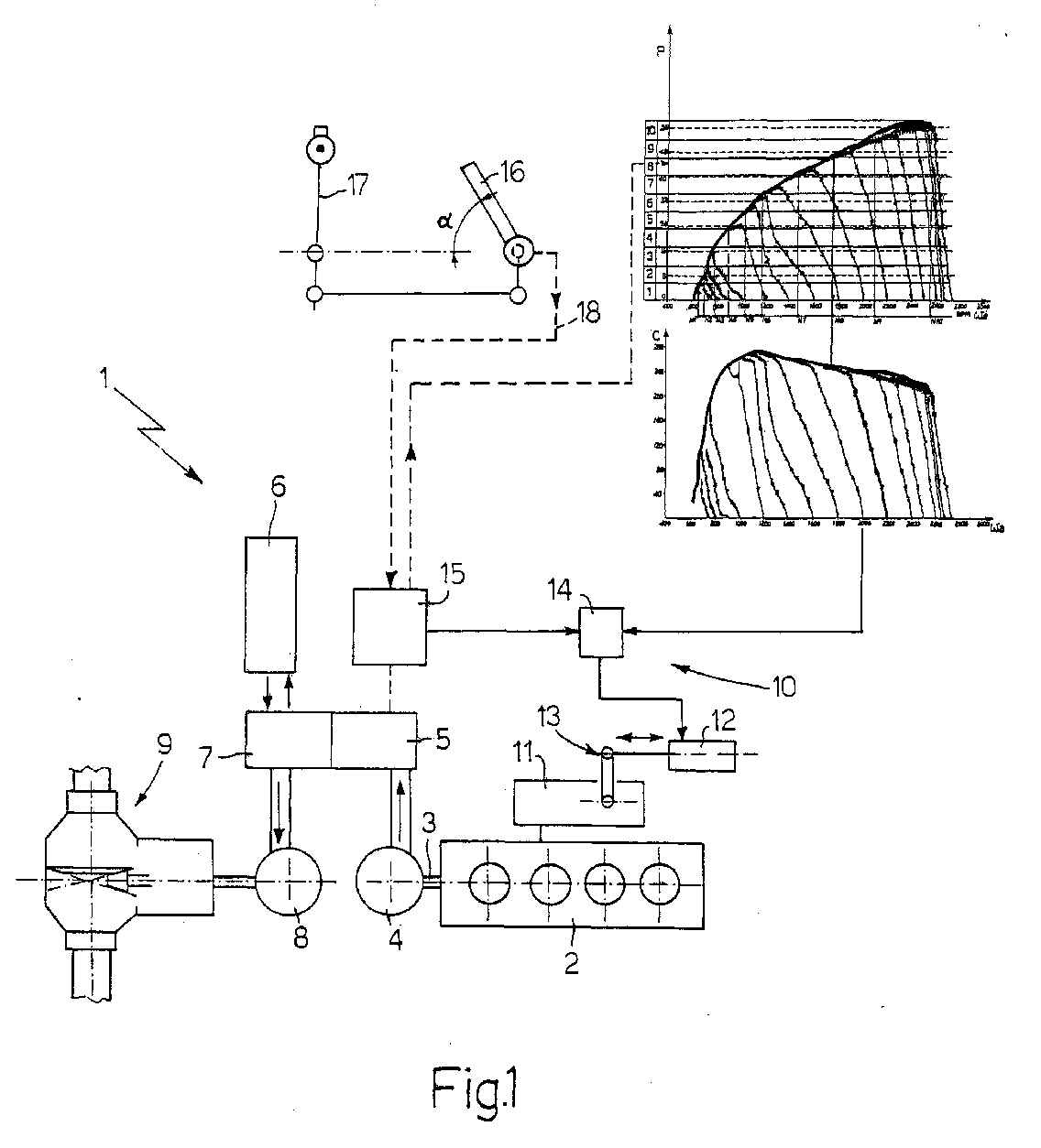
- Number 1 in Figure 1 indicates as a whole a hybrid power unit for implementing the method according to the present invention.
- Unit 1 in Figure 1 is a hybrid unit of which the components are arranged in series, but the teachings of the present invention may also be applied to advantage to any hybrid unit, in particular a parallel hybrid unit (not shown).
- Unit 1 comprises an internal combustion engine 2, in particular a diesel engine, which, by means of a drive shaft 3, drives a generator 4 connected electrically to a charge device 5 for charging an electric energy storage device 6.
- Charge device 5 and storage device 6 are connected electrically to a device 7 for controlling an electric motor 8 powering an axle 9 of a vehicle (not shown).
- Fuel injection into internal combustion engine 2 is controlled by an injection device 10 comprising an injection pump 11, controlled by an actuating cylinder 12 via a lever mechanism 13, and an electronic board 14 for controlling the commands from an electronic central control unit 15.
- the desired vehicle speed is entered by means of a pedal 16, or a hand lever 17 connected electrically in parallel with pedal 16.
- An electric line 18 connects pedal 16 and hand lever 17 to central control unit 15.
- the operator when selecting a given tilt angle ⁇ of pedal 16 or lever 17 (angle ⁇ in this case not shown) in actual fact merely selects the travelling speed of the vehicle.
- the electric signal generated by the operator at pedal 16 or lever 17 is transmitted to central control unit 15 for further processing to determine the state of device 10.
- FIG 1 also shows how central control unit 15 controls device 10 using the method according to the present invention, which is described in detail below with reference to Figures 2 and 3.
- Figure 2 shows a graph employed in the method according to the present invention, and which shows the variation in power P transmitted to output shaft 3 of engine 2 as a function of the rotational speed ⁇ a of shaft 3.
- a number of curves are depicted showing the relation between power P and rotational speed ⁇ a as a function of the injector opening of device 10, i.e. of injection pump 11.
- injector opening is intended to mean the injector opening directly proportional to the quantity of fuel injected into engine 2.
- Figure 2 shows sixteen curves corresponding to injector openings ranging between 100% and 10%. More specifically, Figure 2 shows sixteen injector opening curves q ranging from a curve q0 showing the operation of engine 2 with a 100% injector opening, i.e. with pump 11 fully open to inject the maximum amount of fuel into engine 2, to a curve q1 showing operation of engine 2 with a 10% injector opening of pump 11.
- Figure 2 also shows a curve q0' representing the envelope of the various opening curves q according to the maximum-opening curve q0.
- Figure 3 shows a graph employed in the method according to the present invention together with the Figure 2 graph, and which shows the variation in torque C transmitted by engine 2 to drive shaft 3 as a function of the rotational speed ⁇ a of shaft 3.
- sixteen curves Q corresponding to injector openings ranging between 100% and 10% are depicted.
- curves Q include a maximum, i.e. 100%, opening curve Q0; a 10% opening curve Q1; and a curve Q0' representing the envelope of the various opening curves Q according to curve Q0.
- Figure 2 and 3 graphs are supplied by the manufacturer of engine 2 and normally vary from one engine to another.
- the Figure 2 and 3 graphs relate to a given engine 2 with given construction characteristics, which, in this purely illustrative context, need not be dealt with in detail.
- the method according to the present invention employs:
- the method comprises the steps of:
- central control unit 15 can be calibrated accurately with no need for simulating engine 2 under load. Obviously, starting from the maximum idling speed on curve Q2, as load is applied to engine 2, rotational speed ⁇ a decreases according to curve Q2 until the maximum torque value C1 is reached, thus achieving a minimum rotational speed ⁇ a of shaft 3 and optimum operation of engine 2.
- the method according to the present invention may be said to substantially calibrate the opening of injection pump 12, so that, for a given power, the most favourable torque for the corresponding rotational speed of shaft 3 is achieved at all times to minimise consumption, noise level, etc.
Landscapes
- Engineering & Computer Science (AREA)
- Chemical & Material Sciences (AREA)
- Combustion & Propulsion (AREA)
- Mechanical Engineering (AREA)
- Transportation (AREA)
- General Engineering & Computer Science (AREA)
- Electrical Control Of Air Or Fuel Supplied To Internal-Combustion Engine (AREA)
- Control Of Vehicle Engines Or Engines For Specific Uses (AREA)
- Electrical Control Of Ignition Timing (AREA)
Abstract
Description
- a first graph showing the power transmitted by the engine as a function of the rotation speed of a drive shaft, and for different injector openings of a power-regulating injection device; and
- a second graph showing the torque transmitted by the drive shaft as a function of the rotation speed of the drive shaft, and for different injector openings of the power-regulating injection device.
- a first graph (Figure 2) showing the power P
transmitted by engine 2 (Figure 1) as a function of the
rotational speed ωa of
drive shaft 3, and this for different injector openings ofinjection device 10 regulating power P; and - a second graph (Figure 3) showing the torque C
transmitted by
drive shaft 3 as a function of the rotational speed ωa ofdrive shaft 3, and for different injector openings of power-regulatinginjection device 10.
Claims (7)
- A method of regulating and controlling an internal combustion engine (2) forming part of a hybrid power unit (1) of a self-propelled vehicle, the method employing:the method comprising the steps of:a first graph showing the power (P) transmitted by the engine (2) as a function of the rotational speed (ωa) of a drive shaft (3), and for different injector openings of a power-regulating injection device (10); anda second graph showing the torque (C) transmitted by the drive shaft (3) as a function of the rotational speed (ωa) of the drive shaft (3), and for different injector openings of the power-regulating injection device (10); and(a) - dividing the y-axis of the first graph arbitrarily into a number of ranges (I1-I10) not necessarily of the same size;(b) - inserting on the y-axis of said first graph the power value (P1) required to operate the self-propelled vehicle, so as to single out a particular range (I8) comprising said power value (P1);(c) - locating on the first graph the maximum power value (P2) in the range (I8) singled out at step (b) and located on a curve (q0') corresponding to the maximum injector opening of an injection pump (11) forming part of said power-regulating injection device (10);(d) - determining on the first graph the rotational speed (ωa) of the drive shaft (3) corresponding to the maximum power value (P2) determined at step (c);(e) - transferring the rotational speed (ωa) determined at step (d) to said second graph to locate the corresponding torque value (C1); said value being located at the point of intersection (P3) between the maximum injector opening torque curve (Q0') and a vertical line through said rotational speed (ωa);(f) - locating on the second graph the partial-torque and relative injector opening curve (Q2) through the point (P3) corresponding to the rotational speed (ωa) and torque value (C1) determined at steps (d) and (e);(g) - tracing on the second graph the partial-torque curve (Q2) corresponding to said torque value (C1) up to the intersection with the x-axis to determine the idling speed (ω20) of the engine at the given injector opening; and(h) - determining experimentally the position of an external actuator (12) for regulating said injection pump (11), so that said pump (11) is regulated to inject fuel into the engine (2) according to the injector opening determined at step (f).
- A method according to claim 1, characterized in that said ranges (I1-I10) of step (a) are equal in size.
- A method according to claim 1 or 2, characterized in that it is controlled by an electronic central control unit (15).
- A hybrid power unit (1), characterized in that it comprises means for implementing the method according to claims 1 to 3.
- A hybrid power unit (1) according to claim 4, characterized in that it comprises a diesel engine (2).
- A hybrid power unit (1) according to claim 4 or 5, characterized in that the unit is a series type hybrid unit.
- A hybrid power unit (1) according to claim 4 or 5, characterized in that the unit is a parallel type hybrid unit.
Applications Claiming Priority (3)
| Application Number | Priority Date | Filing Date | Title |
|---|---|---|---|
| IT2000BO000661A ITBO20000661A1 (en) | 2000-11-14 | 2000-11-14 | ADJUSTMENT AND CONTROL METHOD OF AN INTERNAL COMBUSTION ENGINE |
| ITBO000661 | 2000-11-14 | ||
| US10/026,267 US6578549B1 (en) | 2000-11-14 | 2001-12-21 | Method of regulating and controlling an internal combustion engine |
Publications (3)
| Publication Number | Publication Date |
|---|---|
| EP1223066A2 true EP1223066A2 (en) | 2002-07-17 |
| EP1223066A3 EP1223066A3 (en) | 2004-05-19 |
| EP1223066B1 EP1223066B1 (en) | 2006-04-26 |
Family
ID=29272075
Family Applications (1)
| Application Number | Title | Priority Date | Filing Date |
|---|---|---|---|
| EP01204265A Expired - Lifetime EP1223066B1 (en) | 2000-11-14 | 2001-11-07 | Method of regulating and controlling an internal combustion engine |
Country Status (3)
| Country | Link |
|---|---|
| US (1) | US6578549B1 (en) |
| EP (1) | EP1223066B1 (en) |
| IT (1) | ITBO20000661A1 (en) |
Cited By (5)
| Publication number | Priority date | Publication date | Assignee | Title |
|---|---|---|---|---|
| US7364409B2 (en) | 2004-02-11 | 2008-04-29 | Haldex Hydraulics Corporation | Piston assembly for rotary hydraulic machines |
| US7380490B2 (en) | 2004-02-11 | 2008-06-03 | Haldex Hydraulics Corporation | Housing for rotary hydraulic machines |
| US7402027B2 (en) | 2004-02-11 | 2008-07-22 | Haldex Hydraulics Corporation | Rotating group of a hydraulic machine |
| US7516613B2 (en) | 2004-12-01 | 2009-04-14 | Haldex Hydraulics Corporation | Hydraulic drive system |
| US7992484B2 (en) | 2004-02-11 | 2011-08-09 | Haldex Hydraulics Corporation | Rotary hydraulic machine and controls |
Families Citing this family (1)
| Publication number | Priority date | Publication date | Assignee | Title |
|---|---|---|---|---|
| US20090274226A1 (en) * | 2008-05-05 | 2009-11-05 | Motorola, Inc. | Sounding channel based feedback in a wireless communication system |
Family Cites Families (4)
| Publication number | Priority date | Publication date | Assignee | Title |
|---|---|---|---|---|
| US4566068A (en) * | 1981-11-26 | 1986-01-21 | Diesel Kiki Co., Ltd. | Characteristic signal generator for an electronically controlled fuel injection pump |
| DE4205770C2 (en) * | 1992-02-21 | 1994-05-05 | Mannesmann Ag | Vehicle with internal combustion engine, electric generator and electric motor |
| US6089082A (en) * | 1998-12-07 | 2000-07-18 | Ford Global Technologies, Inc. | Air estimation system and method |
| US6263858B1 (en) * | 2000-01-20 | 2001-07-24 | Ford Global Technologies, Inc. | Powertrain output monitor |
-
2000
- 2000-11-14 IT IT2000BO000661A patent/ITBO20000661A1/en unknown
-
2001
- 2001-11-07 EP EP01204265A patent/EP1223066B1/en not_active Expired - Lifetime
- 2001-12-21 US US10/026,267 patent/US6578549B1/en not_active Expired - Lifetime
Cited By (9)
| Publication number | Priority date | Publication date | Assignee | Title |
|---|---|---|---|---|
| US7364409B2 (en) | 2004-02-11 | 2008-04-29 | Haldex Hydraulics Corporation | Piston assembly for rotary hydraulic machines |
| US7380490B2 (en) | 2004-02-11 | 2008-06-03 | Haldex Hydraulics Corporation | Housing for rotary hydraulic machines |
| US7402027B2 (en) | 2004-02-11 | 2008-07-22 | Haldex Hydraulics Corporation | Rotating group of a hydraulic machine |
| US7992484B2 (en) | 2004-02-11 | 2011-08-09 | Haldex Hydraulics Corporation | Rotary hydraulic machine and controls |
| US9115770B2 (en) | 2004-02-11 | 2015-08-25 | Concentric Rockford Inc. | Rotary hydraulic machine and controls |
| US7516613B2 (en) | 2004-12-01 | 2009-04-14 | Haldex Hydraulics Corporation | Hydraulic drive system |
| US7856817B2 (en) | 2004-12-01 | 2010-12-28 | Haldex Hydraulics Corporation | Hydraulic drive system |
| US8196397B2 (en) | 2004-12-01 | 2012-06-12 | Concentric Rockford, Inc. | Hydraulic drive system |
| US8596055B2 (en) | 2004-12-01 | 2013-12-03 | Concentric Rockford Inc. | Hydraulic drive system |
Also Published As
| Publication number | Publication date |
|---|---|
| EP1223066A3 (en) | 2004-05-19 |
| US6578549B1 (en) | 2003-06-17 |
| ITBO20000661A1 (en) | 2002-05-14 |
| ITBO20000661A0 (en) | 2000-11-14 |
| EP1223066B1 (en) | 2006-04-26 |
| US20030116128A1 (en) | 2003-06-26 |
Similar Documents
| Publication | Publication Date | Title |
|---|---|---|
| EP0287670B1 (en) | Driving control apparatus for hydraulic construction machines | |
| CN101900043B (en) | Control device of engine, control device of engine and hydraulic pump, and control device of engine, hydraulic pump, and generator motor | |
| US5484351A (en) | Arrangement for controlling the torque to be supplied by a drive unit of a motor vehicle | |
| JP4242406B2 (en) | Throttle control response selection method | |
| US6328671B1 (en) | Drive force control device | |
| RU2491180C2 (en) | Working machine with torque limitation for infinitely variable speed transmission | |
| WO2008057177A2 (en) | Method and system for controlling machine power | |
| EP0922600A2 (en) | Drive control system for hybrid vehicle with engine start-up mode | |
| CN101994583A (en) | Active coast and cruise control system and methods | |
| US20090082945A1 (en) | Continuously variable transmission system with power boost | |
| CN101861455A (en) | Engine control device | |
| JP2013538310A (en) | Control system with load adjustable economy mode | |
| US6772060B2 (en) | Electronic engine control and method | |
| US7472008B2 (en) | Systems and methods for controlling mobile machine power | |
| EP0265526B1 (en) | Apparatus for controlling the engine of wheeled construction machine | |
| EP1223066B1 (en) | Method of regulating and controlling an internal combustion engine | |
| CN101523033B (en) | Control device for internal combustion engine | |
| US20050107209A1 (en) | Device for controlling the torque of the drive unit of a vehicle | |
| JP4819782B2 (en) | Internal combustion engine speed control device for work machine | |
| KR100398219B1 (en) | Method for emission controlling of diesel engine in vehicle | |
| JPH0874643A (en) | Fuel control device for diesel engine | |
| US6442471B1 (en) | Drive train control of a vehicle having continuously variable transmission | |
| JP2002295286A (en) | Farm work machine | |
| JPH08261035A (en) | Fuel control device for diesel engine | |
| SU1257263A1 (en) | Method of control of tractor-mounted engine/transmission unit |
Legal Events
| Date | Code | Title | Description |
|---|---|---|---|
| PUAI | Public reference made under article 153(3) epc to a published international application that has entered the european phase |
Free format text: ORIGINAL CODE: 0009012 |
|
| AK | Designated contracting states |
Kind code of ref document: A2 Designated state(s): AT BE CH CY DE DK ES FI FR GB GR IE IT LI LU MC NL PT SE TR |
|
| AX | Request for extension of the european patent |
Free format text: AL;LT;LV;MK;RO;SI |
|
| RAP1 | Party data changed (applicant data changed or rights of an application transferred) |
Owner name: CNH ITALIA S.P.A. |
|
| PUAL | Search report despatched |
Free format text: ORIGINAL CODE: 0009013 |
|
| AK | Designated contracting states |
Kind code of ref document: A3 Designated state(s): AT BE CH CY DE DK ES FI FR GB GR IE IT LI LU MC NL PT SE TR |
|
| AX | Request for extension of the european patent |
Extension state: AL LT LV MK RO SI |
|
| RIC1 | Information provided on ipc code assigned before grant |
Ipc: 7B 60K 6/04 A Ipc: 7F 02D 41/30 B |
|
| 17P | Request for examination filed |
Effective date: 20041025 |
|
| AKX | Designation fees paid |
Designated state(s): AT BE CH CY DE DK ES FI FR GB GR IE IT LI LU MC NL PT SE TR |
|
| 17Q | First examination report despatched |
Effective date: 20050124 |
|
| GRAP | Despatch of communication of intention to grant a patent |
Free format text: ORIGINAL CODE: EPIDOSNIGR1 |
|
| GRAS | Grant fee paid |
Free format text: ORIGINAL CODE: EPIDOSNIGR3 |
|
| GRAA | (expected) grant |
Free format text: ORIGINAL CODE: 0009210 |
|
| AK | Designated contracting states |
Kind code of ref document: B1 Designated state(s): AT BE CH CY DE DK ES FI FR GB GR IE IT LI LU MC NL PT SE TR |
|
| PG25 | Lapsed in a contracting state [announced via postgrant information from national office to epo] |
Ref country code: IT Free format text: LAPSE BECAUSE OF FAILURE TO SUBMIT A TRANSLATION OF THE DESCRIPTION OR TO PAY THE FEE WITHIN THE PRESCRIBED TIME-LIMIT;WARNING: LAPSES OF ITALIAN PATENTS WITH EFFECTIVE DATE BEFORE 2007 MAY HAVE OCCURRED AT ANY TIME BEFORE 2007. THE CORRECT EFFECTIVE DATE MAY BE DIFFERENT FROM THE ONE RECORDED. Effective date: 20060426 Ref country code: CH Free format text: LAPSE BECAUSE OF FAILURE TO SUBMIT A TRANSLATION OF THE DESCRIPTION OR TO PAY THE FEE WITHIN THE PRESCRIBED TIME-LIMIT Effective date: 20060426 Ref country code: AT Free format text: LAPSE BECAUSE OF FAILURE TO SUBMIT A TRANSLATION OF THE DESCRIPTION OR TO PAY THE FEE WITHIN THE PRESCRIBED TIME-LIMIT Effective date: 20060426 Ref country code: FI Free format text: LAPSE BECAUSE OF FAILURE TO SUBMIT A TRANSLATION OF THE DESCRIPTION OR TO PAY THE FEE WITHIN THE PRESCRIBED TIME-LIMIT Effective date: 20060426 Ref country code: BE Free format text: LAPSE BECAUSE OF FAILURE TO SUBMIT A TRANSLATION OF THE DESCRIPTION OR TO PAY THE FEE WITHIN THE PRESCRIBED TIME-LIMIT Effective date: 20060426 Ref country code: NL Free format text: LAPSE BECAUSE OF FAILURE TO SUBMIT A TRANSLATION OF THE DESCRIPTION OR TO PAY THE FEE WITHIN THE PRESCRIBED TIME-LIMIT Effective date: 20060426 Ref country code: LI Free format text: LAPSE BECAUSE OF FAILURE TO SUBMIT A TRANSLATION OF THE DESCRIPTION OR TO PAY THE FEE WITHIN THE PRESCRIBED TIME-LIMIT Effective date: 20060426 |
|
| REG | Reference to a national code |
Ref country code: GB Ref legal event code: FG4D |
|
| REG | Reference to a national code |
Ref country code: IE Ref legal event code: FG4D |
|
| REF | Corresponds to: |
Ref document number: 60119074 Country of ref document: DE Date of ref document: 20060601 Kind code of ref document: P |
|
| PG25 | Lapsed in a contracting state [announced via postgrant information from national office to epo] |
Ref country code: SE Free format text: LAPSE BECAUSE OF FAILURE TO SUBMIT A TRANSLATION OF THE DESCRIPTION OR TO PAY THE FEE WITHIN THE PRESCRIBED TIME-LIMIT Effective date: 20060726 Ref country code: DK Free format text: LAPSE BECAUSE OF FAILURE TO SUBMIT A TRANSLATION OF THE DESCRIPTION OR TO PAY THE FEE WITHIN THE PRESCRIBED TIME-LIMIT Effective date: 20060726 |
|
| PG25 | Lapsed in a contracting state [announced via postgrant information from national office to epo] |
Ref country code: ES Free format text: LAPSE BECAUSE OF FAILURE TO SUBMIT A TRANSLATION OF THE DESCRIPTION OR TO PAY THE FEE WITHIN THE PRESCRIBED TIME-LIMIT Effective date: 20060806 |
|
| PG25 | Lapsed in a contracting state [announced via postgrant information from national office to epo] |
Ref country code: PT Free format text: LAPSE BECAUSE OF FAILURE TO SUBMIT A TRANSLATION OF THE DESCRIPTION OR TO PAY THE FEE WITHIN THE PRESCRIBED TIME-LIMIT Effective date: 20060926 |
|
| ET | Fr: translation filed | ||
| REG | Reference to a national code |
Ref country code: CH Ref legal event code: PL |
|
| NLV1 | Nl: lapsed or annulled due to failure to fulfill the requirements of art. 29p and 29m of the patents act | ||
| PG25 | Lapsed in a contracting state [announced via postgrant information from national office to epo] |
Ref country code: IE Free format text: LAPSE BECAUSE OF NON-PAYMENT OF DUE FEES Effective date: 20061107 |
|
| PG25 | Lapsed in a contracting state [announced via postgrant information from national office to epo] |
Ref country code: MC Free format text: LAPSE BECAUSE OF NON-PAYMENT OF DUE FEES Effective date: 20061130 |
|
| PLBE | No opposition filed within time limit |
Free format text: ORIGINAL CODE: 0009261 |
|
| STAA | Information on the status of an ep patent application or granted ep patent |
Free format text: STATUS: NO OPPOSITION FILED WITHIN TIME LIMIT |
|
| 26N | No opposition filed |
Effective date: 20070129 |
|
| PG25 | Lapsed in a contracting state [announced via postgrant information from national office to epo] |
Ref country code: GR Free format text: LAPSE BECAUSE OF FAILURE TO SUBMIT A TRANSLATION OF THE DESCRIPTION OR TO PAY THE FEE WITHIN THE PRESCRIBED TIME-LIMIT Effective date: 20060727 |
|
| PG25 | Lapsed in a contracting state [announced via postgrant information from national office to epo] |
Ref country code: TR Free format text: LAPSE BECAUSE OF FAILURE TO SUBMIT A TRANSLATION OF THE DESCRIPTION OR TO PAY THE FEE WITHIN THE PRESCRIBED TIME-LIMIT Effective date: 20060426 Ref country code: LU Free format text: LAPSE BECAUSE OF NON-PAYMENT OF DUE FEES Effective date: 20061107 |
|
| PG25 | Lapsed in a contracting state [announced via postgrant information from national office to epo] |
Ref country code: CY Free format text: LAPSE BECAUSE OF FAILURE TO SUBMIT A TRANSLATION OF THE DESCRIPTION OR TO PAY THE FEE WITHIN THE PRESCRIBED TIME-LIMIT Effective date: 20060426 |
|
| REG | Reference to a national code |
Ref country code: DE Ref legal event code: R079 Ref document number: 60119074 Country of ref document: DE Free format text: PREVIOUS MAIN CLASS: B60K0006040000 Ipc: B60K0006000000 Ref country code: DE Ref legal event code: R082 Ref document number: 60119074 Country of ref document: DE Representative=s name: PATENTANWAELTE WALLACH, KOCH & PARTNER, DE |
|
| REG | Reference to a national code |
Ref country code: DE Ref legal event code: R082 Ref document number: 60119074 Country of ref document: DE Representative=s name: PATENTANWAELTE WALLACH, KOCH & PARTNER, DE Effective date: 20140623 Ref country code: DE Ref legal event code: R081 Ref document number: 60119074 Country of ref document: DE Owner name: CNH INDUSTRIAL ITALIA S.P.A., IT Free format text: FORMER OWNER: CNH ITALIA S.P.A., MODENA, IT Effective date: 20140623 Ref country code: DE Ref legal event code: R079 Ref document number: 60119074 Country of ref document: DE Free format text: PREVIOUS MAIN CLASS: B60K0006040000 Ipc: B60K0006000000 Effective date: 20140623 Ref country code: DE Ref legal event code: R082 Ref document number: 60119074 Country of ref document: DE Representative=s name: PATENTANWAELTE WALLACH, KOCH, DR. HAIBACH, FEL, DE Effective date: 20140623 |
|
| REG | Reference to a national code |
Ref country code: FR Ref legal event code: CD Owner name: CNH INDUSTRIAL ITALIA S.P.A. Effective date: 20150313 |
|
| REG | Reference to a national code |
Ref country code: FR Ref legal event code: PLFP Year of fee payment: 15 |
|
| REG | Reference to a national code |
Ref country code: FR Ref legal event code: PLFP Year of fee payment: 16 |
|
| REG | Reference to a national code |
Ref country code: FR Ref legal event code: PLFP Year of fee payment: 17 |
|
| PGFP | Annual fee paid to national office [announced via postgrant information from national office to epo] |
Ref country code: DE Payment date: 20171011 Year of fee payment: 17 |
|
| PGFP | Annual fee paid to national office [announced via postgrant information from national office to epo] |
Ref country code: GB Payment date: 20171006 Year of fee payment: 17 Ref country code: IT Payment date: 20171110 Year of fee payment: 17 |
|
| REG | Reference to a national code |
Ref country code: FR Ref legal event code: PLFP Year of fee payment: 18 |
|
| REG | Reference to a national code |
Ref country code: DE Ref legal event code: R119 Ref document number: 60119074 Country of ref document: DE |
|
| GBPC | Gb: european patent ceased through non-payment of renewal fee |
Effective date: 20181107 |
|
| PG25 | Lapsed in a contracting state [announced via postgrant information from national office to epo] |
Ref country code: DE Free format text: LAPSE BECAUSE OF NON-PAYMENT OF DUE FEES Effective date: 20190601 Ref country code: IT Free format text: LAPSE BECAUSE OF NON-PAYMENT OF DUE FEES Effective date: 20181107 |
|
| PG25 | Lapsed in a contracting state [announced via postgrant information from national office to epo] |
Ref country code: GB Free format text: LAPSE BECAUSE OF NON-PAYMENT OF DUE FEES Effective date: 20181107 |
|
| PGFP | Annual fee paid to national office [announced via postgrant information from national office to epo] |
Ref country code: FR Payment date: 20191124 Year of fee payment: 19 |
|
| PG25 | Lapsed in a contracting state [announced via postgrant information from national office to epo] |
Ref country code: FR Free format text: LAPSE BECAUSE OF NON-PAYMENT OF DUE FEES Effective date: 20201130 |