EP1222899A2 - Pedicle screw assembly - Google Patents
Pedicle screw assembly Download PDFInfo
- Publication number
- EP1222899A2 EP1222899A2 EP01402612A EP01402612A EP1222899A2 EP 1222899 A2 EP1222899 A2 EP 1222899A2 EP 01402612 A EP01402612 A EP 01402612A EP 01402612 A EP01402612 A EP 01402612A EP 1222899 A2 EP1222899 A2 EP 1222899A2
- Authority
- EP
- European Patent Office
- Prior art keywords
- coupling element
- fastener
- head
- assembly
- radial surface
- Prior art date
- Legal status (The legal status is an assumption and is not a legal conclusion. Google has not performed a legal analysis and makes no representation as to the accuracy of the status listed.)
- Granted
Links
Images


Classifications
-
- A—HUMAN NECESSITIES
- A61—MEDICAL OR VETERINARY SCIENCE; HYGIENE
- A61B—DIAGNOSIS; SURGERY; IDENTIFICATION
- A61B17/00—Surgical instruments, devices or methods
- A61B17/56—Surgical instruments or methods for treatment of bones or joints; Devices specially adapted therefor
- A61B17/58—Surgical instruments or methods for treatment of bones or joints; Devices specially adapted therefor for osteosynthesis, e.g. bone plates, screws or setting implements
- A61B17/68—Internal fixation devices, including fasteners and spinal fixators, even if a part thereof projects from the skin
- A61B17/70—Spinal positioners or stabilisers, e.g. stabilisers comprising fluid filler in an implant
- A61B17/7001—Screws or hooks combined with longitudinal elements which do not contact vertebrae
- A61B17/7035—Screws or hooks, wherein a rod-clamping part and a bone-anchoring part can pivot relative to each other
- A61B17/7037—Screws or hooks, wherein a rod-clamping part and a bone-anchoring part can pivot relative to each other wherein pivoting is blocked when the rod is clamped
-
- G—PHYSICS
- G06—COMPUTING; CALCULATING OR COUNTING
- G06Q—INFORMATION AND COMMUNICATION TECHNOLOGY [ICT] SPECIALLY ADAPTED FOR ADMINISTRATIVE, COMMERCIAL, FINANCIAL, MANAGERIAL OR SUPERVISORY PURPOSES; SYSTEMS OR METHODS SPECIALLY ADAPTED FOR ADMINISTRATIVE, COMMERCIAL, FINANCIAL, MANAGERIAL OR SUPERVISORY PURPOSES, NOT OTHERWISE PROVIDED FOR
- G06Q10/00—Administration; Management
- G06Q10/10—Office automation; Time management
- G06Q10/107—Computer-aided management of electronic mailing [e-mailing]
-
- A—HUMAN NECESSITIES
- A61—MEDICAL OR VETERINARY SCIENCE; HYGIENE
- A61B—DIAGNOSIS; SURGERY; IDENTIFICATION
- A61B17/00—Surgical instruments, devices or methods
- A61B17/56—Surgical instruments or methods for treatment of bones or joints; Devices specially adapted therefor
- A61B17/58—Surgical instruments or methods for treatment of bones or joints; Devices specially adapted therefor for osteosynthesis, e.g. bone plates, screws or setting implements
- A61B17/68—Internal fixation devices, including fasteners and spinal fixators, even if a part thereof projects from the skin
- A61B17/70—Spinal positioners or stabilisers, e.g. stabilisers comprising fluid filler in an implant
- A61B17/7001—Screws or hooks combined with longitudinal elements which do not contact vertebrae
- A61B17/7032—Screws or hooks with U-shaped head or back through which longitudinal rods pass
-
- A—HUMAN NECESSITIES
- A61—MEDICAL OR VETERINARY SCIENCE; HYGIENE
- A61B—DIAGNOSIS; SURGERY; IDENTIFICATION
- A61B17/00—Surgical instruments, devices or methods
- A61B17/56—Surgical instruments or methods for treatment of bones or joints; Devices specially adapted therefor
- A61B17/58—Surgical instruments or methods for treatment of bones or joints; Devices specially adapted therefor for osteosynthesis, e.g. bone plates, screws or setting implements
- A61B17/68—Internal fixation devices, including fasteners and spinal fixators, even if a part thereof projects from the skin
- A61B17/70—Spinal positioners or stabilisers, e.g. stabilisers comprising fluid filler in an implant
- A61B17/7074—Tools specially adapted for spinal fixation operations other than for bone removal or filler handling
- A61B17/7076—Tools specially adapted for spinal fixation operations other than for bone removal or filler handling for driving, positioning or assembling spinal clamps or bone anchors specially adapted for spinal fixation
- A61B17/7082—Tools specially adapted for spinal fixation operations other than for bone removal or filler handling for driving, positioning or assembling spinal clamps or bone anchors specially adapted for spinal fixation for driving, i.e. rotating, screws or screw parts specially adapted for spinal fixation, e.g. for driving polyaxial or tulip-headed screws
-
- A—HUMAN NECESSITIES
- A61—MEDICAL OR VETERINARY SCIENCE; HYGIENE
- A61B—DIAGNOSIS; SURGERY; IDENTIFICATION
- A61B17/00—Surgical instruments, devices or methods
- A61B17/56—Surgical instruments or methods for treatment of bones or joints; Devices specially adapted therefor
- A61B2017/564—Methods for bone or joint treatment
Definitions
- the present invention relates generally to spinal fixation devices and more specifically relates to a pedicle screw assembly having a low profile and having an improved screwhead/coupling element interface for locking the assembly.
- the spinal column is a highly complex system of bones and connective tissues that provides support for the body and protects the delicate spinal cord and nerves.
- the spinal column includes a series of vertebrae stacked one atop the other, each vertebral body including an inner or central portion of relatively weak cancellous bone and an outer portion of relatively strong cortical bone. Situated between each vertebral body is an intervertebral disc that cushions and dampens compressive forces experienced by to the spinal column.
- a vertebral canal containing the spinal cord and nerves is located behind the vertebral bodies.
- spinal column disorders including scoliosis (abnormal lateral curvature of the spine), kyphosis (abnormal forward curvature of the spine, usually in the thoracic spine), excess lordosis (abnormal backward curvature of the spine, usually in the lumbar spine), spondylolisthesis (forward displacement of one vertebra over another, usually in a lumbar or cervical spine) and other disorders caused by abnormalities, disease or trauma, such as ruptured or slipped discs, degenerative disc disease, fractured vertebra, and the like. Patients that suffer from such conditions usually experience extreme and debilitating pain, as well as diminished nerve function.
- the present invention generally involves a technique commonly referred to as spinal fixation whereby surgical implants are used for fusing together and/or mechanically immobilizing vertebrae of the spine.
- Spinal fixation may also be used to alter the alignment of adjacent vertebrae relative to one another so as to change the overall alignment of the spine.
- Such techniques have been used effectively to treat the above-described conditions and, in most cases, to relieve pain suffered by the patient.
- One spinal fixation technique involves immobilizing the spine by using orthopedic rods, commonly referred to as spine rods, that run generally parallel to the spine. This may be accomplished by exposing the spine posteriorly and fastening bone screws to the pedicles of the appropriate vertebrae.
- the pedicle screws are generally placed two per vertebra and serve as anchor points for the spine rods.
- Clamping elements adapted for receiving a spine rod therethrough are then used to join the spine rods to the screws.
- the aligning influence of the rods forces the spine to conform to a more desirable shape.
- the spine rods may be bent to achieve the desired curvature of the spinal column.
- U.S. Patent 5,129,388 to Vignaud et al. discloses a spinal fixation device including a pedicle screw having a U-shaped head rigidly connected to an upper end of the screw.
- the U-shaped head includes two arms forming a U-shaped channel for receiving a spine rod therein.
- the U-shaped head is internally threaded so that a set screw having external threads may be screwed therein.
- the fixation device also includes a cap covering an upper portion of the U-shaped head to prevent the arms from spreading upon threading the set screw into the internal threads of U-shaped head.
- U.S. Patent 5,733,286 to Errico et al. disclose polyaxial spinal fixation devices wherein the anchoring element fixed to the bone has a spherically-shaped head.
- the fixation devices in the above-identified patents also have orthopedic rod capturing assemblies for securing orthopedic rods in the capturing assemblies and connecting the rods with the anchoring elements.
- the spherically shaped heads of the anchoring elements permit movement of the anchoring elements relative to the orthopedic rod capturing assemblies.
- a pedicle screw assembly in certain preferred embodiments of commonly assigned U.S. Patent Application 09/414,272, filed October 7, 1999, the disclosure of which is hereby incorporated by reference as if fully set forth herein, includes a fastener having a tip end for insertion into bone and an expandable head at the opposite end of the fastener.
- the expandable head has an outer surface including a convex portion, a recess having an inner surface and defining an inner dimension, and at least one slot extending between the inner and outer surfaces thereof for allowing expansion of the head.
- the assembly also has an insert which can be positioned at least partially in the recess, the insert having an outer surface and defining an outer dimension that is greater than the inner dimension of the recess.
- the assembly includes a coupling element having a rod receiving opening, a bore for receiving the fastener, and a seat for receiving the head of the fastener, the seat including a concave portion for receiving the convex underside of the head and allowing the fastener to pivot and rotate relative to the coupling element before being locked therein.
- a locking element associated with the coupling element locks the orthopedic rod in the rod-receiving opening.
- the locking element is adapted to be forced against an orthopedic rod arranged in the rod receiving opening, to in turn force the insert into the recess of the expandable head so that the outer dimension of the insert bears against the inner dimension of the head, thereby expanding the outer surface of the head against the concave seat of the coupling element for locking the fastener from further pivotal movement relative to the coupling element.
- the head is expandable by virtue of the material of which it is made such as carbon fiber.
- a stabilizing assembly used for stabilizing a spinal column includes a fastener having an upper end and a head at the upper end, and at least one anchoring element between the upper and lower ends thereof.
- the head of the fastener preferably includes a center, an underside including a first radial surface and a top side including a second radial surface, the first radial surface defining a first radius from the center of the head and the second radial surface defining a second radius from the center of the head, the first radius being greater than the second radius.
- utilizing a fastener head having a dual-radius outer surface will provide a stabilizing assembly having a lower overall silhouette, thereby enhancing the compactness of the assembly.
- the lower silhouette results, in part, from the lower height of the second radial surface at the top of the head.
- the pedicle screw assembly also preferably includes a coupling element that couples together the fastener and a stabilizing rod inserted into the coupling element.
- the coupling element desirably includes an upper end and a lower end, a rod receiving opening adapted to receive a stabilizing rod, a bore extending through the lower end of the coupling element for receiving the fastener, and a seat adjacent the lower end of the coupling element adapted to engage the first radial surface of the head when the fastener is positioned in the bore.
- the seat is a conical-shaped seat having side walls that taper inwardly toward the lower end of the coupling element.
- the rod-receiving opening begins at the upper end of the coupling element and extends toward the lower end of the coupling element, the lower end of the rod-receiving opening preferably terminating at U-shaped channels on opposite sides of the coupling element.
- the stabilizing assembly also preferably includes a locking element associated with the coupling element, the locking element being adapted to apply a force upon a stabilizing rod positioned in the rod receiving opening, whereby the stabilizing rod in turn applies a force upon the second radial surface of the head for forcing the first radial surface of the head against the conical-shaped seat for preventing further pivotal and rotational movement of the fastener and the coupling element relative to one another.
- the locking element may include a set screw having external threads for threadably engaging internal threads of the coupling element.
- the coupling element preferably includes external threads formed on an exterior surface of the coupling element and the locking element includes a nut having internal threads threadable onto the external threads of the coupling element.
- the fastener is a screw fastener having a longitudinal axis extending between the upper and lower ends thereof, and includes a screwhead having at least one groove extending from the top surface of the screwhead toward the underside of the screwhead, the at least one groove being adapted to receive a driver for inserting the fastener into bone.
- the at least one groove preferably extends in a direction substantially parallel to the longitudinal axis of the fastener.
- the at least one groove desirably includes a plurality of grooves that are equally spaced apart from one another about the head.
- the fastener also preferably includes a neck portion having a reduced diameter for facilitating pivotal movement of the coupling element and the fastener relative to one another.
- the neck of the fastener may also have a concave surface so as to broaden the pivotal range of the fastener relative to the coupling element.
- the fastener may be inserted into bone using a driver including a shaft having a lower end and a plurality of prongs extending from the lower end of the shaft.
- the prongs are preferably adapted for being inserted into the grooves of the head.
- the shaft of the driver may include external threads that adapted for engaging the internal threads of the coupling element.
- the coupling element is anchored in place by anchoring the screw fastener into bone, such as vertebral bone.
- a pilot hole may be formed in the bone before the fastener is anchored to the bone.
- a gap preferably remains between the lower end of the coupling element and the bone so that the coupling element is free to pivot and rotate relative to the fastener and bone. This pivoting and rotary action facilitates the positioning of an orthopedic stabilizing rod within the rod-receiving opening of the coupling element.
- the locking element i.e., an externally threaded set screw
- the underside of the set screw abuts the orthopedic rod to apply a downward force through the rod onto the second radial surface of the head.
- downward force means a force directed toward the lower end of the coupling element. The downward force applied to the second radial surface of the head forces the first radial surface of the head into the conical-shaped seat of the coupling element.
- the present invention provides for a more reliable spinal fixation device and overcomes the post-operative shifting problems seen in prior art devices.
- the pedicle screw assembly of the present invention has fewer parts. As a result, implantation operations are greatly simplified and the possibility of a component being dropped inside a patient's body greatly reduced.
- the fastener may have one or more holes therein for receiving bone graft material as disclosed in U.S. Patent 4,484,570 to Sutter .
- the fastener may include a hook-shaped anchoring element as disclosed in the above-mentioned U.S. Patent 5,476,464 to Metz-Stavenhagen .
- the fastener may also be a structure having barbs on an outer surface thereof, whereby the fastener is forced into bone and the barbs prevent the fastener from being withdrawn from the bone.
- the top surface of the fastener head may include a socket adapted to receive a driver, such as a screwdriver or a hexagonal wrench.
- a driver such as a screwdriver or a hexagonal wrench.
- the fastener is attached to bone by inserting the driver into the socket, and then turning the driver to rotate the fastener in either a clockwise or counterclockwise direction.
- the coupling element may also have one or more impressions or grooves formed therein for receiving a controlling device, such as a persuader instrument for seating the rod in the coupling element.
- a controlling device such as a persuader instrument for seating the rod in the coupling element.
- the impressions or grooves generally extend in a direction substantially perpendicular to the longitudinal axis of the coupling element.
- the groove or blind holes may be formed in the exterior surface of the coupling element.
- the interior surface of the coupling element at the lower end thereof preferably defines the seat adapted for engaging the first radial surface at the underside of the head and for allowing the head to pivot relative to the coupling element before being locked in place.
- the seat is preferably provided adjacent the lower end of the coupling element.
- the seat may define a conical shape or a convex shape.
- the seat is a conical-shaped seat.
- the walls of the conical-shaped seat preferably taper inwardly toward one another so that the diameter of the walls at the lower end thereof is less than the outer diameter of the head.
- a portion of the fastener is passed through the bore of the coupling element until the underside of head is positioned adjacent the conical-shaped seat of the coupling element.
- the coupling element remains free to pivot relative to the fastener.
- a gap preferably exists between the bottom of the coupling element and bone, the presence of the gap facilitating pivoting movement of the coupling element.
- the neck portion of the fastener preferably having a concave surface with a diameter less than the diameter of the threaded portion of the fastener, enables the coupling element to pivot through a broader range of angles relative to the fastener.
- a spine rod may be more easily positioned within the rod receiving opening of the coupling element.
- a locking element is threaded into the threads of the coupling element.
- the rod exerts a downward force onto the second radial surface of the head.
- the downward force applied to the second radial surface of the head forces the first radial surface of the head into the conical-shaped seat of the coupling element.
- Engagement of the first radial surface of the head with the conical-shaped seat locks the coupling element relative to the head, thereby preventing further pivotal and rotary movement of the coupling element.
- the likelihood of post-operative shifting and/or moving of the pedicle screw assembly is greatly reduced, thereby minimizing the occurrence of post-operative complications for spinal implant patients.
- the present invention also preferably includes a tool for securing or anchoring the fastener in bone.
- the tool is preferably a driver having a rotatable shaft and one or more prongs extending from an end of the shaft for engaging grooves in the head.
- the driver has one prong for each groove in the head of the fastener.
- the driver may also have external threads at a lower end of the shaft.
- the external threads are preferably adapted for engaging the internal threads of the coupling element when a fastener is being anchored to the bone.
- the engagement of the external threads of the driver and the internal threads of the coupling element generally stabilizes the assembly when the fastener is secured to bone. Specifically, the engagement of the threads prevents the coupling element from moving relative to the fastener when driving the fastener into bone, thereby simplifying installation of the fasteners.
- a coupling element for a stabilizing assembly desirably includes an upper end and a lower end, a rod receiving opening adapted to receive a stabilizing rod, a bore extending through the lower end of the coupling element for receiving a fastener having a head with a first radial surface of a first diameter, and a seat adjacent the lower end of the coupling element adapted to engage an underside of the head of the fastener.
- the coupling element preferably includes threads extending from the upper end toward the lower end of the coupling element, and an annular lip between the threads and the seat of the coupling element, whereby the annular lip has a second diameter that is less than the first diameter of the first radial surface of the head.
- a coupling element for a stabilizing assembly includes an upper end and a lower end remote therefrom, and a rod receiving opening adapted to receive a stabilizing rod.
- the coupling element preferably ahs an exterior surface and an interior surface defining a central bore extending through the lower end of the coupling element.
- a seat adjacent the lower end of the coupling element is desirably adapted to engage an underside of a head of the fastener, whereby the coupling element includes one or more cuts between the rod-receiving opening and the exterior surface thereof for minimizing the width of the coupling element.
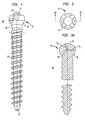
- a pedicle screw assembly includes a fastener 20, such as a screw fastener having a tip end 22 for insertion into bone and a head 24 at an upper end thereof.
- the screw fastener 20 preferably has external screw threads 26 that extend between the tip end 22 and screwhead 24.
- the screw threads 26 terminate at a neck 28 preferably located between screwhead 24 and an upper end of the screw threads 26.
- the neck 28 desirably has a concave surface having a diameter that is less than the diameter of the screw threads.
- the reduced diameter neck 28 allows the screw fastener 20 to pivot and rotate through a broader range of motion, as will be described in more detail below.
- the screw fastener, including the external threads 26, neck 28 and screwhead 24, are preferably made of a non-organic material that is durable and that can be implanted in a human body, such as titanium or stainless steel.
- screwhead 24 preferably has an underside 30 defining a first radial surface and a top side 32 defining a second radial surface.
- Screwhead 24 also desirably includes one or more grooves 34 that extend in a direction substantially parallel to the longitudinal axis of screw fastener 24.
- screwhead 24 includes a plurality of grooves 34 evenly spaced from one another and extending around the outer perimeter of screwhead 24.
- the top surface 32 screwhead 24 is preferably centered on the plurality of grooves 34.
- screwhead 24 includes a center 36, whereby the underside 30 of screwhead 24 defines the first radial surface having a radius R 1 from center 36.
- Screwhead 24 includes top surface 32 having second radial surface at a second radius R 2 from center 36.
- the plurality of grooves 34 are preferably adapted to receive prongs of a driver used to screw the screw fastener into bone, as will be described in more detail below.
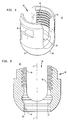
- pedicle screw assembly also includes a coupling element 40 for coupling an orthopedic stabilizing rod with the screw fastener shown in Figures 1-3B.
- Coupling element 40 is preferably made of an inert material such as titanium or stainless steel.
- Coupling element 40 has an upper end 42, a lower end 44, and a longitudinal axis C-C extending between the upper and lower ends.
- Coupling element 40 also preferably has an outer surface 46 including a convex surface at the lower end 44 thereof and a cylindrical surface at the upper end thereof.
- Outer surface 46 also preferably includes one or more grooves 48 formed therein so that coupling element 40 may be grasped and/or maneuvered using a securing element or tool, such as a persuader instrument used to seat the orthopedic rod in the pedicle screw assembly.
- the grooves 48 preferably extend in directions substantially perpendicular to the longitudinal axis C-C of coupling element 40.
- the coupling element 40 has a bore 50 for receiving the screw fastener the bore extending along the longitudinal axis C-C of coupling element 40.
- the bore 50 defines an inner surface of coupling element 40 and has internal threads 44 extending from the upper end 42 of the coupling element toward a cavity 52 adjacent lower end 44.
- the lower end of cavity 52 preferably has a conical shaped seat 54 including sidewalls tapering inwardly toward the lower end 44.
- the threads on the coupling element may be external threads.
- FIGs 6A and 6B show one preferred method for assembling screw fastener 20 with coupling element 40.
- tip end 22 of screw fastener 20 is passed through bore 50 of coupling element 40 from the upper end 42 toward the lower end 44 of the coupling element so that the threaded portion of screw fastener passes through bore 50.
- the threaded portion 26 of screw fastener 20 is able to pass freely through bore 50 because the threaded portion 26 has an outer diameter that is less than the internal diameter of the internal threads 44 of coupling element 40.
- screw fastener 20 continues to be inserted toward the lower end of coupling element 40 until screwhead 24 is disposed within cavity 52 of coupling element 40 and the underside of screwhead engages the seat of coupling element.
- neck 28 of screw fastener 20 is free to pivot and rotate relative to coupling element.
- neck 28 preferably has a reduced diameter and may also have a concave outer surface so that the screw fastener 20 and coupling element may pivot relative to one another over a broader range of angles.
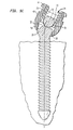
- the subassembly is ready to be inserted into bone 60.
- the screw fastener 20 may be anchored to bone 60 by drilling a pilot hole into the bone.
- the tip end (not shown) of screw fastener 20 may then be placed in the pilot hole and the screw fastener screwed into bone 60 using a driver or tool.
- One preferred driver 62 for driving screw fastener 20 into bone 60 includes a rotatable shaft 64 having a lower end 66 with a plurality of downwardly extending prongs 68.
- the prongs 68 are sized for fitting into the grooves 34 of the screwhead (not shown) of screw fastener 20.
- driver 62 may also include external threads 70, preferably between shaft 64 and prongs 68. External threads 70 are designed for threadably mating with the internal threads 44 of coupling element 40 (Figs. 4-5). The mating engagement of the external threads 70 of driver 62 and the internal threads 44 of coupling element 40 generally stabilizes the pedicle screw assembly when driving the screw fastener 20 into bone 60.
- coupling element 40 remains free to pivot and rotate relative to the screw fastener so that an orthopedic stabilizing rod 72 may be positioned within the rod receiving opening 74 of coupling element 40.
- Rod receiving opening 74 preferably includes a U-shaped opening extending from the top 42 of coupling element 40.
- the coupling element 40 may then be moved (e.g. pivoted) by engaging grooves 48 with a tool or by grasping the outer body portion of the coupling element. Coupling element 40 would then be pivoted and/or rotated so that an orthopedic rod 72 can be positioned in the rod receiving opening 74, as shown in Figure 9B.
- a set screw 76 having external threads (not shown) is screwed into the internal threads 44 of coupling element 40.
- Set screw 76 continues to be threaded into the internal threads 44 until an underside 78 of set screw 76 abuts against stabilizing rod 72.
- Set screw 76 is then further rotated into internal threads 44 for locking stabilizing rod 72 in rod receiving channel 74.
- the tightened set screw 76 applies a downward force through rod 72 onto the second radial surface at the top side 32 of screwhead 24.
- the downward force applied to the second radial surface of screwhead 24 forces the first radial surface at the underside 30 of screwhead 24 into the conical-shaped seat 54 of coupling element 40.
- Engagement of the first radial surface at the underside 30 of screwhead 24 with the conical-shaped seat 54 creates a spherical surface/conical surface friction lock that locks the coupling element 40 relative to the screwhead 24, thereby preventing further pivotal and rotary movement of coupling element 40 and screw fastener 20 relative to one another.
- the present invention is not limited by any particular theory of operation, it is believed that the engagement of the spherical surface of the screwhead with the conical seat of the coupling element dramatically improves the locking force exerted at the interface of the screwhead and the coupling element.
- a coupling element 140 for a stabilizing assembly includes an upper end 142 and a lower end 144.
- Coupling element 140 also includes an outer surface 146 extending between upper and lower ends 142, 144, the outer surface 146 including one or more grooves 148.
- Coupling element also includes a centrally located bore 150 extending between the upper end 142 and lower end 144 along longitudinal axis C-C. Bore 150 is surrounded by interior threads 151 extending from the upper end 142 toward the lower end 144.
- Coupling element 140 also includes a cavity 152 adjacent lower end 144, the cavity including a conical-shaped seat 154 having sidewalls that taper inwardly toward the lower end 144 of coupling element 140.
- Coupling element 140 also preferably includes an interior wall 153 having diameter D W between interior threads 151 and cavity 152, and a lip 155 between interior wall 153 and cavity 152.
- the lip 155 has a diameter D L that is less than the diameter D W of interior wall 153.
- the outer diameter D S of the first radial surface 130 of screwhead 124 is greater than the diameter D L of the lip 155 of coupling element.
- lip 155 serves as a detent that holds fastener 120 in the cavity 152 of coupling element 140 after the screwhead of fastener 120 has been assembled with the coupling element 140.
- FIG 11 shows a magnified view of a portion of the coupling element 140 shown in Figure 10.
- coupling element 140 includes bore 150 extending from an upper end (not shown) toward lower end 144 thereof, and an interior wall 153 extending between internal threads 151 and cavity 152.
- Cavity 152 includes conical-shaped seat 154 having inwardly tapering sidewalls 154.
- Coupling element 140 includes lip 155 positioned between interior wall 153 and cavity 152. Lip 155 has a diameter D L that is less than the diameter D W of the interior wall 153 of coupling element 140.
- Figure 12 shows screw fastener 120 having screwhead 124 at an upper end thereof, the screwhead including a first radial surface 130 at an underside thereof and a second radial surface 132 at a top side of screwhead 124.
- Screwhead 124 includes a center 136, a first radial surface 130 from center 136 having has a radius R 1 and a second radial surface 132 from center 136 having a second radius R 2 , whereby R 1 is greater than R 2 .
- the first radial surface of screwhead 124 defines an outer diameter D S that is two times the length of R 1 .
- FIGS 13A and 13B show screw fastener 120 being assembled with the coupling element 140 shown in Figures 10 and 11.
- coupling element 140 includes lip 155 having a diameter D L that is less than the diameter D S of the first radial surface 130 of screwhead 124, however, the outer diameter D S of the first radial surface 130 of screwhead 124 is less than the inner diameter of inner wall 153.
- the screw fastener 120 is passed through bore 150 so that screw threads 126 pass through the opening at lower end 144 of coupling element 140. Because the outer diameter D S of screwhead 124 is less than the inner diameter of inner wall 153, screwhead 124 passes easily through bore 150 until first radial surface 130 engages lip 155. Because the inner diameter D L of lip 155 is less than the outer diameter D S of the first radial surface 130 of screwhead 124, the lip 155 acts as a detent and the screwhead must be forced through the reduced diameter of lip 155.
- FIGS 14-16 show a coupling element 240 in accordance with further preferred embodiments of the present invention.
- Coupling element 240 includes upper end 242, lower end 244 and outer wall 246 extending between upper and lower ends 242, 244.
- the outer surface 246 of coupling element 240 includes grooves 248 on opposing arms thereof.
- Coupling element 240 has central bore 150 extending between upper and lower ends thereof.
- Coupling element 240 has a first arm 261A and a second arm 261B on either side of U-shaped rod-receiving opening 174, the U-shaped rod-receiving opening being adapted to receive a stabilizing rod (not shown).
- the edges of the U-shaped opening include cuts 263 formed therein.
- the cuts 263 reduce the profile or width of the coupling element, thereby minimizing interference with other coupling elements when a series of coupling elements are connected with a stabilizing rod.
- the cuts 263 allow the coupling elements 240 to be packed more tightly together and to be secured over each vertebrae, thereby improving fusion of a spinal segment.
- the present invention is not limited by any particular theory of operation, it has been observed that some patients have relatively small vertebrae, making it difficult to secure a coupling element over each vertebrae. As a result, some of the vertebrae may not have a section of the stabilizing assembly attached thereto, a situation that may adversely affect stabilization and fusion of a spine segment because the entire portion of the spine segment is not being stabilized.
- the cuts 263 minimize the occurrence of sharp edges on the coupling element that may irritate a patient's tissue or cut through a surgeon's surgical glove.
- FIG 17 shows a front elevation view of the coupling element 240 of Figures 14-16 assembled with screw fastener 220.
- Coupling element 240 includes internal threads 9not shown) for receiving set screw 276.
- Coupling element 240 includes cuts 263 for minimizing the profile of the coupling element and reducing the occurrence of sharp edges.
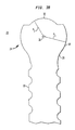
- FIG 18 shows a fastener 320 in accordance with another embodiment of the present invention.
- Fastener 320 includes head 324 having a first radial surface 330 having radius R 1 from center 336 and second radial surface 332 having radius R 2 from center 336. The first radius R 1 , is greater than the second radius R 2 .
- Fastener 320 includes hook 370 for securing the fastener to bond (not shown).
Landscapes
- Health & Medical Sciences (AREA)
- Engineering & Computer Science (AREA)
- Orthopedic Medicine & Surgery (AREA)
- Business, Economics & Management (AREA)
- Surgery (AREA)
- Life Sciences & Earth Sciences (AREA)
- Human Resources & Organizations (AREA)
- Neurology (AREA)
- Strategic Management (AREA)
- Entrepreneurship & Innovation (AREA)
- Heart & Thoracic Surgery (AREA)
- Animal Behavior & Ethology (AREA)
- General Health & Medical Sciences (AREA)
- Public Health (AREA)
- Veterinary Medicine (AREA)
- Molecular Biology (AREA)
- Medical Informatics (AREA)
- Biomedical Technology (AREA)
- Nuclear Medicine, Radiotherapy & Molecular Imaging (AREA)
- Computer Hardware Design (AREA)
- Data Mining & Analysis (AREA)
- Economics (AREA)
- Marketing (AREA)
- Operations Research (AREA)
- Quality & Reliability (AREA)
- Tourism & Hospitality (AREA)
- Physics & Mathematics (AREA)
- General Business, Economics & Management (AREA)
- General Physics & Mathematics (AREA)
- Theoretical Computer Science (AREA)
- Surgical Instruments (AREA)
- Medicines Containing Material From Animals Or Micro-Organisms (AREA)
Abstract
Description
Claims (45)
- A stabilizing assembly comprising:a fastener having an upper end and a lower end, a head at the upper end, and at least one anchoring element between the upper and lower ends thereof;said head including a center, an underside including a first radial surface and a top side including a second radial surface, wherein said first radial surface defines a first radius from the center of said head and said second radial surface defines a second radius from the center of said head, the first radius being greater than the second radius; anda coupling element having an upper end and a lower end, said coupling element including a rod receiving opening adapted to receive a stabilizing rod, a bore extending through the lower end of said coupling element for receiving said fastener, and a conical-shaped seat adjacent the lower end of said coupling element, wherein the first radial surface of said head is engagable with the conical-shaped seat when said fastener is positioned in the bore.
- The stabilizing assembly as claimed in claim 1, further comprising:a locking element associated with said coupling element to apply a force upon a stabilizing rod positioned in said rod receiving opening, wherein said stabilizing rod in turn applies a force upon the second radial surface of said head for forcing the first radial surface of said head against the conical-shaped seat for preventing further pivotal and rotational movement of said fastener and said coupling element relative to one another.
- The assembly as claimed in claim 1, wherein said fastener is a screw fastener, and wherein the at least one anchoring element comprises screw threads extending between the upper and lower ends thereof.
- The assembly as claimed in claim 1, wherein the at least one anchoring element comprises a hook at the lower end of said fastener.
- The assembly as claimed in claim 3, wherein said head includes at least one groove extending from the top surface toward the underside thereof, said at least one groove being adapted to receive a driver for inserting said fastener into bone.
- The assembly as claimed in claim 5, wherein said at least one groove extends in a direction substantially parallel to the longitudinal axis of said screw fastener.
- The assembly as claimed in claim 5, wherein said at least one groove includes a plurality of grooves.
- A driver for screwing the screw fastener of claim 7 into a bone, said driver comprising a shaft having a lower end and a plurality of prongs extending from the lower end of the shaft and insertable into said grooves of said screwhead.
- The driver as claimed in claim 8, wherein said driver includes external threads provided on the shaft.
- The driver as claimed in claim 9, wherein said coupling element includes internal threads, and wherein the external threads of said driver are engagable with the internal threads of said coupling element.
- The assembly as claimed in claim 1, wherein said coupling element includes internal threads extending from the upper end toward the lower end thereof, said coupling element including an annular lip having a diameter between the internal threads and the conical-shaped seat of the coupling element, and wherein the diameter of said annular lip is less than twice the first radius of said head.
- The assembly as claimed in claim 1, wherein the center of said screwhead is in substantial alignment with the longitudinal axis of said screw fastener.
- The assembly as claimed in claim 1, wherein said coupling element has threads extending from the upper end thereof.
- The assembly as claimed in claim 13, wherein the threads of said coupling element are internal threads formed on an interior surface of said coupling element.
- The assembly as claimed in claim 14, wherein said locking element comprises a set screw having external threads for threadably engaging the internal threads of said coupling element.
- The assembly as claimed in claim 1, wherein the threads of said coupling element are exterior threads formed on an exterior surface of said coupling element.
- The assembly as claimed in claim 16, wherein said locking element comprises a nut having internal threads for threadably engaging the exterior threads of said coupling element.
- The assembly as claimed in claim 1, wherein said coupling element includes an exterior surface having one or more notches formed therein.
- The assembly as claimed in claim 18, wherein said coupling element includes one or more cuts between the rod-receiving opening and the exterior surface thereof for minimizing the width of said coupling element.
- The assembly as claimed in claim 1, wherein said fastener is a screw fastener having screw threads and a neck having a reduced diameter between the head of said fastener and the screw threads.
- The assembly as claimed in claim 20, wherein the neck of said screw fastener has a concave surface.
- The assembly as claimed in claim 1, wherein said stabilizing assembly is made from a material selected from the group consisting on titanium and stainless steel.
- A stabilizing assembly comprising:a fastener having an upper end and a lower end, a head at the upper end, and at least one anchoring element between the upper and lower ends for anchoring the fastener to bone;said head including a center, an underside including a first radial surface and a top side including a second radial surface, said first radial surface defining a first radius from the center of said head and said second radial surface defining a second radius from the center of said head, the first radius being greater than the second radius; anda coupling element having an upper end and a lower end, said coupling element including a rod receiving opening adapted to receive a stabilizing rod, a bore extending through the lower end of said coupling element for receiving said fastener, and a seat adjacent the lower end of said coupling element engagable with the first radial surface of said head when said fastener is positioned in the bore.
- The stabilizing assembly as claimed in claim 23, wherein the seat of said coupling element is substantially conical-shaped and includes inwardly tapering sidewalls.
- The stabilizing assembly as claimed in claim 24, further comprising:wherein said stabilizing rod in turn engages the second radial surface at the top side of said head for forcing the underside of said head against the conical-shaped seat for preventing further pivotal and rotational movement of said screw fastener and said coupling element relative to one another.a locking element associated with said coupling element, said locking element being adapted to apply a force upon a stabilizing rod positioned in said rod receiving opening,
- The stabilizing assembly as claimed in claim 23, wherein said fastener is a screw fastener having screw threads, the at least one anchoring element including the screw threads.
- The stabilizing assembly as claimed in claim 23, wherein said fastener includes a hook, the at least one anchoring element including the hook.
- A stabilizing assembly comprising:a fastener having an upper end and a lower end, a head at the upper end, and at least one anchoring element extending between the upper and lower ends, said head including an underside having a first radial surface; anda coupling element having an upper end and a lower end, said coupling element including a rod receiving opening adapted to receive a stabilizing rod, a bore extending through the lower end of said coupling element for receiving said fastener, and a conical-shaped seat adapted to engage the first radial surface of said head when said fastener is positioned in the bore.
- The stabilizing assembly as claimed in claim 28, further comprising:a locking element associated with said coupling element, said locking element being adapted to apply a force against a stabilizing rod positioned in said rod receiving opening, said stabilizing rod in turn applying a force to a top side of said head for forcing the first radial surface of said head against the conical-shaped seat of said coupling element.
- The stabilizing assembly as claimed in claim 29, wherein the top side of said head includes a second radial surface, and wherein said first radial surface defines a first radius from a center of said head and said second radial surface defines a second radius from the center of said head, the first radius being greater than the second radius.
- The assembly as claimed in claim 30, wherein the center of said head is in substantial alignment with a longitudinal axis of said fastener.
- The assembly as claimed in claim 31, wherein said fastener is a screw fastener, the at least one anchoring element including screw threads extending between the upper and lower ends of said fastener.
- The assembly as claimed in claim 28, wherein said coupling element has threads extending from the upper end thereof and said locking element includes a threaded set screw having threads adapted to mesh with the threads of said coupling element.
- A bone fastener having an upper end and a lower end, said bone fastener comprising:wherein the first radius is greater than the second radius.a head at the upper end thereof; andat least one bone anchoring element extending between the upper and lower ends of said fastener, wherein said head includes a center, an underside having a first radial surface with a first radius from the center, and a top side having a second radial surface with a second radius from the center,
- The fastener as claimed in claim 34, wherein said fastener comprises a material selected from the group consisting of titanium and stainless steel.
- The fastener as claimed in claim 34, wherein said fastener is insertable into a coupling element having an upper end and a lower end, said coupling element including a rod receiving opening, a bore extending through the lower end of said coupling element for receiving said fastener, and a conical-shaped seat adjacent the lower end of said coupling element being engagable with the first radial surface at the underside of said head when said fastener is positioned in the bore, wherein said inserted screw fastener pivots relative to said coupling element before being locked from further movement relative to said coupling element.
- The fastener as claimed in claim 34, wherein said fastener includes screw threads extending between the upper and lower ends thereof.
- The fastener as claimed in claim 34, wherein said fastener includes a hook at the lower end thereof.
- A stabilizing assembly for use in conjunction with an orthopedic stabilizing rod, said assembly comprising:wherein said fastener and said coupling element are free to pivot and rotate relative to one another before the head of said fastener is locked in said coupling element.a fastener including a lower end insertable into bone and a head at an upper end thereof having a first radial surface with a first radius at an underside of said head and a second radial surface with a second radius at a top side of said head, wherein the first radius is greater than the second radius; anda coupling element having an upper end and a lower end, said coupling element including a rod receiving opening adapted to receive a stabilizing rod, a bore extending through the lower end of said coupling element for receiving said fastener, and a conical-shaped seat adapted to engage the underside of said head when said fastener is assembled with said coupling element,
- The assembly as claimed in claim 39, wherein said coupling element includes an exterior surface having one or more notches formed therein, said notches being engageable for securing said coupling element.
- The assembly as claimed in claim 39, further comprising a locking element for locking a stabilizing rod in the rod receiving opening of said coupling element, said locking element being associated with said coupling element to force said stabilizing rod against the second radial surface of said head which in turn forces the first radial surface of said head against the seat of said coupling element for preventing said coupling element and said screw fastener from pivoting and rotating relative to one another.
- The assembly as claimed in claim 39, wherein said fastener includes screw threads extending between the upper and lower ends thereof.
- The assembly as claimed in claim 39, wherein said fastener includes a hook.
- A coupling element for a stabilizing assembly comprising:an upper end and a lower end;a rod receiving opening adapted to receive a stabilizing rod;a bore extending through the lower end of said coupling element for receiving a fastener having a head with a first radial surface of a first diameter;a seat adjacent the lower end of said coupling element adapted to engage an underside of the head of said fastener;threads extending from the upper end toward the lower end of said coupling element; andan annular lip between the threads and the seat of said coupling element, wherein said annular lip has a second diameter that is less than the first diameter of the first radial surface of said head.
- A coupling element for a stabilizing assembly comprising:wherein said coupling element includes one or more cuts between the rod-receiving opening and the exterior surface thereof for minimizing the width of said coupling elementan upper end and a lower end remote therefrom;a rod receiving opening adapted to receive a stabilizing rod;said coupling element having an exterior surface and an interior surface defining a central bore extending through the lower end of said coupling element;a seat adjacent the lower end of said coupling element adapted to engage an underside of a head of said fastener,
Priority Applications (2)
| Application Number | Priority Date | Filing Date | Title |
|---|---|---|---|
| EP20070123729 EP1913886B1 (en) | 2001-01-05 | 2001-10-10 | Pedicle screw assembly |
| EP20090172712 EP2145595B1 (en) | 2001-01-05 | 2001-10-10 | Pedicle screw assembly |
Applications Claiming Priority (2)
| Application Number | Priority Date | Filing Date | Title |
|---|---|---|---|
| US09/755,846 US6488681B2 (en) | 2001-01-05 | 2001-01-05 | Pedicle screw assembly |
| US755846 | 2001-01-05 |
Related Child Applications (1)
| Application Number | Title | Priority Date | Filing Date |
|---|---|---|---|
| EP20070123729 Division EP1913886B1 (en) | 2001-01-05 | 2001-10-10 | Pedicle screw assembly |
Publications (3)
| Publication Number | Publication Date |
|---|---|
| EP1222899A2 true EP1222899A2 (en) | 2002-07-17 |
| EP1222899A3 EP1222899A3 (en) | 2004-10-27 |
| EP1222899B1 EP1222899B1 (en) | 2008-03-26 |
Family
ID=25040890
Family Applications (3)
| Application Number | Title | Priority Date | Filing Date |
|---|---|---|---|
| EP20010402612 Expired - Lifetime EP1222899B1 (en) | 2001-01-05 | 2001-10-10 | Pedicle screw assembly |
| EP20090172712 Expired - Lifetime EP2145595B1 (en) | 2001-01-05 | 2001-10-10 | Pedicle screw assembly |
| EP20070123729 Expired - Lifetime EP1913886B1 (en) | 2001-01-05 | 2001-10-10 | Pedicle screw assembly |
Family Applications After (2)
| Application Number | Title | Priority Date | Filing Date |
|---|---|---|---|
| EP20090172712 Expired - Lifetime EP2145595B1 (en) | 2001-01-05 | 2001-10-10 | Pedicle screw assembly |
| EP20070123729 Expired - Lifetime EP1913886B1 (en) | 2001-01-05 | 2001-10-10 | Pedicle screw assembly |
Country Status (8)
| Country | Link |
|---|---|
| US (5) | US6488681B2 (en) |
| EP (3) | EP1222899B1 (en) |
| JP (2) | JP2002233532A (en) |
| KR (1) | KR100551677B1 (en) |
| AT (3) | ATE450219T1 (en) |
| AU (1) | AU759914B2 (en) |
| CA (1) | CA2359373C (en) |
| DE (2) | DE60140706D1 (en) |
Cited By (14)
| Publication number | Priority date | Publication date | Assignee | Title |
|---|---|---|---|---|
| DE20307776U1 (en) * | 2003-05-19 | 2004-09-23 | Metz-Stavenhagen, Peter, Dr.med. | Anchoring element for fastening a rod of a device for setting up a human or animal spine to a vertebral bone |
| FR2880254A1 (en) * | 2004-12-30 | 2006-07-07 | Neuro France Implants Sarl | Vertebral osteosynthesis material implant device for correcting vertebra positioning, has screw with slug that is dimensioned to traverse plane, defined by base of body`s recess, to block distraction or compression bar between slug and nut |
| US7141051B2 (en) | 2003-02-05 | 2006-11-28 | Pioneer Laboratories, Inc. | Low profile spinal fixation system |
| WO2007069251A3 (en) * | 2005-12-13 | 2007-11-08 | Expanding Orthopedics Inc | Polyaxial fastener assembly |
| EP1946711A1 (en) * | 2007-01-18 | 2008-07-23 | Stryker Spine | Improved polyaxial screwdriver for a pedicle screw system |
| US7736381B2 (en) | 2002-10-04 | 2010-06-15 | Biedermann Motech Gmbh | Bone screw and bone screw with holding element |
| EP1814475A4 (en) * | 2004-10-20 | 2013-01-16 | Zimmer Spine Inc | An apparatus for connecting a longitudinal member to a bone portion |
| CN104349745A (en) * | 2011-12-14 | 2015-02-11 | 斯皮尼西迪公司 | Minimally invasive method and apparatus for stabilizing spinal column |
| WO2015136203A1 (en) * | 2014-03-12 | 2015-09-17 | Safe Orthopaedics | Osteosynthesis system comprising means for straightening a bone anchoring element relative to a screw head and anchoring screw implemented in such a system |
| CN104939902A (en) * | 2015-05-06 | 2015-09-30 | 山东威高骨科材料股份有限公司 | Single-plane pedicle screw |
| CN105361937A (en) * | 2014-08-11 | 2016-03-02 | 比德尔曼技术有限责任两合公司 | Polyaxial bone anchoring device |
| US9333011B2 (en) | 2010-12-27 | 2016-05-10 | Biedermann Technologies Gmbh & Co. Kg | Polyaxial bone anchoring device |
| US11618135B2 (en) | 2019-03-05 | 2023-04-04 | K2M, Inc. | Automatic ratcheting screwdriver |
| US12171467B2 (en) | 2021-07-01 | 2024-12-24 | Biedermann Technologies Gmbh & Co. Kg | Bone anchoring device |
Families Citing this family (298)
| Publication number | Priority date | Publication date | Assignee | Title |
|---|---|---|---|---|
| EP1244387B1 (en) * | 1999-12-24 | 2005-12-14 | Societe De Fabrication De Materiel Orthopedique Sofamor | Pedicle screws with inclined channels to hold support rods |
| US7833250B2 (en) | 2004-11-10 | 2010-11-16 | Jackson Roger P | Polyaxial bone screw with helically wound capture connection |
| DE10055888C1 (en) * | 2000-11-10 | 2002-04-25 | Biedermann Motech Gmbh | Bone screw, has connector rod receiving part with unsymmetrically arranged end bores |
| US8377100B2 (en) | 2000-12-08 | 2013-02-19 | Roger P. Jackson | Closure for open-headed medical implant |
| US6726689B2 (en) | 2002-09-06 | 2004-04-27 | Roger P. Jackson | Helical interlocking mating guide and advancement structure |
| US6488681B2 (en) * | 2001-01-05 | 2002-12-03 | Stryker Spine S.A. | Pedicle screw assembly |
| FR2822053B1 (en) * | 2001-03-15 | 2003-06-20 | Stryker Spine Sa | ANCHORING MEMBER WITH SAFETY RING FOR SPINAL OSTEOSYNTHESIS SYSTEM |
| US10258382B2 (en) | 2007-01-18 | 2019-04-16 | Roger P. Jackson | Rod-cord dynamic connection assemblies with slidable bone anchor attachment members along the cord |
| US10729469B2 (en) | 2006-01-09 | 2020-08-04 | Roger P. Jackson | Flexible spinal stabilization assembly with spacer having off-axis core member |
| US8353932B2 (en) | 2005-09-30 | 2013-01-15 | Jackson Roger P | Polyaxial bone anchor assembly with one-piece closure, pressure insert and plastic elongate member |
| US7862587B2 (en) | 2004-02-27 | 2011-01-04 | Jackson Roger P | Dynamic stabilization assemblies, tool set and method |
| US8292926B2 (en) | 2005-09-30 | 2012-10-23 | Jackson Roger P | Dynamic stabilization connecting member with elastic core and outer sleeve |
| US7129161B2 (en) * | 2001-07-19 | 2006-10-31 | Trikon Holdings Limited | Depositing a tantalum film |
| US6974460B2 (en) | 2001-09-14 | 2005-12-13 | Stryker Spine | Biased angulation bone fixation assembly |
| DE10157969C1 (en) | 2001-11-27 | 2003-02-06 | Biedermann Motech Gmbh | Element used in spinal and accident surgery comprises a shaft joined to a holding element having a U-shaped recess with two free arms having an internal thread with flanks lying at right angles to the central axis of the holding element |
| US7879075B2 (en) | 2002-02-13 | 2011-02-01 | Zimmer Spine, Inc. | Methods for connecting a longitudinal member to a bone portion |
| US7066937B2 (en) * | 2002-02-13 | 2006-06-27 | Endius Incorporated | Apparatus for connecting a longitudinal member to a bone portion |
| US20030171755A1 (en) * | 2002-03-05 | 2003-09-11 | Moseley Colin F. | Bone screws |
| US11224464B2 (en) | 2002-05-09 | 2022-01-18 | Roger P. Jackson | Threaded closure with inwardly-facing tool engaging concave radiused structures and axial through-aperture |
| US8282673B2 (en) | 2002-09-06 | 2012-10-09 | Jackson Roger P | Anti-splay medical implant closure with multi-surface removal aperture |
| AU2005304849B8 (en) | 2002-09-06 | 2009-09-03 | Roger P. Jackson | Helical guide and advancement flange with break-off extensions |
| US8876868B2 (en) | 2002-09-06 | 2014-11-04 | Roger P. Jackson | Helical guide and advancement flange with radially loaded lip |
| US8257402B2 (en) | 2002-09-06 | 2012-09-04 | Jackson Roger P | Closure for rod receiving orthopedic implant having left handed thread removal |
| US9539012B2 (en) | 2002-10-30 | 2017-01-10 | Zimmer Spine, Inc. | Spinal stabilization systems with quick-connect sleeve assemblies for use in surgical procedures |
| US20060095035A1 (en) * | 2004-11-03 | 2006-05-04 | Jones Robert J | Instruments and methods for reduction of vertebral bodies |
| JP4633622B2 (en) * | 2002-10-30 | 2011-02-16 | ツィマー スパイン インコーポレイテッド | Spine stabilization system |
| US20040111088A1 (en) * | 2002-12-06 | 2004-06-10 | Picetti George D. | Multi-rod bone attachment member |
| US8540753B2 (en) | 2003-04-09 | 2013-09-24 | Roger P. Jackson | Polyaxial bone screw with uploaded threaded shank and method of assembly and use |
| US6716214B1 (en) | 2003-06-18 | 2004-04-06 | Roger P. Jackson | Polyaxial bone screw with spline capture connection |
| US7621918B2 (en) | 2004-11-23 | 2009-11-24 | Jackson Roger P | Spinal fixation tool set and method |
| US20050177164A1 (en) * | 2003-05-02 | 2005-08-11 | Carmen Walters | Pedicle screw devices, systems and methods having a preloaded set screw |
| US7615068B2 (en) * | 2003-05-02 | 2009-11-10 | Applied Spine Technologies, Inc. | Mounting mechanisms for pedicle screws and related assemblies |
| US7635379B2 (en) * | 2003-05-02 | 2009-12-22 | Applied Spine Technologies, Inc. | Pedicle screw assembly with bearing surfaces |
| US20050182401A1 (en) * | 2003-05-02 | 2005-08-18 | Timm Jens P. | Systems and methods for spine stabilization including a dynamic junction |
| US7377923B2 (en) | 2003-05-22 | 2008-05-27 | Alphatec Spine, Inc. | Variable angle spinal screw assembly |
| US7194120B2 (en) * | 2003-05-29 | 2007-03-20 | Board Of Regents, The University Of Texas System | Methods and systems for image-guided placement of implants |
| US8926637B2 (en) | 2003-06-13 | 2015-01-06 | Covidien Lp | Multiple member interconnect for surgical instrument and absorbable screw fastener |
| US8257398B2 (en) * | 2003-06-18 | 2012-09-04 | Jackson Roger P | Polyaxial bone screw with cam capture |
| US7776067B2 (en) | 2005-05-27 | 2010-08-17 | Jackson Roger P | Polyaxial bone screw with shank articulation pressure insert and method |
| US8398682B2 (en) | 2003-06-18 | 2013-03-19 | Roger P. Jackson | Polyaxial bone screw assembly |
| US8366753B2 (en) | 2003-06-18 | 2013-02-05 | Jackson Roger P | Polyaxial bone screw assembly with fixed retaining structure |
| US7967850B2 (en) | 2003-06-18 | 2011-06-28 | Jackson Roger P | Polyaxial bone anchor with helical capture connection, insert and dual locking assembly |
| US8936623B2 (en) | 2003-06-18 | 2015-01-20 | Roger P. Jackson | Polyaxial bone screw assembly |
| US8092500B2 (en) | 2007-05-01 | 2012-01-10 | Jackson Roger P | Dynamic stabilization connecting member with floating core, compression spacer and over-mold |
| US8814911B2 (en) | 2003-06-18 | 2014-08-26 | Roger P. Jackson | Polyaxial bone screw with cam connection and lock and release insert |
| US8377102B2 (en) | 2003-06-18 | 2013-02-19 | Roger P. Jackson | Polyaxial bone anchor with spline capture connection and lower pressure insert |
| US7766915B2 (en) | 2004-02-27 | 2010-08-03 | Jackson Roger P | Dynamic fixation assemblies with inner core and outer coil-like member |
| US8137386B2 (en) | 2003-08-28 | 2012-03-20 | Jackson Roger P | Polyaxial bone screw apparatus |
| US7087057B2 (en) | 2003-06-27 | 2006-08-08 | Depuy Acromed, Inc. | Polyaxial bone screw |
| US20050203513A1 (en) * | 2003-09-24 | 2005-09-15 | Tae-Ahn Jahng | Spinal stabilization device |
| US8979900B2 (en) | 2003-09-24 | 2015-03-17 | DePuy Synthes Products, LLC | Spinal stabilization device |
| US7763052B2 (en) | 2003-12-05 | 2010-07-27 | N Spine, Inc. | Method and apparatus for flexible fixation of a spine |
| US7815665B2 (en) | 2003-09-24 | 2010-10-19 | N Spine, Inc. | Adjustable spinal stabilization system |
| US20050065516A1 (en) | 2003-09-24 | 2005-03-24 | Tae-Ahn Jahng | Method and apparatus for flexible fixation of a spine |
| US7967826B2 (en) | 2003-10-21 | 2011-06-28 | Theken Spine, Llc | Connector transfer tool for internal structure stabilization systems |
| US7618442B2 (en) | 2003-10-21 | 2009-11-17 | Theken Spine, Llc | Implant assembly and method for use in an internal structure stabilization system |
| TW200518711A (en) * | 2003-12-11 | 2005-06-16 | A Spine Holding Group Corp | Rotation buckling ball-head spine restoring equipment |
| US7527638B2 (en) | 2003-12-16 | 2009-05-05 | Depuy Spine, Inc. | Methods and devices for minimally invasive spinal fixation element placement |
| US7179261B2 (en) | 2003-12-16 | 2007-02-20 | Depuy Spine, Inc. | Percutaneous access devices and bone anchor assemblies |
| US11419642B2 (en) | 2003-12-16 | 2022-08-23 | Medos International Sarl | Percutaneous access devices and bone anchor assemblies |
| AU2004311447A1 (en) * | 2003-12-30 | 2005-07-21 | Depuy Spine Sarl | Bone anchor assemblies |
| US20050159750A1 (en) * | 2003-12-30 | 2005-07-21 | Thomas Doherty | Bone anchor assemblies and methods of manufacturing bone anchor assemblies |
| US7678137B2 (en) * | 2004-01-13 | 2010-03-16 | Life Spine, Inc. | Pedicle screw constructs for spine fixation systems |
| US7993373B2 (en) | 2005-02-22 | 2011-08-09 | Hoy Robert W | Polyaxial orthopedic fastening apparatus |
| US7163539B2 (en) * | 2004-02-27 | 2007-01-16 | Custom Spine, Inc. | Biased angle polyaxial pedicle screw assembly |
| US7160300B2 (en) | 2004-02-27 | 2007-01-09 | Jackson Roger P | Orthopedic implant rod reduction tool set and method |
| CA2701522C (en) * | 2004-02-27 | 2012-05-15 | Roger P. Jackson | Orthopedic implant rod reduction tool set and method |
| US7862594B2 (en) * | 2004-02-27 | 2011-01-04 | Custom Spine, Inc. | Polyaxial pedicle screw assembly |
| US8152810B2 (en) | 2004-11-23 | 2012-04-10 | Jackson Roger P | Spinal fixation tool set and method |
| US7789896B2 (en) | 2005-02-22 | 2010-09-07 | Jackson Roger P | Polyaxial bone screw assembly |
| US7819902B2 (en) * | 2004-02-27 | 2010-10-26 | Custom Spine, Inc. | Medialised rod pedicle screw assembly |
| US7892257B2 (en) * | 2004-02-27 | 2011-02-22 | Custom Spine, Inc. | Spring loaded, load sharing polyaxial pedicle screw assembly and method |
| US8475495B2 (en) * | 2004-04-08 | 2013-07-02 | Globus Medical | Polyaxial screw |
| US7503924B2 (en) * | 2004-04-08 | 2009-03-17 | Globus Medical, Inc. | Polyaxial screw |
| WO2005102195A1 (en) | 2004-04-20 | 2005-11-03 | Allez Spine, Llc | Pedicle screw assembly |
| US7935135B2 (en) * | 2004-06-09 | 2011-05-03 | Zimmer Spine, Inc. | Spinal fixation device |
| US8021398B2 (en) | 2004-06-09 | 2011-09-20 | Life Spine, Inc. | Spinal fixation system |
| US7938848B2 (en) * | 2004-06-09 | 2011-05-10 | Life Spine, Inc. | Spinal fixation system |
| US7559943B2 (en) * | 2004-06-09 | 2009-07-14 | Zimmer Spine, Inc. | Spinal fixation device with internal drive structure |
| US7744635B2 (en) * | 2004-06-09 | 2010-06-29 | Spinal Generations, Llc | Spinal fixation system |
| US7857834B2 (en) * | 2004-06-14 | 2010-12-28 | Zimmer Spine, Inc. | Spinal implant fixation assembly |
| KR100612621B1 (en) * | 2004-07-07 | 2006-08-14 | 주식회사 지에스메디칼 | Transconnectors for connecting bone fixation devices and rods within them |
| US7766945B2 (en) | 2004-08-10 | 2010-08-03 | Lanx, Inc. | Screw and rod fixation system |
| DE102004046163A1 (en) | 2004-08-12 | 2006-02-23 | Columbus Trading-Partners Pos und Brendel GbR (vertretungsberechtigte Gesellschafter Karin Brendel, 95503 Hummeltal und Bohumila Pos, 95445 Bayreuth) | Child seat for motor vehicles |
| US20060052786A1 (en) * | 2004-08-17 | 2006-03-09 | Zimmer Spine, Inc. | Polyaxial device for spine stabilization during osteosynthesis |
| US20060052783A1 (en) * | 2004-08-17 | 2006-03-09 | Dant Jack A | Polyaxial device for spine stabilization during osteosynthesis |
| US20060052784A1 (en) * | 2004-08-17 | 2006-03-09 | Zimmer Spine, Inc. | Polyaxial device for spine stabilization during osteosynthesis |
| US7651502B2 (en) | 2004-09-24 | 2010-01-26 | Jackson Roger P | Spinal fixation tool set and method for rod reduction and fastener insertion |
| US8226690B2 (en) | 2005-07-22 | 2012-07-24 | The Board Of Trustees Of The Leland Stanford Junior University | Systems and methods for stabilization of bone structures |
| US8267969B2 (en) | 2004-10-20 | 2012-09-18 | Exactech, Inc. | Screw systems and methods for use in stabilization of bone structures |
| US7604655B2 (en) | 2004-10-25 | 2009-10-20 | X-Spine Systems, Inc. | Bone fixation system and method for using the same |
| AU2005299617B2 (en) | 2004-10-25 | 2010-10-28 | X-Spine Systems, Inc. | Pedicle screw systems and methods |
| US7513905B2 (en) | 2004-11-03 | 2009-04-07 | Jackson Roger P | Polyaxial bone screw |
| US7572279B2 (en) * | 2004-11-10 | 2009-08-11 | Jackson Roger P | Polyaxial bone screw with discontinuous helically wound capture connection |
| US8926672B2 (en) | 2004-11-10 | 2015-01-06 | Roger P. Jackson | Splay control closure for open bone anchor |
| US20100331887A1 (en) | 2006-01-09 | 2010-12-30 | Jackson Roger P | Longitudinal connecting member with sleeved tensioned cords |
| WO2006057837A1 (en) | 2004-11-23 | 2006-06-01 | Jackson Roger P | Spinal fixation tool attachment structure |
| US9216041B2 (en) | 2009-06-15 | 2015-12-22 | Roger P. Jackson | Spinal connecting members with tensioned cords and rigid sleeves for engaging compression inserts |
| US9168069B2 (en) | 2009-06-15 | 2015-10-27 | Roger P. Jackson | Polyaxial bone anchor with pop-on shank and winged insert with lower skirt for engaging a friction fit retainer |
| US8308782B2 (en) | 2004-11-23 | 2012-11-13 | Jackson Roger P | Bone anchors with longitudinal connecting member engaging inserts and closures for fixation and optional angulation |
| US7875065B2 (en) | 2004-11-23 | 2011-01-25 | Jackson Roger P | Polyaxial bone screw with multi-part shank retainer and pressure insert |
| US8444681B2 (en) | 2009-06-15 | 2013-05-21 | Roger P. Jackson | Polyaxial bone anchor with pop-on shank, friction fit retainer and winged insert |
| US9980753B2 (en) | 2009-06-15 | 2018-05-29 | Roger P Jackson | pivotal anchor with snap-in-place insert having rotation blocking extensions |
| WO2006058221A2 (en) | 2004-11-24 | 2006-06-01 | Abdou Samy M | Devices and methods for inter-vertebral orthopedic device placement |
| US7404818B2 (en) * | 2004-11-30 | 2008-07-29 | Warsaw Orthopedic, Inc. | Side-loading adjustable bone anchor |
| US7799062B2 (en) * | 2004-11-30 | 2010-09-21 | Stryker Trauma S.A. | Self-guiding threaded fastener |
| US7901437B2 (en) | 2007-01-26 | 2011-03-08 | Jackson Roger P | Dynamic stabilization member with molded connection |
| US7476239B2 (en) | 2005-05-10 | 2009-01-13 | Jackson Roger P | Polyaxial bone screw with compound articulation |
| US8403962B2 (en) | 2005-02-22 | 2013-03-26 | Roger P. Jackson | Polyaxial bone screw assembly |
| US10076361B2 (en) | 2005-02-22 | 2018-09-18 | Roger P. Jackson | Polyaxial bone screw with spherical capture, compression and alignment and retention structures |
| US7914536B2 (en) * | 2005-03-11 | 2011-03-29 | Aesculap Ag | Bone repair device and method |
| US8163261B2 (en) * | 2005-04-05 | 2012-04-24 | Voltaix, Llc | System and method for making Si2H6 and higher silanes |
| EP1890623A2 (en) | 2005-04-25 | 2008-02-27 | Synthes GmbH | Bone anchor with locking cap and method of spinal fixation |
| CA2614898C (en) | 2005-04-27 | 2014-04-22 | Trinity Orthopedics, Llc | Mono-planar pedilcle screw method, system, and kit |
| KR20080040684A (en) * | 2005-07-18 | 2008-05-08 | 동명 전 | Bipolar corrugated screw assembly |
| US8523865B2 (en) | 2005-07-22 | 2013-09-03 | Exactech, Inc. | Tissue splitter |
| US7766946B2 (en) * | 2005-07-27 | 2010-08-03 | Frank Emile Bailly | Device for securing spinal rods |
| US7717943B2 (en) | 2005-07-29 | 2010-05-18 | X-Spine Systems, Inc. | Capless multiaxial screw and spinal fixation assembly and method |
| WO2007040553A1 (en) * | 2005-09-26 | 2007-04-12 | Dong Jeon | Hybrid jointed bone screw system |
| US8105368B2 (en) | 2005-09-30 | 2012-01-31 | Jackson Roger P | Dynamic stabilization connecting member with slitted core and outer sleeve |
| CA2624114A1 (en) * | 2005-09-30 | 2007-04-12 | Paradigm Spine, Llc | Hinged polyaxial screw and methods of use |
| US7686835B2 (en) | 2005-10-04 | 2010-03-30 | X-Spine Systems, Inc. | Pedicle screw system with provisional locking aspects |
| US7927359B2 (en) * | 2005-10-06 | 2011-04-19 | Paradigm Spine, Llc | Polyaxial screw |
| US20070161986A1 (en) * | 2005-12-13 | 2007-07-12 | Levy Mark M | Polyaxial fastener assembly |
| US7704271B2 (en) | 2005-12-19 | 2010-04-27 | Abdou M Samy | Devices and methods for inter-vertebral orthopedic device placement |
| US7819899B2 (en) * | 2006-01-03 | 2010-10-26 | Zimmer Spine, Inc. | Instrument for pedicle screw adhesive materials |
| AU2007204975A1 (en) * | 2006-01-10 | 2007-07-19 | Life Spine, Inc. | Pedicle screw constructs and spinal rod attachment assemblies |
| WO2007114834A1 (en) | 2006-04-05 | 2007-10-11 | Dong Myung Jeon | Multi-axial, double locking bone screw assembly |
| KR101387163B1 (en) | 2006-04-11 | 2014-04-29 | 신세스 게엠바하 | Minimally invasive fixation system |
| US20070270813A1 (en) * | 2006-04-12 | 2007-11-22 | Laszlo Garamszegi | Pedicle screw assembly |
| US8114133B2 (en) | 2006-04-18 | 2012-02-14 | Joseph Nicholas Logan | Spinal rod system |
| US20070255284A1 (en) * | 2006-04-28 | 2007-11-01 | Sdgi Holdings, Inc. | Orthopedic implant apparatus |
| US8133262B2 (en) | 2006-04-28 | 2012-03-13 | Depuy Spine, Inc. | Large diameter bone anchor assembly |
| US8361129B2 (en) | 2006-04-28 | 2013-01-29 | Depuy Spine, Inc. | Large diameter bone anchor assembly |
| CN101500500B (en) * | 2006-06-05 | 2011-05-11 | 特雷伯有限公司 | Device for vertebral attachment |
| US8277485B2 (en) * | 2006-06-07 | 2012-10-02 | Spinadyne, Inc. | Pedicle screw system |
| US8043337B2 (en) | 2006-06-14 | 2011-10-25 | Spartek Medical, Inc. | Implant system and method to treat degenerative disorders of the spine |
| WO2008008511A2 (en) | 2006-07-14 | 2008-01-17 | Laszlo Garamszegi | Pedicle screw assembly with inclined surface seat |
| US8388660B1 (en) | 2006-08-01 | 2013-03-05 | Samy Abdou | Devices and methods for superior fixation of orthopedic devices onto the vertebral column |
| WO2008022268A2 (en) * | 2006-08-16 | 2008-02-21 | Pioneer Surgical Technology, Inc. | Spinal rod anchor device and method |
| US7918858B2 (en) | 2006-09-26 | 2011-04-05 | Depuy Spine, Inc. | Minimally invasive bone anchor extensions |
| US20090082775A1 (en) * | 2006-10-25 | 2009-03-26 | Moti Altarac | Spondylolisthesis reduction system and method |
| US8096996B2 (en) * | 2007-03-20 | 2012-01-17 | Exactech, Inc. | Rod reducer |
| US9101401B2 (en) * | 2006-11-20 | 2015-08-11 | Aesculap Implant Systems, Llc | Bone repair device and method |
| US20080140124A1 (en) * | 2006-12-07 | 2008-06-12 | Dong Myung Jeon | Spinal rod transverse connector system |
| US8679128B2 (en) | 2006-12-07 | 2014-03-25 | Zimmer Spine, Inc. | Apparatus and methods for reduction of vertebral bodies in a spine |
| WO2008073323A2 (en) | 2006-12-08 | 2008-06-19 | Jackson Roger P | Tool system for dynamic spinal implants |
| US8636783B2 (en) * | 2006-12-29 | 2014-01-28 | Zimmer Spine, Inc. | Spinal stabilization systems and methods |
| WO2008082836A1 (en) * | 2006-12-29 | 2008-07-10 | Abbott Spine Inc. | Spinal stabilization systems and methods |
| US8475498B2 (en) | 2007-01-18 | 2013-07-02 | Roger P. Jackson | Dynamic stabilization connecting member with cord connection |
| US9451989B2 (en) | 2007-01-18 | 2016-09-27 | Roger P Jackson | Dynamic stabilization members with elastic and inelastic sections |
| US8366745B2 (en) | 2007-05-01 | 2013-02-05 | Jackson Roger P | Dynamic stabilization assembly having pre-compressed spacers with differential displacements |
| WO2008094572A2 (en) * | 2007-01-30 | 2008-08-07 | Dong Myung Jeon | Anterior cervical plating system |
| US8012177B2 (en) | 2007-02-12 | 2011-09-06 | Jackson Roger P | Dynamic stabilization assembly with frusto-conical connection |
| US8167912B2 (en) * | 2007-02-27 | 2012-05-01 | The Center for Orthopedic Research and Education, Inc | Modular pedicle screw system |
| US8926669B2 (en) * | 2007-02-27 | 2015-01-06 | The Center For Orthopedic Research And Education, Inc. | Modular polyaxial pedicle screw system |
| WO2008119006A1 (en) * | 2007-03-27 | 2008-10-02 | Alpinespine Llc | Pedicle screw system configured to receive a straight or a curved rod |
| US10603077B2 (en) * | 2007-04-12 | 2020-03-31 | Globus Medical, Inc. | Orthopedic fastener for stabilization and fixation |
| US10383660B2 (en) | 2007-05-01 | 2019-08-20 | Roger P. Jackson | Soft stabilization assemblies with pretensioned cords |
| US8197517B1 (en) | 2007-05-08 | 2012-06-12 | Theken Spine, Llc | Frictional polyaxial screw assembly |
| US7942911B2 (en) | 2007-05-16 | 2011-05-17 | Ortho Innovations, Llc | Polyaxial bone screw |
| US8197518B2 (en) | 2007-05-16 | 2012-06-12 | Ortho Innovations, Llc | Thread-thru polyaxial pedicle screw system |
| US7951173B2 (en) | 2007-05-16 | 2011-05-31 | Ortho Innovations, Llc | Pedicle screw implant system |
| US7942909B2 (en) | 2009-08-13 | 2011-05-17 | Ortho Innovations, Llc | Thread-thru polyaxial pedicle screw system |
| US7947065B2 (en) | 2008-11-14 | 2011-05-24 | Ortho Innovations, Llc | Locking polyaxial ball and socket fastener |
| US7942910B2 (en) | 2007-05-16 | 2011-05-17 | Ortho Innovations, Llc | Polyaxial bone screw |
| WO2008153827A1 (en) | 2007-05-31 | 2008-12-18 | Jackson Roger P | Dynamic stabilization connecting member with pre-tensioned solid core |
| US8070776B2 (en) | 2007-06-05 | 2011-12-06 | Spartek Medical, Inc. | Deflection rod system for use with a vertebral fusion implant for dynamic stabilization and motion preservation spinal implantation system and method |
| US8114134B2 (en) | 2007-06-05 | 2012-02-14 | Spartek Medical, Inc. | Spinal prosthesis having a three bar linkage for motion preservation and dynamic stabilization of the spine |
| US8021396B2 (en) | 2007-06-05 | 2011-09-20 | Spartek Medical, Inc. | Configurable dynamic spinal rod and method for dynamic stabilization of the spine |
| US8114130B2 (en) | 2007-06-05 | 2012-02-14 | Spartek Medical, Inc. | Deflection rod system for spine implant with end connectors and method |
| US8092501B2 (en) | 2007-06-05 | 2012-01-10 | Spartek Medical, Inc. | Dynamic spinal rod and method for dynamic stabilization of the spine |
| US8066747B2 (en) | 2007-06-05 | 2011-11-29 | Spartek Medical, Inc. | Implantation method for a dynamic stabilization and motion preservation spinal implantation system and method |
| US8048115B2 (en) | 2007-06-05 | 2011-11-01 | Spartek Medical, Inc. | Surgical tool and method for implantation of a dynamic bone anchor |
| US8083772B2 (en) | 2007-06-05 | 2011-12-27 | Spartek Medical, Inc. | Dynamic spinal rod assembly and method for dynamic stabilization of the spine |
| WO2008151091A1 (en) | 2007-06-05 | 2008-12-11 | Spartek Medical, Inc. | A deflection rod system for a dynamic stabilization and motion preservation spinal implantation system and method |
| US8083777B2 (en) * | 2007-06-15 | 2011-12-27 | Robert Reid, Inc. | System and method for polyaxially adjustable bone anchorage |
| US20090005815A1 (en) * | 2007-06-28 | 2009-01-01 | Scott Ely | Dynamic stabilization system |
| US20090069852A1 (en) * | 2007-09-06 | 2009-03-12 | Warsaw Orthopedic, Inc. | Multi-Axial Bone Anchor Assembly |
| US20090069849A1 (en) * | 2007-09-10 | 2009-03-12 | Oh Younghoon | Dynamic screw system |
| US8414588B2 (en) | 2007-10-04 | 2013-04-09 | Depuy Spine, Inc. | Methods and devices for minimally invasive spinal connection element delivery |
| US8911477B2 (en) | 2007-10-23 | 2014-12-16 | Roger P. Jackson | Dynamic stabilization member with end plate support and cable core extension |
| US20090125032A1 (en) * | 2007-11-14 | 2009-05-14 | Gutierrez Robert C | Rod removal instrument |
| US9801667B2 (en) * | 2007-12-07 | 2017-10-31 | Nexus Spine, L.L.C. | Instruments, tools, and methods for presson pedicle screws |
| US20090171395A1 (en) * | 2007-12-28 | 2009-07-02 | Jeon Dong M | Dynamic spinal rod system |
| JP5583598B2 (en) * | 2008-01-14 | 2014-09-03 | ケー2エム, インコーポレイテッド | Spinal fixation device and method |
| US20090192548A1 (en) * | 2008-01-25 | 2009-07-30 | Jeon Dong M | Pedicle-laminar dynamic spinal stabilization device |
| US20090194206A1 (en) * | 2008-01-31 | 2009-08-06 | Jeon Dong M | Systems and methods for wrought nickel/titanium alloy flexible spinal rods |
| US9345517B2 (en) | 2008-02-02 | 2016-05-24 | Globus Medical, Inc. | Pedicle screw having a removable rod coupling |
| US9050141B2 (en) * | 2008-02-02 | 2015-06-09 | Texas Scottish Rite Hospital For Children | Pedicle screw |
| US9579126B2 (en) | 2008-02-02 | 2017-02-28 | Globus Medical, Inc. | Spinal rod link reducer |
| US9408641B2 (en) * | 2008-02-02 | 2016-08-09 | Globus Medical, Inc. | Spinal rod link reducer |
| US8007522B2 (en) | 2008-02-04 | 2011-08-30 | Depuy Spine, Inc. | Methods for correction of spinal deformities |
| US8057515B2 (en) | 2008-02-26 | 2011-11-15 | Spartek Medical, Inc. | Load-sharing anchor having a deflectable post and centering spring and method for dynamic stabilization of the spine |
| US8333792B2 (en) | 2008-02-26 | 2012-12-18 | Spartek Medical, Inc. | Load-sharing bone anchor having a deflectable post and method for dynamic stabilization of the spine |
| US8267979B2 (en) | 2008-02-26 | 2012-09-18 | Spartek Medical, Inc. | Load-sharing bone anchor having a deflectable post and axial spring and method for dynamic stabilization of the spine |
| US8337536B2 (en) | 2008-02-26 | 2012-12-25 | Spartek Medical, Inc. | Load-sharing bone anchor having a deflectable post with a compliant ring and method for stabilization of the spine |
| US8083775B2 (en) | 2008-02-26 | 2011-12-27 | Spartek Medical, Inc. | Load-sharing bone anchor having a natural center of rotation and method for dynamic stabilization of the spine |
| US8097024B2 (en) | 2008-02-26 | 2012-01-17 | Spartek Medical, Inc. | Load-sharing bone anchor having a deflectable post and method for stabilization of the spine |
| US20100036437A1 (en) * | 2008-02-26 | 2010-02-11 | Spartek Medical, Inc. | Load-sharing bone anchor having a deflectable post with a compliant ring and method for stabilization of the spine |
| US8007518B2 (en) | 2008-02-26 | 2011-08-30 | Spartek Medical, Inc. | Load-sharing component having a deflectable post and method for dynamic stabilization of the spine |
| US8016861B2 (en) | 2008-02-26 | 2011-09-13 | Spartek Medical, Inc. | Versatile polyaxial connector assembly and method for dynamic stabilization of the spine |
| US8211155B2 (en) | 2008-02-26 | 2012-07-03 | Spartek Medical, Inc. | Load-sharing bone anchor having a durable compliant member and method for dynamic stabilization of the spine |
| US9060813B1 (en) | 2008-02-29 | 2015-06-23 | Nuvasive, Inc. | Surgical fixation system and related methods |
| WO2009111387A1 (en) * | 2008-03-03 | 2009-09-11 | Biospinex, Llc | Methods and devices for in situ tissue navigation |
| WO2009155523A1 (en) * | 2008-06-19 | 2009-12-23 | Life Spine, Inc. | Spinal rod connectors configured to retain spinal rods of varying diameters |
| US8197512B1 (en) | 2008-07-16 | 2012-06-12 | Zimmer Spine, Inc. | System and method for spine stabilization using resilient inserts |
| US20100087873A1 (en) * | 2008-10-06 | 2010-04-08 | Warsaw Orthopedics, Inc. | Surgical Connectors for Attaching an Elongated Member to a Bone |
| US8506601B2 (en) | 2008-10-14 | 2013-08-13 | Pioneer Surgical Technology, Inc. | Low profile dual locking fixation system and offset anchor member |
| US8382809B2 (en) * | 2008-10-17 | 2013-02-26 | Omni Surgical | Poly-axial pedicle screw implements and lock screw therefor |
| US20090143823A1 (en) * | 2008-11-13 | 2009-06-04 | Jeon Dong M | Transverse connector system for spinal rods |
| US8075603B2 (en) | 2008-11-14 | 2011-12-13 | Ortho Innovations, Llc | Locking polyaxial ball and socket fastener |
| EP2373236B1 (en) | 2008-12-17 | 2014-05-21 | Synthes GmbH | Posterior spine dynamic stabilizer |
| US20100160978A1 (en) * | 2008-12-23 | 2010-06-24 | John Carbone | Bone screw assembly with non-uniform material |
| US8636778B2 (en) | 2009-02-11 | 2014-01-28 | Pioneer Surgical Technology, Inc. | Wide angulation coupling members for bone fixation system |
| US8998961B1 (en) | 2009-02-26 | 2015-04-07 | Lanx, Inc. | Spinal rod connector and methods |
| US8241341B2 (en) | 2009-03-20 | 2012-08-14 | Spinal Usa, Inc. | Pedicle screws and methods of using the same |
| CA2762606A1 (en) | 2009-05-20 | 2010-11-25 | Synthes Usa, Llc | Patient-mounted retraction |
| US11229457B2 (en) | 2009-06-15 | 2022-01-25 | Roger P. Jackson | Pivotal bone anchor assembly with insert tool deployment |
| US9668771B2 (en) | 2009-06-15 | 2017-06-06 | Roger P Jackson | Soft stabilization assemblies with off-set connector |
| WO2013036279A1 (en) | 2009-06-15 | 2013-03-14 | Jackson Roger P | Polyaxial bone anchor with pop-on shank and friction fit retainer with low profile edge lock |
| EP2757988A4 (en) | 2009-06-15 | 2015-08-19 | Jackson Roger P | Polyaxial bone anchor with pop-on shank and winged insert with friction fit compressive collet |
| US8998959B2 (en) | 2009-06-15 | 2015-04-07 | Roger P Jackson | Polyaxial bone anchors with pop-on shank, fully constrained friction fit retainer and lock and release insert |
| USD746461S1 (en) | 2009-06-19 | 2015-12-29 | Life Spine, Inc. | Spinal rod connector |
| AU2010303934B2 (en) | 2009-10-05 | 2014-03-27 | Roger P. Jackson | Polyaxial bone anchor with non-pivotable retainer and pop-on shank, some with friction fit |
| US8361123B2 (en) | 2009-10-16 | 2013-01-29 | Depuy Spine, Inc. | Bone anchor assemblies and methods of manufacturing and use thereof |
| US20110118783A1 (en) * | 2009-11-16 | 2011-05-19 | Spartek Medical, Inc. | Load-sharing bone anchor having a flexible post and method for dynamic stabilization of the spine |
| EP2506785A4 (en) | 2009-12-02 | 2014-10-15 | Spartek Medical Inc | Low profile spinal prosthesis incorporating a bone anchor having a deflectable post and a compound spinal rod |
| US8764806B2 (en) | 2009-12-07 | 2014-07-01 | Samy Abdou | Devices and methods for minimally invasive spinal stabilization and instrumentation |
| US8545505B2 (en) | 2010-01-15 | 2013-10-01 | Pioneer Surgical Technology, Inc. | Low friction rod persuader |
| US8535318B2 (en) | 2010-04-23 | 2013-09-17 | DePuy Synthes Products, LLC | Minimally invasive instrument set, devices and related methods |
| US20110307018A1 (en) | 2010-06-10 | 2011-12-15 | Spartek Medical, Inc. | Adaptive spinal rod and methods for stabilization of the spine |
| US10603083B1 (en) | 2010-07-09 | 2020-03-31 | Theken Spine, Llc | Apparatus and method for limiting a range of angular positions of a screw |
| US9084634B1 (en) | 2010-07-09 | 2015-07-21 | Theken Spine, Llc | Uniplanar screw |
| EP2611373B1 (en) | 2010-08-30 | 2015-11-04 | Zimmer Spine, Inc. | Polyaxial pedicle screw |
| AU2011324058A1 (en) | 2010-11-02 | 2013-06-20 | Roger P. Jackson | Polyaxial bone anchor with pop-on shank and pivotable retainer |
| US9084636B2 (en) | 2011-01-10 | 2015-07-21 | Spine Craft, LLC | Surgical plate system and method |
| US9387013B1 (en) | 2011-03-01 | 2016-07-12 | Nuvasive, Inc. | Posterior cervical fixation system |
| JP5865479B2 (en) | 2011-03-24 | 2016-02-17 | ロジャー・ピー・ジャクソン | Multiaxial bone anchor with compound joint and pop-mounted shank |
| US9131962B2 (en) | 2011-05-24 | 2015-09-15 | Globus Medical, Inc. | Bone screw assembly |
| JP6072012B2 (en) | 2011-05-27 | 2017-02-01 | シンセス・ゲーエムベーハーSynthes GmbH | Minimally invasive spinal fixation system including vertebra alignment features |
| US9005249B2 (en) | 2011-07-11 | 2015-04-14 | Life Spine, Inc. | Spinal rod connector assembly |
| US9198694B2 (en) | 2011-07-15 | 2015-12-01 | Globus Medical, Inc. | Orthopedic fixation devices and methods of installation thereof |
| US9358047B2 (en) | 2011-07-15 | 2016-06-07 | Globus Medical, Inc. | Orthopedic fixation devices and methods of installation thereof |
| US9993269B2 (en) * | 2011-07-15 | 2018-06-12 | Globus Medical, Inc. | Orthopedic fixation devices and methods of installation thereof |
| US9186187B2 (en) | 2011-07-15 | 2015-11-17 | Globus Medical, Inc. | Orthopedic fixation devices and methods of installation thereof |
| US8888827B2 (en) | 2011-07-15 | 2014-11-18 | Globus Medical, Inc. | Orthopedic fixation devices and methods of installation thereof |
| US8845728B1 (en) | 2011-09-23 | 2014-09-30 | Samy Abdou | Spinal fixation devices and methods of use |
| US9907576B2 (en) | 2011-10-05 | 2018-03-06 | The University Of Akron | Reduced shock breakaway set screw for use with a surgical construct |
| EP2606841B1 (en) * | 2011-12-23 | 2016-03-09 | Biedermann Technologies GmbH & Co. KG | Polyaxial bone anchoring device |
| US8911479B2 (en) | 2012-01-10 | 2014-12-16 | Roger P. Jackson | Multi-start closures for open implants |
| US9254149B2 (en) | 2012-01-18 | 2016-02-09 | Neurosurj Research and Development, LLC | Spinal fixation method and apparatus |
| US8430916B1 (en) | 2012-02-07 | 2013-04-30 | Spartek Medical, Inc. | Spinal rod connectors, methods of use, and spinal prosthesis incorporating spinal rod connectors |
| US20130226240A1 (en) | 2012-02-22 | 2013-08-29 | Samy Abdou | Spinous process fixation devices and methods of use |
| AU2013259052B2 (en) | 2012-05-11 | 2017-09-14 | Orthopediatrics Corp. | Surgical connectors and instrumentation |
| ES2606151T3 (en) | 2012-07-27 | 2017-03-22 | Biedermann Technologies Gmbh & Co. Kg | Polyaxial bone anchoring device with extended turning angle |
| US9198767B2 (en) | 2012-08-28 | 2015-12-01 | Samy Abdou | Devices and methods for spinal stabilization and instrumentation |
| US9782204B2 (en) | 2012-09-28 | 2017-10-10 | Medos International Sarl | Bone anchor assemblies |
| US9320617B2 (en) | 2012-10-22 | 2016-04-26 | Cogent Spine, LLC | Devices and methods for spinal stabilization and instrumentation |
| US8911478B2 (en) | 2012-11-21 | 2014-12-16 | Roger P. Jackson | Splay control closure for open bone anchor |
| US10058354B2 (en) | 2013-01-28 | 2018-08-28 | Roger P. Jackson | Pivotal bone anchor assembly with frictional shank head seating surfaces |
| US8852239B2 (en) | 2013-02-15 | 2014-10-07 | Roger P Jackson | Sagittal angle screw with integral shank and receiver |
| US20140336709A1 (en) * | 2013-03-13 | 2014-11-13 | Baxano Surgical, Inc. | Multi-threaded pedicle screw system |
| US9259247B2 (en) | 2013-03-14 | 2016-02-16 | Medos International Sarl | Locking compression members for use with bone anchor assemblies and methods |
| US20140277153A1 (en) | 2013-03-14 | 2014-09-18 | DePuy Synthes Products, LLC | Bone Anchor Assemblies and Methods With Improved Locking |
| US10342582B2 (en) | 2013-03-14 | 2019-07-09 | DePuy Synthes Products, Inc. | Bone anchor assemblies and methods with improved locking |
| US9775660B2 (en) | 2013-03-14 | 2017-10-03 | DePuy Synthes Products, Inc. | Bottom-loading bone anchor assemblies and methods |
| US9724145B2 (en) | 2013-03-14 | 2017-08-08 | Medos International Sarl | Bone anchor assemblies with multiple component bottom loading bone anchors |
| US9453526B2 (en) | 2013-04-30 | 2016-09-27 | Degen Medical, Inc. | Bottom-loading anchor assembly |
| US9566092B2 (en) | 2013-10-29 | 2017-02-14 | Roger P. Jackson | Cervical bone anchor with collet retainer and outer locking sleeve |
| US9717533B2 (en) | 2013-12-12 | 2017-08-01 | Roger P. Jackson | Bone anchor closure pivot-splay control flange form guide and advancement structure |
| US9451993B2 (en) * | 2014-01-09 | 2016-09-27 | Roger P. Jackson | Bi-radial pop-on cervical bone anchor |
| US9597119B2 (en) | 2014-06-04 | 2017-03-21 | Roger P. Jackson | Polyaxial bone anchor with polymer sleeve |
| US10064658B2 (en) | 2014-06-04 | 2018-09-04 | Roger P. Jackson | Polyaxial bone anchor with insert guides |
| ES2978970T3 (en) | 2015-09-23 | 2024-09-23 | Ozer Ali Fahir | Pedicle screw |
| US10857003B1 (en) | 2015-10-14 | 2020-12-08 | Samy Abdou | Devices and methods for vertebral stabilization |
| EP3181075B1 (en) | 2015-12-17 | 2021-04-14 | Ozer, Ali Fahir | Double-headed pedicle screw |
| US10617449B2 (en) | 2016-01-08 | 2020-04-14 | Stryker European Holdings I, Llc | Tap marker |
| US10675061B2 (en) * | 2016-02-26 | 2020-06-09 | Medos International Sarl | Polyaxial bone fixation element |
| US10973648B1 (en) | 2016-10-25 | 2021-04-13 | Samy Abdou | Devices and methods for vertebral bone realignment |
| US10744000B1 (en) | 2016-10-25 | 2020-08-18 | Samy Abdou | Devices and methods for vertebral bone realignment |
| US10973558B2 (en) * | 2017-06-12 | 2021-04-13 | K2M, Inc. | Screw insertion instrument and methods of use |
| US10610265B1 (en) | 2017-07-31 | 2020-04-07 | K2M, Inc. | Polyaxial bone screw with increased angulation |
| US10507043B1 (en) | 2017-10-11 | 2019-12-17 | Seaspine Orthopedics Corporation | Collet for a polyaxial screw assembly |
| US11284927B2 (en) | 2018-02-02 | 2022-03-29 | Stryker European Holdings I, Llc | Orthopedic screw and porous structures thereof |
| US11311314B2 (en) | 2018-07-31 | 2022-04-26 | GetSet Surgical SA | Spinal surgery systems and methods |
| US11179248B2 (en) | 2018-10-02 | 2021-11-23 | Samy Abdou | Devices and methods for spinal implantation |
| EP3669801B1 (en) | 2018-12-21 | 2024-03-06 | Stryker European Operations Limited | Tap marker with flexible extension and associated instruments |
| USD926978S1 (en) | 2019-06-07 | 2021-08-03 | GetSet Surgical SA | Surgical instrument handle |
| USD927687S1 (en) | 2019-06-07 | 2021-08-10 | GetSet Surgical SA | Surgical instrument handle |
| USD926312S1 (en) | 2019-06-07 | 2021-07-27 | GetSet Surgical SA | Surgical instrument handle |
| USD896384S1 (en) | 2019-06-07 | 2020-09-15 | GetSet Surgical SA | Spinal fusion cage |
| EP3769922A1 (en) * | 2019-07-24 | 2021-01-27 | Koninklijke Philips N.V. | Coupling assembly for use in a personal care appliance |
| US12185997B2 (en) | 2019-08-14 | 2025-01-07 | K2M, Inc. | Pedicle fixation system |
| EP3878386B1 (en) | 2020-03-12 | 2023-08-30 | Biedermann Technologies GmbH & Co. KG | Coupling device for use with a bone anchoring element and bone anchoring device with such a coupling device |
| USD956233S1 (en) * | 2020-04-24 | 2022-06-28 | Solco Biomedical Co., Ltd. | Cervical screw |
| US12262927B2 (en) | 2020-12-10 | 2025-04-01 | K2M, Inc. | Screw insertion instrument and methods of use |
| US12127766B2 (en) | 2021-03-05 | 2024-10-29 | Medos International Sàrl | Selectively locking polyaxial screw |
Family Cites Families (45)
| Publication number | Priority date | Publication date | Assignee | Title |
|---|---|---|---|---|
| CH648197A5 (en) | 1980-05-28 | 1985-03-15 | Synthes Ag | IMPLANT AND SCREW FASTENING ON ITS BONE. |
| FR2642643B1 (en) | 1989-02-09 | 1991-05-10 | Vignaud Jean Louis | SPINAL INSTRUMENTATION FOR UNIVERSAL PEDICULAR FIXATION WITH MICROMETRIC ADJUSTMENT DIAPASON SCREW |
| FR2645732B1 (en) * | 1989-04-13 | 1997-01-03 | Cotrel Yves | VERTEBRAL IMPLANT FOR OSTEOSYNTHESIS DEVICE |
| US5360431A (en) * | 1990-04-26 | 1994-11-01 | Cross Medical Products | Transpedicular screw system and method of use |
| US5492442A (en) * | 1990-11-27 | 1996-02-20 | National Medical Specialty, Inc. | Bone screw with improved threads |
| US5246442A (en) | 1991-12-31 | 1993-09-21 | Danek Medical, Inc. | Spinal hook |
| US5946988A (en) * | 1992-02-27 | 1999-09-07 | Howmedica Gmbh | Tool for driving pedicle screws |
| DE9202745U1 (en) | 1992-03-02 | 1992-04-30 | Howmedica Gmbh, 2314 Schoenkirchen | Device for bracing vertebrae of the human spine |
| US5253406A (en) * | 1992-11-17 | 1993-10-19 | Lisle Corporation | Brake clip tool |
| DE9302700U1 (en) | 1993-02-25 | 1993-04-08 | Howmedica GmbH, 2314 Schönkirchen | Device for setting up a spine |
| US6077262A (en) | 1993-06-04 | 2000-06-20 | Synthes (U.S.A.) | Posterior spinal implant |
| US5466237A (en) * | 1993-11-19 | 1995-11-14 | Cross Medical Products, Inc. | Variable locking stabilizer anchor seat and screw |
| AU710957B2 (en) | 1994-09-15 | 1999-09-30 | Howmedica Osteonics Corp. | Osteosynthesis apparatus |
| WO1996014801A1 (en) * | 1994-11-16 | 1996-05-23 | Advanced Spine Fixation Systems, Incorporated | Segmental lamina grapple hooks |
| DE19509332C1 (en) | 1995-03-15 | 1996-08-14 | Harms Juergen | Anchoring element |
| US5882350A (en) * | 1995-04-13 | 1999-03-16 | Fastenetix, Llc | Polyaxial pedicle screw having a threaded and tapered compression locking mechanism |
| US5669911A (en) * | 1995-04-13 | 1997-09-23 | Fastenetix, L.L.C. | Polyaxial pedicle screw |
| US5554157A (en) * | 1995-07-13 | 1996-09-10 | Fastenetix, L.L.C. | Rod securing polyaxial locking screw and coupling element assembly |
| DE19542116A1 (en) | 1995-11-11 | 1997-05-15 | Peter Brehm | Device for fixing implant to bone |
| US6045554A (en) * | 1996-07-16 | 2000-04-04 | University Of Florida Tissue Bank, Inc. | Cortical bone interference screw |
| US5797911A (en) * | 1996-09-24 | 1998-08-25 | Sdgi Holdings, Inc. | Multi-axial bone screw assembly |
| US5885286A (en) | 1996-09-24 | 1999-03-23 | Sdgi Holdings, Inc. | Multi-axial bone screw assembly |
| US5879350A (en) * | 1996-09-24 | 1999-03-09 | Sdgi Holdings, Inc. | Multi-axial bone screw assembly |
| US5728098A (en) | 1996-11-07 | 1998-03-17 | Sdgi Holdings, Inc. | Multi-angle bone screw assembly using shape-memory technology |
| DE59610225D1 (en) | 1996-12-12 | 2003-04-17 | Synthes Ag | DEVICE FOR CONNECTING A LONG RACK TO A PEDICLE SCREW |
| US5733286A (en) | 1997-02-12 | 1998-03-31 | Third Millennium Engineering, Llc | Rod securing polyaxial locking screw and coupling element assembly |
| US5989254A (en) * | 1997-05-20 | 1999-11-23 | Katz; Akiva Raphael | Pedicle screw assembly |
| DE29710484U1 (en) * | 1997-06-16 | 1998-10-15 | Howmedica GmbH, 24232 Schönkirchen | Receiving part for a holding component of a spinal implant |
| US5951553A (en) | 1997-07-14 | 1999-09-14 | Sdgi Holdings, Inc. | Methods and apparatus for fusionless treatment of spinal deformities |
| US6030389A (en) | 1997-08-04 | 2000-02-29 | Spinal Concepts, Inc. | System and method for stabilizing the human spine with a bone plate |
| US6013601A (en) * | 1997-09-12 | 2000-01-11 | Nocopi Technologies, Inc. | Laser printing method and substrate |
| US6113601A (en) * | 1998-06-12 | 2000-09-05 | Bones Consulting, Llc | Polyaxial pedicle screw having a loosely coupled locking cap |
| US6090111A (en) | 1998-06-17 | 2000-07-18 | Surgical Dynamics, Inc. | Device for securing spinal rods |
| US6123434A (en) * | 1998-07-10 | 2000-09-26 | American Electric Cord International Ltd. | Fluorescent angle light |
| US6342055B1 (en) * | 1999-04-29 | 2002-01-29 | Theken Surgical Llc | Bone fixation system |
| US6254602B1 (en) * | 1999-05-28 | 2001-07-03 | Sdgi Holdings, Inc. | Advanced coupling device using shape-memory technology |
| US6273888B1 (en) | 1999-05-28 | 2001-08-14 | Sdgi Holdings, Inc. | Device and method for selectively preventing the locking of a shape-memory alloy coupling system |
| US6280442B1 (en) * | 1999-09-01 | 2001-08-28 | Sdgi Holdings, Inc. | Multi-axial bone screw assembly |
| AU1493301A (en) * | 1999-09-27 | 2001-04-30 | Blackstone Medical, Inc. | A surgical screw system and related methods |
| US6554834B1 (en) * | 1999-10-07 | 2003-04-29 | Stryker Spine | Slotted head pedicle screw assembly |
| US6554854B1 (en) | 1999-12-10 | 2003-04-29 | Scimed Life Systems, Inc. | Process for laser joining dissimilar metals and endoluminal stent with radiopaque marker produced thereby |
| US6443953B1 (en) * | 2000-02-08 | 2002-09-03 | Cross Medical Products, Inc. | Self-aligning cap nut for use with a spinal rod anchor |
| US6485491B1 (en) * | 2000-09-15 | 2002-11-26 | Sdgi Holdings, Inc. | Posterior fixation system |
| US6488681B2 (en) * | 2001-01-05 | 2002-12-03 | Stryker Spine S.A. | Pedicle screw assembly |
| US6974460B2 (en) * | 2001-09-14 | 2005-12-13 | Stryker Spine | Biased angulation bone fixation assembly |
-
2001
- 2001-01-05 US US09/755,846 patent/US6488681B2/en not_active Expired - Lifetime
- 2001-10-10 DE DE60140706T patent/DE60140706D1/en not_active Expired - Lifetime
- 2001-10-10 DE DE2001633360 patent/DE60133360T2/en not_active Expired - Lifetime
- 2001-10-10 AU AU79333/01A patent/AU759914B2/en not_active Expired
- 2001-10-10 AT AT07123729T patent/ATE450219T1/en not_active IP Right Cessation
- 2001-10-10 AT AT09172712T patent/ATE533418T1/en active
- 2001-10-10 EP EP20010402612 patent/EP1222899B1/en not_active Expired - Lifetime
- 2001-10-10 EP EP20090172712 patent/EP2145595B1/en not_active Expired - Lifetime
- 2001-10-10 EP EP20070123729 patent/EP1913886B1/en not_active Expired - Lifetime
- 2001-10-10 AT AT01402612T patent/ATE390090T1/en not_active IP Right Cessation
- 2001-10-19 CA CA002359373A patent/CA2359373C/en not_active Expired - Lifetime
- 2001-12-21 KR KR1020010082286A patent/KR100551677B1/en not_active Expired - Fee Related
- 2001-12-28 JP JP2001401819A patent/JP2002233532A/en active Pending
-
2002
- 2002-07-17 US US10/197,092 patent/US6858030B2/en not_active Ceased
-
2005
- 2005-12-15 US US11/303,091 patent/USRE42932E1/en not_active Expired - Lifetime
-
2006
- 2006-07-14 JP JP2006194026A patent/JP4584876B2/en not_active Expired - Fee Related
-
2011
- 2011-09-23 US US13/243,322 patent/US8894692B2/en not_active Expired - Fee Related
-
2014
- 2014-10-24 US US14/523,370 patent/US20150105827A1/en not_active Abandoned
Cited By (28)
| Publication number | Priority date | Publication date | Assignee | Title |
|---|---|---|---|---|
| US8267976B2 (en) | 2002-10-04 | 2012-09-18 | Biedermann Technologies Gmbh & Co. Kg | Bone screw and bone screw with holding element |
| US7736381B2 (en) | 2002-10-04 | 2010-06-15 | Biedermann Motech Gmbh | Bone screw and bone screw with holding element |
| EP1405607B1 (en) * | 2002-10-04 | 2013-10-16 | Biedermann Technologies GmbH & Co. KG | Bone screw with holding element |
| US7141051B2 (en) | 2003-02-05 | 2006-11-28 | Pioneer Laboratories, Inc. | Low profile spinal fixation system |
| DE20307776U1 (en) * | 2003-05-19 | 2004-09-23 | Metz-Stavenhagen, Peter, Dr.med. | Anchoring element for fastening a rod of a device for setting up a human or animal spine to a vertebral bone |
| EP1814475A4 (en) * | 2004-10-20 | 2013-01-16 | Zimmer Spine Inc | An apparatus for connecting a longitudinal member to a bone portion |
| FR2880254A1 (en) * | 2004-12-30 | 2006-07-07 | Neuro France Implants Sarl | Vertebral osteosynthesis material implant device for correcting vertebra positioning, has screw with slug that is dimensioned to traverse plane, defined by base of body`s recess, to block distraction or compression bar between slug and nut |
| WO2007069251A3 (en) * | 2005-12-13 | 2007-11-08 | Expanding Orthopedics Inc | Polyaxial fastener assembly |
| US10639080B2 (en) | 2007-01-18 | 2020-05-05 | Stryker European Holdings I, Llc | Polyaxial screwdriver for a pedicle screw system |
| US8231635B2 (en) | 2007-01-18 | 2012-07-31 | Stryker Spine | Polyaxial screwdriver for a pedicle screw system |
| EP2208473A1 (en) * | 2007-01-18 | 2010-07-21 | Stryker Spine | Improved polyaxial screwdriver for a pedicle screw system |
| US12059180B2 (en) | 2007-01-18 | 2024-08-13 | Stryker European Operations Holdings Llc | Polyaxial screwdriver for a pedicle screw system |
| US8998921B2 (en) | 2007-01-18 | 2015-04-07 | Stryker Spine | Polyaxial screwdriver for a pedicle screw system |
| US11389211B2 (en) | 2007-01-18 | 2022-07-19 | Stryker European Operations Holdings Llc | Polyaxial screwdriver for a pedicle screw system |
| EP1946711A1 (en) * | 2007-01-18 | 2008-07-23 | Stryker Spine | Improved polyaxial screwdriver for a pedicle screw system |
| US9649139B2 (en) | 2007-01-18 | 2017-05-16 | Stryker European Holdings I, Llc | Polyaxial screwdriver for a pedicle screw system |
| US9585698B2 (en) | 2010-12-27 | 2017-03-07 | Biedermann Technologies Gmbh & Co. Kg | Polyaxial bone anchoring device |
| US9333011B2 (en) | 2010-12-27 | 2016-05-10 | Biedermann Technologies Gmbh & Co. Kg | Polyaxial bone anchoring device |
| CN104349745A (en) * | 2011-12-14 | 2015-02-11 | 斯皮尼西迪公司 | Minimally invasive method and apparatus for stabilizing spinal column |
| US10357286B2 (en) | 2014-03-12 | 2019-07-23 | Safe Orthopaedics | Osteosynthesis system comprising means for straightening a bone anchoring element relative to a screw head and anchoring screw implemented in such a system |
| WO2015136203A1 (en) * | 2014-03-12 | 2015-09-17 | Safe Orthopaedics | Osteosynthesis system comprising means for straightening a bone anchoring element relative to a screw head and anchoring screw implemented in such a system |
| CN105361937A (en) * | 2014-08-11 | 2016-03-02 | 比德尔曼技术有限责任两合公司 | Polyaxial bone anchoring device |
| US10864030B2 (en) | 2014-08-11 | 2020-12-15 | Biedermann Technologies Gmbh & Co. Kg | Polyaxial bone anchoring device |
| US11576708B2 (en) | 2014-08-11 | 2023-02-14 | Biedermann Technologies Gmbh & Co. Kg | Polyaxial bone anchoring device |
| CN104939902B (en) * | 2015-05-06 | 2017-05-31 | 山东威高骨科材料股份有限公司 | Monoplane pedicle screw |
| CN104939902A (en) * | 2015-05-06 | 2015-09-30 | 山东威高骨科材料股份有限公司 | Single-plane pedicle screw |
| US11618135B2 (en) | 2019-03-05 | 2023-04-04 | K2M, Inc. | Automatic ratcheting screwdriver |
| US12171467B2 (en) | 2021-07-01 | 2024-12-24 | Biedermann Technologies Gmbh & Co. Kg | Bone anchoring device |
Also Published As
| Publication number | Publication date |
|---|---|
| USRE42932E1 (en) | 2011-11-15 |
| EP2145595B1 (en) | 2011-11-16 |
| DE60140706D1 (en) | 2010-01-14 |
| US20020183748A1 (en) | 2002-12-05 |
| US20150105827A1 (en) | 2015-04-16 |
| EP1913886A2 (en) | 2008-04-23 |
| EP2145595A3 (en) | 2010-03-03 |
| CA2359373A1 (en) | 2002-07-05 |
| ATE390090T1 (en) | 2008-04-15 |
| AU7933301A (en) | 2002-07-11 |
| ATE450219T1 (en) | 2009-12-15 |
| JP2006314818A (en) | 2006-11-24 |
| US6488681B2 (en) | 2002-12-03 |
| EP1913886B1 (en) | 2009-12-02 |
| KR100551677B1 (en) | 2006-02-13 |
| AU759914B2 (en) | 2003-05-01 |
| US8894692B2 (en) | 2014-11-25 |
| EP2145595A2 (en) | 2010-01-20 |
| US6858030B2 (en) | 2005-02-22 |
| EP1222899A3 (en) | 2004-10-27 |
| EP1913886A3 (en) | 2008-05-14 |
| DE60133360D1 (en) | 2008-05-08 |
| JP2002233532A (en) | 2002-08-20 |
| JP4584876B2 (en) | 2010-11-24 |
| US20020091386A1 (en) | 2002-07-11 |
| CA2359373C (en) | 2005-05-17 |
| ATE533418T1 (en) | 2011-12-15 |
| KR20020057790A (en) | 2002-07-12 |
| US20120071932A1 (en) | 2012-03-22 |
| DE60133360T2 (en) | 2009-04-23 |
| EP1222899B1 (en) | 2008-03-26 |
Similar Documents
| Publication | Publication Date | Title |
|---|---|---|
| US6488681B2 (en) | Pedicle screw assembly | |
| US10517646B2 (en) | Stabilizing bone using spinal fixation devices and systems | |
| EP1090595B1 (en) | Slotted head pedicle screw assembly | |
| US20110301650A1 (en) | Adjsutable bone anchor asembly |
Legal Events
| Date | Code | Title | Description |
|---|---|---|---|
| PUAI | Public reference made under article 153(3) epc to a published international application that has entered the european phase |
Free format text: ORIGINAL CODE: 0009012 |
|
| AK | Designated contracting states |
Kind code of ref document: A2 Designated state(s): AT BE CH CY DE DK ES FI FR GB GR IE IT LI LU MC NL PT SE TR |
|
| AX | Request for extension of the european patent |
Free format text: AL;LT;LV;MK;RO;SI |
|
| PUAL | Search report despatched |
Free format text: ORIGINAL CODE: 0009013 |
|
| AK | Designated contracting states |
Kind code of ref document: A3 Designated state(s): AT BE CH CY DE DK ES FI FR GB GR IE IT LI LU MC NL PT SE TR |
|
| AX | Request for extension of the european patent |
Extension state: AL LT LV MK RO SI |
|
| 17P | Request for examination filed |
Effective date: 20050422 |
|
| RAP1 | Party data changed (applicant data changed or rights of an application transferred) |
Owner name: STRYKER SPINE |
|
| AKX | Designation fees paid |
Designated state(s): AT BE CH CY DE DK ES FI FR GB GR IE IT LI LU MC NL PT SE TR |
|
| 17Q | First examination report despatched |
Effective date: 20050728 |
|
| GRAP | Despatch of communication of intention to grant a patent |
Free format text: ORIGINAL CODE: EPIDOSNIGR1 |
|
| GRAS | Grant fee paid |
Free format text: ORIGINAL CODE: EPIDOSNIGR3 |
|
| GRAA | (expected) grant |
Free format text: ORIGINAL CODE: 0009210 |
|
| AK | Designated contracting states |
Kind code of ref document: B1 Designated state(s): AT BE CH CY DE DK ES FI FR GB GR IE IT LI LU MC NL PT SE TR |
|
| REG | Reference to a national code |
Ref country code: GB Ref legal event code: FG4D |
|
| REG | Reference to a national code |
Ref country code: IE Ref legal event code: FG4D Ref country code: CH Ref legal event code: EP |
|
| REF | Corresponds to: |
Ref document number: 60133360 Country of ref document: DE Date of ref document: 20080508 Kind code of ref document: P |
|
| PG25 | Lapsed in a contracting state [announced via postgrant information from national office to epo] |
Ref country code: FI Free format text: LAPSE BECAUSE OF FAILURE TO SUBMIT A TRANSLATION OF THE DESCRIPTION OR TO PAY THE FEE WITHIN THE PRESCRIBED TIME-LIMIT Effective date: 20080326 |
|
| PG25 | Lapsed in a contracting state [announced via postgrant information from national office to epo] |
Ref country code: AT Free format text: LAPSE BECAUSE OF FAILURE TO SUBMIT A TRANSLATION OF THE DESCRIPTION OR TO PAY THE FEE WITHIN THE PRESCRIBED TIME-LIMIT Effective date: 20080326 |
|
| NLV1 | Nl: lapsed or annulled due to failure to fulfill the requirements of art. 29p and 29m of the patents act | ||
| PG25 | Lapsed in a contracting state [announced via postgrant information from national office to epo] |
Ref country code: BE Free format text: LAPSE BECAUSE OF FAILURE TO SUBMIT A TRANSLATION OF THE DESCRIPTION OR TO PAY THE FEE WITHIN THE PRESCRIBED TIME-LIMIT Effective date: 20080326 |
|
| ET | Fr: translation filed | ||
| PG25 | Lapsed in a contracting state [announced via postgrant information from national office to epo] |
Ref country code: SE Free format text: LAPSE BECAUSE OF FAILURE TO SUBMIT A TRANSLATION OF THE DESCRIPTION OR TO PAY THE FEE WITHIN THE PRESCRIBED TIME-LIMIT Effective date: 20080626 Ref country code: ES Free format text: LAPSE BECAUSE OF FAILURE TO SUBMIT A TRANSLATION OF THE DESCRIPTION OR TO PAY THE FEE WITHIN THE PRESCRIBED TIME-LIMIT Effective date: 20080707 Ref country code: PT Free format text: LAPSE BECAUSE OF FAILURE TO SUBMIT A TRANSLATION OF THE DESCRIPTION OR TO PAY THE FEE WITHIN THE PRESCRIBED TIME-LIMIT Effective date: 20080901 |
|
| PG25 | Lapsed in a contracting state [announced via postgrant information from national office to epo] |
Ref country code: NL Free format text: LAPSE BECAUSE OF FAILURE TO SUBMIT A TRANSLATION OF THE DESCRIPTION OR TO PAY THE FEE WITHIN THE PRESCRIBED TIME-LIMIT Effective date: 20080326 |
|
| PG25 | Lapsed in a contracting state [announced via postgrant information from national office to epo] |
Ref country code: DK Free format text: LAPSE BECAUSE OF FAILURE TO SUBMIT A TRANSLATION OF THE DESCRIPTION OR TO PAY THE FEE WITHIN THE PRESCRIBED TIME-LIMIT Effective date: 20080326 |
|
| PLBE | No opposition filed within time limit |
Free format text: ORIGINAL CODE: 0009261 |
|
| STAA | Information on the status of an ep patent application or granted ep patent |
Free format text: STATUS: NO OPPOSITION FILED WITHIN TIME LIMIT |
|
| 26N | No opposition filed |
Effective date: 20081230 |
|
| PG25 | Lapsed in a contracting state [announced via postgrant information from national office to epo] |
Ref country code: MC Free format text: LAPSE BECAUSE OF NON-PAYMENT OF DUE FEES Effective date: 20081031 |
|
| REG | Reference to a national code |
Ref country code: CH Ref legal event code: PL |
|
| PG25 | Lapsed in a contracting state [announced via postgrant information from national office to epo] |
Ref country code: IT Free format text: LAPSE BECAUSE OF NON-PAYMENT OF DUE FEES Effective date: 20081010 |
|
| PG25 | Lapsed in a contracting state [announced via postgrant information from national office to epo] |
Ref country code: CY Free format text: LAPSE BECAUSE OF FAILURE TO SUBMIT A TRANSLATION OF THE DESCRIPTION OR TO PAY THE FEE WITHIN THE PRESCRIBED TIME-LIMIT Effective date: 20080326 |
|
| PG25 | Lapsed in a contracting state [announced via postgrant information from national office to epo] |
Ref country code: LI Free format text: LAPSE BECAUSE OF NON-PAYMENT OF DUE FEES Effective date: 20081031 Ref country code: CH Free format text: LAPSE BECAUSE OF NON-PAYMENT OF DUE FEES Effective date: 20081031 Ref country code: IE Free format text: LAPSE BECAUSE OF NON-PAYMENT OF DUE FEES Effective date: 20081010 |
|
| PG25 | Lapsed in a contracting state [announced via postgrant information from national office to epo] |
Ref country code: LU Free format text: LAPSE BECAUSE OF NON-PAYMENT OF DUE FEES Effective date: 20081010 |
|
| PG25 | Lapsed in a contracting state [announced via postgrant information from national office to epo] |
Ref country code: TR Free format text: LAPSE BECAUSE OF FAILURE TO SUBMIT A TRANSLATION OF THE DESCRIPTION OR TO PAY THE FEE WITHIN THE PRESCRIBED TIME-LIMIT Effective date: 20080326 |
|
| PG25 | Lapsed in a contracting state [announced via postgrant information from national office to epo] |
Ref country code: GR Free format text: LAPSE BECAUSE OF FAILURE TO SUBMIT A TRANSLATION OF THE DESCRIPTION OR TO PAY THE FEE WITHIN THE PRESCRIBED TIME-LIMIT Effective date: 20080627 |
|
| REG | Reference to a national code |
Ref country code: DE Ref legal event code: R081 Ref document number: 60133360 Country of ref document: DE Owner name: STRYKER EUROPEAN OPERATIONS HOLDINGS LLC, KALA, US Free format text: FORMER OWNER: STRYKER SPINE, CESTAS, FR Ref country code: DE Ref legal event code: R081 Ref document number: 60133360 Country of ref document: DE Owner name: STRYKER EUROPEAN OPERATIONS HOLDINGS LLC, KALA, US Free format text: FORMER OWNER: STRYKER EUROPEAN HOLDINGS VI, LLC (N.D. GES. D. STAATES DELAWARE), KALAMAZOO, MICH., US Ref country code: DE Ref legal event code: R082 Ref document number: 60133360 Country of ref document: DE Representative=s name: SAMSON & PARTNER PATENTANWAELTE MBB, DE Ref country code: DE Ref legal event code: R081 Ref document number: 60133360 Country of ref document: DE Owner name: STRYKER EUROPEAN HOLDINGS I, LLC (N.D. GES. D., US Free format text: FORMER OWNER: STRYKER EUROPEAN HOLDINGS VI, LLC (N.D. GES. D. STAATES DELAWARE), KALAMAZOO, MICH., US Ref country code: DE Ref legal event code: R081 Ref document number: 60133360 Country of ref document: DE Owner name: STRYKER EUROPEAN HOLDINGS I, LLC (N.D. GES. D., US Free format text: FORMER OWNER: STRYKER SPINE, CESTAS, FR |
|
| REG | Reference to a national code |
Ref country code: FR Ref legal event code: PLFP Year of fee payment: 16 |
|
| REG | Reference to a national code |
Ref country code: GB Ref legal event code: 732E Free format text: REGISTERED BETWEEN 20161006 AND 20161012 |
|
| REG | Reference to a national code |
Ref country code: GB Ref legal event code: 732E Free format text: REGISTERED BETWEEN 20161013 AND 20161019 |
|
| REG | Reference to a national code |
Ref country code: FR Ref legal event code: TP Owner name: STRYKER EUROPEAN HOLDINGS I, LLC, US Effective date: 20161108 |
|
| REG | Reference to a national code |
Ref country code: FR Ref legal event code: PLFP Year of fee payment: 17 |
|
| REG | Reference to a national code |
Ref country code: FR Ref legal event code: PLFP Year of fee payment: 18 |
|
| PGFP | Annual fee paid to national office [announced via postgrant information from national office to epo] |
Ref country code: GB Payment date: 20201014 Year of fee payment: 20 Ref country code: FR Payment date: 20201013 Year of fee payment: 20 Ref country code: DE Payment date: 20201013 Year of fee payment: 20 |
|
| REG | Reference to a national code |
Ref country code: DE Ref legal event code: R082 Ref document number: 60133360 Country of ref document: DE Representative=s name: SAMSON & PARTNER PATENTANWAELTE MBB, DE Ref country code: DE Ref legal event code: R081 Ref document number: 60133360 Country of ref document: DE Owner name: STRYKER EUROPEAN OPERATIONS HOLDINGS LLC, KALA, US Free format text: FORMER OWNER: STRYKER EUROPEAN HOLDINGS I, LLC (N.D. GES. D. STAATES DELAWARE), KALAMAZOO, MICH., US |
|
| REG | Reference to a national code |
Ref country code: GB Ref legal event code: 732E Free format text: REGISTERED BETWEEN 20210408 AND 20210414 |
|
| REG | Reference to a national code |
Ref country code: DE Ref legal event code: R071 Ref document number: 60133360 Country of ref document: DE |
|
| REG | Reference to a national code |
Ref country code: GB Ref legal event code: PE20 Expiry date: 20211009 |
|
| PG25 | Lapsed in a contracting state [announced via postgrant information from national office to epo] |
Ref country code: GB Free format text: LAPSE BECAUSE OF EXPIRATION OF PROTECTION Effective date: 20211009 |