EP1222876A2 - Arrangement for a table with at least two table-tops - Google Patents
Arrangement for a table with at least two table-tops Download PDFInfo
- Publication number
- EP1222876A2 EP1222876A2 EP02000437A EP02000437A EP1222876A2 EP 1222876 A2 EP1222876 A2 EP 1222876A2 EP 02000437 A EP02000437 A EP 02000437A EP 02000437 A EP02000437 A EP 02000437A EP 1222876 A2 EP1222876 A2 EP 1222876A2
- Authority
- EP
- European Patent Office
- Prior art keywords
- control element
- vertical axis
- arrangement according
- central vertical
- tops
- Prior art date
- Legal status (The legal status is an assumption and is not a legal conclusion. Google has not performed a legal analysis and makes no representation as to the accuracy of the status listed.)
- Granted
Links
Images


Classifications
-
- A—HUMAN NECESSITIES
- A47—FURNITURE; DOMESTIC ARTICLES OR APPLIANCES; COFFEE MILLS; SPICE MILLS; SUCTION CLEANERS IN GENERAL
- A47B—TABLES; DESKS; OFFICE FURNITURE; CABINETS; DRAWERS; GENERAL DETAILS OF FURNITURE
- A47B13/00—Details of tables or desks
- A47B13/08—Table tops; Rims therefor
- A47B13/088—Sectional table tops
-
- A—HUMAN NECESSITIES
- A47—FURNITURE; DOMESTIC ARTICLES OR APPLIANCES; COFFEE MILLS; SPICE MILLS; SUCTION CLEANERS IN GENERAL
- A47B—TABLES; DESKS; OFFICE FURNITURE; CABINETS; DRAWERS; GENERAL DETAILS OF FURNITURE
- A47B11/00—Tables with tops revolvable on vertical spindles
Definitions
- the invention relates to a table arrangement with at least two table tops, which are arranged to move in different parallel planes are mutually at least in sections in at least one inner position superimpose and by means of a synchronization device are coupled for common movements.
- the object of the invention is a table arrangement of the aforementioned Kind of creating a further improved variability of the Table top arrangement allows.
- the synchronization device with at least one movable planar about a central vertical axis Control is provided by the positive control means on the Table tops exerts spiral control curves such that the table tops between the at least one inner position and at least an outer position in which the table tops have an enlarged joint Represent usable space that can be fanned in or fanned out.
- the mobility of the control element is a flat, two-dimensional one To understand movement. This includes both turning and Swivel movements as well as wobble, pendulum or swimming movements. The movements take place around an imaginary central one Vertical axis, this term should be understood broadly. Because with a wobbling movement repeated for each revolution the control is inevitably constantly eccentric central vertical axis around. Nevertheless, the central vertical axis forms Center around which the control element moves when it wobbles becomes.
- control element is around the central one Vertical axis rotatably mounted. This is an advantageous embodiment to achieve a limited, endless fanning and fanning.
- each table top is a parallelogram steering assigned, with all parallelogram steering have a common central articulation point that is concentric to the central vertical axis is arranged.
- the control element is advantageous only rotatable to a limited extent, preferably by 90 °.
- the parallelogram steering are advantageously arranged so that they are mutually do not hinder.
- the basic idea of this embodiment is with a rotary movement of the control element in the line or straight curved parallel displacements common to all table tops to force outwards or inwards.
- the invention Solution preferably provides that the table tops are relative to each other as well as relative to the central vertical axis Movements while maintaining their parallel alignment in space carry out.
- the table tops move under Maintaining their parallel alignment spirally in space, which makes a particularly harmonious fanning or fanning movement is achievable.
- the one according to the invention is particularly advantageous Solution suitable for three table tops, because then the parallel fanning movement is particularly visually spectacular.
- the table arrangement is preferred Can be used in the coffee table area.
- the rotatable control element designed as a support part in which the table tops with the help of support elements rotatable about pivot axes parallel to the central vertical axis are stored, and the parallelogram steering are with the Support elements connected.
- Feet, base, Columns or legs can be provided, each carrying a table top.
- control element is without a stop rotatable around the central vertical axis. This is advantageous a continuous and endless fanning and fanning can be achieved. The variability when enlarging or reducing the common usable area all table tops compared to the state of the art significantly increased.
- each table top is a positive guide element assigned, which is part of the synchronization device, all the positive guide elements during a rotary movement of the control element revolve like a planet around the central vertical axis. If each table top is held on a single table leg, and each Table leg is assigned a corresponding positive guidance element, this results in the astonishing effect that when the Control element and a resulting fanning or fanning the table tops round the table legs around the central vertical axis.
- control element is eccentric Tumbling movements are movable relative to the central vertical axis. In this way, a continuous and endless fanning and fanning can be achieved.
- the control element advantageously stands with the help of rectified Eccentrics, each assigned to a table top, with the Table tops in active connection. The eccentrics thus create the wobble movements for the control.
- the control element is preferably designed as a flat plate.
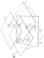
- a table arrangement according to FIGS. 1 and 2 is used in Coffee table area and stands on a solid surface 1.
- the Table arrangement has three rectangular table tops 2, which are preferably can be made of glass.
- Each table top 2 is eccentric to their center and thus to their focus on a support element attached in the form of a columnar foot 3, which by means of a Bearing bush 4 is rotatably mounted in a cover plate 5.
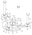
- everyone Foot 3 protrudes through the common cover plate 5, which is also rectangular is designed, through and opens below the cover plate 5 in a carrier part 7 (Fig. 2), in the illustrated embodiment is designed as a stable, open frame.
- the frame 7 does not have two specified legs that are perpendicular to each other according to Art a T-beam are integrally connected.
- the carrier part 7 also has a one-piece, unspecified positioning extension, which by one central vertical axis S, the vertical and coaxial by one shown in Fig. 2 Bearing pin M runs relative to one on the base 1 fixed base plate 6 is rotatably mounted.
- the cover plate 5 is arranged above the carrier part 7 and rotatably connected to the carrier part 7.
- the cover plate 5 of her Bottom ago by means of the screw connections indicated in Fig. 2 8 screwed to the carrier part 7.
- the cover plate 5 and the carrier part 7 serve as a control element in the sense the invention.
- a synchronization device and as a positive guidance device within the meaning of the invention are those described in more detail below Parts 9 to 13 are provided.
- Each foot 3 and thus every table top 2 is in principle in the carrier part 7 as well as in the cover plate 5 a vertical pivot axis parallel to the vertical axis S is rotatably mounted.
- Each foot 3 points above the carrier part 7 and below the Cover plate 5 each have a steering disc 9, which rotatably with the respective Foot 3 is connected.
- On each steering disc 9 engages by means of a Hinge point 12 on a transmission rod 11 to a fixed Crank disk 10, which is aligned concentrically to the vertical axis S. is leads.
- the transmission rod 11 is by means of another hinge point 13 rotatably fixed.
- the Crank disk 10 is firmly connected to the base plate 6, i.e. Likewise arranged stationary.
- the distances of the hinge points 12 to the respective Pivot axis of the associated foot 3 and the distances of the Pivot points 13 on the crank disk 10 to the vertical axis S are identical to each other.
- the straight lines connecting the vertical axis S and the axis of rotation of the inner pivot point 13 of each transmission rod 11 and the pivot axis of the associated foot 3 and the axis of rotation of the outer pivot point 12 are parallel aligned with each other, so that for each foot 3 and thus also results in a parallelogram steering for each table top 2.
- the pivoting angle of the carrier part 7 as well as the cover plate 5 is limited to a maximum of 90 ° by stops not shown in detail.
- the Alignment of the table tops 2 to each other is selected so that the outer edges the table tops 2 are parallel to each other in pairs.
- the cover plate 5 is oriented such that in the inner end position, in which the three table tops 2 the maximum coverage area have, also with their side edges parallel to the outer edges the table tops 2 is aligned. With a beginning twist the top plate 5 and the support member 7 move the table tops 2 while simultaneously rotating outwards about the central vertical axis S, whereby the spiraling fan movements of the table tops 2 result.
- the table tops 2 retain through the positive guidance means in the form of the parallelogram steering described Parallel positions in space, i.e. the assigned outer edges of the Table tops 2 always remain parallel to each other.
- the outer edges of the table tops 2 also parallel to imaginary parallel lines on the substrate 1, whereas the cover plate 5 is relatively to these imaginary parallel lines of the underground, which are fixed in space 1 twist.
- the cover plate 5 In the orientation of the Cover plate 5 has reached the outer end position of the table tops 2, whereby the table tops 2 - seen in plan view - a significantly enlarged have common usable area.
- the table tops 2 can be arranged such that they are also in the fanned out end position overlay each other in sections. However, the arrangement can also be such that there is no overlap in the fanned out end position the table top 2 is more available.
- FIG. 3 and 4 are the inner and outer end positions the table arrangement recognizable.
- Fig. 4 shows that the usable table surface the table tops 2 in the fanned out end position opposite the fanned end position is significantly enlarged.
- each table top in a corner area with an individual Letters A, B, C is in the comparison between the both end positions on the one hand the horizontal displacement of the table tops in the room and on the other hand the spatially rectified parallel shift recognizable because the letters A, B, C in both end positions have the same spatial orientation.
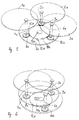
- a table arrangement according to FIGS. 5 and 6 has three circular table tops 1a to 3a, which in the illustrated embodiment Glass exist. Of course, any other is also for the table top suitable material can be used.
- Each table top 1a to 3a is eccentric to their focus and thus eccentric to their center attached to a table leg 4a to 6a, which is perpendicular to Table top protrudes downwards.
- the table legs 4a to 6a are of different heights, so that the Table tops 1a to 3a are in different parallel planes, here located in horizontal planes.
- Each table leg is therefore vertical aligned and in its lower end in a circular Base plate 7a held.
- the base plate 7a also exists in the present case Embodiment made of glass and all three table legs 4a to 6a are rotatably mounted in the common, disc-shaped base plate 7a. All three table legs 4a to 6a point to a center of the circular base plate 7a the same distance. In addition, everyone is three table legs 4a to 6a evenly over the circumference of the foot plate 7a distributed.
- the base plate 7a itself is horizontal by means of a swivel joint 13a rotatably mounted on a fixed base.
- the hinge 13a is positioned concentrically to the center of the foot plate 7a.
- the fixed one Base is through a gear wheel disc described in more detail below 11a and by one on the underside of the gear wheel 11a attached feet 12a formed, which are supported on a surface.
- the gear disc 11a is on its outer edge with a circumferential Provide spur toothing.
- Each rotating table leg 4a to 6a is below the base plate 7a, in which the table legs 4a to 6a are mounted are, a positive guide element 8a to 10a, in the present form a toothed disc with spur gearing, non-rotatable assigned.
- All positive guidance elements 8a to 10a are in the arranged on the same horizontal plane as the fixed gear wheel 11a.
- the spur gears of the positive guide elements 8a to 10a and the gear wheel 11a are coordinated, so that the positive guide elements 8a to 10a with the gear wheel Comb 11a.
- the gear wheel 11a and the positive guide elements 8a to 10a are part of the common synchronizer for a common Movement of the table top 1a to 3a.
- the gear disc 11a and the positive guide elements 10a form the positive guide means in Sense of the invention.
- the footplate serves as the control element 7a.
- the Base plate held stationary. This is the central gear disc rotatable, so that the functions of the gear disc and the Invert the footplate. The table legs then remain on one stationary place. Nevertheless, the desired fanning out or fanning out results.
- both the table tops 1a to 3a and the base plate 7a consist of transparent glass, the parts lying one below the other are not dashed, but shown with solid lines.
- the positive guidance means can in other, not shown embodiments the invention by others, non-positively or positively components which are connected to one another in a force-transmitting manner be educated. So are chain drives or belt drives in particular frictional transfers also provided.
- FIGS. 7 to 9 there are also three Table tops 1 b to 3b eccentrically on each table leg 4b to 6b held.
- a circular control plate 7b serves as the control element, that with the help of rectified eccentrics 10b parallel to one a base plate 11b in its plate plane tumbling around a central, unspecified vertical axis of the Base plate 11b is movably supported.
- the foot plate 11b is at illustrated embodiment also circular and has a smaller diameter than the control plate 7b.
- the lower plate as a wobble control plate and the upper plate, in which the table legs are rotatably supported serves as on the base or base plate is fixed to the ground. This is then by means of corresponding feet supported on the floor to avoid a wobbling Mobility of the control plate below the base or base plate to enable.
- the mode of operation corresponds to that shown here Embodiment in reverse.
- the table legs 4b, 5b, 6b are in the control plate 7b by means of a corresponding Bearings 9b rotatably mounted.
- a tax appendage each Table legs 4b to 6b project downwards through the control plate 7b through and is at a distance from the bearing with the respective eccentric 10b 8b firmly connected.
- the control plate 7b protruding control extension of each table leg 4b to 6b on his lower end on a downward protruding threaded bolt that with an eccentric nut cooperates such that the respective Table leg 4b to 6b is screwed onto the eccentric.
- the control plate In order for a fanning or fanning movement of the table tops 1b to 3b, the control plate is easily in a circumferential direction emotional. This will over the control plate through which penetrate all three table legs 4b to 6b, a torque on the three eccentrics 10b exerted, causing them about their respective axes of rotation in the area of the bearings 8b relative to the fixed lower one Base plate 11b are rotated. Since the table legs 4b to 6b with the eccentrics 10b are firmly connected, they inevitably rotate a rotational movement of the eccentrics 10b inwards or outwards With. To prevent the entire arrangement from locking itself, Of course, all three eccentrics 10b must be parallel to each other be aligned.
Abstract
Description
Die Erfindung betrifft eine Tischanordnung mit wenigstens zwei Tischplatten, die in unterschiedlichen Parallelebenen beweglich angeordnet sind, die einander in wenigstens einer inneren Stellung zumindest abschnittsweise überlagern und die mittels einer Synchronisiereinrichtung für gemeinsame Bewegungen gekoppelt sind.The invention relates to a table arrangement with at least two table tops, which are arranged to move in different parallel planes are mutually at least in sections in at least one inner position superimpose and by means of a synchronization device are coupled for common movements.
Eine solche Tischanordnung ist aus dem US-Patent 5 458 070 bekannt. In dem US-Patent sind mehrere Ausführungsformen beschrieben und dargestellt. Bei einer Ausführung mit drei Tischplatten, die in unterschiedlichen Horizontalebenen zueinander angeordnet sind, ist jede Tischplatte auf einem Tischbein exzentrisch zu ihrem Schwerpunkt gehalten. Die Tischbeine sind in einem gemeinsamen, feststehenden Sockel drehbar gelagert. In dem Sockel ist eine Synchronisiereinrichtung vorgesehen, die die drei Tischbeine der Tischplatten für gemeinsame Bewegungen miteinander koppelt. In einer inneren Endposition überlagern die drei Tischplatten einander abschnittsweise. In einer um 180° nach außen gedrehten Endposition ist die gemeinsame nutzbare Grundfläche der Tischplatten gegenüber der inneren Endposition vergrößert, da sich die Tischplatten in der äußeren Endposition nicht mehr überlagern.Such a table arrangement is known from US Pat. No. 5,458,070. Several embodiments are described and in the US patent shown. In a version with three table tops, in different Horizontal planes are arranged to each other, is each Tabletop on a table leg eccentric to its focus held. The table legs are in a common, fixed Base rotatably mounted. There is a synchronizer in the base provided that the three table legs of the table tops for common Coupling movements. Overlay in an inner end position the three table tops in sections. In one by 180 ° the end position turned outwards is the common usable base area the table tops are enlarged compared to the inner end position, since the table tops no longer overlap in the outer end position.
Aufgabe der Erfindung ist es, eine Tischanordnung der eingangs genannten Art zu schaffen, die eine weiter verbesserte Variabilität der Tischplattenanordnung ermöglicht.The object of the invention is a table arrangement of the aforementioned Kind of creating a further improved variability of the Table top arrangement allows.
Diese Aufgabe wird dadurch gelöst, dass die Synchronisiereinrichtung mit wenigstens einem um eine zentrale Hochachse planar beweglichen Steuerelement versehen ist, das durch Zwangsführungsmittel auf die Tischplatten spiralförmige Steuerkurven derart ausübt, dass die Tischplatten zwischen der wenigstens einen inneren Stellung und wenigstens einer äußeren Stellung, in der die Tischplatten eine vergrößerte gemeinsame Nutzfläche darstellen, auf- oder zufächerbar sind. Unter der planaren Beweglichkeit des Steuerelementes ist eine ebene, zweidimensionale Bewegung zu verstehen. Hierzu zählen sowohl Dreh- als auch Schwenkbewegungen als auch Taumel-, Pendel- oder Schwimmbewegungen. Die Bewegungen erfolgen jeweils um eine imaginäre zentrale Hochachse, wobei dieser Begriff weit gefasst verstanden sein soll. Denn bei einer für jede Umdrehung wiederkehrenden Taumelbewegung bewegt sich das Steuerelement zwangsläufig ständig exzentrisch um die zentrale Hochachse herum. Dennoch bildet die zentrale Hochachse ein Zentrum, um das das Steuerelement bei einer Taumelbewegung herumbewegt wird.This object is achieved in that the synchronization device with at least one movable planar about a central vertical axis Control is provided by the positive control means on the Table tops exerts spiral control curves such that the table tops between the at least one inner position and at least an outer position in which the table tops have an enlarged joint Represent usable space that can be fanned in or fanned out. Under the planar The mobility of the control element is a flat, two-dimensional one To understand movement. This includes both turning and Swivel movements as well as wobble, pendulum or swimming movements. The movements take place around an imaginary central one Vertical axis, this term should be understood broadly. Because with a wobbling movement repeated for each revolution the control is inevitably constantly eccentric central vertical axis around. Nevertheless, the central vertical axis forms Center around which the control element moves when it wobbles becomes.
In Ausgestaltung der Erfindung ist das Steuerelement um die zentrale Hochachse drehbeweglich gelagert. Dies ist eine vorteilhafte Ausgestaltung, um eine begrenzte, endlose Auf- und Zufächerung zu erzielen.In one embodiment of the invention, the control element is around the central one Vertical axis rotatably mounted. This is an advantageous embodiment to achieve a limited, endless fanning and fanning.
In weiterer Ausgestaltung der Erfindung ist jeder Tischplatte eine Parallelogrammlenkung zugeordnet, wobei alle Parallelogrammlenkungen einen gemeinsamen Zentralgelenkpunkt aufweisen, der konzentrisch zu der zentralen Hochachse angeordnet ist. Vorteilhaft ist das Steuerelement lediglich begrenzt, vorzugsweise um 90°, verdrehbar. Die Parallelogrammlenkungen sind vorteilhaft derart angeordnet, dass sie sich gegenseitig nicht behindern. Die Grundidee dieser Ausführungsform ist es, mit einer Drehbewegung des Steuerelementes im Raum geradlinige oder gekrümmte Parallelverlagerungen aller Tischplatten gemeinsam nach außen oder innen zu erzwingen. Durch die Parallelverlagerung der Tischplatten wird gegenüber einer Schwenkbewegung der Tischplatten ein reduzierter Raum für eine entsprechende Verlagerungsbewegung der Tischplatten benötigt, so dass die Tischanordnung insbesondere auch bei beengten Raumverhältnissen vorteilhaft einsetzbar ist. Die erfindungsgemäße Lösung sieht bevorzugt vor, dass die Tischplatten relativ zueinander sowie relativ zu der zentralen Hochachse spiralförmige Bewegungen unter Beibehaltung ihrer parallelen Ausrichtung im Raum durchführen. Alternativ ist es auch möglich, die Tischplatten in von der zentralen Hochachse radial nach außen verlaufenden Linearführungen zu verlagern, wobei bei einer solchen Ausführung das Steuerelement für jede Tischplatte mit einer entsprechenden spiralförmigen Steuerkontur versehen ist, die bei einer Drehbewegung des Steuerelementes die jeweilige Tischplatte gleichmäßig nach außen verschiebt. Dadurch ergibt sich die Auffächerungsbewegung. Entsprechend umgekehrt erfolgt selbstverständlich die Zufächerung bis hin zur inneren Endposition. Bei der ersten, bevorzugten Ausführung verlagern sich die Tischplatten unter Beibehaltung ihrer Parallelausrichtung spiralförmig im Raum, wodurch eine besonders harmonische Auffächerungs- oder Zufächerungsbewegung erzielbar ist. Besonders vorteilhaft ist die erfindungsgemäße Lösung für drei Tischplatten geeignet, da dann die parallele Auffächerungsbewegung optisch besonders eindrucksvoll ist. Zudem wird durch das Vorsehen von drei Tischplatten die Nutzfläche in der aufgefächerten Endposition erheblich vergrößert. In bevorzugter Weise ist die Tischanordnung im Couchtischbereich einsetzbar. In a further embodiment of the invention, each table top is a parallelogram steering assigned, with all parallelogram steering have a common central articulation point that is concentric to the central vertical axis is arranged. The control element is advantageous only rotatable to a limited extent, preferably by 90 °. The parallelogram steering are advantageously arranged so that they are mutually do not hinder. The basic idea of this embodiment is with a rotary movement of the control element in the line or straight curved parallel displacements common to all table tops to force outwards or inwards. By moving the Tabletops are opposed to a swiveling movement of the tabletops a reduced space for a corresponding shift movement the table tops needed, so the table arrangement in particular can also be used advantageously in confined spaces. The invention Solution preferably provides that the table tops are relative to each other as well as relative to the central vertical axis Movements while maintaining their parallel alignment in space carry out. Alternatively, it is also possible to move the table tops in from the central vertical axis radially outward linear guides to shift, the control element for each table top with a corresponding spiral control contour is provided, the respective one when the control element rotates Table top moves evenly outwards. This gives the fanning out movement. The reverse is done accordingly of course the fanning to the inner end position. at In the first, preferred version, the table tops move under Maintaining their parallel alignment spirally in space, which makes a particularly harmonious fanning or fanning movement is achievable. The one according to the invention is particularly advantageous Solution suitable for three table tops, because then the parallel fanning movement is particularly visually impressive. In addition, through the provision of three table tops in the fanned out area End position significantly enlarged. The table arrangement is preferred Can be used in the coffee table area.
In weiterer Ausgestaltung der Erfindung ist das drehbare Steuerelement als Trägerteil gestaltet, in dem die Tischplatten mit Hilfe von Stützelementen um zu der zentralen Hochachse parallele Schwenkachsen drehbar gelagert sind, und die Parallelogrammlenkungen sind mit den Stützelementen verbunden. Als Stützelemente können Füße, Sockel, Säulen oder Beine vorgesehen sein, die jeweils eine Tischplatte tragen.In a further embodiment of the invention, the rotatable control element designed as a support part in which the table tops with the help of support elements rotatable about pivot axes parallel to the central vertical axis are stored, and the parallelogram steering are with the Support elements connected. Feet, base, Columns or legs can be provided, each carrying a table top.
In weiterer Ausgestaltung der Erfindung ist das Steuerelement anschlaglos um die zentrale Hochachse drehbar. Hierdurch ist vorteilhaft eine stufenlose und endlose Auf- und Zufächerung erzielbar. Die Variabilität bei der Vergrößerung oder Verkleinerung der gemeinsamen Nutzfläche aller Tischplatten gegenüber dem Stand der Technik wird hierdurch erheblich erhöht.In a further embodiment of the invention, the control element is without a stop rotatable around the central vertical axis. This is advantageous a continuous and endless fanning and fanning can be achieved. The variability when enlarging or reducing the common usable area all table tops compared to the state of the art significantly increased.
In weiterer Ausgestaltung der Erfindung ist jeder Tischplatte ein Zwangsführungselement zugeordnet, das Teil der Synchronisiereinrichtung ist, wobei alle Zwangsführungselemente bei einer Drehbewegung des Steuerelementes planetenartig um die zentrale Hochachse umlaufen. Falls jede Tischplatte auf einem einzelnen Tischbein gehalten ist, und jedem Tischbein ein entsprechendes Zwangsführungselement zugeordnet ist, so ergibt sich der verblüffende Effekt, dass bei einer Drehbewegung des Steuerelementes und einer daraus resultierenden Auf- oder Zufächerung der Tischplatten die Tischbeine um die zentrale Hochachse umlaufen.In a further embodiment of the invention, each table top is a positive guide element assigned, which is part of the synchronization device, all the positive guide elements during a rotary movement of the control element revolve like a planet around the central vertical axis. If each table top is held on a single table leg, and each Table leg is assigned a corresponding positive guidance element, this results in the astonishing effect that when the Control element and a resulting fanning or fanning the table tops round the table legs around the central vertical axis.
In weiterer Ausgestaltung der Erfindung ist das Steuerelement in exzentrischen Taumelbewegungen relativ zu der zentralen Hochachse beweglich. Hierdurch ist eine stufen- und endlose Auf- und Zufächerung erzielbar. Vorteilhaft steht das Steuerelement mit Hilfe von gleichgerichteten Exzentern, die jeweils einer Tischplatte zugeordnet sind, mit den Tischplatten in Wirkverbindung. Die Exzenter schaffen somit die Taumelbewegungen für das Steuerelement. Vorzugsweise ist das Steuerelement als ebene Platte gestaltet.In a further embodiment of the invention, the control element is eccentric Tumbling movements are movable relative to the central vertical axis. In this way, a continuous and endless fanning and fanning can be achieved. The control element advantageously stands with the help of rectified Eccentrics, each assigned to a table top, with the Table tops in active connection. The eccentrics thus create the wobble movements for the control. The control element is preferably designed as a flat plate.
Weitere Vorteile und Merkmale der Erfindung ergeben sich aus der Ansprüchen sowie aus der nachfolgenden Beschreibung bevorzugter Ausführungsbeispiele der Erfindung, die anhand der Zeichnungen dargestellt sind.
- Fig. 1
- zeigt in perspektivischer Darstellung eine Schrägansicht einer Ausführungsform einer erfindungsgemäßen Tischanordnung von oben, wobei die Tischanordnung drei Tischplatten aufweist,
- Fig. 2
- die Synchronisiereinrichtung für die Tischplatten der Tischanordnung nach Fig. 1 in perspektivischer Darstellung, wobei aus Übersichtlichkeitsgründen die Tischplatten sowie eine Deckplatte entfernt sind,
- Fig. 3
- in einer Draufsicht die Tischanordnung nach Fig. 1 in einer zugefächerten Endposition,
- Fig. 4
- die Tischanordnung in einer aufgefächerten Endposition,
- Fig. 5
- in perspektivischer Darstellung eine weitere Ausführungsform einer erfindungsgemäßen Tischanordnung in einer aufgefächerten Position,
- Fig. 6
- die Tischanordnung nach Fig. 5 in einer zugefächerten Minimal-stellung,
- Fig. 7
- in perspektivischer Darstellung eine weitere Ausführungsform einer erfindungsgemäßen Tischanordnung,
- Fig. 8
- die Tischanordnung nach Fig. 7 in einer Seitenansicht und
- Fig. 9
- einen vergrößerten Ausschnitt der Tischanordnung nach den Fig. 7 und 8 auf Höhe eines Tischbeines.
- Fig. 1
- shows a perspective view of an oblique view of an embodiment of a table arrangement according to the invention from above, the table arrangement having three table tops,
- Fig. 2
- 1 in a perspective view, the table tops and a cover plate being removed for reasons of clarity,
- Fig. 3
- 1 in a flattened end position,
- Fig. 4
- the table arrangement in a fanned out end position,
- Fig. 5
- a perspective view of a further embodiment of a table arrangement according to the invention in a fanned out position,
- Fig. 6
- 5 in a fanned minimum position,
- Fig. 7
- a perspective view of another embodiment of a table arrangement according to the invention,
- Fig. 8
- 7 in a side view and
- Fig. 9
- an enlarged section of the table arrangement according to FIGS. 7 and 8 at the level of a table leg.
Eine Tischanordnung nach den Fig. 1 und 2 dient zum Einsatz im
Couchtischbereich und steht auf einem festen Untergrund 1 auf. Die
Tischanordnung weist drei rechteckige Tischplatten 2 auf, die vorzugsweise
aus Glas hergestellt sein können. Jede Tischplatte 2 ist exzentrisch
zu ihrer Mitte und damit zu ihrem Schwerpunkt auf einem Stützelement
in Form eines säulenförmigen Fußes 3 befestigt, der mittels einer
Lagerbuchse 4 in einer Deckplatte 5 drehbeweglich gelagert ist. Jeder
Fuß 3 ragt durch die gemeinsame Deckplatte 5, die ebenfalls rechteckig
gestaltet ist, hindurch und mündet unterhalb der Deckplatte 5 in
einen Trägerteil 7 (Fig. 2), der beim dargestellten Ausführungsbeispiel
als stabiler, offener Rahmen gestaltet ist. Der Rahmen 7 weist zwei nicht
näher bezeichnete Schenkel auf, die rechtwinklig zueinander nach Art
eines T-Trägers einstückig miteinander verbunden sind. An den Enden
der Schenkel sind die Füße 3 mit ihren unteren Stirnenden drehbeweglich
aufgenommen. Der Trägerteil 7 weist zudem einen einstückig angeformten,
nicht näher bezeichneten Lagerungsfortsatz auf, der um eine
zentrale Hochachse S, die vertikal und koaxial durch einen in Fig. 2 dargestellten
Lagerbolzen M verläuft, relativ zu einer auf dem Untergrund 1
feststehenden Sockelplatte 6 drehbar gelagert ist.A table arrangement according to FIGS. 1 and 2 is used in
Coffee table area and stands on a solid surface 1. The
Table arrangement has three rectangular table tops 2, which are preferably
can be made of glass. Each
Die Deckplatte 5 ist oberhalb des Trägerteiles 7 angeordnet und drehfest
mit dem Trägerteil 7 verbunden. Hierzu ist die Deckplatte 5 von ihrer
Unterseite her mittels der in Fig. 2 angedeuteten Schraubverbindungen
8 mit dem Trägerteil 7 verschraubt.The
Die Deckplatte 5 und der Trägerteil 7 dienen als Steuerelement im Sinne
der Erfindung. Als Synchronisiereinrichtung und als Zwangsführungsmittel
im Sinne der Erfindung sind die nachfolgend näher beschriebenen
Teile 9 bis 13 vorgesehen. Jeder Fuß 3 und damit auch jede Tischplatte
2 ist grundsätzlich in dem Trägerteil 7 wie auch in der Deckplatte 5 um
eine vertikale, zur Hochachse S parallele Schwenkachse drehbar gelagert.
Jeder Fuß 3 weist oberhalb des Trägerteiles 7 und unterhalb der
Deckplatte 5 jeweils eine Lenkscheibe 9 auf, die drehfest mit dem jeweiligen
Fuß 3 verbunden ist. An jeder Lenkscheibe 9 greift mittels eines
Gelenkpunktes 12 eine Übertragungsstange 11 an, die zu einer feststehenden
Kurbelscheibe 10, die konzentrisch zur Hochachse S ausgerichtet
ist, führt. An der Kurbelscheibe 10 ist die Übertragungsstange 11 mittels
eines weiteren Gelenkpunktes 13 drehbeweglich festgelegt. Die
Kurbelscheibe 10 ist fest mit der Sockelplatte 6 verbunden, d.h. ebenfalls
stationär angeordnet. Die Abstände der Gelenkpunkte 12 zur jeweiligen
Schwenkachse des zugeordneten Fußes 3 und die Abstände der
Gelenkpunkte 13 an der Kurbelscheibe 10 zur Hochachse S sind identisch
zueinander. Die Verbindungsgeraden, die zwischen der Hochachse
S und der Drehachse des inneren Gelenkpunktes 13 jeder Übertragungsstange
11 und der Schwenkachse des zugeordneten Fußes 3 sowie
der Drehachse des äußeren Gelenkpunktes 12 verlaufen, sind parallel
zueinander ausgerichtet, so dass sich für jeden Fuß 3 und damit auch
für jede Tischplatte 2 eine Parallelogrammlenkung ergibt.The
Der Schwenkwinkel des Trägerteiles 7 wie auch der Deckplatte 5 ist
durch nicht näher dargestellte Anschläge auf maximal 90° begrenzt. Die
Ausrichtung der Tischplatten 2 zueinander ist so gewählt, dass die Außenkanten
der Tischplatten 2 jeweils paarweise zueinander parallel sind.
Die Deckplatte 5 ist derart ausgerichtet, dass sie in der inneren Endposition,
in der die drei Tischplatten 2 den maximalen Überdeckungsbereich
aufweisen, ebenfalls mit ihren Seitenkanten parallel zu den Außenkanten
der Tischplatten 2 ausgerichtet ist. Bei einer beginnenden Verdrehung
der Deckplatte 5 und des Trägerteiles 7 wandern die Tischplatten
2 unter gleichzeitiger Drehung um die zentrale Hochachse S nach außen,
wodurch sich die spiralförmigen Auffächerbewegungen der Tischplatten
2 ergeben. Die Tischplatten 2 behalten durch die Zwangsführungsmittel
in Form der beschriebenen Parallelogrammlenkungen ihre
Parallelstellungen im Raum bei, d.h. die zugeordneten Außenkanten der
Tischplatten 2 bleiben immer parallel zueinander. Insbesondere bleiben
die Außenkanten der Tischplatten 2 auch parallel zu imaginären Parallelgeraden
auf dem Untergrund 1, wohingegen die Deckplatte 5 sich relativ
zu diesen im Raum festen imaginären Parallelgeraden des Untergrundes
1 verdrehen. In der um 90° verschwenkten Ausrichtung der
Deckplatte 5 ist die äußere Endposition der Tischplatten 2 erreicht, wodurch
die Tischplatten 2 - in Draufsicht gesehen - eine wesentlich vergrößerte
gemeinsame Nutzfläche aufweisen. Die Tischplatten 2 können
derart angeordnet sein, dass sie auch in der aufgefächerten Endposition
einander noch abschnittsweise überlagern. Die Anordnung kann jedoch
auch so erfolgt sein, dass in der aufgefächerten Endposition keine Überdeckung
der Tischplatten 2 mehr vorhanden ist.The pivoting angle of the
Anhand der Fig. 3 und 4 sind die inneren und äußeren Endpositionen der Tischanordnung erkennbar. Fig. 4 zeigt, dass die nutzbare Tischfläche der Tischplatten 2 in der aufgefächerten Endposition gegenüber der zugefächerten Endposition erheblich vergrößert ist. Zum besseren Verständnis ist jede Tischplatte in einem Eckbereich mit einem individuellen Buchstaben A, B, C versehen. Dadurch ist im Vergleich zwischen den beiden Endpositionen zum einen die Horizontalverlagerung der Tischplatten im Raum und zum anderen die räumlich gleichgerichtete Parallelverlagerung erkennbar, da die Buchstaben A, B, C in beiden Endpositionen die gleiche Raumausrichtung aufweisen.3 and 4 are the inner and outer end positions the table arrangement recognizable. Fig. 4 shows that the usable table surface the table tops 2 in the fanned out end position opposite the fanned end position is significantly enlarged. For better understanding is each table top in a corner area with an individual Letters A, B, C. This is in the comparison between the both end positions on the one hand the horizontal displacement of the table tops in the room and on the other hand the spatially rectified parallel shift recognizable because the letters A, B, C in both end positions have the same spatial orientation.
Eine Tischanordnung nach den Fig. 5 und 6 weist drei kreisrunde Tischplatten
1a bis 3a auf, die beim dargestellten Ausführungsbeispiel aus
Glas bestehen. Selbstverständlich ist für die Tischplatte auch jedes andere
geeignete Material einsetzbar. Jede Tischplatte 1a bis 3a ist exzentrisch
zu ihrem Schwerpunkt und damit exzentrisch zu ihrem Mittelpunkt
auf einem Tischbein 4a bis 6a befestigt, das rechtwinklig zur
Tischplatte nach unten abragt. Beim dargestellten Ausführungsbeispiel
sind die Tischbeine 4a bis 6a unterschiedlich hoch gestaltet, so dass die
Tischplatten 1a bis 3a sich in unterschiedlichen Parallelebenen, vorliegend
in Horizontalebenen befinden. Jedes Tischbein ist demzufolge vertikal
ausgerichtet und in seinem unterem Endbereich in einer kreisrunden
Fußplatte 7a gehalten. Auch die Fußplatte 7a besteht beim vorliegenden
Ausführungsbeispiel aus Glas und alle drei Tischbeine 4a bis 6a
sind in der gemeinsamen, scheibenförmigen Fußplatte 7a drehbar gelagert.
Alle drei Tischbeine 4a bis 6a weisen zu einem Mittelpunkt der
kreisförmigen Fußplatte 7a den gleichen Abstand auf. Zudem sind alle
drei Tischbeine 4a bis 6a gleichmäßig über den Umfang der Fußplatte
7a verteilt.A table arrangement according to FIGS. 5 and 6 has three circular table tops
1a to 3a, which in the illustrated embodiment
Glass exist. Of course, any other is also for the table top
suitable material can be used. Each table top 1a to 3a is eccentric
to their focus and thus eccentric to their center
attached to a
Die Fußplatte 7a selbst ist mittels eines Drehgelenkes 13a horizontal
drehbar auf einem feststehenden Sockel gelagert. Das Drehgelenk 13a
ist konzentrisch zum Mittelpunkt der Fußplatte 7a positioniert. Der feststehende
Sockel ist durch eine nachfolgend näher beschriebene Zahnradscheibe
11a sowie durch ein an der Unterseite der Zahnradscheibe
11a befestigte Füße 12a gebildet, die sich auf einem Untergrund abstützen.
Die Zahnradscheibe 11a ist an ihrem Außenrand mit einer umlaufenden
Stirnverzahnung versehen. Jedem drehbaren Tischbein 4a bis
6a ist unterhalb der Fußplatte 7a, in der die Tischbeine 4a bis 6a gelagert
sind, ein Zwangsführungselement 8a bis 10a, vorliegend in Form
einer mit einer Stirnverzahnung versehenen Verzahnungsscheibe, drehfest
zugeordnet. Alle Zwangsführungselemente 8a bis 10a sind in der
gleichen Horizontalebene angeordnet wie die feststehende Zahnradscheibe
11a. Die Stirnverzahnungen der Zwangsführungselemente 8a
bis 10a und der Zahnradscheibe 11a sind aufeinander abgestimmt, so
dass die Zwangsführungselemente 8a bis 10a mit der Zahnradscheibe
11a kämmen. The base plate 7a itself is horizontal by means of a swivel joint 13a
rotatably mounted on a fixed base. The hinge 13a
is positioned concentrically to the center of the foot plate 7a. The fixed one
Base is through a gear wheel disc described in more detail below
11a and by one on the underside of the
Die Zahnradscheibe 11a sowie die Zwangsführungselemente 8a bis 10a
sind Teil der gemeinsamen Synchronisiereinrichtung für eine gemeinsame
Bewegung der Tischplatte 1a bis 3a. Die Zahnradscheibe 11a und
die Zwangsführungselemente 10a bilden die Zwangsführungsmittel im
Sinne der Erfindung. Als Steuerelement dient vorliegend die Fußplatte
7a.The
Bei einem nicht dargestellten Ausführungsbeispiel der Erfindung wird die Fußplatte stationär gehalten. Dafür ist die zentrale Zahnradscheibe drehbeweglich, so dass sich die Funktionen der Zahnradscheibe und der Fußplatte umkehren. Die Tischbeine verbleiben dann zwar an einem stationären Ort. Dennoch ergibt sich die gewünschte Auf- oder Zufächerung.In an embodiment of the invention, not shown, the Base plate held stationary. This is the central gear disc rotatable, so that the functions of the gear disc and the Invert the footplate. The table legs then remain on one stationary place. Nevertheless, the desired fanning out or fanning out results.
Da beim Ausführungsbeispiel nach den Fig. 5 und 6 sowohl die Tischplatten 1a bis 3a als auch die Fußplatte 7a aus transparenten Glas bestehen, sind die jeweils untereinander liegenden Teile nicht gestrichelt, sondern mit durchgezogenen Linien dargestellt.Since in the embodiment of FIGS. 5 and 6, both the table tops 1a to 3a and the base plate 7a consist of transparent glass, the parts lying one below the other are not dashed, but shown with solid lines.
Sobald bei der Tischanordnung nach den Fig. 5 und 6 manuell eine der
Tischplatten 1a bis 3a im Uhrzeigersinn oder im Gegenuhrzeigersinn
gedrückt oder gezogen wird, beginnt sich die entsprechende Tischplatte
um die Drehachse des zugeordneten Tischbeines 4a bis 6a zu drehen.
Hierdurch rollt das zugeordnete Zwangsführungselement 8a bis 10a auf
dem Außenumfang der Zahnradscheibe 11a ab. Durch die Lagerung in
der Fußplatte 7a wird diese in der entsprechenden Drehrichtung mit verdreht
und nimmt auch die übrigen Tischbeine mit. Da auch die Zwangsführungselemente
8a bis 10a der übrigen Tischbeine 4a bis 6a mit der
Stirnverzahnung der Zahnradscheibe 11a kämmen, werden zwangsläufig
auch diese mit bewegt. Jede Tischplatte führt zwischen der in Fig. 6
dargestellten inneren Minimalstellung und einer äußeren Maximalstellung,
in der die Tischplatten 1a bis 3a maximal aufgefächert sind, spiralförmige
Steuerkurven durch. Da alle Tischplatten 1a bis 3a umlaufend
ohne Anschlag beweglich sind, kann bei mehreren Umdrehungen in einer
Drehrichtung ein alternierendes Auf- und Zufächern der Tischplatten
1a bis 3a erzielt werden. Da die Durchmesser der Verzahnungsscheiben
in Form der Zwangsführungselemente 8a bis 10a wesentlich geringer
sind als der Durchmesser der Stirnverzahnung der Zahnradscheibe 11a,
ergibt sich zusätzlich ein relativ großes Übersetzungsverhältnis. Relativ
geringe Drehwinkel der Fußplatte 7a führen demzufolge bereits zur relativ
großen Drehwinkeln der Tischplatten. Wie anhand der Fig. 5 und 6
erkennbar ist, bewirkt bereits ein Drehwinkel der Fußplatte 7a von etwa
20° bis 30° eine Verdrehung jeder Tischplatte 1a bis 3a um etwa 180°.As soon as one of the table arrangement according to FIGS. 5 and 6
Table tops 1a to 3a clockwise or counterclockwise
is pressed or pulled, the corresponding table top begins
to rotate the axis of rotation of the associated
Die Zwangsführungsmittel können bei anderen, nicht dargestellten Ausführungsformen der Erfindung auch durch andere, kraft- oder formschlüssig miteinander kraftübertragend in Verbindung stehende Bauteile gebildet sein. So sind insbesondere Ketten- oder Riementriebe oder auch reibschlüssige Übertragungen vorgesehen.The positive guidance means can in other, not shown embodiments the invention by others, non-positively or positively components which are connected to one another in a force-transmitting manner be educated. So are chain drives or belt drives in particular frictional transfers also provided.
Beim Ausführungsbeispiel nach den Fig. 7 bis 9 sind ebenfalls drei
Tischplatten 1 b bis 3b exzentrisch auf jeweils einem Tischbein 4b bis 6b
gehalten. Als Steuerelement dient hier eine kreisförmige Steuerplatte 7b,
die mit Hilfe von gleichgerichteten Exzentern 10b parallel zu einer auf
einem Untergrund aufstehenden Fußplatte 11b in ihrer Plattenebene
taumelnd um eine zentrale, nicht näher bezeichnete Hochachse der
Fußplatte 11b herum beweglich gelagert ist. Die Fußplatte 11b ist beim
dargestellten Ausführungsbeispiel ebenfalls kreisförmig gestaltet und
weist einen geringeren Durchmesser auf als die Steuerplatte 7b. Als Exzenter
10b sind flache zylindrische Scheiben vorgesehen, die auf einer
Seite exzentrisch mittels einer Lagerung 8b drehbeweglich an der Fußplatte
11b und - jeweils auf ihre Mittelhochachse bezogen gegenüberliegend
- mittels einer Befestigung drehfest in nachfolgend näher beschriebener
Weise mit einem die Steuerplatte 7b durchdringenden
Steuerfortsatz des jeweiligen Tischbeines 4b, 5b, 6b in Verbindung stehen.In the embodiment according to FIGS. 7 to 9 there are also three
Table tops 1 b to 3b eccentrically on each table leg 4b to 6b
held. A
Bei einem nicht dargestellten Ausführungsbeispiel der Erfindung dient die untere Platte als taumelbewegliche Steuerplatte und die obere Platte, in der die Tischbeine drehbeweglich abgestützt sind, dient als auf dem Untergrund feststehende Sockel- oder Fußplatte. Dies ist dann mittels entsprechender Füße auf dem Boden abgestützt, um eine taumelnde Beweglichkeit der Steuerplatte unterhalb der Boden- oder Fußplatte zu ermöglichen. Die Funktionsweise entspricht dem hier dargestellten Ausführungsbeispiel in umgekehrter Weise.In an embodiment of the invention, not shown, is used the lower plate as a wobble control plate and the upper plate, in which the table legs are rotatably supported serves as on the base or base plate is fixed to the ground. This is then by means of corresponding feet supported on the floor to avoid a wobbling Mobility of the control plate below the base or base plate to enable. The mode of operation corresponds to that shown here Embodiment in reverse.
Wie anhand der Fig. 9 erkennbar ist, ergibt sich durch die eingesetzten
Lagerungen 8b ein äußerst flacher Unterbau. Die Lagerung 8b ist durch
ein Axiallager gebildet, das mittels einer Senkschraube 12b auf der Bodenplatte
11b befestigt ist.As can be seen from FIG. 9, results from the ones used
Die Tischbeine 4b, 5b, 6b sind in der Steuerplatte 7b mittels entsprechender
Lagerungen 9b drehbeweglich gelagert. Ein Steuerfortsatz jedes
Tischbeines 4b bis 6b ragt durch die Steuerplatte 7b nach unten
hindurch und ist mit dem jeweiligen Exzenter 10b in Abstand zu der Lagerung
8b fest verbunden. Hierzu weist der durch die Steuerplatte 7b
hindurchragende Steuerfortsatz jedes Tischbeines 4b bis 6b an seinem
unteren Ende einen nach unten abragenden Gewindebolzen auf, der mit
einer exzenterseitigen Mutter derart zusammenwirkt, dass das jeweilige
Tischbein 4b bis 6b auf dem Exzenter festgeschraubt wird.The table legs 4b, 5b, 6b are in the
Um nun eine Auf- oder Zufächerungsbewegung der Tischplatten 1b bis
3b zu erzielen, wird die Steuerplatte in einfacher Weise in einer Umfangsrichtung
bewegt. Hierdurch wird über die Steuerplatte, durch die
alle drei Tischbeine 4b bis 6b hindurchdringen, ein Drehmoment auf die
drei Exzenter 10b ausgeübt, wodurch diese um ihre jeweiligen Drehachsen
im Bereich der Lagerungen 8b relativ zur feststehenden unteren
Fußplatte 11b verdreht werden. Da die Tischbeine 4b bis 6b mit den Exzentern
10b fest verbunden sind, drehen diese sich zwangsläufig bei
einer Drehbewegung der Exzentern 10b nach innen oder nach außen
mit. Um eine Selbsthemmung der gesamten Anordnung zu verhindern,
müssen selbstverständlich alle drei Exzenter 10b parallel zueinander
ausgerichtet sein. Dies heißt, dass die drei Ebenen der Tischbeine 4b
bis 6b, die sowohl die Mittellängsachse des jeweiligen Tischbeines 4b,
5b, 6b aufnehmen, als auch die jeweiligen Drehachsen der Lagerungen
8b, parallel zueinander ausgerichtet sind. Durch die Exzenterlagerung
der Steuerplatte ist somit ein anschlagloses Auf- und Zufächern der
Tischplatten 1b bis 3b erzielbar.In order for a fanning or fanning movement of the table tops 1b to
3b, the control plate is easily in a circumferential direction
emotional. This will over the control plate through which
penetrate all three table legs 4b to 6b, a torque on the
three eccentrics 10b exerted, causing them about their respective axes of rotation
in the area of the
Claims (9)
Applications Claiming Priority (4)
| Application Number | Priority Date | Filing Date | Title |
|---|---|---|---|
| DE2001102400 DE10102400A1 (en) | 2001-01-12 | 2001-01-12 | Table arrangement comprises two table plates arranged to move in different parallel planes and coupled together using a synchronizing unit provided with a control element moving about a central axis |
| DE10102400 | 2001-01-12 | ||
| DE2001150397 DE10150397A1 (en) | 2001-10-05 | 2001-10-05 | Table arrangement with at least two table tops |
| DE10150397 | 2001-10-05 |
Publications (3)
| Publication Number | Publication Date |
|---|---|
| EP1222876A2 true EP1222876A2 (en) | 2002-07-17 |
| EP1222876A3 EP1222876A3 (en) | 2002-07-24 |
| EP1222876B1 EP1222876B1 (en) | 2004-03-24 |
Family
ID=26008284
Family Applications (1)
| Application Number | Title | Priority Date | Filing Date |
|---|---|---|---|
| EP02000437A Expired - Lifetime EP1222876B1 (en) | 2001-01-12 | 2002-01-08 | Arrangement for a table with at least two table-tops |
Country Status (3)
| Country | Link |
|---|---|
| EP (1) | EP1222876B1 (en) |
| AT (1) | ATE262296T1 (en) |
| DE (1) | DE50200304D1 (en) |
Cited By (6)
| Publication number | Priority date | Publication date | Assignee | Title |
|---|---|---|---|---|
| EP1300098A1 (en) * | 2001-10-05 | 2003-04-09 | Matthias Dipl.-Designer Fischer | Arrangement for a table with at least two table-tops |
| EP1437067A1 (en) * | 2003-01-08 | 2004-07-14 | Casprini Gruppo Industriale S.p.A. | A furniture set, including two hydraulically connected pieces of furniture |
| EP1785057A1 (en) * | 2005-11-14 | 2007-05-16 | Vel Vega - Design e Tecnologia Ind. Unip. Lda. | Table with at least two table tops |
| CN106213811A (en) * | 2016-08-31 | 2016-12-14 | 田玉 | A kind of multiple stage seasoned millet mush is several |
| CN107157113A (en) * | 2017-06-30 | 2017-09-15 | 诺梵(上海)家具科技股份有限公司 | Multifunctional rotatable round table |
| CN108842324A (en) * | 2018-07-23 | 2018-11-20 | 王晴 | A kind of base structure for clothes embroidering work platform |
Citations (1)
| Publication number | Priority date | Publication date | Assignee | Title |
|---|---|---|---|---|
| US5458070A (en) | 1993-04-01 | 1995-10-17 | Naos S.R.L. | Extendible table with two rotating elements, for use as a piece of furniture |
Family Cites Families (4)
| Publication number | Priority date | Publication date | Assignee | Title |
|---|---|---|---|---|
| FR2134839A5 (en) * | 1971-04-22 | 1972-12-08 | Point Jack | |
| DE9307744U1 (en) * | 1993-05-21 | 1993-07-29 | August Pfister Gmbh & Co Kg, 8500 Nuernberg, De | |
| DE19700538C2 (en) * | 1997-01-10 | 1999-09-02 | Fischer | Piece of furniture with at least two eccentrically rotatably mounted plates |
| DE19901369C2 (en) * | 1999-01-15 | 2002-11-07 | Matthias Fischer | Table arrangement with at least two table tops |
-
2002
- 2002-01-08 AT AT02000437T patent/ATE262296T1/en not_active IP Right Cessation
- 2002-01-08 EP EP02000437A patent/EP1222876B1/en not_active Expired - Lifetime
- 2002-01-08 DE DE50200304T patent/DE50200304D1/en not_active Expired - Fee Related
Patent Citations (1)
| Publication number | Priority date | Publication date | Assignee | Title |
|---|---|---|---|---|
| US5458070A (en) | 1993-04-01 | 1995-10-17 | Naos S.R.L. | Extendible table with two rotating elements, for use as a piece of furniture |
Cited By (6)
| Publication number | Priority date | Publication date | Assignee | Title |
|---|---|---|---|---|
| EP1300098A1 (en) * | 2001-10-05 | 2003-04-09 | Matthias Dipl.-Designer Fischer | Arrangement for a table with at least two table-tops |
| EP1437067A1 (en) * | 2003-01-08 | 2004-07-14 | Casprini Gruppo Industriale S.p.A. | A furniture set, including two hydraulically connected pieces of furniture |
| EP1785057A1 (en) * | 2005-11-14 | 2007-05-16 | Vel Vega - Design e Tecnologia Ind. Unip. Lda. | Table with at least two table tops |
| CN106213811A (en) * | 2016-08-31 | 2016-12-14 | 田玉 | A kind of multiple stage seasoned millet mush is several |
| CN107157113A (en) * | 2017-06-30 | 2017-09-15 | 诺梵(上海)家具科技股份有限公司 | Multifunctional rotatable round table |
| CN108842324A (en) * | 2018-07-23 | 2018-11-20 | 王晴 | A kind of base structure for clothes embroidering work platform |
Also Published As
| Publication number | Publication date |
|---|---|
| EP1222876A3 (en) | 2002-07-24 |
| EP1222876B1 (en) | 2004-03-24 |
| DE50200304D1 (en) | 2004-04-29 |
| ATE262296T1 (en) | 2004-04-15 |
Similar Documents
| Publication | Publication Date | Title |
|---|---|---|
| DE3735882C1 (en) | Drive for a turntable in a labeling machine for bottles | |
| DE102007005136A1 (en) | cutter | |
| EP2243456B1 (en) | Operating table | |
| EP1222876B1 (en) | Arrangement for a table with at least two table-tops | |
| EP1785057B1 (en) | Table with at least two table tops | |
| DE2433954B2 (en) | HANDLING DEVICE | |
| DE3206318A1 (en) | Repair and assembly table for preferably electrical equipment | |
| DE60200832T2 (en) | TABLE WITH AT LEAST ONLY A TURNOVER EXTENDED BY TURNING | |
| EP1787547A1 (en) | Piece of furniture with a variable plate assembly | |
| DE3144302C2 (en) | Cymbal machine for percussion | |
| DE908339C (en) | Adjustment device, especially for machine tools or those arrangements in which a working body swivels to a supporting body | |
| DE19924630A1 (en) | Drive device with elliptical movement for stepped conveyor screens has upper elliptical drive part driving upper part of displaceable plate elliptically with adjustable height between step of displaceable plate and that of fixed plate | |
| EP1661489A1 (en) | Piece of furniture with an in operational state horizontal support surface | |
| DE19700538A1 (en) | Furniture item, e.g. coffee-table | |
| DE10316246A1 (en) | Article of furniture such as table with frame, two support columns, underneath feet in lockable rotary positions | |
| DE102017103215A1 (en) | A control and control desk | |
| EP1020137A2 (en) | Arrangement for a table with two tabletops at least | |
| DE10102400A1 (en) | Table arrangement comprises two table plates arranged to move in different parallel planes and coupled together using a synchronizing unit provided with a control element moving about a central axis | |
| EP0908116B1 (en) | Table with a table top | |
| DE10019336A1 (en) | Holder for flap or similar pivotable component arranged vertically pivotably on item of furniture has two arm parts forming elbow joint arrangement and pivotably connected to each other by link | |
| DE10150397A1 (en) | Table arrangement with at least two table tops | |
| DE10150396A1 (en) | Furniture used as an occasional table comprises rotating devices having a parallel holding mechanism holding the table top parallel to the floor | |
| DE19743594C2 (en) | Storage furniture arrangement | |
| DE1211831B (en) | Self-seller for the issue of cylindrical objects from one or more juxtaposed pots | |
| DE3710406A1 (en) | Novelty mechanism esp. for operation from clock movement - has merry-go-round ring with movable figures driven across cylindrical friction sleeves on vertical trunnions of ring |
Legal Events
| Date | Code | Title | Description |
|---|---|---|---|
| PUAI | Public reference made under article 153(3) epc to a published international application that has entered the european phase |
Free format text: ORIGINAL CODE: 0009012 |
|
| PUAL | Search report despatched |
Free format text: ORIGINAL CODE: 0009013 |
|
| AK | Designated contracting states |
Kind code of ref document: A2 Designated state(s): AT BE CH CY DE DK ES FI FR GB GR IE IT LI LU MC NL PT SE TR |
|
| AX | Request for extension of the european patent |
Free format text: AL;LT;LV;MK;RO;SI |
|
| AK | Designated contracting states |
Kind code of ref document: A3 Designated state(s): AT BE CH CY DE DK ES FI FR GB GR IE IT LI LU MC NL PT SE TR |
|
| AX | Request for extension of the european patent |
Free format text: AL;LT;LV;MK;RO;SI |
|
| RIC1 | Information provided on ipc code assigned before grant |
Free format text: 7A 47B 11/00 A, 7A 47B 13/08 B |
|
| RAP1 | Party data changed (applicant data changed or rights of an application transferred) |
Owner name: MATTHIAS FISCHER DESIGN GMBH |
|
| RIN1 | Information on inventor provided before grant (corrected) |
Inventor name: MATTHIAS FISCHER DESIGN GMBH |
|
| 17P | Request for examination filed |
Effective date: 20021116 |
|
| RIN1 | Information on inventor provided before grant (corrected) |
Inventor name: FISCHER, MATTHIAS, DIPL.-DESIGNER |
|
| AKX | Designation fees paid |
Designated state(s): AT BE CH CY DE DK ES FI FR GB GR IE IT LI LU MC NL PT SE TR |
|
| GRAP | Despatch of communication of intention to grant a patent |
Free format text: ORIGINAL CODE: EPIDOSNIGR1 |
|
| GRAS | Grant fee paid |
Free format text: ORIGINAL CODE: EPIDOSNIGR3 |
|
| GRAA | (expected) grant |
Free format text: ORIGINAL CODE: 0009210 |
|
| AK | Designated contracting states |
Kind code of ref document: B1 Designated state(s): AT BE CH CY DE DK ES FI FR GB GR IE IT LI LU MC NL PT SE TR |
|
| PG25 | Lapsed in a contracting state [announced via postgrant information from national office to epo] |
Ref country code: FI Free format text: LAPSE BECAUSE OF FAILURE TO SUBMIT A TRANSLATION OF THE DESCRIPTION OR TO PAY THE FEE WITHIN THE PRESCRIBED TIME-LIMIT Effective date: 20040324 Ref country code: IE Free format text: LAPSE BECAUSE OF FAILURE TO SUBMIT A TRANSLATION OF THE DESCRIPTION OR TO PAY THE FEE WITHIN THE PRESCRIBED TIME-LIMIT Effective date: 20040324 Ref country code: TR Free format text: LAPSE BECAUSE OF FAILURE TO SUBMIT A TRANSLATION OF THE DESCRIPTION OR TO PAY THE FEE WITHIN THE PRESCRIBED TIME-LIMIT Effective date: 20040324 |
|
| REG | Reference to a national code |
Ref country code: GB Ref legal event code: FG4D Free format text: NOT ENGLISH |
|
| RIN1 | Information on inventor provided before grant (corrected) |
Inventor name: FISCHER, MATTHIAS, DIPL.-DESIGNER |
|
| REG | Reference to a national code |
Ref country code: CH Ref legal event code: EP |
|
| REG | Reference to a national code |
Ref country code: CH Ref legal event code: NV Representative=s name: ZIMMERLI, WAGNER & PARTNER AG |
|
| REG | Reference to a national code |
Ref country code: IE Ref legal event code: FG4D Free format text: GERMAN |
|
| REF | Corresponds to: |
Ref document number: 50200304 Country of ref document: DE Date of ref document: 20040429 Kind code of ref document: P |
|
| PG25 | Lapsed in a contracting state [announced via postgrant information from national office to epo] |
Ref country code: SE Free format text: LAPSE BECAUSE OF FAILURE TO SUBMIT A TRANSLATION OF THE DESCRIPTION OR TO PAY THE FEE WITHIN THE PRESCRIBED TIME-LIMIT Effective date: 20040624 Ref country code: GR Free format text: LAPSE BECAUSE OF FAILURE TO SUBMIT A TRANSLATION OF THE DESCRIPTION OR TO PAY THE FEE WITHIN THE PRESCRIBED TIME-LIMIT Effective date: 20040624 Ref country code: DK Free format text: LAPSE BECAUSE OF FAILURE TO SUBMIT A TRANSLATION OF THE DESCRIPTION OR TO PAY THE FEE WITHIN THE PRESCRIBED TIME-LIMIT Effective date: 20040624 |
|
| PG25 | Lapsed in a contracting state [announced via postgrant information from national office to epo] |
Ref country code: ES Free format text: LAPSE BECAUSE OF FAILURE TO SUBMIT A TRANSLATION OF THE DESCRIPTION OR TO PAY THE FEE WITHIN THE PRESCRIBED TIME-LIMIT Effective date: 20040705 |
|
| GBT | Gb: translation of ep patent filed (gb section 77(6)(a)/1977) |
Effective date: 20040713 |
|
| REG | Reference to a national code |
Ref country code: IE Ref legal event code: FD4D |
|
| ET | Fr: translation filed | ||
| PG25 | Lapsed in a contracting state [announced via postgrant information from national office to epo] |
Ref country code: CY Free format text: LAPSE BECAUSE OF FAILURE TO SUBMIT A TRANSLATION OF THE DESCRIPTION OR TO PAY THE FEE WITHIN THE PRESCRIBED TIME-LIMIT Effective date: 20050108 |
|
| PLBE | No opposition filed within time limit |
Free format text: ORIGINAL CODE: 0009261 |
|
| STAA | Information on the status of an ep patent application or granted ep patent |
Free format text: STATUS: NO OPPOSITION FILED WITHIN TIME LIMIT |
|
| PG25 | Lapsed in a contracting state [announced via postgrant information from national office to epo] |
Ref country code: MC Free format text: LAPSE BECAUSE OF NON-PAYMENT OF DUE FEES Effective date: 20050131 |
|
| 26N | No opposition filed |
Effective date: 20041228 |
|
| PG25 | Lapsed in a contracting state [announced via postgrant information from national office to epo] |
Ref country code: PT Free format text: LAPSE BECAUSE OF NON-PAYMENT OF DUE FEES Effective date: 20040824 |
|
| PGFP | Annual fee paid to national office [announced via postgrant information from national office to epo] |
Ref country code: CH Payment date: 20080124 Year of fee payment: 7 |
|
| PGFP | Annual fee paid to national office [announced via postgrant information from national office to epo] |
Ref country code: DE Payment date: 20080123 Year of fee payment: 7 Ref country code: GB Payment date: 20080123 Year of fee payment: 7 Ref country code: IT Payment date: 20080126 Year of fee payment: 7 Ref country code: LU Payment date: 20080125 Year of fee payment: 7 Ref country code: NL Payment date: 20080124 Year of fee payment: 7 |
|
| PGFP | Annual fee paid to national office [announced via postgrant information from national office to epo] |
Ref country code: AT Payment date: 20080123 Year of fee payment: 7 |
|
| PGFP | Annual fee paid to national office [announced via postgrant information from national office to epo] |
Ref country code: FR Payment date: 20080118 Year of fee payment: 7 |
|
| PGFP | Annual fee paid to national office [announced via postgrant information from national office to epo] |
Ref country code: BE Payment date: 20080123 Year of fee payment: 7 |
|
| REG | Reference to a national code |
Ref country code: CH Ref legal event code: PL |
|
| GBPC | Gb: european patent ceased through non-payment of renewal fee |
Effective date: 20090108 |
|
| NLV4 | Nl: lapsed or anulled due to non-payment of the annual fee |
Effective date: 20090801 |
|
| PG25 | Lapsed in a contracting state [announced via postgrant information from national office to epo] |
Ref country code: AT Free format text: LAPSE BECAUSE OF NON-PAYMENT OF DUE FEES Effective date: 20090108 Ref country code: LI Free format text: LAPSE BECAUSE OF NON-PAYMENT OF DUE FEES Effective date: 20090131 Ref country code: CH Free format text: LAPSE BECAUSE OF NON-PAYMENT OF DUE FEES Effective date: 20090131 Ref country code: DE Free format text: LAPSE BECAUSE OF NON-PAYMENT OF DUE FEES Effective date: 20090801 |
|
| REG | Reference to a national code |
Ref country code: FR Ref legal event code: ST Effective date: 20091030 |
|
| PG25 | Lapsed in a contracting state [announced via postgrant information from national office to epo] |
Ref country code: NL Free format text: LAPSE BECAUSE OF NON-PAYMENT OF DUE FEES Effective date: 20090801 Ref country code: GB Free format text: LAPSE BECAUSE OF NON-PAYMENT OF DUE FEES Effective date: 20090108 |
|
| PG25 | Lapsed in a contracting state [announced via postgrant information from national office to epo] |
Ref country code: BE Free format text: LAPSE BECAUSE OF NON-PAYMENT OF DUE FEES Effective date: 20090131 |
|
| PG25 | Lapsed in a contracting state [announced via postgrant information from national office to epo] |
Ref country code: FR Free format text: LAPSE BECAUSE OF NON-PAYMENT OF DUE FEES Effective date: 20090202 |
|
| PG25 | Lapsed in a contracting state [announced via postgrant information from national office to epo] |
Ref country code: IT Free format text: LAPSE BECAUSE OF NON-PAYMENT OF DUE FEES Effective date: 20090108 |
|
| PG25 | Lapsed in a contracting state [announced via postgrant information from national office to epo] |
Ref country code: LU Free format text: LAPSE BECAUSE OF NON-PAYMENT OF DUE FEES Effective date: 20090108 |