EP1222331B1 - Container FOR LAUNDERING DELICATE GARMENTS IN A WASHING MACHINE - Google Patents
Container FOR LAUNDERING DELICATE GARMENTS IN A WASHING MACHINE Download PDFInfo
- Publication number
- EP1222331B1 EP1222331B1 EP00967188A EP00967188A EP1222331B1 EP 1222331 B1 EP1222331 B1 EP 1222331B1 EP 00967188 A EP00967188 A EP 00967188A EP 00967188 A EP00967188 A EP 00967188A EP 1222331 B1 EP1222331 B1 EP 1222331B1
- Authority
- EP
- European Patent Office
- Prior art keywords
- garment
- container
- wrap
- panel
- flexible
- Prior art date
- Legal status (The legal status is an assumption and is not a legal conclusion. Google has not performed a legal analysis and makes no representation as to the accuracy of the status listed.)
- Expired - Lifetime
Links
- 238000005406 washing Methods 0.000 title claims description 41
- 238000004900 laundering Methods 0.000 title description 11
- 239000000463 material Substances 0.000 claims description 65
- 238000000034 method Methods 0.000 claims description 28
- XLYOFNOQVPJJNP-UHFFFAOYSA-N water Substances O XLYOFNOQVPJJNP-UHFFFAOYSA-N 0.000 claims description 22
- 238000009736 wetting Methods 0.000 claims description 14
- 229920000728 polyester Polymers 0.000 claims description 12
- NIXOWILDQLNWCW-UHFFFAOYSA-N acrylic acid group Chemical group C(C=C)(=O)O NIXOWILDQLNWCW-UHFFFAOYSA-N 0.000 claims description 10
- -1 polyethylene Polymers 0.000 claims description 8
- 239000004677 Nylon Substances 0.000 claims description 5
- 239000011248 coating agent Substances 0.000 claims description 5
- 238000000576 coating method Methods 0.000 claims description 5
- 229920001778 nylon Polymers 0.000 claims description 5
- 239000004698 Polyethylene Substances 0.000 claims description 3
- 239000004743 Polypropylene Substances 0.000 claims description 3
- 229920000573 polyethylene Polymers 0.000 claims description 3
- 229920001155 polypropylene Polymers 0.000 claims description 3
- 239000004744 fabric Substances 0.000 description 30
- 239000010410 layer Substances 0.000 description 24
- 230000008569 process Effects 0.000 description 19
- 230000008859 change Effects 0.000 description 18
- 238000004140 cleaning Methods 0.000 description 11
- 238000010998 test method Methods 0.000 description 11
- 238000013019 agitation Methods 0.000 description 10
- 210000002268 wool Anatomy 0.000 description 10
- 238000005299 abrasion Methods 0.000 description 8
- 229920000297 Rayon Polymers 0.000 description 6
- 230000008901 benefit Effects 0.000 description 6
- 230000003750 conditioning effect Effects 0.000 description 6
- 239000000835 fiber Substances 0.000 description 6
- 239000002964 rayon Substances 0.000 description 6
- 239000002689 soil Substances 0.000 description 6
- 238000012360 testing method Methods 0.000 description 6
- 238000005259 measurement Methods 0.000 description 5
- 239000000975 dye Substances 0.000 description 4
- 238000011156 evaluation Methods 0.000 description 4
- 239000000203 mixture Substances 0.000 description 4
- 229920000642 polymer Polymers 0.000 description 4
- 239000003599 detergent Substances 0.000 description 3
- 238000003860 storage Methods 0.000 description 3
- XEEYBQQBJWHFJM-UHFFFAOYSA-N Iron Chemical compound [Fe] XEEYBQQBJWHFJM-UHFFFAOYSA-N 0.000 description 2
- 230000009471 action Effects 0.000 description 2
- 230000015572 biosynthetic process Effects 0.000 description 2
- 238000010276 construction Methods 0.000 description 2
- 239000011162 core material Substances 0.000 description 2
- 238000001035 drying Methods 0.000 description 2
- 238000002474 experimental method Methods 0.000 description 2
- 239000004615 ingredient Substances 0.000 description 2
- 230000013011 mating Effects 0.000 description 2
- 239000002184 metal Substances 0.000 description 2
- 229910052751 metal Inorganic materials 0.000 description 2
- 238000002360 preparation method Methods 0.000 description 2
- 238000005096 rolling process Methods 0.000 description 2
- 230000009528 severe injury Effects 0.000 description 2
- 239000002759 woven fabric Substances 0.000 description 2
- 230000037303 wrinkles Effects 0.000 description 2
- 229920000742 Cotton Polymers 0.000 description 1
- 241000219146 Gossypium Species 0.000 description 1
- 239000004831 Hot glue Substances 0.000 description 1
- 230000002745 absorbent Effects 0.000 description 1
- 239000002250 absorbent Substances 0.000 description 1
- 229920006221 acetate fiber Polymers 0.000 description 1
- 150000001242 acetic acid derivatives Chemical class 0.000 description 1
- 229920006397 acrylic thermoplastic Polymers 0.000 description 1
- 238000005452 bending Methods 0.000 description 1
- 231100000481 chemical toxicant Toxicity 0.000 description 1
- 238000004891 communication Methods 0.000 description 1
- 230000006378 damage Effects 0.000 description 1
- 230000003247 decreasing effect Effects 0.000 description 1
- 230000002939 deleterious effect Effects 0.000 description 1
- 238000013461 design Methods 0.000 description 1
- 239000013013 elastic material Substances 0.000 description 1
- 238000007667 floating Methods 0.000 description 1
- 239000003292 glue Substances 0.000 description 1
- 231100001261 hazardous Toxicity 0.000 description 1
- 239000000383 hazardous chemical Substances 0.000 description 1
- 229910052742 iron Inorganic materials 0.000 description 1
- 238000005304 joining Methods 0.000 description 1
- 238000009940 knitting Methods 0.000 description 1
- 239000010985 leather Substances 0.000 description 1
- 239000007788 liquid Substances 0.000 description 1
- 239000007791 liquid phase Substances 0.000 description 1
- 230000014759 maintenance of location Effects 0.000 description 1
- 239000003550 marker Substances 0.000 description 1
- 239000002245 particle Substances 0.000 description 1
- 239000004033 plastic Substances 0.000 description 1
- 229920003023 plastic Polymers 0.000 description 1
- 229920003229 poly(methyl methacrylate) Polymers 0.000 description 1
- 239000011148 porous material Substances 0.000 description 1
- 230000000717 retained effect Effects 0.000 description 1
- 229920006395 saturated elastomer Polymers 0.000 description 1
- 238000007789 sealing Methods 0.000 description 1
- 238000009958 sewing Methods 0.000 description 1
- 239000002356 single layer Substances 0.000 description 1
- 239000007790 solid phase Substances 0.000 description 1
- 239000002904 solvent Substances 0.000 description 1
- ISXSCDLOGDJUNJ-UHFFFAOYSA-N tert-butyl prop-2-enoate Chemical compound CC(C)(C)OC(=O)C=C ISXSCDLOGDJUNJ-UHFFFAOYSA-N 0.000 description 1
- 239000004753 textile Substances 0.000 description 1
- 239000003440 toxic substance Substances 0.000 description 1
- 238000009941 weaving Methods 0.000 description 1
- 238000003466 welding Methods 0.000 description 1
Images


Classifications
-
- D—TEXTILES; PAPER
- D06—TREATMENT OF TEXTILES OR THE LIKE; LAUNDERING; FLEXIBLE MATERIALS NOT OTHERWISE PROVIDED FOR
- D06F—LAUNDERING, DRYING, IRONING, PRESSING OR FOLDING TEXTILE ARTICLES
- D06F35/00—Washing machines, apparatus, or methods not otherwise provided for
- D06F35/005—Methods for washing, rinsing or spin-drying
-
- A—HUMAN NECESSITIES
- A47—FURNITURE; DOMESTIC ARTICLES OR APPLIANCES; COFFEE MILLS; SPICE MILLS; SUCTION CLEANERS IN GENERAL
- A47L—DOMESTIC WASHING OR CLEANING; SUCTION CLEANERS IN GENERAL
- A47L25/00—Domestic cleaning devices not provided for in other groups of this subclass
- A47L25/08—Pads or the like for cleaning clothes
-
- C—CHEMISTRY; METALLURGY
- C11—ANIMAL OR VEGETABLE OILS, FATS, FATTY SUBSTANCES OR WAXES; FATTY ACIDS THEREFROM; DETERGENTS; CANDLES
- C11D—DETERGENT COMPOSITIONS; USE OF SINGLE SUBSTANCES AS DETERGENTS; SOAP OR SOAP-MAKING; RESIN SOAPS; RECOVERY OF GLYCEROL
- C11D1/00—Detergent compositions based essentially on surface-active compounds; Use of these compounds as a detergent
- C11D1/38—Cationic compounds
- C11D1/65—Mixtures of anionic with cationic compounds
-
- C—CHEMISTRY; METALLURGY
- C11—ANIMAL OR VEGETABLE OILS, FATS, FATTY SUBSTANCES OR WAXES; FATTY ACIDS THEREFROM; DETERGENTS; CANDLES
- C11D—DETERGENT COMPOSITIONS; USE OF SINGLE SUBSTANCES AS DETERGENTS; SOAP OR SOAP-MAKING; RESIN SOAPS; RECOVERY OF GLYCEROL
- C11D1/00—Detergent compositions based essentially on surface-active compounds; Use of these compounds as a detergent
- C11D1/66—Non-ionic compounds
- C11D1/83—Mixtures of non-ionic with anionic compounds
-
- C—CHEMISTRY; METALLURGY
- C11—ANIMAL OR VEGETABLE OILS, FATS, FATTY SUBSTANCES OR WAXES; FATTY ACIDS THEREFROM; DETERGENTS; CANDLES
- C11D—DETERGENT COMPOSITIONS; USE OF SINGLE SUBSTANCES AS DETERGENTS; SOAP OR SOAP-MAKING; RESIN SOAPS; RECOVERY OF GLYCEROL
- C11D1/00—Detergent compositions based essentially on surface-active compounds; Use of these compounds as a detergent
- C11D1/86—Mixtures of anionic, cationic, and non-ionic compounds
-
- C—CHEMISTRY; METALLURGY
- C11—ANIMAL OR VEGETABLE OILS, FATS, FATTY SUBSTANCES OR WAXES; FATTY ACIDS THEREFROM; DETERGENTS; CANDLES
- C11D—DETERGENT COMPOSITIONS; USE OF SINGLE SUBSTANCES AS DETERGENTS; SOAP OR SOAP-MAKING; RESIN SOAPS; RECOVERY OF GLYCEROL
- C11D3/00—Other compounding ingredients of detergent compositions covered in group C11D1/00
- C11D3/16—Organic compounds
- C11D3/162—Organic compounds containing Si
-
- C—CHEMISTRY; METALLURGY
- C11—ANIMAL OR VEGETABLE OILS, FATS, FATTY SUBSTANCES OR WAXES; FATTY ACIDS THEREFROM; DETERGENTS; CANDLES
- C11D—DETERGENT COMPOSITIONS; USE OF SINGLE SUBSTANCES AS DETERGENTS; SOAP OR SOAP-MAKING; RESIN SOAPS; RECOVERY OF GLYCEROL
- C11D3/00—Other compounding ingredients of detergent compositions covered in group C11D1/00
- C11D3/16—Organic compounds
- C11D3/20—Organic compounds containing oxygen
- C11D3/2003—Alcohols; Phenols
- C11D3/2041—Dihydric alcohols
-
- D—TEXTILES; PAPER
- D06—TREATMENT OF TEXTILES OR THE LIKE; LAUNDERING; FLEXIBLE MATERIALS NOT OTHERWISE PROVIDED FOR
- D06F—LAUNDERING, DRYING, IRONING, PRESSING OR FOLDING TEXTILE ARTICLES
- D06F3/00—Hand rubbing apparatus
- D06F3/04—Hand rubbers, e.g. gloves with corrugated surfaces
-
- D—TEXTILES; PAPER
- D06—TREATMENT OF TEXTILES OR THE LIKE; LAUNDERING; FLEXIBLE MATERIALS NOT OTHERWISE PROVIDED FOR
- D06F—LAUNDERING, DRYING, IRONING, PRESSING OR FOLDING TEXTILE ARTICLES
- D06F95/00—Laundry systems or arrangements of apparatus or machines; Mobile laundries
- D06F95/002—Baskets or bags specially adapted for holding or transporting laundry; Supports therefor
- D06F95/004—Bags; Supports therefor
- D06F95/006—Bags for holding the laundry during washing
-
- C—CHEMISTRY; METALLURGY
- C11—ANIMAL OR VEGETABLE OILS, FATS, FATTY SUBSTANCES OR WAXES; FATTY ACIDS THEREFROM; DETERGENTS; CANDLES
- C11D—DETERGENT COMPOSITIONS; USE OF SINGLE SUBSTANCES AS DETERGENTS; SOAP OR SOAP-MAKING; RESIN SOAPS; RECOVERY OF GLYCEROL
- C11D1/00—Detergent compositions based essentially on surface-active compounds; Use of these compounds as a detergent
- C11D1/66—Non-ionic compounds
- C11D1/72—Ethers of polyoxyalkylene glycols
-
- C11D2111/12—
-
- C—CHEMISTRY; METALLURGY
- C11—ANIMAL OR VEGETABLE OILS, FATS, FATTY SUBSTANCES OR WAXES; FATTY ACIDS THEREFROM; DETERGENTS; CANDLES
- C11D—DETERGENT COMPOSITIONS; USE OF SINGLE SUBSTANCES AS DETERGENTS; SOAP OR SOAP-MAKING; RESIN SOAPS; RECOVERY OF GLYCEROL
- C11D3/00—Other compounding ingredients of detergent compositions covered in group C11D1/00
- C11D3/16—Organic compounds
- C11D3/20—Organic compounds containing oxygen
- C11D3/2003—Alcohols; Phenols
- C11D3/2041—Dihydric alcohols
- C11D3/2048—Dihydric alcohols branched
-
- C—CHEMISTRY; METALLURGY
- C11—ANIMAL OR VEGETABLE OILS, FATS, FATTY SUBSTANCES OR WAXES; FATTY ACIDS THEREFROM; DETERGENTS; CANDLES
- C11D—DETERGENT COMPOSITIONS; USE OF SINGLE SUBSTANCES AS DETERGENTS; SOAP OR SOAP-MAKING; RESIN SOAPS; RECOVERY OF GLYCEROL
- C11D3/00—Other compounding ingredients of detergent compositions covered in group C11D1/00
- C11D3/16—Organic compounds
- C11D3/20—Organic compounds containing oxygen
- C11D3/2003—Alcohols; Phenols
- C11D3/2041—Dihydric alcohols
- C11D3/2051—Dihydric alcohols cyclic; polycyclic
Definitions
- the present invention relates to products and processes for laundering delicate or dry-clean only garments in a washing machine.
- aqueous laundering process Perhaps the most widely practiced aqueous laundering process is that which the consumer performs when she or he immerses a garment into an aqueous laundry detergent solution in a conventional home washing machine. Such a process has long been shown to provide excellent performance for both stain removal and overall garment cleaning and can be performed without using hazardous or toxic chemicals. Moreover, the use of an aqueous laundering process in a conventional washing machine is considerably more convenient and inexpensive than virtually any other laundering method.
- Wool is made up of fibers which can interlock with one another by a series of "scales". Generally, these interlocking scales cannot move past one another and as a result wool is a relatively strong textile. However, when wool becomes wet or moistened, the fibers move together, and the wool garment shrinks. This shrinkage cannot be undone because these "scales" can only move past one another in a preferred direction. Sufficient force cannot be exerted to move them in the direction opposite to the preferred direction to undo the shrinkage. Thus when the wool garment is removed from the aqueous laundry process, shrinkage has occurred and the garment is irreversibly damaged.
- Garments such as sift are also vulnerable not only to the mechanical agitation of a conventional washing machine but are also particularly vulnerable to the typical laundry detergents because such detergents may contain ingredients that are too harsh for such delicate fabrics. It is thus desirable to provide an aqueous laundering process adapted for use in a conventional washing machine that is not harmful to garments made from fabrics such as wool, leather, suede, rayon, silk, acrylics, triacetates, fine cottons and blends of these aforementioned: materials.
- a need exists for a process for laundering delicate or dry-clean only garments in a washing machine without the deleterious consequences described above.
- a need also exists for a convenient, inexpensive, and efficacious way to clean delicate and dry-clean only garments in the home.
- Garment contains from use in laundering processes are disclosed in DE-A-2547588; WO 97/07278; WO 97/27354; DE19939006; US5746514 and AT190887.
- the present invention solves the long-standing need for an inexpensive and convenient process of cleaning dry-clean only and other delicate garments in an aqueous laundering process, such as a conventional home washing machine. Processes (or systems) and kits for performing these processes have been found by which delicate and 4ry-clem only garments can be cleaned and freshened in an aqueous laundering process without damaging the garments.
- the garment container is designed to contain and protect delicate or dry-clan only clothes from being subjected to the agitation action of a washing machine.
- the basic part of the flexible wrap container is a flexible rectangular panel constructed of an open weave material, such as polyethylene, polypropylene, polyester or nylon material, either of which is coated with an acrylic coating.
- the garment container resists shrinkage of the garments contained therein such that the garments have a shrinkage ratio (% dimensional change) of less than or equal to about 15% (e.g., between about 0% and about 15%) over five wash cycles.
- the garment container has a wetting effectiveness of the garments contained therein of between about 90% and about 100%, preferably at least about 95%, and most preferably 100%.
- the flexible wrap container additionally comprises a first and second flap attached along the right edge of the panel and along the left edge of the panel, respectively.
- the flaps may overlap each other to provide increased garment containment during use.
- the flexible wrap container is provided with closure devices, such as one or more Straps. If straps are provided, each strap is equipped with a pair of fasteners. When the wrap is folded up according to the directions of use, the strap or straps may be tightened around the wrap and one or more fasteners engaged to hold the strap or straps in place so that the bag is secured and will not open up under normal agitation conditions.
- Other preferred flexible wrap containers are provided with a tapering top portion to which is attached at least one of the previously described straps to further aid in containment of the garment.
- At least two and preferably four snaps are located near the edge of one of the panel's sides or ends. These snaps may be used for attaching die flexible wrap container to another identical flexible wrap container to increase the capacity of the flexible wrap container, or to permit larger size garments to be placed therein.
- the present invention relates to articles by which delicate and dry-clean only garments can be cleaned and freshened in an aqueous laundering process without damaging the garment.
- the article is a garment container, which is preferably in the form of a flexible, pervious wrap. When a garment is secured within this container, the garment is buffered and cushioned from the force and stress caused by the washing machine.
- the garment container also helps to control shrinkage of the garment. Definitions that are applicable to the present description are as follows.
- aqueous compositions herein is meant compositions which comprise a major portion of water.
- solution herein is meant a liquid mixture of ingredients. As used herein “solution” does not convey or imply the existence of only a single liquid or solid phase. Nor is it meant to describe a homogenous solvent/solute system.
- an effective amount herein is meant any amount capable of measurably improving stain removal from a localized area of a garment. In general, this amount may vary quite widely.
- cleaning herein is meant the removal of soils and stains from fabrics.
- contact with stained areas with respect to the wash pretreatment applicators is meant contact which is afforded by the applicator portion of the device with the one side of the stained area.
- contact with the stained areas with respect to the absorbent stain receiver pad is meant that the side of the stained area of the fabric opposite the wash pretreatment applicator directly contacts the receiver pad and is in close communication therewith. Thick garments may require a modified process (e.g., the stain will be removed from the same side that the pretreatment applicator contacts.
- these bags are often constructed to have an outer shell made of a grid-like netting which allows contact between the wash liquor and the garment to provide cleaning benefits; but this grid-like pattern can also leave an identical grid impression on the garments contained inside. Such a pattern may be difficult to iron out.
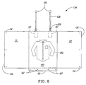
- the wrap 122 can be of any suitable size and shape.
- the wrap 122 comprises a single, preferably rectangular, panel 100.
- the dimensions of the panel 100 are such that the width will be about 30.5 cm to about 91.4 cm and the length will be about 55 cm to about 117 cm; more preferred is a width of about 40.6 cm to about 81 cm and a length of about 66 cm to about 107 cm and most preferred is a width of about 51 cm to about 71 cm and a length of about 76 cm to about 97 cm.
- the distance from the top edge of the panel 102 to the bottom edge of the panel 101 is preferably greater than the distance from the right edge of the panel 103 to the left edge of the panel 104.
- the wrap 122 preferably further comprises one or more straps 108 which are attached adjacent to the top edge of the panel 102.
- a first fastening device 109 which is fixably and permanently attached to each strap 108 so that its position on the strap does not change.
- a second fastening device 106 is preferably attached to each strap by passing the strap through the fastening device in such a way that changing its position on the strap, the length of the strap 105 can be increased or decreased.
- the first and second fastening devices cooperate to secure the flexible wrap container in a roll-like shape during use (see, e.g., Fig. 7), or a folded shape (see, e.g., Figs. 16-19).
- two pockets 110 are preferably attached adjacent to the top edge of the panel in the manner shown by Figures 1, 1A, 2 and 3. As discussed more fully hereafter, the pockets 110 can be used for storing the straps and fastening devices when they are not needed.
- the fastening devices used herein are preferably reusable mechanical fasteners. Any reusable mechanical fastener or fastening means can be used. Non-limiting examples include: fasteners wherein said first and second fastening devices, together, comprise a hook and loop (VELCRO®-type) fastener; hook fasteners such as described in U.S. Pat. No.
- fasteners wherein said first and second fastening devices, together, comprise a hook and string type fastener; fasteners wherein said first and second fastening devices, together, comprise a toggle-type fastener; fasteners wherein said first and second fastening devices, together, form a snap-type fastener-, as well as hook and eye fasteners, zipper-type fasteners, releasable buckle type fasteners as used in U.S. Pat. No. 5,330,141, to Kim, issued July 19,1994, and the like, so long as the fasteners will not cause tearing or abrasion of the garments contained inside the bag.
- a single fastening device can also be utilized with one or more straps to secure the wrap container in its rolled or folded configuration.
- the flexible wrap container may be constructed from any suitable material, including, but not limited to: woven materials, nets, scrims, and nonwoven materials.
- the structural elements or members (e.g., the strands, fibers, threads, yarns, etc.) of the wrap can also comprise any suitable material or materials. Suitable materials for these structural components of the wrap are selected from nylon, polyethylene, polypropylene, polyester, and combinations thereof.
- the structural components of the wrap 122 are coated with an acrylic material.
- the material(s) comprising the wrap can be in one or more layers. If more than one layer of material is used, the (structural components of the) layers can be comprised of the same material, or a different material. The layers may comprise the same type of structure, or a different type of structure.
- the flexible wrap is preferably constructed to have a density greater than the density of water at standard temperature and pressure so that the flexible wrap container is more likely to sink in the wash water and thus will provide better wetting and rinsing to a garment contained therein.
- the material should be flexible, yet durable enough to be used for multiple uses.
- the wrap 122 is preferably provided with a series or plurality of holes or other openings, or the wrap material should be permeable to water.
- the wrap 122 is provided with holes or openings, the size and number of openings are sufficiently large to allow water and any cleaning solution that is outside of the wrap 122 to wet the garments to be cleaned, as well as to allow dirt particles to be carried away from the garments.
- the holes or openings are preferably not so large that portions of the garments to be cleaned are overly exposed to damage in the washing machine, or are marked with the pattern of the wrap.
- the wrap 122 is flexible enough that the garments contained therein are subjected to a degree of mechanical agitation to assist in cleaning the garments, but sufficiently stiff that the wrap contains the garment and the garments will not be subjected to undue wrinkling, abrasion, and shrinkage.
- the flexibility (or stiffness) of the wrap materials described herein are measured using the Taber Stiffness measurement (ASTM D5342).
- the stiffness of the wrap material can be measured in one direction relative to the weave or knit of the wrap material, or it can be measured in two directions (such as, in the case of a square weave, in a first direction parallel to the warp yarns or, and in a second direction at a right angle thereto (e.g., parallel to the weft yarns). If the stiffness of the wrap material is measured in two directions, the Taber stiffness measured in two directions can be averaged.
- the wrap material preferably has a stiffness in one direction, as well as an average stiffness in two directions, of between about 3 and about 90 Taber stiffness units, more preferably between about 10 and about 50 Taber stiffness units.
- the lower end of the above range can also be higher than 3 Taber stiffness units.
- the lower end can be any number within the range (e.g., 4, 5, 6, ..., etc., 15, 20, 25, 30, 35, 40, 45, 50, 55, 60, 65, 70, or 75) even though the number is not specifically stated herein.
- a non-limiting example of a suitable materials for the wrap is a woven acrylic coated polyester (ACP) mesh material.
- the woven acrylic coated polyester (ACP) material is preferred because it is somewhat stiffer than the DNB material, and without wishing to be bound to any particular theory, as a result is believed to be better able to contain and keep the garments in tension in the condition/position in which they are originally placed in the wrap and reduce movement of garments inside the wrap during the washing process, while allowing water and cleaning solution easily enter through its porous structure. This has led to improvements in reducing wrinkling, abrasion, and shrinkage of the garments after washing.
- the woven acrylic coated polyester material has the desired stiffness in a structure that has very little thickness or three-dimensionality to it.
- Double Needle Bar material which is comprised of three different thread types to give it the appearance of three layers, in which each "layer” is very flexible, but when combined together into a relatively thick three-dimensional structure, has a stiffness greater than any of the "layers" alone.
- the woven acrylic coated polyester material is a single layer material with one thread type, and can, thus, be considered to be a two-dimensional material.
- the stiffness of materials used in the wrap can be varied in manners known to those skilled in the art of making such materials.
- the addition of the acrylic coating provides additional stiffness.
- modified weaving/knitting patterns and/or type of yam or thread used to weave or knit a fabric can increase or decrease the stiffness of the wrap.
- Preferred woven acrylic coated polyester materials are material numbers 961376 and 961377 obtained from Milliken & Company of Spartanburg, SC.
- the threads of these materials preferably have a diameter of between about 0.1 mm and about 0.3 mm, and more preferably have an oval cross-section with a minor diameter of about 0.14 mm and a major diameter of about 0.23 mm.
- One of these materials (961377) has square shaped openings in the weave that are approximately 1 mm x 1 mm in size.
- the total open area of this material is approximately 0.6 mm 2 /mm 2 (open area in mm 2 per square mm of material). This material is stretchable in one direction, but not in a direction at a right angle thereto.
- the other material (961376) has rectangular openings that are approximately 1.5 mm x 2 mm. This material is approximately 0.5 mm thick.
- the total open area of this material is approximately 0.7 mm 2 /mm 2 .
- the wrap can optionally be comprised of materials that reduce any potential for the wrap to absorb fugitive dyes from the garments being washed therein.
- the wrap can, for example, have a soil release polymer, or other material having this property included therein, or provided thereon in any suitable manner.
- a soil release polymer of the type described herein may be coated on the structural elements comprising the wrap (e.g., the yarns).
- a soil release polymer can be incorporated into the material comprising the structural elements of the wrap prior to or during the formation of those structural elements.
- a soil release polymer can be incorporated into any coating that is provided on the structural elements of the wrap (e.g., the soil release elements can be incorporated into the acrylic coating). Providing the wrap with such materials will reduce the potential for the wrap to absorb fugitive dyes and change color, and help assure the user of the wrap that the wrap is not removing dyes from the garments being washed, or transferring such dyes to other garments.
- the wrap is used in the present invention.
- a garment 120 is placed on the panel portion of the wrap 100 with suitable care exercised so that no part of a garment is outside the dimensions of the panel.
- the wrap may in one embodiment then be rolled, starting at the bottom edge of the panel 101, as one would roll a sleeping bag for storage purposes after being used.
- the wrap should not be so tightly rolled that the garment inside might be subject to excessive wrinkling.
- the wrap 122 should be in the spiral shape as illustrated by Figure 7. As seen in Figure 7, the length of each strap has been adjusted so that when the first and second fastening devices are engaged, the straps are tightly securing the rolled wrap.
- the wrap may be folded rather than rolled.
- Figs. 16 to 19 show a non-limiting embodiment of a folded wrap where the wrap is folded twice to form a four layer structure.
- the wrap may be folded in any other suitable manner.
- the wrap can be folded in half, or the wrap may be folded into a three or more layer structure. Folding the wrap instead of rolling it may, in some washing machines (especially Japanese washing machines) tend to reduce the wrinkling of the garments after washing.
- Located adjacent to the bottom edge of the panel are at least two, preferably at least four, connecting means 107 which in a preferred embodiment are snap-type buttons.
- the wraps are constructed in such a way that an enlarged wrap 125 may be constructed by attaching two wraps to each other via the connecting means 107 located adjacent to the bottom edge of each panel. This construction can be seen in Figure 2. When the wraps are so connected, the panel of one wrap partially overlaps the panel of the other wrap as can be seen in Figure 2.
- An enlarged wrap 125 can accommodate larger garments (such as a dress 121) than a single wrap 122.
- the wrap further consists of two flaps 111,112.
- the flaps are attached to the panel along the right edge of the panel 103 and along the left edge of the panel 104.
- Each flap has a surface area of from about 1 ⁇ 2 to 1 times the surface area of the panel to which it is attached. So when the flaps are folded inwardly and laid on top of the panel area, they completely cover the panel, essentially adding a second panel layer to the wrap.
- each flap has a mating sinusoidal design.
- the mating sinusoidal shape contributes to the overall integrity of the rolled wrap by fitting the two flaps 111, 112 more securely to each other than if the flaps had a conventional rectangular shape, and is believed to reduce the buckling of the wrap and wrinkling of the garments contained therein.
- Figure 1A shows these two flaps: one being folded out 111 and one being folded over the panel 112.
- the flaps 111, 112 and the panel 100 are also equipped with attaching devices 114 which are located adjacent to the top edge of the panel 102. When attached to each other these attaching devices secure the flaps to the panel 100.
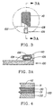
- the wrap is constructed from four different layers as is shown in Figure 4. These four layers provide a significant amount of cushioning to the delicate garments which may be placed inside.
- the panel 100 is a layered material, comprising a core material 131 between a first layer material 130 and a second layer material 132, the core material being polyester, the first layer material and the second layer material being nylon and the first flap and second flap each constructed from polyester.
- the second layer material of nylon and the polyester material that forms the flaps are woven in such a way that they are provided with numerous small holes or pores through which water may pass either into or out of the interior of the rolled wrap while the second layer material does not have any such holes but is water permeable.
- the preferred flexible wrap container When the preferred flexible wrap container is used, it may contain two garments: one placed directly on top of the panel and the other placed on top of the flaps after they are folded across the garment on the panel.
- the flexible wrap container 134 comprises the flexible panel 100 and a first flap 111 and a second flap 112.
- the first and second flaps 111 and 112 each preferably have a width about equal to the width of the flexible panel 100. More preferably, the first and second flaps 111 and 112 have a width between about 40 cm and about 70 cm for a flexible panel 100 having a width between about 45 cm and about 72 cm.
- the first flap 111 preferably extends adjacent to the right edge of the panel 100 when the first flap 111 is folded about the left edge of the panel 100 and the second flap 112 preferably overlaps the first flap 111 when folded about the right edge of the panel 100 and extends adjacent to the left edge of the panel 100.
- the flexible panel 100 and the first and second flaps 111 and 112 can be provided as separate structures and attached to the flexible panel 100 or the flexible panel 100 and the flaps 111 and 112 can be formed from a unitary material. While the distal or unattached edges 136 of the flaps 111 and 112 are illustrated as straight, other edge configurations, such as the previously described sinusoidal shape, can be provided.
- any suitable number of attaching devices 114 can be provided along one or more of the distal edges 136 of the flaps 111 and 112 to secure the flaps to each other and/or the flexible panel 100.
- the overlapping flaps 111 and 112 deliver several benefits.
- the increased width of the flaps 111 and 112 moves the distal edges 136 of the overlapping flaps 111 and 112 toward the right and left edges of the panel 100 and away from contact with the garment 120. This can reduce the likelihood that seams or stitching of the distal edges 136 will leave an impression upon the garment 120 during use of the flexible wrap container 134.
- the overlapping flaps 111 and 112 provide an additional layer of protection for the garment 120 and can reduce the risk that portions of the garment 120 will "escape" from the flexible wrap container 134.
- Overlapping flaps 111 and 112 also provide a flexible wrap container which can accommodate more than one garment.
- the flaps 111 and 212 are extended to expose the flexible panel 100, as shown in Fig. 8.
- the garment 120 is placed over the flexible panel 100 and one of the flaps 111 or 112 is folded over the garment 120 as shown in Fig. 10 (flap 111 being illustrated as folded over the garment).
- Garment 138 is then placed over the folded flap (e.g., flap 111) and the remaining flap (e.g., flap 112) is folded over the garment 138 and secured using the attaching devices 114, if provided.
- the flexible wrap container 134 is then rolled and secured using the first and second fastening devices 106 and 109.
- the width of the overlapping flaps 111 and 112 is discussed herein as preferably extending to adjacent the right and left edges of the panel 100, the width of the overlapping flaps 111 and 112 is preferably between about one half and the full width of the panel 100.
- a single flap having a width equal to about the width of the panel 100 can be provided in place of the two overlapping flaps 111 and 112.
- Such an embodiment would preferably include attaching devices 114 to secure the single flap to the flexible panel.
- the flexible wrap container 140 comprises a flexible panel 100 having a body 142 with a right edge, left edge, and a bottom edge.
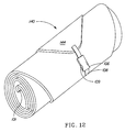
- the flexible panel 100 also has a tapered top portion 144 which is attached to the body 142.
- the top portion 144 has an apex 146 which is located at about the mid-point of the body 142.
- the length of the tapered top portion 144 is preferably at least about one half of the length of the body 142. More preferably, the length of the top portion 144 is between about 40 cm and about 50 cm for a body having a length between about 75 cm and about 80 cm.
- a single strap 108 is attached adjacent the apex 146 of the top portion 144.
- a first fastening device 109 At an end of the strap is a first fastening device 109 which is fixably and permanently attached to the strap 108 so that its position on the strap does not change.
- a second fastening device 106 is attached to the strap as previously discussed.
- the inwardly tapering top portion 144 and/or provision of a single strap 106 adjacent its apex 146 can provide several surprising benefits during use of the flexible wrap container 140.
- the tapered top portion 144 when rolled about the body 142 during use, as shown in Fig. 12, imparts additional structure to the rolled flexible wrap container 140 by virtue of spiral layers 144 which encircle the body 142 when rolled. This additional structure assists in retaining the roll-like shape of the flexible wrap container 140 such that garments stored within the wrap require less finishing as the flexible wrap container 140 has a reduced tendency to twist or unroll from washing machine agitation.
- the flexible wrap container 140 with its a centrally located strap 108 in combination with the tapered top portion 144 also better resists the formation of gaps between layers of the rolled wrap container through which portions of a garment 120, such as sleeves or a neck, can be extracted during washing machine agitation. While the tapered top portion 140 or 144 illustrated herein is preferred, other top portions can be provided in accordance with the present invention. For example, the top portion 144 may displaced from the right and/or left edges of the body 142 or be provided with a larger apex or less of a taper.
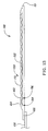
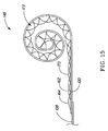
- the flexible wrap container 148 has a flexible panel 100 with a right edge, left edge, and bottom edge. Disposed adjacent each of the right and left edges of the panel 100 is a fence 150.
- the fences 150 can be provided in place of the previously described flaps for retaining a garment within a flexible wrap container.
- the fences 150 can be formed from a plurality of loops 152 whose ends 154 and 156 are attached to the flexible panel 100.
- the loops 152 can be formed from polyester filaments, or a similar material, and attached to the flexible panel 100 by stitching, heat sealing, hot glue, cold glue, ultrasonic welding, etc.
- the loops 152 are preferably formed into a first row 158, wherein the loops 152 of the first row are disposed end to end, and a second row 160, wherein the end of the loops are also disposed substantially end to end.
- the first loop 162 of the second row 160 begins at about the mid-point of the first loop 164 of the first row 158, as shown in Fig. 13, and the opposite end of the first loop 162 of the second row 160 terminates at about the mid-point of second loop 170 of the first row 158, although the beginning location of the second row can be varied.
- the loops preferably lay substantially flat when the flexible wrap container is unrolled and are flexible enough to rise away from the flexible panel 100 such that loops from the first and second rows 158 and 160 will overlap to form the open fence 150 having openings 172, as best seen in Fig. 14, through which wash water can flow but which are small enough such that the garment is unable to exit the flexible container wrap 148 during use.
- the filaments forming the loops preferably have a gauge between about 0.25 mm and about 3.175 mm and the opening 172 have an open area between about 1.5 cm 2 and about 4.8 cm 2 .
- first and second rows 158 and 160 are described herein as distinct rows, it will be understood that a single row can be provided in place of two rows or that more that two rows can be used. Further, it will be appreciated that the gauge and spacing of the loops can be changed to achieve differing degrees of flexibility in the longitudinal direction and garment containment in the transverse direction. Further the longitudinal length of the fences 150 can be varied, although it is preferred that the length extend from adjacent to the top edge of the panel 100 to adjacent to the bottom edge of the panel 100.
- the rolled or folded wrap can be placed in the washing machine in any suitable manner.
- the wrap is typically placed in a U.S. machine by bending it slightly to fit it around the agitator before the machine is turned on.
- the wrap can be placed in the washing machine without any special means to retain it in place.
- a suitable retaining device can be used to retain the wrap in a particular position in the tub of the washing machine.
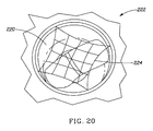
- a retaining device such as a net 224 can be placed over the wrap to keep the wrap submerged and prevent the wrap from floating during the washing process. This will ensure that the garments contained in the wrap will be adequately wetted, and more completely cleaned.
- This is a particularly useful variation in the case of the mild wash conditions and short wash times in washing machines used in Japan where the water is circulated mainly horizontally by a disk at the bottom of the wash tub. These machines differ from U.S. machines where the water moves in a vertical circular motion which tends to pull the wrap down toward the bottom of the wash tub.
- a net 224 is used which extends across the interior of the tub of the washing machine, and is disposed over the wrap.
- the net can be stretchable or non-stretchaote.
- the net can be of any suitable size.
- the net may, for example, have a diagonal dimension of between 20-40 cm in an unstretched condition.
- the net can be of any suitable shape, including, but not limited to: square, rectangular, triangular, and circular.
- the net can be made of any suitable material.
- the net should be pervious so that it does not disturb the water flow in the washing machine.
- the net is a Stretchable elastic material which has a square configuration and is 22 cm x 22 cm in an unstretched condition- This net has sixteen square-shaped apertures, each of which is approximately 5 cm x 5 cm.
- the net can be held in place in any suitable manner.
- the net is held in place by four metal hooks that engage with the holes in the inside of the tub of the washing machine.
- the net is not limited to being retained by four hooks. Any suitable number of hooks (including between 3-10 hooks) will do.
- the hooks can be made of plastic, or any other suitable material.
- the net may be held in place by types of devices other than metal hooks. A few non-limiting examples of suitable devices for holding the net in place include: suction cups, magnets, and stickers.
- the retaining device can comprise some other suitable device other than a net. Any device that retains the wrap in place in the washing machine will be suitable.
- the wrap could, for example, be hooked to the tub with straps. Alternatively, the wrap could be weighted to keep it submerged.
- the wrap can provided with magnets which can be attached to the interior of the wash tub to keep the same in position.
- the garment container resists shrinkage of the garments contained therein such that the garments have a shrinkage ratio (% dimensional change) of less than or equal to about 15% (e.g., between about 0% and about 15%) over five wash cycles.
- the shrinkage ratio (% dimensional change) is measured according to the Entire Garment Shrinkage Test Method described in the Test Methods section below.
- the garment container preferably has a wetting effectiveness of the garments contained therein of between about 90% and about 100%, more preferably at least about 95%, and most preferably 100%.
- the wetting effectiveness of the garments is measured according to the Wetting Test Method described in the Test Methods section below.
- the flexible wrap container disclosed by the present invention provides significant benefits over similar devices in use today. In particular, it offers a superior means for securing and closing itself, thereby limiting the chance that garments will spill out of it and be damaged while being laundered in a washing machine. Additionally, the flexible wrap container insulates and protects the garment or garments contained therein from the stress and abrasion that may be caused by the agitator and other internal parts of a washing machine.
- the flexible wrap container further offers an expandability and versatility that is not seen in other such devices: not only is the flexible wrap container larger than competing devices, it has a series of connecting means (e.g. snaps) which allow two identical flexible wrap containers to be snapped together to provide an additional flexible wrap container of twice the original capacity of the flexible wrap container. This further enhances the dimension retention benefits of the present invention.
- This procedure is for preparing and evaluating entire garments for measuring fabric shrinkage.
- DC Dimensional Change
- Shrinkage - a dimensional change resulting in a decrease in length or width of the fabric specimen.
- This procedure is used for preparing and evaluating swatches for measuring fabric shrinkage.
- DC Dimensional Change
- Shrinkage - a dimensional change resulting in a decrease in length or width of the fabric specimen.
- the test used to measure stiffness is the Taber tester (ASTM D5342).
- the samples of material are measured in two directions - parallel to the warp yarns and perpendicular thereto (parallel to the weft yarns).
- the Taber Stiffness is measured on four samples of material for each direction measured.
Landscapes
- Chemical & Material Sciences (AREA)
- Engineering & Computer Science (AREA)
- Life Sciences & Earth Sciences (AREA)
- Chemical Kinetics & Catalysis (AREA)
- Oil, Petroleum & Natural Gas (AREA)
- Wood Science & Technology (AREA)
- Organic Chemistry (AREA)
- Textile Engineering (AREA)
- Health & Medical Sciences (AREA)
- Emergency Medicine (AREA)
- Detergent Compositions (AREA)
- Accessory Of Washing/Drying Machine, Commercial Washing/Drying Machine, Other Washing/Drying Machine (AREA)
Description
- This application claims the benefit of U.S. Provisional Application Nos. 60/105,539, filed October 24, 1998; and 60/157,082 and 60/157,399, filed October 1, 1999, PCT applications PCT/US99/24937 and PCT/US99/24938, both filed October 22, 1999, and U.S. Patent Application No. (to be assigned), filed August 25, 2000.
- The present invention relates to products and processes for laundering delicate or dry-clean only garments in a washing machine.
- Perhaps the most widely practiced aqueous laundering process is that which the consumer performs when she or he immerses a garment into an aqueous laundry detergent solution in a conventional home washing machine. Such a process has long been shown to provide excellent performance for both stain removal and overall garment cleaning and can be performed without using hazardous or toxic chemicals. Moreover, the use of an aqueous laundering process in a conventional washing machine is considerably more convenient and inexpensive than virtually any other laundering method.
- Nonetheless, such processes can produce unacceptable results when applied to a broad range of delicate or dry-clean only garments, such as those made from wool. Wool, is made up of fibers which can interlock with one another by a series of "scales". Generally, these interlocking scales cannot move past one another and as a result wool is a relatively strong textile. However, when wool becomes wet or moistened, the fibers move together, and the wool garment shrinks. This shrinkage cannot be undone because these "scales" can only move past one another in a preferred direction. Sufficient force cannot be exerted to move them in the direction opposite to the preferred direction to undo the shrinkage. Thus when the wool garment is removed from the aqueous laundry process, shrinkage has occurred and the garment is irreversibly damaged. Similarly, rayon, when saturated with water, becomes extremely weak and the subsequent agitation and abrasion that it experiences in a typical aqueous laundry process is likely not only to cause severe damage to the garment but also to leave it extremely wrinkled. Similarly, delicate fabrics like silk will not only be severely wrinkled but also may lose their desirable soft feel.
- Garments such as sift are also vulnerable not only to the mechanical agitation of a conventional washing machine but are also particularly vulnerable to the typical laundry detergents because such detergents may contain ingredients that are too harsh for such delicate fabrics. It is thus desirable to provide an aqueous laundering process adapted for use in a conventional washing machine that is not harmful to garments made from fabrics such as wool, leather, suede, rayon, silk, acrylics, triacetates, fine cottons and blends of these aforementioned: materials.
- Therefore, a need exists for a process for laundering delicate or dry-clean only garments in a washing machine without the deleterious consequences described above. A need also exists for a convenient, inexpensive, and efficacious way to clean delicate and dry-clean only garments in the home.
- Garment contains from use in laundering processes are disclosed in DE-A-2547588; WO 97/07278; WO 97/27354; DE19939006; US5746514 and AT190887.
- The present invention solves the long-standing need for an inexpensive and convenient process of cleaning dry-clean only and other delicate garments in an aqueous laundering process, such as a conventional home washing machine. Processes (or systems) and kits for performing these processes have been found by which delicate and 4ry-clem only garments can be cleaned and freshened in an aqueous laundering process without damaging the garments.
- The garment container, according to
claim 1 is designed to contain and protect delicate or dry-clan only clothes from being subjected to the agitation action of a washing machine. In one non-limiting embodiment, the basic part of the flexible wrap container is a flexible rectangular panel constructed of an open weave material, such as polyethylene, polypropylene, polyester or nylon material, either of which is coated with an acrylic coating. The garment container resists shrinkage of the garments contained therein such that the garments have a shrinkage ratio (% dimensional change) of less than or equal to about 15% (e.g., between about 0% and about 15%) over five wash cycles. The garment container has a wetting effectiveness of the garments contained therein of between about 90% and about 100%, preferably at least about 95%, and most preferably 100%. - In a preferred embodiment, the flexible wrap container additionally comprises a first and second flap attached along the right edge of the panel and along the left edge of the panel, respectively. The flaps may overlap each other to provide increased garment containment during use. The flexible wrap container is provided with closure devices, such as one or more Straps. If straps are provided, each strap is equipped with a pair of fasteners. When the wrap is folded up according to the directions of use, the strap or straps may be tightened around the wrap and one or more fasteners engaged to hold the strap or straps in place so that the bag is secured and will not open up under normal agitation conditions. Other preferred flexible wrap containers are provided with a tapering top portion to which is attached at least one of the previously described straps to further aid in containment of the garment. In a version of these embodiments, optionally at least two and preferably four snaps are located near the edge of one of the panel's sides or ends. These snaps may be used for attaching die flexible wrap container to another identical flexible wrap container to increase the capacity of the flexible wrap container, or to permit larger size garments to be placed therein.
-
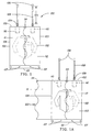
- Figure 1 is a side view illustrating the
flexible wrap container 122. - Figure 1A is a side view illustrating the
flexible wrap container 122 and showing two attached flaps, a first flap 111 being folded out and asecond flap 112 being folded over the panel. - Figure 2 is a side view illustrating an enlarged
flexible wrap container 125. In this embodiment, the two wraps can be attached to each other via connectingmeans 107 located adjacent to the bottom edge of thepanel 101 of eachflexible wrap container 122 to form an enlargedflexible wrap container 125. - Figure 3 is a detail illustrating a
pocket 110 attached to the panel of the flexible wrap container which provides a storage area for the extra straps and fastening devices when two flexible wrap containers are attached to form an enlarged flexible wrap container as in Figure 2. - Figure 3A is a sectional side view of the
pocket 110 illustrating the storing of straps and fastening devices in the attached pockets when two flexible wrap containers are attached to form an enlarged flexible wrap container as in Figure 2 - Figure 4 is an enlarged sectional view showing a profile of the material layers in a preferred embodiment of the
flexible wrap container 122. - Figure 5 is a perspective of the
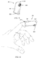
wash pretreatment applicator 310 which is used in the present invention to pre-treat stains using hand pressure. - Figure 6 is a perspective of the
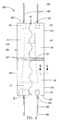
wash pretreatment applicator 310 as positioned on a human finger. - Figure 7 is a perspective of the
flexible wrap container 122 in a roll-like shape. - Figure 8 is a top planar view of a preferred flexible wrap container made in accordance with the present invention, wherein overlapping first and second flaps which are illustrated in an open position.
- Figure 9 is a top planar view of the flexible wrap container of Fig. 8, wherein the first and second flaps have been folded over the right and left edges of the panel of the flexible wrap container.
- Figure 10 is a top planar view of the flexible wrap container of Fig. 8, where the first flap has been folded over the left edge of the panel to illustrate placement of a second garment in the flexible wrap container.
- Figure 11 is a top planar view of another flexible wrap container made in accordance with the present invention, wherein a tapered top portion is provided.
- Figure 12 is a perspective view of the flexible wrap container of Fig. 11, wherein the flexible wrap container is illustrated in a roll-like shape.
- Figure 13 is a side elevation view of yet another flexible wrap container made in accordance with the present invention, wherein a fence is provided along the edge of the flexible wrap container.
- Figure 14 is a top planar view of the flexible wrap container of Fig. 13.
- Fig. 15 is a side elevational view of the flexible wrap container of Fig. 13, wherein the flexible wrap container is illustrated in a roll-like shape.
- Figure 16 is a perspective view of a wrap similar to that shown in Fig. 11 with the flaps folded over.
- Figure 17 is a perspective view of the wrap shown in Fig. 16 which has been folded once.
- Figure 18 is a perspective view of the wrap shown in Fig. 16 which has been folded twice.
- Figure 19 is a perspective view of the wrap similar shown in Fig. 16 with the strap fastened around the folded wrap.
- Figure 20 is a perspective view showing the interior of the tub of a washing machine with a net therein to hold the folded flexible wrap container in position.
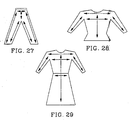
- Figure 27 is a schematic view showing the garment benchmark locations for a pair of pants or trousers for the entire garment shrinkage test method.
- Figure 28 is a schematic view showing the garment benchmark locations for blouses, shirts, and sweaters.
- Figure 29 is a schematic view showing the garment benchmark locations for dresses and skirts.
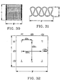
- Figure 30 is a plan view of an example of a woven fabric swatch.
- Figure 31 is an enlarged plan view of a yam as it would appear in a knit fabric swatch.
- Figure 32 is a plan view of the swatch marking template for the Fabric Swatch Shrinkage Test Method.
- Reference will now be made in detail to the present preferred embodiments of the invention, non-limiting examples of which are illustrated in the accompanying drawings.
- The present invention relates to articles by which delicate and dry-clean only garments can be cleaned and freshened in an aqueous laundering process without damaging the garment. The article is a garment container, which is preferably in the form of a flexible, pervious wrap. When a garment is secured within this container, the garment is buffered and cushioned from the force and stress caused by the washing machine. The garment container also helps to control shrinkage of the garment. Definitions that are applicable to the present description are as follows.
- By "aqueous compositions" herein is meant compositions which comprise a major portion of water.
- By "solution" herein is meant a liquid mixture of ingredients. As used herein "solution" does not convey or imply the existence of only a single liquid or solid phase. Nor is it meant to describe a homogenous solvent/solute system.
- By "effective amount" herein is meant any amount capable of measurably improving stain removal from a localized area of a garment. In general, this amount may vary quite widely.
- By "cleaning" herein is meant the removal of soils and stains from fabrics. By "contact with stained areas" with respect to the wash pretreatment applicators is meant contact which is afforded by the applicator portion of the device with the one side of the stained area. By "contact with the stained areas" with respect to the absorbent stain receiver pad is meant that the side of the stained area of the fabric opposite the wash pretreatment applicator directly contacts the receiver pad and is in close communication therewith. Thick garments may require a modified process (e.g., the stain will be removed from the same side that the pretreatment applicator contacts.
- All percentages, ratios and proportions herein are by weight, unless otherwise specified.
- The components of the processes or systems of this invention and kits for performing these processes and their method of use are described in more detail hereinafter.
- The action of the agitator in a clothes washer has long been known to expose delicate fabrics to sufficient abrasion and stress that severe damage can occur as a result. As a result, bags have been developed which can be used in a washing machine to protect these garments from abrasion and stress. Nonetheless these have proved unsatisfactory for a variety of reasons. First, they are generally too small to contain anything but one or two small garments-and even then may bunch-up the garments and exacerbate wrinkling and shape loss. Second, many of these bags do not have a reliable closure means, and so the bag often comes open during washing, depriving the garments of the protection the bag is supposed to provide and likely increasing the abrasion and wear on the garments. Third, these bags are often constructed to have an outer shell made of a grid-like netting which allows contact between the wash liquor and the garment to provide cleaning benefits; but this grid-like pattern can also leave an identical grid impression on the garments contained inside. Such a pattern may be difficult to iron out.
- One embodiment of flexible wrap container ("wrap") made in accordance with the present invention which remedies many of these problems is shown in Figures 1, 1A and 2. The
wrap 122 can be of any suitable size and shape. In the embodiment shown in Figures 1, 1A, and 2, thewrap 122 comprises a single, preferably rectangular,panel 100. The dimensions of thepanel 100 are such that the width will be about 30.5 cm to about 91.4 cm and the length will be about 55 cm to about 117 cm; more preferred is a width of about 40.6 cm to about 81 cm and a length of about 66 cm to about 107 cm and most preferred is a width of about 51 cm to about 71 cm and a length of about 76 cm to about 97 cm. In a rectangular embodiment as depicted in Figure 1, the distance from the top edge of thepanel 102 to the bottom edge of thepanel 101 is preferably greater than the distance from the right edge of thepanel 103 to the left edge of thepanel 104. - The
wrap 122 preferably further comprises one ormore straps 108 which are attached adjacent to the top edge of thepanel 102. At an end of each strap is afirst fastening device 109 which is fixably and permanently attached to eachstrap 108 so that its position on the strap does not change. Asecond fastening device 106 is preferably attached to each strap by passing the strap through the fastening device in such a way that changing its position on the strap, the length of thestrap 105 can be increased or decreased. The first and second fastening devices cooperate to secure the flexible wrap container in a roll-like shape during use (see, e.g., Fig. 7), or a folded shape (see, e.g., Figs. 16-19). Additionally, twopockets 110 are preferably attached adjacent to the top edge of the panel in the manner shown by Figures 1, 1A, 2 and 3. As discussed more fully hereafter, thepockets 110 can be used for storing the straps and fastening devices when they are not needed. - The fastening devices used herein are preferably reusable mechanical fasteners. Any reusable mechanical fastener or fastening means can be used. Non-limiting examples include: fasteners wherein said first and second fastening devices, together, comprise a hook and loop (VELCRO®-type) fastener; hook fasteners such as described in U.S. Pat. No. 5,058,247 to Thomas & Blaney issued October 22,1991; fasteners wherein said first and second fastening devices, together, comprise a hook and string type fastener; fasteners wherein said first and second fastening devices, together, comprise a toggle-type fastener; fasteners wherein said first and second fastening devices, together, form a snap-type fastener-, as well as hook and eye fasteners, zipper-type fasteners, releasable buckle type fasteners as used in U.S. Pat. No. 5,330,141, to Kim, issued July 19,1994, and the like, so long as the fasteners will not cause tearing or abrasion of the garments contained inside the bag. As will be apparent, a single fastening device can also be utilized with one or more straps to secure the wrap container in its rolled or folded configuration.
- The flexible wrap container may be constructed from any suitable material, including, but not limited to: woven materials, nets, scrims, and nonwoven materials. The structural elements or members (e.g., the strands, fibers, threads, yarns, etc.) of the wrap can also comprise any suitable material or materials. Suitable materials for these structural components of the wrap are selected from nylon, polyethylene, polypropylene, polyester, and combinations thereof. The structural components of the
wrap 122 are coated with an acrylic material. The material(s) comprising the wrap can be in one or more layers. If more than one layer of material is used, the (structural components of the) layers can be comprised of the same material, or a different material. The layers may comprise the same type of structure, or a different type of structure. If more than one layer of material is used, the layers can be joined together directly or indirectly by any known method of joining known. The flexible wrap is preferably constructed to have a density greater than the density of water at standard temperature and pressure so that the flexible wrap container is more likely to sink in the wash water and thus will provide better wetting and rinsing to a garment contained therein. The material should be flexible, yet durable enough to be used for multiple uses. To ensure that water can easily penetrate through the wrap material to contact the articles of clothing contained inside, thewrap 122 is preferably provided with a series or plurality of holes or other openings, or the wrap material should be permeable to water. - The
wrap 122 is provided with holes or openings, the size and number of openings are sufficiently large to allow water and any cleaning solution that is outside of thewrap 122 to wet the garments to be cleaned, as well as to allow dirt particles to be carried away from the garments. The holes or openings, are preferably not so large that portions of the garments to be cleaned are overly exposed to damage in the washing machine, or are marked with the pattern of the wrap. - The
wrap 122 is flexible enough that the garments contained therein are subjected to a degree of mechanical agitation to assist in cleaning the garments, but sufficiently stiff that the wrap contains the garment and the garments will not be subjected to undue wrinkling, abrasion, and shrinkage. - The flexibility (or stiffness) of the wrap materials described herein are measured using the Taber Stiffness measurement (ASTM D5342). The stiffness of the wrap material can be measured in one direction relative to the weave or knit of the wrap material, or it can be measured in two directions (such as, in the case of a square weave, in a first direction parallel to the warp yarns or, and in a second direction at a right angle thereto (e.g., parallel to the weft yarns). If the stiffness of the wrap material is measured in two directions, the Taber stiffness measured in two directions can be averaged. The wrap material preferably has a stiffness in one direction, as well as an average stiffness in two directions, of between about 3 and about 90 Taber stiffness units, more preferably between about 10 and about 50 Taber stiffness units. The lower end of the above range can also be higher than 3 Taber stiffness units. For example, the lower end can be any number within the range (e.g., 4, 5, 6, ..., etc., 15, 20, 25, 30, 35, 40, 45, 50, 55, 60, 65, 70, or 75) even though the number is not specifically stated herein.
- A non-limiting example of a suitable materials for the wrap is a woven acrylic coated polyester (ACP) mesh material.
- The woven acrylic coated polyester (ACP) material is preferred because it is somewhat stiffer than the DNB material, and without wishing to be bound to any particular theory, as a result is believed to be better able to contain and keep the garments in tension in the condition/position in which they are originally placed in the wrap and reduce movement of garments inside the wrap during the washing process, while allowing water and cleaning solution easily enter through its porous structure. This has led to improvements in reducing wrinkling, abrasion, and shrinkage of the garments after washing. The woven acrylic coated polyester material has the desired stiffness in a structure that has very little thickness or three-dimensionality to it. This is in contrast to the Double Needle Bar material, which is comprised of three different thread types to give it the appearance of three layers, in which each "layer" is very flexible, but when combined together into a relatively thick three-dimensional structure, has a stiffness greater than any of the "layers" alone. The woven acrylic coated polyester material is a single layer material with one thread type, and can, thus, be considered to be a two-dimensional material.
- The stiffness of materials used in the wrap can be varied in manners known to those skilled in the art of making such materials. For example, the addition of the acrylic coating provides additional stiffness. In addition, modified weaving/knitting patterns and/or type of yam or thread used to weave or knit a fabric can increase or decrease the stiffness of the wrap.
- Preferred woven acrylic coated polyester materials are material numbers 961376 and 961377 obtained from Milliken & Company of Spartanburg, SC. The threads of these materials preferably have a diameter of between about 0.1 mm and about 0.3 mm, and more preferably have an oval cross-section with a minor diameter of about 0.14 mm and a major diameter of about 0.23 mm. One of these materials (961377) has square shaped openings in the weave that are approximately 1 mm x 1 mm in size. The total open area of this material is approximately 0.6 mm2/mm2 (open area in mm2 per square mm of material). This material is stretchable in one direction, but not in a direction at a right angle thereto. The other material (961376) has rectangular openings that are approximately 1.5 mm x 2 mm. This material is approximately 0.5 mm thick. The total open area of this material is approximately 0.7 mm2/mm2.
- The wrap can optionally be comprised of materials that reduce any potential for the wrap to absorb fugitive dyes from the garments being washed therein. The wrap can, for example, have a soil release polymer, or other material having this property included therein, or provided thereon in any suitable manner. For instance, a soil release polymer of the type described herein may be coated on the structural elements comprising the wrap (e.g., the yarns). In another non-limiting- example, a soil release polymer can be incorporated into the material comprising the structural elements of the wrap prior to or during the formation of those structural elements. In still another example, a soil release polymer can be incorporated into any coating that is provided on the structural elements of the wrap (e.g., the soil release elements can be incorporated into the acrylic coating). Providing the wrap with such materials will reduce the potential for the wrap to absorb fugitive dyes and change color, and help assure the user of the wrap that the wrap is not removing dyes from the garments being washed, or transferring such dyes to other garments.
- The manner in which the wrap is used in the present invention is straightforward. A
garment 120 is placed on the panel portion of thewrap 100 with suitable care exercised so that no part of a garment is outside the dimensions of the panel. After placing the garment on the panel, the wrap may in one embodiment then be rolled, starting at the bottom edge of thepanel 101, as one would roll a sleeping bag for storage purposes after being used. The wrap should not be so tightly rolled that the garment inside might be subject to excessive wrinkling. When rolling is completed thewrap 122 should be in the spiral shape as illustrated by Figure 7. As seen in Figure 7, the length of each strap has been adjusted so that when the first and second fastening devices are engaged, the straps are tightly securing the rolled wrap. - Alternatively, the wrap may be folded rather than rolled. Figs. 16 to 19 show a non-limiting embodiment of a folded wrap where the wrap is folded twice to form a four layer structure. The wrap may be folded in any other suitable manner. For example, the wrap can be folded in half, or the wrap may be folded into a three or more layer structure. Folding the wrap instead of rolling it may, in some washing machines (especially Japanese washing machines) tend to reduce the wrinkling of the garments after washing.
- Located adjacent to the bottom edge of the panel are at least two, preferably at least four, connecting means 107 which in a preferred embodiment are snap-type buttons. The wraps are constructed in such a way that an
enlarged wrap 125 may be constructed by attaching two wraps to each other via the connecting means 107 located adjacent to the bottom edge of each panel. This construction can be seen in Figure 2. When the wraps are so connected, the panel of one wrap partially overlaps the panel of the other wrap as can be seen in Figure 2. Anenlarged wrap 125 can accommodate larger garments (such as a dress 121) than asingle wrap 122. - When two wraps are attached to each other via the connecting means 107 located adjacent to the bottom edge of each panel as in the alternate embodiment depicted in Figure 2, there are an extra set of
straps 108 and first andsecond fastening devices pocket 110. - In a preferred embodiment, the wrap further consists of two flaps 111,112. The flaps are attached to the panel along the right edge of the
panel 103 and along the left edge of thepanel 104. Each flap has a surface area of from about ½ to 1 times the surface area of the panel to which it is attached. So when the flaps are folded inwardly and laid on top of the panel area, they completely cover the panel, essentially adding a second panel layer to the wrap. In the embodiment shown in Figures 1, 1A and 2, each flap has a mating sinusoidal design. The mating sinusoidal shape contributes to the overall integrity of the rolled wrap by fitting the twoflaps 111, 112 more securely to each other than if the flaps had a conventional rectangular shape, and is believed to reduce the buckling of the wrap and wrinkling of the garments contained therein. Figure 1A shows these two flaps: one being folded out 111 and one being folded over thepanel 112. Theflaps 111, 112 and thepanel 100 are also equipped with attachingdevices 114 which are located adjacent to the top edge of thepanel 102. When attached to each other these attaching devices secure the flaps to thepanel 100. - In one embodiment of the present invention the wrap is constructed from four different layers as is shown in Figure 4. These four layers provide a significant amount of cushioning to the delicate garments which may be placed inside. The
panel 100 is a layered material, comprising acore material 131 between afirst layer material 130 and asecond layer material 132, the core material being polyester, the first layer material and the second layer material being nylon and the first flap and second flap each constructed from polyester. Optionally, the second layer material of nylon and the polyester material that forms the flaps are woven in such a way that they are provided with numerous small holes or pores through which water may pass either into or out of the interior of the rolled wrap while the second layer material does not have any such holes but is water permeable. - When the preferred flexible wrap container is used, it may contain two garments: one placed directly on top of the panel and the other placed on top of the flaps after they are folded across the garment on the panel.
- Referring to Figs. 8 and 9, another preferred flexible wrap container made in accordance with the present invention is illustrated. The
flexible wrap container 134 comprises theflexible panel 100 and a first flap 111 and asecond flap 112. The first andsecond flaps 111 and 112 each preferably have a width about equal to the width of theflexible panel 100. More preferably, the first andsecond flaps 111 and 112 have a width between about 40 cm and about 70 cm for aflexible panel 100 having a width between about 45 cm and about 72 cm. In other words, the first flap 111 preferably extends adjacent to the right edge of thepanel 100 when the first flap 111 is folded about the left edge of thepanel 100 and thesecond flap 112 preferably overlaps the first flap 111 when folded about the right edge of thepanel 100 and extends adjacent to the left edge of thepanel 100. Theflexible panel 100 and the first andsecond flaps 111 and 112 can be provided as separate structures and attached to theflexible panel 100 or theflexible panel 100 and theflaps 111 and 112 can be formed from a unitary material. While the distal orunattached edges 136 of theflaps 111 and 112 are illustrated as straight, other edge configurations, such as the previously described sinusoidal shape, can be provided. Further, any suitable number of attaching devices 114 (e.g., snaps, hook and loop fasteners, magnetic fasteners, etc.) can be provided along one or more of thedistal edges 136 of theflaps 111 and 112 to secure the flaps to each other and/or theflexible panel 100. - Referring still to Figures 8 and 9, the overlapping
flaps 111 and 112 deliver several benefits. For example, the increased width of theflaps 111 and 112 moves thedistal edges 136 of the overlappingflaps 111 and 112 toward the right and left edges of thepanel 100 and away from contact with thegarment 120. This can reduce the likelihood that seams or stitching of thedistal edges 136 will leave an impression upon thegarment 120 during use of theflexible wrap container 134. The overlappingflaps 111 and 112 provide an additional layer of protection for thegarment 120 and can reduce the risk that portions of thegarment 120 will "escape" from theflexible wrap container 134. Overlappingflaps 111 and 112 also provide a flexible wrap container which can accommodate more than one garment. For example, the flaps 111 and 212 are extended to expose theflexible panel 100, as shown in Fig. 8. Thegarment 120 is placed over theflexible panel 100 and one of theflaps 111 or 112 is folded over thegarment 120 as shown in Fig. 10 (flap 111 being illustrated as folded over the garment).Garment 138 is then placed over the folded flap (e.g., flap 111) and the remaining flap (e.g., flap 112) is folded over thegarment 138 and secured using the attachingdevices 114, if provided. Theflexible wrap container 134 is then rolled and secured using the first andsecond fastening devices - While the width of the overlapping
flaps 111 and 112 is discussed herein as preferably extending to adjacent the right and left edges of thepanel 100, the width of the overlappingflaps 111 and 112 is preferably between about one half and the full width of thepanel 100. Alternatively, although less preferred, a single flap having a width equal to about the width of thepanel 100 can be provided in place of the two overlappingflaps 111 and 112. Such an embodiment would preferably include attachingdevices 114 to secure the single flap to the flexible panel. - Yet another preferred flexible wrap container is illustrated in Fig. 11. The
flexible wrap container 140 comprises aflexible panel 100 having abody 142 with a right edge, left edge, and a bottom edge. Theflexible panel 100 also has a taperedtop portion 144 which is attached to thebody 142. Thetop portion 144 has an apex 146 which is located at about the mid-point of thebody 142. The length of the taperedtop portion 144 is preferably at least about one half of the length of thebody 142. More preferably, the length of thetop portion 144 is between about 40 cm and about 50 cm for a body having a length between about 75 cm and about 80 cm. Asingle strap 108 is attached adjacent the apex 146 of thetop portion 144. At an end of the strap is afirst fastening device 109 which is fixably and permanently attached to thestrap 108 so that its position on the strap does not change. Asecond fastening device 106 is attached to the strap as previously discussed. - The inwardly tapering
top portion 144 and/or provision of asingle strap 106 adjacent itsapex 146 can provide several surprising benefits during use of theflexible wrap container 140. The taperedtop portion 144, when rolled about thebody 142 during use, as shown in Fig. 12, imparts additional structure to the rolledflexible wrap container 140 by virtue ofspiral layers 144 which encircle thebody 142 when rolled. This additional structure assists in retaining the roll-like shape of theflexible wrap container 140 such that garments stored within the wrap require less finishing as theflexible wrap container 140 has a reduced tendency to twist or unroll from washing machine agitation. Theflexible wrap container 140 with its a centrally locatedstrap 108 in combination with the taperedtop portion 144 also better resists the formation of gaps between layers of the rolled wrap container through which portions of agarment 120, such as sleeves or a neck, can be extracted during washing machine agitation. While the taperedtop portion top portion 144 may displaced from the right and/or left edges of thebody 142 or be provided with a larger apex or less of a taper. - Referring to Figs. 13, 14, and 15, still a further preferred flexible wrap container made in accordance with one aspect of the present invention is illustrated. The
flexible wrap container 148 has aflexible panel 100 with a right edge, left edge, and bottom edge. Disposed adjacent each of the right and left edges of thepanel 100 is afence 150. Thefences 150 can be provided in place of the previously described flaps for retaining a garment within a flexible wrap container. Thefences 150 can be formed from a plurality ofloops 152 whose ends 154 and 156 are attached to theflexible panel 100. Theloops 152 can be formed from polyester filaments, or a similar material, and attached to theflexible panel 100 by stitching, heat sealing, hot glue, cold glue, ultrasonic welding, etc. Theloops 152 are preferably formed into afirst row 158, wherein theloops 152 of the first row are disposed end to end, and asecond row 160, wherein the end of the loops are also disposed substantially end to end. Preferably, thefirst loop 162 of thesecond row 160 begins at about the mid-point of thefirst loop 164 of thefirst row 158, as shown in Fig. 13, and the opposite end of thefirst loop 162 of thesecond row 160 terminates at about the mid-point ofsecond loop 170 of thefirst row 158, although the beginning location of the second row can be varied. The loops preferably lay substantially flat when the flexible wrap container is unrolled and are flexible enough to rise away from theflexible panel 100 such that loops from the first andsecond rows open fence 150 havingopenings 172, as best seen in Fig. 14, through which wash water can flow but which are small enough such that the garment is unable to exit theflexible container wrap 148 during use. The filaments forming the loops preferably have a gauge between about 0.25 mm and about 3.175 mm and theopening 172 have an open area between about 1.5 cm2 and about 4.8 cm2. - While the first and
second rows fences 150 can be varied, although it is preferred that the length extend from adjacent to the top edge of thepanel 100 to adjacent to the bottom edge of thepanel 100. - The rolled or folded wrap can be placed in the washing machine in any suitable manner. The wrap is typically placed in a U.S. machine by bending it slightly to fit it around the agitator before the machine is turned on. The wrap can be placed in the washing machine without any special means to retain it in place. Alternatively, a suitable retaining device can be used to retain the wrap in a particular position in the tub of the washing machine.
- For example, as shown in Fig. 20, in one embodiment, when the wrap is placed in the
tub 220 of thewashing machine 222, a retaining device, such as a net 224 can be placed over the wrap to keep the wrap submerged and prevent the wrap from floating during the washing process. This will ensure that the garments contained in the wrap will be adequately wetted, and more completely cleaned. This is a particularly useful variation in the case of the mild wash conditions and short wash times in washing machines used in Japan where the water is circulated mainly horizontally by a disk at the bottom of the wash tub. These machines differ from U.S. machines where the water moves in a vertical circular motion which tends to pull the wrap down toward the bottom of the wash tub. - In the case of the embodiment shown in Fig. 20, a net 224 is used which extends across the interior of the tub of the washing machine, and is disposed over the wrap. The net can be stretchable or non-stretchaote. The net can be of any suitable size. The net, may, for example, have a diagonal dimension of between 20-40 cm in an unstretched condition. The net can be of any suitable shape, including, but not limited to: square, rectangular, triangular, and circular. The net can be made of any suitable material. The net should be pervious so that it does not disturb the water flow in the washing machine. In one embodiment, the net is a Stretchable elastic material which has a square configuration and is 22 cm x 22 cm in an unstretched condition- This net has sixteen square-shaped apertures, each of which is approximately 5 cm x 5 cm.
- The net can be held in place in any suitable manner. In the embodiment shown in Fig. 20, the net is held in place by four metal hooks that engage with the holes in the inside of the tub of the washing machine. The net is not limited to being retained by four hooks. Any suitable number of hooks (including between 3-10 hooks) will do. The hooks can be made of plastic, or any other suitable material. In other embodiments, the net may be held in place by types of devices other than metal hooks. A few non-limiting examples of suitable devices for holding the net in place include: suction cups, magnets, and stickers.
- In other embodiments, the retaining device can comprise some other suitable device other than a net. Any device that retains the wrap in place in the washing machine will be suitable. The wrap could, for example, be hooked to the tub with straps. Alternatively, the wrap could be weighted to keep it submerged. In other embodiments, the wrap can provided with magnets which can be attached to the interior of the wash tub to keep the same in position. These are but a few examples of suitable retaining devices,
- The garment container resists shrinkage of the garments contained therein such that the garments have a shrinkage ratio (% dimensional change) of less than or equal to about 15% (e.g., between about 0% and about 15%) over five wash cycles. The shrinkage ratio (% dimensional change) is measured according to the Entire Garment Shrinkage Test Method described in the Test Methods section below.
- The garment container preferably has a wetting effectiveness of the garments contained therein of between about 90% and about 100%, more preferably at least about 95%, and most preferably 100%. The wetting effectiveness of the garments is measured according to the Wetting Test Method described in the Test Methods section below.
- The flexible wrap container disclosed by the present invention provides significant benefits over similar devices in use today. In particular, it offers a superior means for securing and closing itself, thereby limiting the chance that garments will spill out of it and be damaged while being laundered in a washing machine. Additionally, the flexible wrap container insulates and protects the garment or garments contained therein from the stress and abrasion that may be caused by the agitator and other internal parts of a washing machine. The flexible wrap container further offers an expandability and versatility that is not seen in other such devices: not only is the flexible wrap container larger than competing devices, it has a series of connecting means (e.g. snaps) which allow two identical flexible wrap containers to be snapped together to provide an additional flexible wrap container of twice the original capacity of the flexible wrap container. This further enhances the dimension retention benefits of the present invention.
-
- Washing Machine (Sears Kenmore Series 90)
- Medium Water Fill (17 gallon) (64 liters)
- Cold Water Temperature (60°F) (15.5 °C) for both wash and rinse
- Extra Delicate Agitation Setting
- 6 minute "Ultra Clean" wash cycle
- 1 Rinse Selected
-
- 1. Place a 100% wool sweater in the garment wrap. Place the sleeves straight down along the sides of the sweater (not crossing in the middle so as to avoid covering the front of the sweater, which would interfere with wetting of the same).
- 2. Roll up the garment wrap in the usual manner.
- 3. Using Standard Wash Conditions, turn on the washing machine and allow washing machine to fill.
- 4. Once water has filled and agitation has started, place garment wrap with the sweater therein on the surface of the water in the machine (do not submerge). (This wetting experiment is designed to measure the garment wetting in a stressed condition in that wetting is typically easier to accomplish when the garment wrap is placed into the wash tub before the water fills the wash tub.)
- 5. At the end of the wash cycle, the machine will begin to drain.
- 6. After the machine has finished draining, turn off the machine before the spin cycle begins.
- 7. Lay the garment wrap on a flat table and unroll or unfold the wrap.
- 8. Immediately begin measuring and recording the dry areas on the front of the sweater and both sides of the arms (dry areas will appear much lighter than the wet areas). The dry areas are measured by measuring the dimensions of the dry areas using a scale (ruler) and calculating the area of each dry area as accurately as possible.
- 9. To calculate an approximate % Dry, divide the sum of the dry areas by the measured area of front and arms. The wetting effectiveness is determined by subtracting the % Dry from 100%.
- This procedure is for preparing and evaluating entire garments for measuring fabric shrinkage.
- Dimensional Change (DC) - changes in fabric length or width. Expressed as a percentage of the initial dimension of the fabric.
- Shrinkage - a dimensional change resulting in a decrease in length or width of the fabric specimen.
-
- 1. Identify and obtain three different types of garments for evaluation. Recommended fiber types include: rayons, rayon/acetates, silks and wools. Include both woven and knitted fabrics as well as a variety of garment construction types (dresses, blouses, pants, blazers, skirts).
- 2. Four garments of each sample should be used to increase the precision of the average.
- 3. Condition each garment for at least 4 hours in a controlled environment room (70 °F, 65% RH) by hanging it on a hanger. If a garment would not normally be hung on a hanger, lay garment on a screen of a conditioning rack.
- 4. Using indelible marker or sewing thread, place pairs of benchmarks on the garment using Figs. 27 to 29 as a guide for the location of benchmarks. Fig. 27 shows the location of benchmarks for a pair of pants or trousers. Fig. 28 shows the location of benchmarks for shirts, blouses, and sweaters. Fig. 29 shows the location of benchmarks for dresses and skirts. The benchmarks are located generally from one portion of the garment to the corresponding opposing portion of the garment (e.g., from the bottom of the pants leg to the top of the pants leg). The precise location of each benchmark is not important because the dimensional change of the garment is being measured, rather than absolute dimensions of the different portions of the garment. Typically, the benchmarks chosen will be a whole number of (e.g., inches or centimeters), rather than a number and a fraction of a number. However, each benchmark must be at least one inch (2.5 cm) inward from all edges or seams.
- 5. If the garment shifts or moves when you attempt to place the benchmarks, lay the garment flat on a board and fasten the garment to the board with needles or tacks without stretching the fabric.
- 6. Measure and record the distance between each pair of marks to the nearest millimeter or sixteenth of an inch. Record these distances on a piece of paper under a column designated "A".
-
- 1. Place no more than two garment wraps in the washing machine specified above under Standard Wash Conditions.
- 2. Set the water temperature to 60°F, the agitation to Extra Delicate (Kenmore Series 90), and the cycle setting to "6 minute Ultra Clean".
- 3. Set the water fill to 17 gallon (Medium on Kenmore Series 90) and start the machine. Select one rinse.
- 4. Add product.
- 5. Once the final spin has completely stopped, remove wraps from machine and lay on flat surface.
- 6. Unroll wraps, remove garments, and dry as follows:
- for rayon and rayon/acetate fiber: dryer dry with Low heat for 5-10 minutes then hang to finish drying;
- for silk fiber: dryer dry with no heat (Air Fluff) for 10 minutes then hang to finish drying; and
- for wool fiber: lay flat or hang dry.
-
- 1. After completion of the shrinkage test, condition each garment for at least 4 hours in a controlled environment room (70 °F, 65% RH) by hanging it on a hanger. If garment would not normally be hung on a hanger, lay garment on a screen of a conditioning rack.
- 2. After conditioning, lay each garment without tension on a flat, smooth, horizontal surface. If the garment is heavily wrinkled and can not be laid flat, fasten the garment to a board without stretching the fabric.
- 3. Measure the distance between each pair of marks - record these under a column designated "B". Small wrinkles should be flattened out with the ruler.
- 4. Calculate dimensional change for each location on the garment:

- DC = Dimensional change
- A = Average original dimension
- B = Average dimension after wet cleaning
- 5. Report the average dimensional change for each location on the garment for each fabric type and garment type.
- This procedure is used for preparing and evaluating swatches for measuring fabric shrinkage.
- Dimensional Change (DC) - changes in fabric length or width. Expressed as a percentage of the initial dimension of the fabric.
- Shrinkage - a dimensional change resulting in a decrease in length or width of the fabric specimen.
-
- 1. Identify and obtain fabrics or garments for evaluation.
- 2. Cut three 14 in. x 14 in. (35.6 cm x 35.6 cm) or larger swatches of each type of fabric for each test leg.
- 3. Condition swatches for at least 4 hours in a controlled environment room (70 °F, 65% RH) by laying swatches flat on a screen or shelf of a conditioning rack.
- 4. Determine the lengthwise and widthwise directions of the swatch. For woven fabrics, see Fig. 30. For knit fabrics, examine the yarns and use Fig. 31 to determine the lengthwise direction. If the lengthwise and widthwise directions of the fabric can not be determined, measure area shrinkage only.
- 5. With indelible ink, mark each swatch with three pairs of marks, 10 in. (25.4 cm) apart, parallel to the length of the swatch and three pairs of marks parallel to the width of the fabric. Marks should not be made less than 2 in. (5.1 cm) from the border of the swatch. Pairs of marks in the same direction should be approximately 5 in. (12.7 cm) apart. See Fig. 32 for swatch marking template.
- 6. Measure the distance for each pair of marks - record these on a piece of paper under a column designated "A".
-
- 1. After the shrinkage test has been conducted, condition fabrics for at least 4 hours in a controlled environment room (70 °F, 65% RH) by laying swatches flat on a screen or shelf of a conditioning rack.
- 2. After conditioning, lay each swatch without tension on a flat, smooth, horizontal surface.
- 3. Measure the distance between each pair of marks - record these under a column designated "B". Wrinkles should be flattened out with the ruler.
- 4. Calculate average lengthwise and widthwise dimensional change for each fabric type:

where- DC = Dimensional change
- A = Average original dimension
- B = Average dimension after wet cleaning
- 5. Calculate average area dimensional change of each fabric type according to the following equation:

where- DCarea =Average area dimensional change
- Alength = Average original lengthwise dimension
- Awidth = Average original widthwise dimension
- Blength = Average lengthwise dimension after wet cleaning
- Bwidth = Average widthwise dimension after wet cleaning
- The test used to measure stiffness is the Taber tester (ASTM D5342). The samples of material are measured in two directions - parallel to the warp yarns and perpendicular thereto (parallel to the weft yarns). The Taber Stiffness is measured on four samples of material for each direction measured.
- This concludes the description of the test methods.
Claims (3)
- A garment container for use in a washing machine, comprising:at least one panel (100) for enclosing a garment (120) and having a plurality of apertures the plurality of apertures in said panel (100) permitting water flow into said container during washing so as to impart to said container (122) a garment wetting effectiveness of between 90% and 100%; andfastening means (106. 107, 109) for closing said container (122) so that said container encloses said garment (120) to be washed in said washing machine said fastening means (106, 107, 109) being suitable for preventing said container (122) from opening and releasing the garment (122) enclosed therein during the washing cycle;said container (122) being further characterized in that
said panel (100) is constructed of material comprising structural elements selected from nylon, polyethylene, polypropylene, polyester and combinations thereof, said structural elements having an acrylic coating, said material having a stiffness of at least 3 Taber Stiffness Units, as measured according to ASTM method D5342 such that said garment (120) within said container (122) exhibits a shrinkage ratio of less, than or equal to 15% over five wash cycles. - The garment container of Claim 1 wherein said garment container (122) has a garment wetting effectiveness of at least 95%.
- A garment container according to any of the preceding claims further comprising a second panel (103) and a third panel (104) attached to said at least one panel at opposite edges of said at least one panel (100) such that said second and third panels can be folded about their respective edges to enclose the garment (120).
Priority Applications (1)
| Application Number | Priority Date | Filing Date | Title |
|---|---|---|---|
| EP03078928A EP1422334A3 (en) | 1999-10-01 | 2000-09-29 | Methods for laundering delicate garments in a washing machine |
Applications Claiming Priority (11)
| Application Number | Priority Date | Filing Date | Title |
|---|---|---|---|
| US648219 | 1991-01-31 | ||
| US15708299P | 1999-10-01 | 1999-10-01 | |
| US15739999P | 1999-10-01 | 1999-10-01 | |
| US157082P | 1999-10-01 | ||
| US157399P | 1999-10-01 | ||
| WOPCT/US99/24938 | 1999-10-22 | ||
| PCT/US1999/024938 WO2000024860A1 (en) | 1998-10-24 | 1999-10-22 | Method for laundering delicate garments in a washing machine |
| PCT/US1999/024937 WO2000024958A2 (en) | 1998-10-24 | 1999-10-22 | Methods for laundering delicate garments in a washing machine |
| WOPCT/US99/24937 | 1999-10-22 | ||
| US64821900A | 2000-08-25 | 2000-08-25 | |
| PCT/US2000/027005 WO2001025525A2 (en) | 1999-10-01 | 2000-09-29 | Methods for laundering delicate garments in a washing machine |
Related Child Applications (1)
| Application Number | Title | Priority Date | Filing Date |
|---|---|---|---|
| EP03078928A Division EP1422334A3 (en) | 1999-10-01 | 2000-09-29 | Methods for laundering delicate garments in a washing machine |
Publications (2)
| Publication Number | Publication Date |
|---|---|
| EP1222331A2 EP1222331A2 (en) | 2002-07-17 |
| EP1222331B1 true EP1222331B1 (en) | 2006-12-27 |
Family
ID=27536926
Family Applications (1)
| Application Number | Title | Priority Date | Filing Date |
|---|---|---|---|
| EP00967188A Expired - Lifetime EP1222331B1 (en) | 1999-10-01 | 2000-09-29 | Container FOR LAUNDERING DELICATE GARMENTS IN A WASHING MACHINE |
Country Status (5)
| Country | Link |
|---|---|
| EP (1) | EP1222331B1 (en) |
| JP (1) | JP2003527885A (en) |
| AU (1) | AU7742300A (en) |
| DE (1) | DE60032618T2 (en) |
| WO (1) | WO2001025525A2 (en) |
Families Citing this family (6)
| Publication number | Priority date | Publication date | Assignee | Title |
|---|---|---|---|---|
| JP4954506B2 (en) * | 2005-07-07 | 2012-06-20 | 花王株式会社 | Cleaning agent for clothing |
| EP2191053B1 (en) * | 2007-08-31 | 2013-02-13 | Arçelik Anonim Sirketi | A washing machine |
| JP5311842B2 (en) * | 2008-02-20 | 2013-10-09 | 株式会社マンダム | Cleansing cosmetic and method for producing the same |
| EP2196527A1 (en) * | 2008-12-10 | 2010-06-16 | The Procter and Gamble Company | Fabric softening compositions comprising silicone comprising compounds |
| US20170015948A1 (en) * | 2015-07-16 | 2017-01-19 | The Procter & Gamble Company | Cleaning compositions containing a cyclic amine and a silicone |
| DE102020007469A1 (en) | 2020-08-17 | 2022-02-17 | Richard Rudolf Sepp | Wear protection with profile for a collar point |
Citations (3)
| Publication number | Priority date | Publication date | Assignee | Title |
|---|---|---|---|---|
| AT190887B (en) * | 1955-10-22 | 1957-07-25 | Oskar Buchsbaum | Washing aids |
| US5746514A (en) * | 1996-05-03 | 1998-05-05 | O & P Company, Inc. | Laundry bag and method of using same |
| DE19939006A1 (en) * | 1999-08-17 | 2001-02-22 | Graefin Von Hardenberg | Holder for washing socks consists of mesh material with sock compartment(s) extending over holder width, essentially central device for constricting compartment to hold sock in place |
Family Cites Families (7)
| Publication number | Priority date | Publication date | Assignee | Title |
|---|---|---|---|---|
| DE2547588A1 (en) * | 1975-10-24 | 1977-04-28 | Haeberle & Co Medizin Technik | Hospital laundry bag for self discharge in drum washing machine - with two rectangular webs of fabric |
| US5681355A (en) * | 1995-08-11 | 1997-10-28 | The Procter & Gamble Company | Heat resistant dry cleaning bag |
| US5789368A (en) * | 1996-01-26 | 1998-08-04 | The Procter & Gamble Company | Fabric care bag |
| DE19755498B4 (en) * | 1997-12-13 | 2004-07-08 | Lohmann Gmbh & Co Kg | Allergen-inhibiting coating for the absorption of objects contaminated with allergens and / or respirable fine dust |
| WO1999036610A1 (en) * | 1998-01-16 | 1999-07-22 | Alliedsignal Inc. | Use of nylon films in home dry cleaning bags |
| ATE290113T1 (en) * | 1998-10-24 | 2005-03-15 | Procter & Gamble | METHOD FOR WASHING DELICATE LAUNDRY IN A WASHING MACHINE |
| CN1214098C (en) * | 1998-10-24 | 2005-08-10 | 宝洁公司 | Methods for laundering delicate garments in washing machine |
-
2000
- 2000-09-29 WO PCT/US2000/027005 patent/WO2001025525A2/en active IP Right Grant
- 2000-09-29 JP JP2001528248A patent/JP2003527885A/en not_active Withdrawn
- 2000-09-29 EP EP00967188A patent/EP1222331B1/en not_active Expired - Lifetime
- 2000-09-29 AU AU77423/00A patent/AU7742300A/en not_active Abandoned
- 2000-09-29 DE DE60032618T patent/DE60032618T2/en not_active Expired - Lifetime
Patent Citations (3)
| Publication number | Priority date | Publication date | Assignee | Title |
|---|---|---|---|---|
| AT190887B (en) * | 1955-10-22 | 1957-07-25 | Oskar Buchsbaum | Washing aids |
| US5746514A (en) * | 1996-05-03 | 1998-05-05 | O & P Company, Inc. | Laundry bag and method of using same |
| DE19939006A1 (en) * | 1999-08-17 | 2001-02-22 | Graefin Von Hardenberg | Holder for washing socks consists of mesh material with sock compartment(s) extending over holder width, essentially central device for constricting compartment to hold sock in place |
Also Published As
| Publication number | Publication date |
|---|---|
| DE60032618D1 (en) | 2007-02-08 |
| WO2001025525A2 (en) | 2001-04-12 |
| DE60032618T2 (en) | 2007-11-15 |
| WO2001025525A3 (en) | 2001-10-18 |
| EP1222331A2 (en) | 2002-07-17 |
| AU7742300A (en) | 2001-05-10 |
| JP2003527885A (en) | 2003-09-24 |
Similar Documents
| Publication | Publication Date | Title |
|---|---|---|
| DE60013158T2 (en) | SHOULDER BAG FOR USE IN A WASHING PROCESS | |
| Emirhanova et al. | Effects of knit structure on the dimensional and physical properties of winter outerwear knitted fabrics | |
| US20070014493A1 (en) | Laundry bag for shoelaces | |
| US7056023B2 (en) | Wash bag assembly | |
| US7185801B2 (en) | Sock in a sock | |
| US7185380B2 (en) | Methods for laundering delicate garments in a washing machine comprising a woven acrylic coated polyester garment container | |
| JP3225048B2 (en) | Washing method and washing aid | |
| EP1222331B1 (en) | Container FOR LAUNDERING DELICATE GARMENTS IN A WASHING MACHINE | |
| JPH1015283A (en) | Net for washing | |
| US20060050998A1 (en) | Pouch and method utilizing pouch for cleaning garments | |
| US20180038043A1 (en) | Shower mat of connected modular laundry bags | |
| US11339527B2 (en) | Washable garment case | |
| US20070118998A1 (en) | Methods for laundering delicate garments in a washing machine | |
| EP1422334A2 (en) | Methods for laundering delicate garments in a washing machine | |
| JPH1015284A (en) | Washing net | |
| Lau et al. | Laundry performance of fabrics and garments | |
| JP3194130B2 (en) | Washing / drying net to prevent shape loss | |
| JPS5830066Y2 (en) | laundry bag | |
| JP3067080U (en) | Laundry net for washing long mats | |
| JP2021098046A (en) | Laundry net for delicate clothes | |
| JP2003334397A (en) | Laundry net for jacket | |
| JPH0231037Y2 (en) | ||
| JPH0345962Y2 (en) | ||
| JPS6115827Y2 (en) | ||
| JPH11156083A (en) | Washing bag for preventing deviation of content |
Legal Events
| Date | Code | Title | Description |
|---|---|---|---|
| PUAI | Public reference made under article 153(3) epc to a published international application that has entered the european phase |
Free format text: ORIGINAL CODE: 0009012 |
|
| 17P | Request for examination filed |
Effective date: 20020419 |
|
| AK | Designated contracting states |
Kind code of ref document: A2 Designated state(s): AT BE CH CY DE DK ES FI FR GB GR IE IT LI LU MC NL PT SE |
|
| AX | Request for extension of the european patent |
Free format text: AL;LT;LV;MK;RO;SI |
|
| 17Q | First examination report despatched |
Effective date: 20030408 |
|
| RTI1 | Title (correction) |
Free format text: CONTAINER FOR LAUNDERING DELICATE GARMENTS IN A WASHING MACHINE |
|
| GRAP | Despatch of communication of intention to grant a patent |
Free format text: ORIGINAL CODE: EPIDOSNIGR1 |
|
| GRAS | Grant fee paid |
Free format text: ORIGINAL CODE: EPIDOSNIGR3 |
|
| GRAA | (expected) grant |
Free format text: ORIGINAL CODE: 0009210 |
|
| AK | Designated contracting states |
Kind code of ref document: B1 Designated state(s): AT BE CH CY DE DK ES FI FR GB GR IE IT LI LU MC NL PT SE |
|
| PG25 | Lapsed in a contracting state [announced via postgrant information from national office to epo] |
Ref country code: IT Free format text: LAPSE BECAUSE OF FAILURE TO SUBMIT A TRANSLATION OF THE DESCRIPTION OR TO PAY THE FEE WITHIN THE PRESCRIBED TIME-LIMIT;WARNING: LAPSES OF ITALIAN PATENTS WITH EFFECTIVE DATE BEFORE 2007 MAY HAVE OCCURRED AT ANY TIME BEFORE 2007. THE CORRECT EFFECTIVE DATE MAY BE DIFFERENT FROM THE ONE RECORDED. Effective date: 20061227 Ref country code: BE Free format text: LAPSE BECAUSE OF FAILURE TO SUBMIT A TRANSLATION OF THE DESCRIPTION OR TO PAY THE FEE WITHIN THE PRESCRIBED TIME-LIMIT Effective date: 20061227 Ref country code: AT Free format text: LAPSE BECAUSE OF FAILURE TO SUBMIT A TRANSLATION OF THE DESCRIPTION OR TO PAY THE FEE WITHIN THE PRESCRIBED TIME-LIMIT Effective date: 20061227 Ref country code: LI Free format text: LAPSE BECAUSE OF FAILURE TO SUBMIT A TRANSLATION OF THE DESCRIPTION OR TO PAY THE FEE WITHIN THE PRESCRIBED TIME-LIMIT Effective date: 20061227 Ref country code: NL Free format text: LAPSE BECAUSE OF FAILURE TO SUBMIT A TRANSLATION OF THE DESCRIPTION OR TO PAY THE FEE WITHIN THE PRESCRIBED TIME-LIMIT Effective date: 20061227 Ref country code: CH Free format text: LAPSE BECAUSE OF FAILURE TO SUBMIT A TRANSLATION OF THE DESCRIPTION OR TO PAY THE FEE WITHIN THE PRESCRIBED TIME-LIMIT Effective date: 20061227 Ref country code: DK Free format text: LAPSE BECAUSE OF FAILURE TO SUBMIT A TRANSLATION OF THE DESCRIPTION OR TO PAY THE FEE WITHIN THE PRESCRIBED TIME-LIMIT Effective date: 20061227 Ref country code: FI Free format text: LAPSE BECAUSE OF FAILURE TO SUBMIT A TRANSLATION OF THE DESCRIPTION OR TO PAY THE FEE WITHIN THE PRESCRIBED TIME-LIMIT Effective date: 20061227 |
|
| REG | Reference to a national code |
Ref country code: GB Ref legal event code: FG4D |
|
| REG | Reference to a national code |
Ref country code: IE Ref legal event code: FG4D |
|
| REF | Corresponds to: |
Ref document number: 60032618 Country of ref document: DE Date of ref document: 20070208 Kind code of ref document: P |
|
| PG25 | Lapsed in a contracting state [announced via postgrant information from national office to epo] |
Ref country code: SE Free format text: LAPSE BECAUSE OF FAILURE TO SUBMIT A TRANSLATION OF THE DESCRIPTION OR TO PAY THE FEE WITHIN THE PRESCRIBED TIME-LIMIT Effective date: 20070327 |
|
| PG25 | Lapsed in a contracting state [announced via postgrant information from national office to epo] |
Ref country code: ES Free format text: LAPSE BECAUSE OF FAILURE TO SUBMIT A TRANSLATION OF THE DESCRIPTION OR TO PAY THE FEE WITHIN THE PRESCRIBED TIME-LIMIT Effective date: 20070407 |
|
| PG25 | Lapsed in a contracting state [announced via postgrant information from national office to epo] |
Ref country code: PT Free format text: LAPSE BECAUSE OF FAILURE TO SUBMIT A TRANSLATION OF THE DESCRIPTION OR TO PAY THE FEE WITHIN THE PRESCRIBED TIME-LIMIT Effective date: 20070528 |
|
| NLV1 | Nl: lapsed or annulled due to failure to fulfill the requirements of art. 29p and 29m of the patents act | ||
| ET | Fr: translation filed | ||
| REG | Reference to a national code |
Ref country code: CH Ref legal event code: PL |
|
| PLBE | No opposition filed within time limit |
Free format text: ORIGINAL CODE: 0009261 |
|
| STAA | Information on the status of an ep patent application or granted ep patent |
Free format text: STATUS: NO OPPOSITION FILED WITHIN TIME LIMIT |
|
| 26N | No opposition filed |
Effective date: 20070928 |
|
| PG25 | Lapsed in a contracting state [announced via postgrant information from national office to epo] |
Ref country code: MC Free format text: LAPSE BECAUSE OF NON-PAYMENT OF DUE FEES Effective date: 20070930 Ref country code: GR Free format text: LAPSE BECAUSE OF FAILURE TO SUBMIT A TRANSLATION OF THE DESCRIPTION OR TO PAY THE FEE WITHIN THE PRESCRIBED TIME-LIMIT Effective date: 20070328 |
|
| PG25 | Lapsed in a contracting state [announced via postgrant information from national office to epo] |
Ref country code: IE Free format text: LAPSE BECAUSE OF NON-PAYMENT OF DUE FEES Effective date: 20071001 |
|
| PG25 | Lapsed in a contracting state [announced via postgrant information from national office to epo] |
Ref country code: LU Free format text: LAPSE BECAUSE OF NON-PAYMENT OF DUE FEES Effective date: 20070929 Ref country code: CY Free format text: LAPSE BECAUSE OF FAILURE TO SUBMIT A TRANSLATION OF THE DESCRIPTION OR TO PAY THE FEE WITHIN THE PRESCRIBED TIME-LIMIT Effective date: 20061227 |
|
| PGFP | Annual fee paid to national office [announced via postgrant information from national office to epo] |
Ref country code: DE Payment date: 20090930 Year of fee payment: 10 |
|
| REG | Reference to a national code |
Ref country code: FR Ref legal event code: ST Effective date: 20110531 |
|
| REG | Reference to a national code |
Ref country code: DE Ref legal event code: R119 Ref document number: 60032618 Country of ref document: DE Effective date: 20110401 |
|
| PG25 | Lapsed in a contracting state [announced via postgrant information from national office to epo] |
Ref country code: DE Free format text: LAPSE BECAUSE OF NON-PAYMENT OF DUE FEES Effective date: 20110401 Ref country code: FR Free format text: LAPSE BECAUSE OF NON-PAYMENT OF DUE FEES Effective date: 20100930 |
|
| PGFP | Annual fee paid to national office [announced via postgrant information from national office to epo] |
Ref country code: FR Payment date: 20090916 Year of fee payment: 10 |
|
| PGFP | Annual fee paid to national office [announced via postgrant information from national office to epo] |
Ref country code: GB Payment date: 20110826 Year of fee payment: 12 |
|
| GBPC | Gb: european patent ceased through non-payment of renewal fee |
Effective date: 20120929 |
|
| PG25 | Lapsed in a contracting state [announced via postgrant information from national office to epo] |
Ref country code: GB Free format text: LAPSE BECAUSE OF NON-PAYMENT OF DUE FEES Effective date: 20120929 |