EP1221876B1 - Pull-out shelf - Google Patents
Pull-out shelf Download PDFInfo
- Publication number
- EP1221876B1 EP1221876B1 EP00963213A EP00963213A EP1221876B1 EP 1221876 B1 EP1221876 B1 EP 1221876B1 EP 00963213 A EP00963213 A EP 00963213A EP 00963213 A EP00963213 A EP 00963213A EP 1221876 B1 EP1221876 B1 EP 1221876B1
- Authority
- EP
- European Patent Office
- Prior art keywords
- shelf
- locking
- bracket
- operating member
- rails
- Prior art date
- Legal status (The legal status is an assumption and is not a legal conclusion. Google has not performed a legal analysis and makes no representation as to the accuracy of the status listed.)
- Expired - Lifetime
Links
- 238000006073 displacement reaction Methods 0.000 claims description 2
- 230000007246 mechanism Effects 0.000 description 9
- 238000010276 construction Methods 0.000 description 5
- 238000003860 storage Methods 0.000 description 3
- 230000015572 biosynthetic process Effects 0.000 description 2
- 230000006835 compression Effects 0.000 description 2
- 238000007906 compression Methods 0.000 description 2
- 230000003993 interaction Effects 0.000 description 2
- 238000000576 coating method Methods 0.000 description 1
- 230000008030 elimination Effects 0.000 description 1
- 238000003379 elimination reaction Methods 0.000 description 1
- 238000004519 manufacturing process Methods 0.000 description 1
- 238000003825 pressing Methods 0.000 description 1
- 230000000284 resting effect Effects 0.000 description 1
- 230000003313 weakening effect Effects 0.000 description 1
- 238000003466 welding Methods 0.000 description 1
Images



Classifications
-
- A—HUMAN NECESSITIES
- A47—FURNITURE; DOMESTIC ARTICLES OR APPLIANCES; COFFEE MILLS; SPICE MILLS; SUCTION CLEANERS IN GENERAL
- A47F—SPECIAL FURNITURE, FITTINGS, OR ACCESSORIES FOR SHOPS, STOREHOUSES, BARS, RESTAURANTS OR THE LIKE; PAYING COUNTERS
- A47F5/00—Show stands, hangers, or shelves characterised by their constructional features
- A47F5/0081—Show stands or display racks with movable parts
- A47F5/0093—Show stands or display racks with movable parts movable in a substantially horizontal direction
-
- A—HUMAN NECESSITIES
- A47—FURNITURE; DOMESTIC ARTICLES OR APPLIANCES; COFFEE MILLS; SPICE MILLS; SUCTION CLEANERS IN GENERAL
- A47B—TABLES; DESKS; OFFICE FURNITURE; CABINETS; DRAWERS; GENERAL DETAILS OF FURNITURE
- A47B96/00—Details of cabinets, racks or shelf units not covered by a single one of groups A47B43/00 - A47B95/00; General details of furniture
- A47B96/02—Shelves
- A47B96/025—Shelves with moving elements, e.g. movable extensions or link elements
Definitions
- the present invention relates to a pull-out shelf for mounting on rack uprights or the like and comprising two brackets projecting from the uprights or from supports mounted thereon, at least one rail mounted on each bracket so as to be capable of being pulled out, and a shelf plane or equivalent, supported by the rails, for articles which are to be placed on the shelf, which shelf compnses at least one releasable locking member which, when an associated operating member is actuated manually, releases the pull-out rails, so that these can be pulled out and pushed in, and, in the unactuated state, locks the rails relative to the brackets.
- Shelves of this type are used in, inter alia, shops as, in the pulled-out position, they make placing new products on the shelf or rearranging products located on the shelf easier.
- pull-out shelves There are many previously known constructions of pull-out shelves.
- One example is disclosed in US-A-4,705,175.
- the shelf according to this patent specification has only two positions in which the shelf is locked, namely a fully pushed-in position and a fully pulled-out position.
- the shelves are usually inclined downward somewhat in the forward direction. This means that, after release, a shelf bearing heavy products can come out with very great force if, for example, the person who released the shelf loses his grip. In particular in the case of shelves which are high up, this can give rise to serious accidents.
- EP-B1-0,730,424 describes another example of a pull-out shelf.
- the shelf can be locked in various positions between an inner and an outer end position.
- the intermediate positions are predetermined by slots or holes and fine adjustment of one shelf relative to another is not possible.
- Shelves for shop fittings are not of standardized depth, which means that, if shelves from different manufacturers are to be mounted on a common rack, these may project to varying degrees from the rack.
- a shelf according to the abovementioned European patent allows only stepwise adjustment and thus cannot with certainty be adapted to other known shelves.
- the supporting brackets are also made with adjustment notches, which means that their bearing capacity is reduced, as a result of which the dimensions have to be increased.
- the brackets are already connected to transverse stays during manufacture to form a frame supporting the shelf plane. This means that the shelves will require a relatively great volume during storage and transport.
- One main object of the present invention is to produce a pull-out shelf which eliminates inter alia the abovementioned problems and allows effective locking of the shelf in an optional position between an inner and an outer end position.
- Another object is to produce such a shelf which is adjustable so that it can easily be used together with other snelves of different depth.
- a further object is to produce a shelf of the type indicated above, which can be stored and transported in a flat demounted state and can easily be assembled in the shop.
- a shelf of the type indicated in the first paragraph is, according to the invention, characterized in that, when the operating member is unactuated, the locking member locks the rails under the action of a spring force, in that said manual actuation of the operating member takes place counter to the action of said spring force, so that releasing said operating member results in instantaneous locking of the rails and thus the shelf in the current position so as to allow stepless locking of the shelf in optional positions between an inner and an outer end position.
- the shelf can be locked in a desired position in relation to another shelf which may be of different depth. As a result of this, it is possible to ensure that the front edge of the shelf comes into line with the front edge of another shelf and that what is known as a cascade formation can also be brought about with shelves of different depth.
- the locking member suitably follows the movement of the shelf and comprises a friction body projecting in between two engagement members borne by one bracket of the shelf.
- a friction body projecting in between two engagement members borne by one bracket of the shelf.
- the friction body preferably has a non-circular cross section, the operating member being adapted so as, when actuated, to bring about a rotation of the friction body from a locking position, in which it is in friction engagement with said engagement surfaces, into a free position, in which the rail can be displaced in relation to these.
- the friction body has a rectangular, preferably square, cross section and that, in the locking position, it is rotated in such a manner relative to the two engagement surfaces that the engagement with these increases as a consequence of an outwardly directed tensile force acting on the shelf.
- This embodiment also reduces the risk of accidents as a consequence of heavily laden shelves coming out unintentionally.
- reference number 1 indicates two vertical rack uprights of conventional design
- the uprights are provided with slot-shaped holes 2, into which rear portions 3 of brackets 4 of a shelf according to the invention can be inserted.
- the portions 3 are provided with adjustment notches 5 which make it possible for the shelf to be mounted at different angles relative to the vertical uprights 1.
- each bracket 4 of the shelf Arranged on the inside of each bracket 4 of the shelf is a fixed rail 6.
- the pull-out rail 7 can be in the form of two rails which are telescopically displaceable in one another.
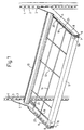
- the angle profiles 8 are interconnected by means of transverse members 9 and 10, respectively. Resting on these in this case is a net-like support plane 11, 12 which forms a support for the desired support surface for the products which are to be placed on the shelf.
- shelf dividers can be mounted on the rods 12 running between the members 9 and 10, and spring-operated product feeders can be arranged in the product compartments formed by the dividers. This has not been shown and does not constitute a part of the present invention.
- the inner ends of the brackets 4 are connected by means of a transverse connecting element 13, suitably in the form of a plate with bent end portions 14, see Fig. 6.
- the plate 13 can then be connected to the two brackets 4 by virtue of the bent end portions 14 being inserted into a slot-shaped opening 15 in a part 16 projecting from each bracket 4. This connection can be made simply at the point of use without using any loose connecting elements or welding.
- the embodiment described of the shelf allows the latter to be transported in a demounted state in a relatively thin pack and to be assembled into an operational shelf at the point of use.
- all that is necessary is for the brackets 4 to be connected by means of the connecting element 13 and the frame-shaped construction 8, 9, 10 to be fastened firmly to the pull-out rails 7 mounted on the brackets 4. This is a great advantage with regard to both transport and storage.
- the shelf can be pulled out from the inner position shown in Fig 1 into the outer position shown in Fig. 2 and locked both in these positions and steplessly in any desired position in between.
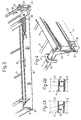
- the shelf comprises friction bodies, which work between the lower edge surface of each fixed rail 6 and, located below the latter, a flange 17 of the associated bracket 4. This is illustrated in greater detail in Fig. 3 and the part enlargements in Figs. 4A and 4B.
- Fig. 3 shows one side of the shelf seen from below with a pull rod 18 running along the angle profile 8 and having a front operating handle 19.
- the pull rod 18 In the unactuated state, the pull rod 18 is held in a retracted position by means of a spring 20, one end of which is fastened to the pull rod and the other end of which is fastened to the rear transverse member 10.
- the rear end of the pull rod 18 is bent so as to form a U-shaped end portion 21 which engages over a transverse bar 22 which runs between the two angle profiles 8 of the shelf.
- Each end of the bar 22 is bent in the form of a crank 23 with a crank pin 24, which pins form the abovementioned friction bodies.
- crank pin 24 projects in through an opening in the associated profile element 8 and into a space formed above the lower flange 17 of the associated bracket 4 for interaction with the flange and the lower edge of the fixed rail 6, see Figs. 4A and 4B.
- the crank pin 24 has a non-circular, suitably square, cross section, and is rotated somewhat in relation to the remainder of the bar 22.
- the crank pin 24 adopts the position shown in Fig. 4A.
- the pin bears against both the flange 17 of the bracket 4 and the lower edge of the fixed rail 6 (not shown in Fig. 4) arranged on the bracket and, by means of this engagement between two stationary surfaces, prevents a relative displacement between the rail and the bracket. This means that the shelf is held locked in this position. In particular, it is made impossible to pull the shelf out.
- a movement of the shelf in the direction of pulling-out tends to increase the engagement force between the comer edges of the crank pin and the flange 17 and, respectively, the rail 6.
- the friction engagement between the crank pin 24 and the flange 17 and, respectively, the rail 6 can be further improved by means of suitable coatings or other finishing of the interacting surfaces.
- the pull rod 18 When the shelf is to be pulled out, the pull rod 18 is actuated via the operating handle 19, and the transverse bar 22 will then move toward the front edge of the shelf. Such a movement results in a certain rotation of the crank pin 24, so that the latter adopts the position shown in Fig. 4B.
- the friction engagement between the crank pin 24 and the flange 17 of the bracket 4 and, respectively, the fixed rail 6 is then freed, and the shelf can be pulled out into the desired position and locked in it by releasing the operating handle 19.
- the spring 20 then rotates the crank pin 24 back into the locking position shown in Fig. 4A.
- the shelf can then be used together with shelves of different depth and still be locked so that the front edges come into line with one another or so that the shelf projects forward a desired distance in front of a shelf lying above in order to bring about what is known as a cascade formation.
- the instantaneous locking of the shelf in the position adopted on release of the operating handle 19 results in the elimination of the risk that personnel will be injured as a consequence of someone losing his grip on a shelf which is inclined forward and downward.
- the shelf would otherwise be able to come out with great force, in particular if it is heavily laden.
- the shelf will be locked instantaneously as soon as the operating handle 19 has been released.
- Fig. 5 illustrates how the location of the pushed-in position of the shelf can be adjusted.
- the angle profiles 8 are made with a number of slot-shaped openings 25, in which a stirrup-shaped stop element 26, for example, can be mounted.
- a stop element 26 mounted in this manner will, when the shelf is pushed in, interact with the front edge surface of the bracket 4 or of the fixed rail 6 mounted thereon and prevent further pushing-in of the shelf.
- the stop position can therefore be adjusted by means of the stirrup-shaped stop elements without regard for any particular locking positions for the locking member, as the invention makes possible stepless locking of the shelf in the desired position.
- Figs. 7-11 illustrate the construction and function of an alternative, preferred embodiment of a locking mechanism for a pull-out shelf according to the invention. Components which have counterparts in figures described previously have been given the same reference numbers as in these figures.
- Figs. 7-9 show only one bracket 4 of the shelf, with the associated braking mechanism. A corresponding mechanism is suitably also mounted on the other bracket of the shelf.
- the bracket 4 is provided with an exchangeable adapter 30 so as to be capable of being mounted on uprights with a different hole spacing.
- the adapter 30 can also be mounted at different heights on the bracket 4 so as to allow fine adjustment of the distance between shelves located one above another.
- bracket 4 Mounted on the bracket 4 is a fixed rail 6.
- the opposite end walls of the shelf are connected to cross-members which are mounted in mountings 32 on each end wall.
- the desired type of shelf plane can then be arranged on the cross-members.
- the brackets are also provided with mounting parts 16 for connecting elements which can be mounted simply at the point of use.
- each locking mechanism comprises a rotatable friction body 33 of rectangular, preferably square, cross section.
- the friction body 33 projects down into a U-shaped rail 34, the legs of which form two opposite engagement surfaces for interaction with the friction body 33.
- the friction body 33 is connected rigidly to a stirrup-shaped link 35 which is coupled to one, bent, end of a pull rod 18 with an operating handle 19.
- the pull rod 18 is brought back into a locking position by means of a compression spring 20 which acts between a fixed washer 36 on the pull rod and a bracket 39.
- the U-shaped rail 34 is fixed in relation to the bracket 4 and is mounted on a lower flange 37 projecting from the bracket.
- An inner part of the flange 37 is provided with adjustment holes 38 for receiving a stop member (not shown) which defines the inner end position of the shelf.
- Fig. 7 shows the shelf end wall 31 in a pushed-in, locked position, that is to say the spring 20 exerts a backwardly directed pressing force on the pull rod 18, so that the friction body 33 is held in the rotational position illustrated in Fig. 10 relative to the side surfaces of the U-shaped rail 34.
- a tensile force acting on the friction body 33 in the direction of the arrow A tends to increase further the friction engagement between the friction body and the opposite engagement surfaces.
- Fig. 9 illustrates the shelf end wall in an outer end position with the pull rod 18 released, the spring 20 again having brought about a rotation of the friction body 33 into the locking position illustrated in Fig. 10.
- Such locking can also be brought about in any other desired position between the inner and outer end positions of the shelf end wall.
- the friction body 33 is oriented vertically and projects down into a rail 34 lying below.
- the friction booy can also be oriented horizontally, for example, and project into a rail arranged on the side surface of the bracket.
- the rail can also be mounted above the pin and interact with the upper end of the latter.
- the compression spring 20 can be replaced by a tension spring acting in the other direction.
- Fig. 1 uses two symmetrically arranged locking mechanisms, it may be sufficient for some applications to make use of a single locking mechanism or an operating member which actuates a separate locking element according to Fig. 7 on each side.
- the locking body shown is of square cross section. However, it can be replaced by another, non-circular cross section which performs the same function.
- a tensile force instead of subjecting the transverse locking bar in Fig 3 to a tensile force, essentially the same function can be achieved by applying a displacing force to it, the rotation of the crank pins then taking place in the opposite direction.
Landscapes
- Drawers Of Furniture (AREA)
- Display Racks (AREA)
- Assembled Shelves (AREA)
- Inductance-Capacitance Distribution Constants And Capacitance-Resistance Oscillators (AREA)
- Warehouses Or Storage Devices (AREA)
- Sink And Installation For Waste Water (AREA)
- Transition And Organic Metals Composition Catalysts For Addition Polymerization (AREA)
- Medicines That Contain Protein Lipid Enzymes And Other Medicines (AREA)
Abstract
Description
Claims (14)
- A pull-out shelf for mounting on rack uprights (1) or the like and comprising two brackets (4) projecting from the uprights or from supports mounted thereon, at least one rail (7) mounted on each bracket so as to be capable of being pulled out, and a shelf plane (8-12) or equivalent, supported by the rails, for articles which are to be placed on the shelf, which shelf comprises at least one releasable locking member (24) which, when an associated operating member (18) is actuated manually, releases the pull-out rails (7), so that these can be pulled out and pushed in, and, in the unactuated state, locks the rails relative to the brackets (4), characterized in that, when the operating member is unactuated, said locking member locks the rails under the action of a spring force, in that said manual actuation of the operating member takes place counter to the action of said spring force, so that releasing said operating member results in instantaneous locking of the rails and thus the shelf in the current position so as to allow stepless locking of the shelf in optional positions between an inner and an outer end position.
- The shelf as claimed in claim 1, characterized in that said locking member follows the movements of the shelf and compnses a friction body (24) projecting in between two engagement surfaces borne by one bracket (4) of the shelf.
- The shelf as claimed in claim 2, characterized in that the friction body (24) has a non-circular cross section, and in that said operating member (18) is adapted so as, when actuated, to bring about a rotation of the friction body from a locking position, in which the friction body is in friction engagement with said engagement surfaces, into a free position, in which it can be displaced relative to these.
- The shelf as claimed in any one of claims 1-3, characterized in that it comprises two locking members, a rotatable friction body (24) being arranged between two engagement surfaces of each bracket (4).
- The shelf as claimed in claim 3 or 4, characterized in that said friction body has a rectangular, preferably square, cross section, and in that, in the locking position, it is rotated in such a manner relative to the two engagement surfaces that the engagement with these increases as a consequence of an outwardly directed tensile force acting on the shelf.
- The shelf as claimed in any one of claims 3-5, characterized in that the operating member intended for rotating said friction body consists of a spring-loaded operating rod arranged on the shelf, which rod, in the unactuated state, holds the friction body in a locking position under the action of the spring force and, when actuated counter to the action of the spring force, rotates the friction body into a free position.
- The shelf as claimed in any one of claims 1-6, characterized in that said engagement surfaces are formed by the legs of a rail with a U-shaped profile arranged on at least one bracket of the shelf.
- The shelf as claimed in claim 7, characterized in that the U-shaped rail is borne by a lower horizontal flange of the bracket.
- The shelf as claimed in any one of claims 1-6, characterized in that said engagement surfaces are formed by a lower horizontal flange of at least one bracket of the shelf and by a lower edge of a fixed guide rail which is borne by the bracket and in which the pull-out rail of the shelf runs.
- The shelf as claimed in any one of claims 4-9, characterized in that said friction bodies (24) consist of the end portions of a bar (22) extending between the brackets (4), in that the bar follows the displacement movements of the shelf, and in that the bar can be rotated by means of said operating member (18).
- The shelf as claimed in any one of claims 1-10, characterized in that it comprises adjustable stop members (26) which are adapted so as to allow adjustment of the location of the inner position of the shelf.
- The shelf as claimed in claim 11, characterized in that said stop members (26) comprise stirrups, pins or equivalent, which can be mounted in any of a number of holes (25) or slots, so that they delimit the pushing-in of the pull-out rail (7) relative to the bracket (4).
- The shelf as claimed in any one of claims 1-12, characterized in that the brackets (4) are interconnected by means of at least one transverse stay (13) which is easy to mount and allows the shelf to be assembled at the point of use.
- The shelf as claimed in any one of claims 1-13, characterized in that those parts (3) of the brackets (4) which interact with slot-shaped holes in the rack uprights (1) are made with adjustment notches (5) so as to allow the shelf to be mounted at different angles relative to the rack uprights (1).
Applications Claiming Priority (3)
| Application Number | Priority Date | Filing Date | Title |
|---|---|---|---|
| SE9903198 | 1999-09-09 | ||
| SE9903198A SE521374C2 (en) | 1999-09-09 | 1999-09-09 | Pull-out shelf |
| PCT/SE2000/001736 WO2001021040A1 (en) | 1999-09-09 | 2000-09-07 | Pull-out shelf |
Publications (2)
| Publication Number | Publication Date |
|---|---|
| EP1221876A1 EP1221876A1 (en) | 2002-07-17 |
| EP1221876B1 true EP1221876B1 (en) | 2004-07-28 |
Family
ID=20416916
Family Applications (1)
| Application Number | Title | Priority Date | Filing Date |
|---|---|---|---|
| EP00963213A Expired - Lifetime EP1221876B1 (en) | 1999-09-09 | 2000-09-07 | Pull-out shelf |
Country Status (7)
| Country | Link |
|---|---|
| US (1) | US6799523B1 (en) |
| EP (1) | EP1221876B1 (en) |
| AT (1) | ATE271811T1 (en) |
| AU (1) | AU7466100A (en) |
| DE (1) | DE60012556T2 (en) |
| SE (1) | SE521374C2 (en) |
| WO (1) | WO2001021040A1 (en) |
Cited By (1)
| Publication number | Priority date | Publication date | Assignee | Title |
|---|---|---|---|---|
| FR2906984A1 (en) * | 2006-10-13 | 2008-04-18 | Driver Sa | Product/article presentation tray for e.g. supermarket, has connection device assuring degree of freedom in direction of tray's width, and operating unit connected to brackets and whose movement varies distance between brackets in direction |
Families Citing this family (67)
| Publication number | Priority date | Publication date | Assignee | Title |
|---|---|---|---|---|
| US7049728B2 (en) * | 2001-12-13 | 2006-05-23 | Linak A/S | Adjustable construction preferably an article of furniture and a squeeze protection and a drive unit thereto |
| AU2003246885A1 (en) * | 2002-02-20 | 2003-09-09 | Martin Hendricken | A retractable display device |
| AU2003266070A1 (en) * | 2003-03-17 | 2004-10-11 | John Michael Harper | Stock shelving system |
| US7497533B2 (en) * | 2003-04-28 | 2009-03-03 | Clairson, Inc. | Shelves, resilient drawer stops, and drawer brackets for supporting shelves and drawers |
| USD547640S1 (en) * | 2003-04-28 | 2007-07-31 | Clairson, Inc. | Drawer bracket |
| ITMO20040061A1 (en) * | 2004-03-23 | 2004-06-23 | Store Van S R L | EXTRACTABLE TOP |
| US7258317B1 (en) | 2004-04-22 | 2007-08-21 | Trion Industries, Inc. | Pull-out display shelf |
| US20070012836A1 (en) * | 2005-07-18 | 2007-01-18 | Dell Products L.P. | Mounting bracket for rack system and method of use |
| US9750354B2 (en) | 2005-09-12 | 2017-09-05 | Rtc Industries, Inc. | Product management display system |
| US8453850B2 (en) | 2005-09-12 | 2013-06-04 | Rtc Industries, Inc. | Product management display system with trackless pusher mechanism |
| US8863963B2 (en) | 2005-09-12 | 2014-10-21 | Rtc Industries, Inc. | Product management display system with trackless pusher mechanism |
| US9486088B2 (en) | 2005-09-12 | 2016-11-08 | Rtc Industries, Inc. | Product management display system |
| US9173504B2 (en) | 2005-09-12 | 2015-11-03 | Rtc Industries, Inc. | Product management display system |
| US11259652B2 (en) | 2005-09-12 | 2022-03-01 | Rtc Industries, Inc. | Product management display system |
| US9060624B2 (en) | 2005-09-12 | 2015-06-23 | Rtc Industries, Inc. | Product management display system with rail mounting clip |
| US8967394B2 (en) | 2005-09-12 | 2015-03-03 | Rtc Industries, Inc. | Product management display system with trackless pusher mechanism |
| US7823734B2 (en) | 2005-09-12 | 2010-11-02 | Rtc Industries, Inc. | Product management display system with trackless pusher mechanism |
| US9138075B2 (en) | 2005-09-12 | 2015-09-22 | Rtc Industries, Inc. | Product management display system |
| US10285510B2 (en) | 2005-09-12 | 2019-05-14 | Rtc Industries, Inc. | Product management display system |
| US9265358B2 (en) | 2005-09-12 | 2016-02-23 | RTC Industries, Incorporated | Product management display system |
| US9265362B2 (en) | 2005-09-12 | 2016-02-23 | RTC Industries, Incorporated | Product management display system |
| US9259102B2 (en) | 2005-09-12 | 2016-02-16 | RTC Industries, Incorporated | Product management display system with trackless pusher mechanism |
| US8312999B2 (en) | 2005-09-12 | 2012-11-20 | Rtc Industries, Inc. | Product management display system with trackless pusher mechanism |
| US11344138B2 (en) | 2005-09-12 | 2022-05-31 | Rtc Industries, Inc. | Product management display system |
| US10952546B2 (en) | 2005-09-12 | 2021-03-23 | Rtc Industries, Inc. | Product management display system with trackless pusher mechanism |
| US9232864B2 (en) | 2005-09-12 | 2016-01-12 | RTC Industries, Incorporated | Product management display system with trackless pusher mechanism |
| US11583109B2 (en) | 2005-09-12 | 2023-02-21 | Rtc Industries, Inc. | Product management display system with trackless pusher mechanism |
| US8739984B2 (en) | 2005-09-12 | 2014-06-03 | Rtc Industries, Inc. | Product management display system with trackless pusher mechanism |
| US8978904B2 (en) | 2005-09-12 | 2015-03-17 | Rtc Industries, Inc. | Product management display system with trackless pusher mechanism |
| US7757890B2 (en) | 2005-10-12 | 2010-07-20 | Rtc Industries, Inc. | Cylindrical container dispenser |
| US20070221103A1 (en) * | 2006-03-24 | 2007-09-27 | Equipment Brokers, Inc. D.B.A Rj Trausch Industries, Inc. | Shelving assembly |
| US20080121563A1 (en) * | 2006-06-06 | 2008-05-29 | Dennis Polvere | Product display systems |
| GB0616979D0 (en) * | 2006-08-29 | 2006-10-04 | Cadbury Schweppes Plc | Product display unit |
| FI7376U1 (en) * | 2006-09-12 | 2007-01-31 | Gws Pikval Oy | Sliding shelf locking mechanism |
| US8056734B2 (en) | 2006-10-23 | 2011-11-15 | Rtc Industries, Inc. | Merchandising system with flippable column and/or item stop |
| DE102007021552A1 (en) * | 2007-05-08 | 2008-11-13 | BSH Bosch und Siemens Hausgeräte GmbH | Extraction unit for a refrigeration unit |
| AT10312U1 (en) | 2007-11-19 | 2009-01-15 | Blum Gmbh Julius | WEARING CONSTRUCTION FOR ATTACHING AT LEAST ONE FURNITURE DRIVE |
| US8276523B2 (en) | 2008-05-28 | 2012-10-02 | Steelcase Inc. | Worksurface assembly |
| US7940460B2 (en) * | 2009-02-13 | 2011-05-10 | Ykk Corporation Of America | Light shelf assembly and methods of installing the same |
| US9451836B2 (en) * | 2012-08-03 | 2016-09-27 | Fasteners For Retail, Inc. | Sliding and pivoting retainer |
| US9578976B2 (en) * | 2012-08-03 | 2017-02-28 | Fasteners For Retail, Inc. | Adjustable mounting structure for a shelving system |
| US8800785B2 (en) * | 2012-09-27 | 2014-08-12 | Midland Metal Products | Merchandising display device |
| USD801734S1 (en) | 2014-12-01 | 2017-11-07 | Retail Space Solutions Llc | Shelf management parts |
| US10154739B2 (en) | 2013-12-02 | 2018-12-18 | Retail Space Solutions Llc | Universal merchandiser and methods relating to same |
| US9404290B2 (en) * | 2013-12-17 | 2016-08-02 | Se-Kure Controls, Inc. | Securable article display |
| WO2016008040A1 (en) * | 2014-07-14 | 2016-01-21 | Otten & Otten Construction Limited | Brace for step ladder |
| USD790267S1 (en) | 2015-02-18 | 2017-06-27 | Big Skies Limited | Pull-out shelf unit |
| US9955802B2 (en) | 2015-04-08 | 2018-05-01 | Fasteners For Retail, Inc. | Divider with selectively securable track assembly |
| WO2017015466A1 (en) * | 2015-07-23 | 2017-01-26 | Dci Marketing, Inc. | Merchandiser and methods relating to same |
| US10314412B2 (en) * | 2015-09-10 | 2019-06-11 | Retail Space Solutions Llc | Retractable hinged shelf display |
| EP3402371B1 (en) | 2016-01-13 | 2020-03-04 | RTC Industries, Inc. | Merchandise display system with an anti-splay device |
| US10334967B2 (en) | 2016-07-25 | 2019-07-02 | Retail Space Solutions Llc | Merchandiser and methods relating to same |
| US10959540B2 (en) | 2016-12-05 | 2021-03-30 | Retail Space Solutions Llc | Shelf management system, components thereof, and related methods |
| CA3058797A1 (en) | 2017-04-27 | 2018-11-01 | Retail Space Solutions Llc | Shelf-mounted tray and methods relating to same |
| WO2018232271A1 (en) | 2017-06-16 | 2018-12-20 | Rtc Industries, Inc. | Product management display system with trackless pusher mechanism |
| CN112867420B (en) * | 2018-07-17 | 2022-01-04 | 赛峰客舱荷兰公司 | Container extraction assembly |
| US10589770B1 (en) * | 2018-09-06 | 2020-03-17 | Christie Lites Enterprises Canada Inc. | Fixture securing system and method of use |
| US20200107634A1 (en) * | 2018-10-06 | 2020-04-09 | Royston Llc | Roll-out shelving system |
| CN110236298B (en) * | 2019-06-19 | 2024-03-08 | 宁波圣达智能科技有限公司 | Compact shelf and operation pipe handle thereof |
| EP4297613A4 (en) * | 2021-02-24 | 2025-01-01 | Roll Out Racks Products | MODULAR CANTILEVER ARMS FOR MODULAR CANTILEVER SHELVING SYSTEMS |
| CN223071362U (en) * | 2022-03-22 | 2025-07-08 | 米沃奇电动工具公司 | Support structure |
| US12207743B2 (en) * | 2022-09-16 | 2025-01-28 | Henschel-Steinau, Inc. | Pullout support assembly for merchandise display and dispensing modules |
| US12207742B2 (en) * | 2022-10-24 | 2025-01-28 | Fasteners For Retail, Inc. | Pullout shelf |
| US20250134280A1 (en) * | 2023-11-01 | 2025-05-01 | Sennco Solutions Inc. | Anti-sweep bar |
| DE102024109882A1 (en) * | 2024-04-09 | 2025-10-09 | Agoform Gmbh | Pusher device |
| US12426709B1 (en) | 2024-09-10 | 2025-09-30 | Jay A. Berkowitz | Apparatus and method for releasably locked furniture |
| US12262812B1 (en) * | 2024-09-10 | 2025-04-01 | Jay A. Berkowitz | Apparatus and method for a releasably locked desktop in a modular cubicle |
Family Cites Families (13)
| Publication number | Priority date | Publication date | Assignee | Title |
|---|---|---|---|---|
| US2564473A (en) * | 1947-03-15 | 1951-08-14 | Gen Electric | Sliding shelf |
| US2728626A (en) * | 1954-08-30 | 1955-12-27 | Grant Pulley & Hardware Corp | Multiple position locking slide |
| US3248079A (en) * | 1963-12-30 | 1966-04-26 | Clark Equipment Co | Angularly adjustable shelf bracket |
| US3746418A (en) * | 1971-03-22 | 1973-07-17 | Standard Precision Inc | Adjustable stops for drawer slides |
| US4378925A (en) * | 1981-03-10 | 1983-04-05 | Lingo Manufacturing Company | T-Bracket shelf assembly |
| US4620489A (en) * | 1982-09-07 | 1986-11-04 | The Kent Corporation | Extendible merchandise shelving display |
| US4669692A (en) * | 1984-03-26 | 1987-06-02 | Mastrodicasa Arthur R | Adjustable bracket assembly for supporting a shelf |
| DE3425517A1 (en) * | 1984-07-11 | 1986-01-16 | Paul Hettich GmbH & Co, 4983 Kirchlengern | Guide for drawers or the like |
| US4610487A (en) * | 1985-09-16 | 1986-09-09 | Standard Precision, Inc. | Drawer slide with lock |
| US4751884A (en) * | 1985-10-09 | 1988-06-21 | Hauseman, Inc. | Height adjustable work top |
| US4735470A (en) * | 1986-03-28 | 1988-04-05 | General Electric Company | Refrigerator including a secondary food storage arrangement |
| US4679950A (en) * | 1986-09-22 | 1987-07-14 | Standard Precision, Inc. | Drawer slide with infinite adjustment locking mechanism |
| DE3716923A1 (en) * | 1987-05-20 | 1988-12-08 | Lautenschlaeger Kg Karl | EXTENSION GUIDE |
-
1999
- 1999-09-09 SE SE9903198A patent/SE521374C2/en not_active IP Right Cessation
-
2000
- 2000-09-07 EP EP00963213A patent/EP1221876B1/en not_active Expired - Lifetime
- 2000-09-07 US US10/070,639 patent/US6799523B1/en not_active Expired - Fee Related
- 2000-09-07 DE DE60012556T patent/DE60012556T2/en not_active Expired - Fee Related
- 2000-09-07 AU AU74661/00A patent/AU7466100A/en not_active Abandoned
- 2000-09-07 WO PCT/SE2000/001736 patent/WO2001021040A1/en not_active Ceased
- 2000-09-07 AT AT00963213T patent/ATE271811T1/en not_active IP Right Cessation
Cited By (1)
| Publication number | Priority date | Publication date | Assignee | Title |
|---|---|---|---|---|
| FR2906984A1 (en) * | 2006-10-13 | 2008-04-18 | Driver Sa | Product/article presentation tray for e.g. supermarket, has connection device assuring degree of freedom in direction of tray's width, and operating unit connected to brackets and whose movement varies distance between brackets in direction |
Also Published As
| Publication number | Publication date |
|---|---|
| EP1221876A1 (en) | 2002-07-17 |
| WO2001021040A1 (en) | 2001-03-29 |
| DE60012556T2 (en) | 2005-09-29 |
| WO2001021040A8 (en) | 2001-05-31 |
| SE9903198D0 (en) | 1999-09-09 |
| US6799523B1 (en) | 2004-10-05 |
| DE60012556D1 (en) | 2004-09-02 |
| AU7466100A (en) | 2001-04-24 |
| SE9903198L (en) | 2001-03-10 |
| SE521374C2 (en) | 2003-10-28 |
| ATE271811T1 (en) | 2004-08-15 |
Similar Documents
| Publication | Publication Date | Title |
|---|---|---|
| US6799523B1 (en) | Pull-out shelf | |
| US3995927A (en) | Front release drawer slide | |
| JP2791753B2 (en) | Differential drawer for drawers or the like | |
| EP2268985B1 (en) | Refrigeration apparatus and associated latching means arrangement for subsequent attachment | |
| US5738019A (en) | Adjustable shelf assembly for merchandising display stand | |
| US4934645A (en) | Shelving assembly | |
| US7258317B1 (en) | Pull-out display shelf | |
| EP3006833B1 (en) | Device for guiding the movement of a drawer element, drawer element and furniture | |
| GB2283407A (en) | Adjustable shelf | |
| EP3539524A1 (en) | Clamped bar for nursing- or organization trolley | |
| US5044508A (en) | Goods presentation system having height-adjustable bracket elements in a wall arrangement or pillar arrangement | |
| DE202004021747U1 (en) | Shelf for a refrigeration device | |
| EP0669439A1 (en) | Cabinet locking device | |
| US12617071B2 (en) | Storage unit for tools | |
| DE19907050A1 (en) | Cooling unit | |
| US5902029A (en) | Pullout assembly for a tall cupboard | |
| US3537596A (en) | Suspension arm supporting means | |
| DE19944232C2 (en) | Arrangement for installation in a closet | |
| DE202013006958U1 (en) | Device for presenting goods | |
| GB2150817A (en) | Display apparatus | |
| US3807320A (en) | Rack assembly | |
| US11395547B2 (en) | Rack system | |
| JP2748098B2 (en) | Equipment for fixing drawer-type shelves on shelves | |
| EP1145675A1 (en) | Fastening system for bathroom items | |
| EP0153156A2 (en) | Furniture element and furniture incorporating it |
Legal Events
| Date | Code | Title | Description |
|---|---|---|---|
| PUAI | Public reference made under article 153(3) epc to a published international application that has entered the european phase |
Free format text: ORIGINAL CODE: 0009012 |
|
| 17P | Request for examination filed |
Effective date: 20020311 |
|
| AK | Designated contracting states |
Kind code of ref document: A1 Designated state(s): AT BE CH CY DE DK ES FI FR GB GR IE IT LI LU MC NL PT SE |
|
| AX | Request for extension of the european patent |
Free format text: AL;LT PAYMENT 20020309;LV PAYMENT 20020309;MK;RO PAYMENT 20020309;SI PAYMENT 20020309 |
|
| GRAP | Despatch of communication of intention to grant a patent |
Free format text: ORIGINAL CODE: EPIDOSNIGR1 |
|
| GRAS | Grant fee paid |
Free format text: ORIGINAL CODE: EPIDOSNIGR3 |
|
| GRAA | (expected) grant |
Free format text: ORIGINAL CODE: 0009210 |
|
| AK | Designated contracting states |
Kind code of ref document: B1 Designated state(s): AT BE CH CY DE DK ES FI FR GB GR IE IT LI LU MC NL PT SE |
|
| AX | Request for extension of the european patent |
Extension state: LT LV RO SI |
|
| PG25 | Lapsed in a contracting state [announced via postgrant information from national office to epo] |
Ref country code: IT Free format text: LAPSE BECAUSE OF FAILURE TO SUBMIT A TRANSLATION OF THE DESCRIPTION OR TO PAY THE FEE WITHIN THE PRESCRIBED TIME-LIMIT;WARNING: LAPSES OF ITALIAN PATENTS WITH EFFECTIVE DATE BEFORE 2007 MAY HAVE OCCURRED AT ANY TIME BEFORE 2007. THE CORRECT EFFECTIVE DATE MAY BE DIFFERENT FROM THE ONE RECORDED. Effective date: 20040728 Ref country code: CH Free format text: LAPSE BECAUSE OF FAILURE TO SUBMIT A TRANSLATION OF THE DESCRIPTION OR TO PAY THE FEE WITHIN THE PRESCRIBED TIME-LIMIT Effective date: 20040728 Ref country code: BE Free format text: LAPSE BECAUSE OF FAILURE TO SUBMIT A TRANSLATION OF THE DESCRIPTION OR TO PAY THE FEE WITHIN THE PRESCRIBED TIME-LIMIT Effective date: 20040728 Ref country code: AT Free format text: LAPSE BECAUSE OF FAILURE TO SUBMIT A TRANSLATION OF THE DESCRIPTION OR TO PAY THE FEE WITHIN THE PRESCRIBED TIME-LIMIT Effective date: 20040728 Ref country code: NL Free format text: LAPSE BECAUSE OF FAILURE TO SUBMIT A TRANSLATION OF THE DESCRIPTION OR TO PAY THE FEE WITHIN THE PRESCRIBED TIME-LIMIT Effective date: 20040728 Ref country code: FI Free format text: LAPSE BECAUSE OF FAILURE TO SUBMIT A TRANSLATION OF THE DESCRIPTION OR TO PAY THE FEE WITHIN THE PRESCRIBED TIME-LIMIT Effective date: 20040728 Ref country code: LI Free format text: LAPSE BECAUSE OF FAILURE TO SUBMIT A TRANSLATION OF THE DESCRIPTION OR TO PAY THE FEE WITHIN THE PRESCRIBED TIME-LIMIT Effective date: 20040728 Ref country code: CY Free format text: LAPSE BECAUSE OF FAILURE TO SUBMIT A TRANSLATION OF THE DESCRIPTION OR TO PAY THE FEE WITHIN THE PRESCRIBED TIME-LIMIT Effective date: 20040728 |
|
| REG | Reference to a national code |
Ref country code: GB Ref legal event code: FG4D |
|
| REG | Reference to a national code |
Ref country code: CH Ref legal event code: EP |
|
| REG | Reference to a national code |
Ref country code: IE Ref legal event code: FG4D |
|
| REF | Corresponds to: |
Ref document number: 60012556 Country of ref document: DE Date of ref document: 20040902 Kind code of ref document: P |
|
| PG25 | Lapsed in a contracting state [announced via postgrant information from national office to epo] |
Ref country code: IE Free format text: LAPSE BECAUSE OF NON-PAYMENT OF DUE FEES Effective date: 20040907 |
|
| PG25 | Lapsed in a contracting state [announced via postgrant information from national office to epo] |
Ref country code: MC Free format text: LAPSE BECAUSE OF NON-PAYMENT OF DUE FEES Effective date: 20040930 Ref country code: LU Free format text: LAPSE BECAUSE OF NON-PAYMENT OF DUE FEES Effective date: 20040930 |
|
| PG25 | Lapsed in a contracting state [announced via postgrant information from national office to epo] |
Ref country code: DK Free format text: LAPSE BECAUSE OF FAILURE TO SUBMIT A TRANSLATION OF THE DESCRIPTION OR TO PAY THE FEE WITHIN THE PRESCRIBED TIME-LIMIT Effective date: 20041028 Ref country code: SE Free format text: LAPSE BECAUSE OF FAILURE TO SUBMIT A TRANSLATION OF THE DESCRIPTION OR TO PAY THE FEE WITHIN THE PRESCRIBED TIME-LIMIT Effective date: 20041028 Ref country code: GR Free format text: LAPSE BECAUSE OF FAILURE TO SUBMIT A TRANSLATION OF THE DESCRIPTION OR TO PAY THE FEE WITHIN THE PRESCRIBED TIME-LIMIT Effective date: 20041028 |
|
| PG25 | Lapsed in a contracting state [announced via postgrant information from national office to epo] |
Ref country code: ES Free format text: LAPSE BECAUSE OF FAILURE TO SUBMIT A TRANSLATION OF THE DESCRIPTION OR TO PAY THE FEE WITHIN THE PRESCRIBED TIME-LIMIT Effective date: 20041108 |
|
| NLV1 | Nl: lapsed or annulled due to failure to fulfill the requirements of art. 29p and 29m of the patents act | ||
| LTIE | Lt: invalidation of european patent or patent extension |
Effective date: 20040728 |
|
| REG | Reference to a national code |
Ref country code: CH Ref legal event code: PL |
|
| ET | Fr: translation filed | ||
| REG | Reference to a national code |
Ref country code: IE Ref legal event code: MM4A |
|
| PLBE | No opposition filed within time limit |
Free format text: ORIGINAL CODE: 0009261 |
|
| STAA | Information on the status of an ep patent application or granted ep patent |
Free format text: STATUS: NO OPPOSITION FILED WITHIN TIME LIMIT |
|
| 26N | No opposition filed |
Effective date: 20050429 |
|
| PGFP | Annual fee paid to national office [announced via postgrant information from national office to epo] |
Ref country code: GB Payment date: 20050830 Year of fee payment: 6 |
|
| PGFP | Annual fee paid to national office [announced via postgrant information from national office to epo] |
Ref country code: FR Payment date: 20050831 Year of fee payment: 6 |
|
| PGFP | Annual fee paid to national office [announced via postgrant information from national office to epo] |
Ref country code: DE Payment date: 20050927 Year of fee payment: 6 |
|
| PG25 | Lapsed in a contracting state [announced via postgrant information from national office to epo] |
Ref country code: DE Free format text: LAPSE BECAUSE OF NON-PAYMENT OF DUE FEES Effective date: 20070403 |
|
| GBPC | Gb: european patent ceased through non-payment of renewal fee |
Effective date: 20060907 |
|
| REG | Reference to a national code |
Ref country code: FR Ref legal event code: ST Effective date: 20070531 |
|
| PG25 | Lapsed in a contracting state [announced via postgrant information from national office to epo] |
Ref country code: GB Free format text: LAPSE BECAUSE OF NON-PAYMENT OF DUE FEES Effective date: 20060907 |
|
| PG25 | Lapsed in a contracting state [announced via postgrant information from national office to epo] |
Ref country code: PT Free format text: LAPSE BECAUSE OF NON-PAYMENT OF DUE FEES Effective date: 20041228 |
|
| PG25 | Lapsed in a contracting state [announced via postgrant information from national office to epo] |
Ref country code: FR Free format text: LAPSE BECAUSE OF NON-PAYMENT OF DUE FEES Effective date: 20061002 |