EP1221763A2 - Methods of optimizing performance parameters of a switched reluctance machine - Google Patents
Methods of optimizing performance parameters of a switched reluctance machine Download PDFInfo
- Publication number
- EP1221763A2 EP1221763A2 EP01204858A EP01204858A EP1221763A2 EP 1221763 A2 EP1221763 A2 EP 1221763A2 EP 01204858 A EP01204858 A EP 01204858A EP 01204858 A EP01204858 A EP 01204858A EP 1221763 A2 EP1221763 A2 EP 1221763A2
- Authority
- EP
- European Patent Office
- Prior art keywords
- parameters
- motor
- torque
- falling
- drive efficiency
- Prior art date
- Legal status (The legal status is an assumption and is not a legal conclusion. Google has not performed a legal analysis and makes no representation as to the accuracy of the status listed.)
- Withdrawn
Links
Images




Classifications
-
- H—ELECTRICITY
- H02—GENERATION; CONVERSION OR DISTRIBUTION OF ELECTRIC POWER
- H02P—CONTROL OR REGULATION OF ELECTRIC MOTORS, ELECTRIC GENERATORS OR DYNAMO-ELECTRIC CONVERTERS; CONTROLLING TRANSFORMERS, REACTORS OR CHOKE COILS
- H02P25/00—Arrangements or methods for the control of AC motors characterised by the kind of AC motor or by structural details
- H02P25/02—Arrangements or methods for the control of AC motors characterised by the kind of AC motor or by structural details characterised by the kind of motor
- H02P25/08—Reluctance motors
- H02P25/098—Arrangements for reducing torque ripple
Definitions
- the present invention pertains to the optimization of switched reluctance (SR) machines by determining various performance parameters and analyzing those parameters to optimize the operation of the machine.
- SR switched reluctance
- a switched reluctance (SR) motor comprises a ring shaped stator that has a plurality of pole positions defined by wire coils and disposed in a circular arrangement, a rotor disposed rotatably in an inner space defined by the stator having pole protrusions that face the pole portions of the stator.
- the rotor is an iron core formed by stacking iron plates.
- Switched reluctance motors generate torque by utilizing a magnetic attractive force that acts between the rotor and the stator when the coils are magnetized.
- Conventional SR motors normally suffer vibration problems.
- the magnetic attractive force acting between the stator and the rotor is generally circumferential in direction and quickly increases as the rotor rotates during a cycle of the electric current distribution (to selected coils) and then abruptly terminates at the time of switching the current distribution (to other coils). This on - off cycle of magnetic attractive force causes the rotor and the stator to vibrate in generally circumferential directions. See U.S. Patent 5,747,912.
- a conventional switched reluctance motor is shown in Figure 32 of U.S. Patent 5,880,549 which comprises a four pole rotor where in each of the poles protrudes cross-wisely around the rotating shaft and a six-pole stator arranged around the rotor, each of the protruding poles of the stator having a concentrating winding.
- the current passes through the winding is unidirectional and includes a distorted wave current and direct current component.
- Described is a method of optimizing performance parameters of a switched reluctance motor comprising ascertaining the parameters of at least three objectives of the motor, each as a function of at least one parameter.
- Described is a method of optimizing performance parameters of a switched reluctance motor comprising ascertaining the parameters of at least three objectives of the motor selected from the group consisting of firing angles, power on the shaft of the motor, drive efficiency, torque ripple coefficient, output torque, torque per rms (root-mean-square) current per cycle, torque per mean ampere, energy consumption, phase target current level, hysteresis band size, duty cycle, DC voltage and zero-volt control loop, and the like;
- This invention presents a new technique for the search of optimum control parameters of a switched reluctance drive.
- the firing angles (turn-on and turn-off) are chosen that achieve high drive efficiency with lowest torque ripple in the entire Torque (Power)-Speed operation of a Switched Reluctance Motor drive.
- the technique is based on mapping performance quantities as functions of turn-on and turn-off angles at each selected motor speed.
- the bounds of the control angles are functions of geometrical parameters of the SR motor (SRM). For a given mechanical output required from a given SRM drive (torque, speed), there are several possible sets of control parameters. But for each of these sets of parameters, the efficiencies, the shaft torque waveforms (torque ripple) and other performance quantities will vary.
- the new Technique is based on the following principles:
- This invention provides a new technique for the search of optimum firing angles (turn-on and turn-off) achieving high drive efficiency with lowest torque ripple in the entire Torque (Power)-Speed operation plane of a Switched Reluctance Motor drive.
- the technique is based on mapping performance qualities as functions of turn-on and turn-off angles at each selected motor speed (See Figs.).
- the bounds of the control angles are functions of geometrical parameters of the SR motor. For a given mechanical output required from a given SRM drive (torque, speed), there are several possible sets of control parameters. But for each of these sets of parameters, the efficiencies, the shaft torque waveforms (torque ripple) and other performance qualities will vary.
- the present invention shows how to best select among many firing angles that provide the desired output power (62 kW in this example). Assume, for instance, that efficiency and torque ripple are important for that particular application. These two parameters, efficiency and torque ripple, are calculated for each operating point represented on the 3-D contour shown on Fig. 1A. The values of efficiency and torque ripple (the latter being represented by a so-called Torque Ripple Coefficient defined latter) for every point on the 3-D contour and then projected onto a 2-D plan as map of isovalues. Fig. 1B shows such projections for the torque ripple coefficient. The 62-kW points are also shown as a dotted line. Points inside the 62-kW line correspond in this case to power levels larger than 62 kW, and were projected downward to produce this plot. Likewise points outside the 62-kW line correspond to power levels smaller than 62 Kw, and were projected upward. Fig. 1C is similar, with drive efficiency data.
- a subsequent step in choosing operating parameters consists of superposing the various desirable 2-D maps.
- Fig. 1D in this example superimposes the maps plotted as Fig. 1B and 1C. It also includes the 62-kW power level as a broken line.
- the points between points R and Q on the 62-kW line by contrast, generate the same power but with an efficiency of more than 96% and a torque ripple coefficient between 75% and 100%.
- the chosen operating point should be chosen between points R and Q.
- R and Q may be performed by fine tuning the plot to target, for instance, the highest possible efficiency on that segment.
- an additional map of isovalues may be superimposed on top of the present two, for instance to minimize the phase target current level.
- the Mechanical Output Map on Fig. 1A shows that a multitude of combinations of turn-on and turn-off angles can engender 62 kW out of the considered motor.
- Fig. 1D shows also that the considered SRM drive can deliver more than 62 kW at 16200 rpm with a torque ripple content less than 75%. Such operating point is illustrated by point S on Fig. 1D.
- the method can be used to optimize a drive in any number of ways. For instance, if a specification calls for a torque ripple coefficient of at most 75%, the 3-D map shown in Fig. 1A would now plot torque ripple coefficient on the z-axis (instead of power on the shaft as shown on the figure). Plots of, for instance, isovalues of power and isovalues of efficiency would then be drawn in order to, say, maximize output power and efficiency at the desired level of at the most 75% torque ripple coefficient.
- control parameters such as turn-on and turn-off angles
- Other control parameters such as phase current target level or zero-voltage control loop (defined later) were kept constant during the calculations leading to the plotting of Fig. 1A, B and C. If it is desirable to include another parameter, say, phase current target level, along with turn-on and turn-off angles, the present method can be used as follows.
- a first option consists of building a 4-D map of power versus turn-on angle, turn-off angle and phase current target level. Such a 4-D map could not be visualized but could be used by known mathematical algorithms to search for optimum. This method, sometimes, however, yields a local optimum.
- a second option is to draw three maps like the Fig. 1D map, plotting isovalues in terms of (turn-on; turn-off); (turn-on; phase current), (turn-off; phase current), and using the three plots to visually choose the optimum.
- This technique was successfully used off-line for determining optimum firing angles in two SRM drive prototypes intended for Electric Vehicle Propulsion.
- firing angles is meant: the turn-on angle and turn-off angle (see Figure 2A).
- Turn-on angle is the value of rotor position at which a machine phase is energized. At this position, a positive value of voltage is applied across a machine phase winding (Fig. A).
- power on the shaft is meant: the mechanical power on the machine shaft. It means the product "Average torque x speed”.
- the average torque is the average value of the motor instantaneous torque over the machine angular period of operation (Fig. 2B). For a switched reluctance machine, the angular period equals to the rotor pole pitch (360 degrees divided by the number of rotor poles).
- drive efficiency is meant: the ratio Power on the shaft / Electrical power feeding the drive .
- the electrical power feeding the drive equals the product of DC voltage applied to the drive time the average value of the electrical current absorbed by the drive.
- the drive efficiency is the reverse of the above.
- output torque is meant: the average torque on the motor shaft.
- torque per mean ampere is meant: the ratio Average torque / Phase mean current.
- a phase mean current is the average value of the phase instantaneous current over an angular period of operation.
- energy consumption is meant: electrical power ( voltage x current) consumed by the drive over the operation time (for an SR machine working as a motor).
- phase target current level is meant: the value of maximum current that can be reached into a motor phase.
- the machine is in a Single Pulse mode of operation (Fig. 2A-2B). If the current tends to go over the target current level (this can happen only when the rotor position is in between the turn-on angle and the turn-off angle), the machine enters a Current Control mode of operation (Fig. 1C).
- hysteresis band size is meant: the interval in which the electrical current flowing into a motor phase is maintained during a current control mode of operation (Fig. 2C).
- duty cycle is meant: the coefficient of reduction of a DC voltage due to a voltage chopping.
- zero volt control loop is meant: the angular interval in which the applied voltage in a motor phase equals to zero volt (Fig. 2A).
Landscapes
- Engineering & Computer Science (AREA)
- Power Engineering (AREA)
- Control Of Electric Motors In General (AREA)
Abstract
Description
- The present invention pertains to the optimization of switched reluctance (SR) machines by determining various performance parameters and analyzing those parameters to optimize the operation of the machine.
- The present invention relates to generators as well as to motors. To simplify the description, what follows pertains to a motor with the understanding invention also relates to generators. A switched reluctance (SR) motor comprises a ring shaped stator that has a plurality of pole positions defined by wire coils and disposed in a circular arrangement, a rotor disposed rotatably in an inner space defined by the stator having pole protrusions that face the pole portions of the stator. Normally, the rotor is an iron core formed by stacking iron plates. When supplied with electricity, the wire coils become magnetized together with the pole portions to attract the pole protrusions of the rotor. The rotor is continuously rotated by selectively distributing electric current to the coils.
- Switched reluctance motors generate torque by utilizing a magnetic attractive force that acts between the rotor and the stator when the coils are magnetized. Conventional SR motors normally suffer vibration problems. The magnetic attractive force acting between the stator and the rotor is generally circumferential in direction and quickly increases as the rotor rotates during a cycle of the electric current distribution (to selected coils) and then abruptly terminates at the time of switching the current distribution (to other coils). This on - off cycle of magnetic attractive force causes the rotor and the stator to vibrate in generally circumferential directions. See U.S. Patent 5,747,912.
- A conventional switched reluctance motor is shown in Figure 32 of U.S. Patent 5,880,549 which comprises a four pole rotor where in each of the poles protrudes
cross-wisely around the rotating shaft and a six-pole stator arranged around the rotor, each of the protruding poles of the stator having a concentrating winding. The current passes through the winding is unidirectional and includes a distorted wave current and direct current component. - Other switched reluctance motors are described in U.S. Patents 6,028,385, 6,014,012, 6,002,233, 5,945,761 and 5,900,712; all of which are here by incorporated by reference.
- In the field of electric machines of the Switched Reluctance type, it is well known that the machine performance (efficiency, output torque, torque ripple, etc.) is a function of when the current is turned-on and turned-off. (So-called turn-on and turn-off angles). It is also well known that the best angles will be different depending on speed, voltage, etc. Therefore others have looked for ways to take advantage of this to optimally design Switched Reluctance Motors (SRM). So far, however attempts have been confined to the following:
- an analytical or numerical optimization of one performance quality (efficiency, output torque, torque ripple, torque per ampere, energy, etc.) at a time. Because of the complexity of the physics and mathematics involved, however, people have only optimized with one parameter (say, efficiency) with at the most minor fine-tuning around the chosen point to improve together parameters (reduce torque ripple for instance). For example, reference (1) maximizes the Torque per Ampere only while reference (2) minimizes the energy consumption, by means of the root-mean-square (rms) phase current.
-
- [1] B. Fahimi et al. "Self-Turning of Switched Reluctance Motors for Optimized Torque per Ampere at all Operating Points". Proceedings of IEEE Applied Power Electronics Conference, APEC '98, pp. 778-783, Feb. 1998.
- [2] Ph.C.Kjaer et al. "A New Energy control Strategy for Switched Reluctance Motors". IEEE Transactions on Industry Applications, Vol. 31, No. 5, pp. 1088-1095, Sep./Oct. 1995.
-
- limitations, one has essentially optimized for single performance quantity. This method requires that a prototype has already been built. In published literature, people usually do not specify explicitly that an empirical approach was used. Specific statements giving numbers without theoretical justification often mean that this kind of approach was used [3].
-
- [3] K.M. McLaughlin, M.W. Gluch. "Method and Apparatus for Controlling an
Electric Assist Steering System using Two-dimensional Interpolation for
Current Commands". US Patent # 5,475,289. December 12, 1995.
It is an object of the present invention to provide a method of optimizing the performance parameters for a switched reluctance motor by obtaining the parameters of at least three objectives of the motor, plotting the parameters on a two or three dimensional chart and then mapping all of the parameters onto one chart. -
- Described is a method of optimizing performance parameters of a switched reluctance motor comprising ascertaining the parameters of at least three objectives of the motor, each as a function of at least one parameter.
- Described is a method of optimizing performance parameters of a switched reluctance motor comprising ascertaining the parameters of at least three objectives of the motor selected from the group consisting of firing angles, power on the shaft of the motor, drive efficiency, torque ripple coefficient, output torque, torque per rms (root-mean-square) current per cycle, torque per mean ampere, energy consumption, phase target current level, hysteresis band size, duty cycle, DC voltage and zero-volt control loop, and the like;
- plotting the parameters on an x-y (2 Dimension) or x-y-z chart (3 Dimension); and
- mapping all of the desired parameters on to one chart and thereby ascertaining the optimum performance of the at least three parameters.
-
- Also described is a method of operating a switched reluctance motor by ascertaining the optimum performance parameters as described above and operating the switched reluctance motor utilizing those parameters.
-
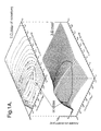
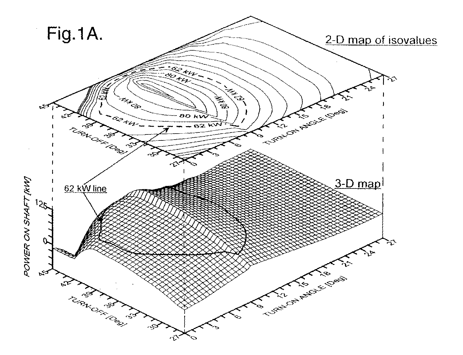
- Figure 1A plots the mechanical output power map of a given switched reluctance (SR) machine at a constant motor speed of 16,200 rpm (revolutions per minute) as a function of firing angles (turn-on and turn-off).
- Figure 1B is a plot of the switched reluctance machine torque ripple coefficient map at a constant motor speed of 16,200 rpm as a function of firing angles (turned on and turned off) (vehicle axle speed equals 1350 rpm).
- Figure 1C is a plot of a switched reluctance machine efficiency map at a constant motor speed of 16,200 rpm as a function of firing angles turn on and turn off (vehicle axle speed equals 1350 rpm).
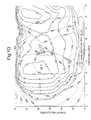
- Figure 1D is a two dimensional plot of the parameters depicted in Figures 1A, 1B and 1C; the plot shows the optimum firing angles for the vehicle axle operation with maximum drive efficiency and minimum torque ripple (at 62 kW, 1350 rpm).
- Figure 2A is a time dimensional plot of SR motor in a single pulse mode of operation.
- Figure 2B is a time dimensional plot of SR motor in a Single Pulse mode of operation.
- Figure 2C is a time dimensional plot of SR motor in a Current Control mode of operation.
-
- This invention presents a new technique for the search of optimum control parameters of a switched reluctance drive. In the specific example described herein, the firing angles (turn-on and turn-off) are chosen that achieve high drive efficiency with lowest torque ripple in the entire Torque (Power)-Speed operation of a Switched Reluctance Motor drive. The technique is based on mapping performance quantities as functions of turn-on and turn-off angles at each selected motor speed. The bounds of the control angles are functions of geometrical parameters of the SR motor (SRM). For a given mechanical output required from a given SRM drive (torque, speed), there are several possible sets of control parameters. But for each of these sets of parameters, the efficiencies, the shaft torque waveforms (torque ripple) and other performance quantities will vary.
- The method is explained with efficiency and torque ripple as key objectives. It may be used with other goals including, but not limited to: output torque, torque per rms ampere, torque per mean ampere, energy consumption, etc.
- The method is also applicable to a switched reluctance machine operating as a generator.
- The method can be used with three or more key objectives at a time.
- The method permits finding the optimum firing angles (turn-on and turn-off) as control parameters. It could also be used for finding other control parameters including, but not limited to phase target current level, hysteresis band size, duty cycle, DC voltage level, zero-volt control loop, and the like.
- The new Technique is based on the following principles:
- (a) Mapping SR drive performance quantities as functions of turn-on and turn-off angles at any selected motor speed.
- (b) Superposition of all generated maps in order to create a global final map for the selected motor.
-
- The intersections of curves relative to all considered performance quantities give the optimums of the desired quantities and the corresponding optimum control parameters (firing angles, phase target current level. hysteresis band size, duty cycle, DC voltage level, zero-volt control loop, etc.)
- This invention provides a new technique for the search of optimum firing angles (turn-on and turn-off) achieving high drive efficiency with lowest torque ripple in the entire Torque (Power)-Speed operation plane of a Switched Reluctance Motor drive. The technique is based on mapping performance qualities as functions of turn-on and turn-off angles at each selected motor speed (See Figs.). The bounds of the control angles are functions of geometrical parameters of the SR motor. For a given mechanical output required from a given SRM drive (torque, speed), there are several possible sets of control parameters. But for each of these sets of parameters, the efficiencies, the shaft torque waveforms (torque ripple) and other performance qualities will vary.
- Let us consider a given SRM drive and then compute its performance maps (Figs.) at a selected motor speed equal to 16200 rpm, for example.
- The present invention shows how to best select among many firing angles that provide the desired output power (62 kW in this example). Assume, for instance, that efficiency and torque ripple are important for that particular application. These two parameters, efficiency and torque ripple, are calculated for each operating point represented on the 3-D contour shown on Fig. 1A. The values of efficiency and torque ripple (the latter being represented by a so-called Torque Ripple Coefficient defined latter) for every point on the 3-D contour and then projected onto a 2-D plan as map of isovalues. Fig. 1B shows such projections for the torque ripple coefficient. The 62-kW points are also shown as a dotted line. Points inside the 62-kW line correspond in this case to power levels larger than 62 kW, and were projected downward to produce this plot. Likewise points outside the 62-kW line correspond to power levels smaller than 62 Kw, and were projected upward. Fig. 1C is similar, with drive efficiency data.
- A subsequent step in choosing operating parameters consists of superposing the various desirable 2-D maps. Fig. 1D in this example superimposes the maps plotted as Fig. 1B and 1C. It also includes the 62-kW power level as a broken line. This superimposition shows in particular that some operating points, such as point P (turn-on angle = 12°, turn-off angle = 31°) does produce the desired 62 kW output, but an efficiency of less than 96% and a torque ripple coefficient of approximately 1.50 (150%). The points between points R and Q on the 62-kW line, by contrast, generate the same power but with an efficiency of more than 96% and a torque ripple coefficient between 75% and 100%. In this particular example where efficiency and torque ripple are the most desirable quantities, the chosen operating point should be chosen between points R and Q.
- A further refinement is possible at this point. Choosing a point between R and Q may be performed by fine tuning the plot to target, for instance, the highest possible efficiency on that segment. Alternatively, an additional map of isovalues may be superimposed on top of the present two, for instance to minimize the phase target current level.
- The Mechanical Output Map on Fig. 1A (the upper portion) shows that a multitude of combinations of turn-on and turn-off angles can engender 62 kW out of the considered motor.
- Fig. 1D shows also that the considered SRM drive can deliver more than 62 kW at 16200 rpm with a torque ripple content less than 75%. Such operating point is illustrated by point S on Fig. 1D.
- The method can be used to optimize a drive in any number of ways. For instance, if a specification calls for a torque ripple coefficient of at most 75%, the 3-D map shown in Fig. 1A would now plot torque ripple coefficient on the z-axis (instead of power on the shaft as shown on the figure). Plots of, for instance, isovalues of power and isovalues of efficiency would then be drawn in order to, say, maximize output power and efficiency at the desired level of at the most 75% torque ripple coefficient.
- This example used two control parameters, such as turn-on and turn-off angles, as control parameters. Other control parameters, such as phase current target level or zero-voltage control loop (defined later) were kept constant during the calculations leading to the plotting of Fig. 1A, B and C. If it is desirable to include another parameter, say, phase current target level, along with turn-on and turn-off angles, the present method can be used as follows.
- A first option consists of building a 4-D map of power versus turn-on angle, turn-off angle and phase current target level. Such a 4-D map could not be visualized but could be used by known mathematical algorithms to search for optimum. This method, sometimes, however, yields a local optimum.
- A second option is to draw three maps like the Fig. 1D map, plotting isovalues in terms of (turn-on; turn-off); (turn-on; phase current), (turn-off; phase current), and using the three plots to visually choose the optimum.
- It should also be appreciated than the same drive can use several optimum points depending on the outside conditions. For instance, different maps may be used depending on ambient temperature. Or, in the case of an automobile generator, depending on the battery state-of-charge whereby, again as example, low torque ripple may be temporarily set aside as a desirable quantity, when the battery state-of-charge is low in favor of maximum output.
- This technique was successfully used off-line for determining optimum firing angles in two SRM drive prototypes intended for Electric Vehicle Propulsion.
- By firing angles is meant: the turn-on angle and turn-off angle (see Figure 2A).
Turn-on angle is the value of rotor position at which a machine phase is energized.
At this position, a positive value of voltage is applied across a machine phase winding (Fig. A). - By power on the shaft is meant: the mechanical power on the machine shaft. It means the product "Average torque x speed". The average torque is the average value of the motor instantaneous torque over the machine angular period of operation (Fig. 2B). For a switched reluctance machine, the angular period equals to the rotor pole pitch (360 degrees divided by the number of rotor poles).
- By drive efficiency is meant: the ratio Power on the shaft / Electrical power feeding the drive. The electrical power feeding the drive equals the product of DC voltage applied to the drive time the average value of the electrical current absorbed by the drive. Also, in case of an SR generator (as opposed to motor), the drive efficiency is the reverse of the above.
- By torque ripple coefficient is meant: the ratio Kt = Maximum torque - Minimum torque / 2 x Average torque over an angular period of the motor (See Figure 2B).
- By output torque is meant: the average torque on the motor shaft.
- By torque per mean ampere is meant: the ratio Average torque / Phase mean current.. A phase mean current is the average value of the phase instantaneous current over an angular period of operation.
- By energy consumption is meant: electrical power (voltage x current) consumed by the drive over the operation time (for an SR machine working as a motor).
- By phase target current level is meant: the value of maximum current that can be reached into a motor phase. On the other hand, if the current flowing into a phase is lower than the target current level over an angular period, the machine is in a Single Pulse mode of operation (Fig. 2A-2B). If the current tends to go over the target current level (this can happen only when the rotor position is in between the turn-on angle and the turn-off angle), the machine enters a Current Control mode of operation (Fig. 1C).
- By hysteresis band size is meant: the interval in which the electrical current flowing into a motor phase is maintained during a current control mode of operation (Fig. 2C).
- By duty cycle is meant: the coefficient of reduction of a DC voltage due to a voltage chopping.
- By zero volt control loop is meant: the angular interval in which the applied voltage in a motor phase equals to zero volt (Fig. 2A).
- The invention has been described in an illustrative manner, and it is to be understood that the terminology which has been used is intended to be in the nature of words of description rather than of limitation.
- Obviously, many modifications and variations of the present invention are possible in light of the above teachings. Therefore, it is to be understood that within the scope of the appended claims the invention may be practiced otherwise than as
specifically described. Moreover, the reference numerals are merely for convenience and are not intended to be in any way limiting.
Claims (12)
- A method of optimizing performance parameters of a switched reluctance motor comprising ascertaining the parameters of at least three objectives of the motor, each as a function of at least one parameter.
- The method of claim 1 comprising ascertaining the parameters of at least three objectives of the motor selected from the group consisting of turn-on angle, turn-off angle, power on the shaft of the motor, drive efficiency, torque ripple coefficient, output torque, torque per rms (root-mean-square) current per cycle, torque per mean ampere, energy consumption, phase target current level, hysteresis band size, duty cycle, DC voltage and zero-volt control loop;
plotting the parameters on an x-y or x-y-z chart; and
mapping all of the desired parameters on to one chart and thereby ascertaining the optimum performance of the at least three parameters. - The method of claim 2 wherein the optimum parameters are those falling within
the area shown in the Figure 1D map falling within the drive efficiency data. - The method of claim 3 wherein the optimum parameters are those falling within
the area shown in the Figure 1D map falling within the drive efficiency data and the parameters are firing angles, drive efficiency and torque ripple coefficient. - The method of claim 3 wherein the optimum parameters are those falling within
the area shown in the figure 1D map falling within the drive efficiency data and falling within the area bounded by the curve having a continuum of a dash, two dots and another dash, having within it the two stars shown thereon. - The method of claim 2 wherein the parameters are of all objectives are ascertained.
- A method of operating a switched reluctance motor comprising:ascertaining the parameters of at least three objectives of the motor, each as a function of at least one parameter; supplying electricity to the motor; operating the motor at the optimum performance parameters of the at least three objectives.
- The method of claim 7 comprising ascertaining the parameters of at least three
objectives of the motor selected from the group consisting of firing angles, power on the shaft of the motor, drive efficiency, torque ripple coefficient, output torque, torque per rms current per cycle, torque per mean ampere, energy consumption, phase target current level, hysteresis band size, duty cycle, DC voltage and zero-volt control loop;
plotting the parameters on an x-y or x-y-z chart; and
mapping all of the desired parameters on to one chart and thereby ascertaining the optimum performance of the at least three parameters. - The method of claim 7 wherein the optimum parameters are those falling within
the area shown in the Figure 1D map falling within the drive efficiency data. - The method of claim 7 wherein the optimum parameters are those falling within
the area shown in the Figure 1D map falling within the drive efficiency data and the parameters are firing angles, drive efficiency and torque ripple. - The method of claim 7 wherein the optimum parameters are those falling within
the area shown in the figure 1D map falling within the drive efficiency data and falling within the area bounded by the curve having a continuum of a dash, two dots and another dash, having within it the two stars shown thereon. - The method of claim 7 wherein the parameters are of all objectives are ascertained.
Applications Claiming Priority (2)
| Application Number | Priority Date | Filing Date | Title |
|---|---|---|---|
| US757040 | 2001-01-09 | ||
| US09/757,040 US6593720B2 (en) | 2001-01-09 | 2001-01-09 | Method of optimizing performance parameters of a switched reluctance motor |
Publications (2)
| Publication Number | Publication Date |
|---|---|
| EP1221763A2 true EP1221763A2 (en) | 2002-07-10 |
| EP1221763A3 EP1221763A3 (en) | 2004-12-22 |
Family
ID=25046105
Family Applications (1)
| Application Number | Title | Priority Date | Filing Date |
|---|---|---|---|
| EP01204858A Withdrawn EP1221763A3 (en) | 2001-01-09 | 2001-12-12 | Methods of optimizing performance parameters of a switched reluctance machine |
Country Status (2)
| Country | Link |
|---|---|
| US (1) | US6593720B2 (en) |
| EP (1) | EP1221763A3 (en) |
Cited By (14)
| Publication number | Priority date | Publication date | Assignee | Title |
|---|---|---|---|---|
| WO2010026270A1 (en) * | 2008-09-08 | 2010-03-11 | Universitat Politecnica De Catalunya | Method for determining optimum constructional parameters that is applicable to a linear switched reluctance motor |
| GB2469135A (en) * | 2009-04-04 | 2010-10-06 | Dyson Technology Ltd | Controlling an electric machine using power maps |
| US8373371B2 (en) | 2009-04-04 | 2013-02-12 | Dyson Technology Limited | Control of an electric machine |
| US8432114B2 (en) | 2009-04-04 | 2013-04-30 | Dyson Technology Limited | High-speed electric system |
| US8474095B2 (en) | 2009-04-04 | 2013-07-02 | Dyson Tehcnology Limited | Constant-power electric system |
| US8487569B2 (en) | 2009-04-04 | 2013-07-16 | Dyson Technology Limited | Control of an electric machine |
| US8561253B2 (en) | 2009-04-04 | 2013-10-22 | Dyson Technology Limited | Control of an electric machine |
| US8604729B2 (en) | 2009-04-04 | 2013-12-10 | Dyson Technology Limited | Control of a permanent-magnet motor |
| US8614557B2 (en) | 2009-04-04 | 2013-12-24 | Dyson Technology Limited | Control of an electric machine |
| US8710778B2 (en) | 2009-04-04 | 2014-04-29 | Dyson Technology Limited | Control of an electric machine |
| CN106407559A (en) * | 2016-09-19 | 2017-02-15 | 湖南科技大学 | A switch reluctance motor structure parameter optimization method and device |
| US9742319B2 (en) | 2009-04-04 | 2017-08-22 | Dyson Technology Limited | Current controller for an electric machine |
| US9742318B2 (en) | 2009-04-04 | 2017-08-22 | Dyson Technology Limited | Control of an electric machine |
| CN108768241A (en) * | 2018-06-22 | 2018-11-06 | 淮北思尔德电机有限责任公司 | A kind of switched reluctance motor system efficiency optimization control method |
Families Citing this family (9)
| Publication number | Priority date | Publication date | Assignee | Title |
|---|---|---|---|---|
| EP1256164A2 (en) * | 2000-02-09 | 2002-11-13 | Dana Corporation | Method for operating a switched reluctance electrical generator |
| US7042189B2 (en) * | 2002-04-30 | 2006-05-09 | Delphi Technologies, Inc. | Controlling an electric motor |
| JP4607012B2 (en) * | 2003-02-14 | 2011-01-05 | 株式会社ミツバ | Motor control method and motor control apparatus |
| US6801012B1 (en) * | 2003-03-31 | 2004-10-05 | Delphi Technologies, Inc. | Sensorless control of switched reluctance electric machines |
| US6982537B2 (en) * | 2003-03-31 | 2006-01-03 | Delphi Technologies, Inc. | Identification of parameters for switched reluctance electric machines |
| US7071659B1 (en) * | 2004-01-23 | 2006-07-04 | Dana Corporation | Closed loop control of excitation parameters for high speed switched-reluctance generators |
| GB2410847A (en) * | 2004-02-05 | 2005-08-10 | Dyson Ltd | Control of motor winding energisation according to rotor angle |
| DE102007013724A1 (en) * | 2007-03-22 | 2008-09-25 | Vorwerk & Co. Interholding Gmbh | Method for controlling a reluctance motor |
| US10574116B2 (en) * | 2018-04-24 | 2020-02-25 | GM Global Technology Operations LLC | Starter including a switched reluctance electric motor |
Family Cites Families (6)
| Publication number | Priority date | Publication date | Assignee | Title |
|---|---|---|---|---|
| US5012171A (en) * | 1989-05-09 | 1991-04-30 | General Electric Company | Control system for high speed switched reluctance motor |
| JPH07274570A (en) * | 1994-03-31 | 1995-10-20 | Aisin Seiki Co Ltd | Control device for switched reluctance motor |
| JP3268573B2 (en) * | 1994-04-25 | 2002-03-25 | アイシン精機株式会社 | Control device for switched reluctance motor |
| JPH0998594A (en) * | 1995-09-29 | 1997-04-08 | Aisin Seiki Co Ltd | Electric motor energization control method |
| US6051942A (en) * | 1996-04-12 | 2000-04-18 | Emerson Electric Motor Co. | Method and apparatus for controlling a switched reluctance machine |
| US6008561A (en) * | 1996-10-31 | 1999-12-28 | Emerson Electric Co. | Switched reluctance motor with damping windings |
-
2001
- 2001-01-09 US US09/757,040 patent/US6593720B2/en not_active Expired - Fee Related
- 2001-12-12 EP EP01204858A patent/EP1221763A3/en not_active Withdrawn
Non-Patent Citations (4)
| Title |
|---|
| CHANGHWAN CHOI; DAEOK LEE; KYIHWAN PARK;: "Fuzzy design of a switched reluctance motor based on the torque profile optimization" IEEE TRANSACTIONS ON MAGNETICS, vol. 36, no. 5, September 2000 (2000-09), pages 3548-3550, XP002271070 * |
| CHUANG, T.Y.; LIEU, D.K.;: "Optimized current waveforms for switched reluctance motors" ELECTRICAL INSULATION CONFERENCE AND ELECTRICAL MANUFACTURING & COIL WINDING CONFERENCE, 1999, 26 October 1999 (1999-10-26), - 28 October 1999 (1999-10-28) pages 441-445, XP002271069 * |
| KJAER, P.C.; GRIBBLE, J.J.; MILLER, T.J.E.;: "High-grade control of switched reluctance machines" IEEE TRANSACTIONS ON INDUSTRY APPLICATIONS, vol. 33, no. 6, November 1997 (1997-11), - December 1997 (1997-12) pages 1585-1593, XP002271068 * |
| REINERT, J.; INDERKA, R.; MENNE, M.; DE DONCKER, R.W.;: "Optimizing performance in switched reluctance drives" APPLIED POWER ELECTRONICS CONFERENCE AND EXPOSITION, 1998. APEC '98, vol. 2, 15 February 1998 (1998-02-15), - 19 February 1998 (1998-02-19) pages 765-770, XP002271067 * |
Cited By (20)
| Publication number | Priority date | Publication date | Assignee | Title |
|---|---|---|---|---|
| ES2351638A1 (en) * | 2008-09-08 | 2011-02-09 | Universitat Politecnica De Catalunya | Method for determining optimum constructional parameters that is applicable to a linear switched reluctance motor |
| WO2010026270A1 (en) * | 2008-09-08 | 2010-03-11 | Universitat Politecnica De Catalunya | Method for determining optimum constructional parameters that is applicable to a linear switched reluctance motor |
| US8614557B2 (en) | 2009-04-04 | 2013-12-24 | Dyson Technology Limited | Control of an electric machine |
| US8710778B2 (en) | 2009-04-04 | 2014-04-29 | Dyson Technology Limited | Control of an electric machine |
| US8432114B2 (en) | 2009-04-04 | 2013-04-30 | Dyson Technology Limited | High-speed electric system |
| US8474095B2 (en) | 2009-04-04 | 2013-07-02 | Dyson Tehcnology Limited | Constant-power electric system |
| US8487569B2 (en) | 2009-04-04 | 2013-07-16 | Dyson Technology Limited | Control of an electric machine |
| US8561253B2 (en) | 2009-04-04 | 2013-10-22 | Dyson Technology Limited | Control of an electric machine |
| GB2469135B (en) * | 2009-04-04 | 2013-11-06 | Dyson Technology Ltd | Power tuning an electric system |
| US8604729B2 (en) | 2009-04-04 | 2013-12-10 | Dyson Technology Limited | Control of a permanent-magnet motor |
| GB2469135A (en) * | 2009-04-04 | 2010-10-06 | Dyson Technology Ltd | Controlling an electric machine using power maps |
| US8373371B2 (en) | 2009-04-04 | 2013-02-12 | Dyson Technology Limited | Control of an electric machine |
| US8736200B2 (en) | 2009-04-04 | 2014-05-27 | Dyson Technology Limited | Power tuning an electric system |
| EP2237411A3 (en) * | 2009-04-04 | 2014-11-12 | Dyson Technology Limited | Power tuning an electric system |
| US9742318B2 (en) | 2009-04-04 | 2017-08-22 | Dyson Technology Limited | Control of an electric machine |
| US9742319B2 (en) | 2009-04-04 | 2017-08-22 | Dyson Technology Limited | Current controller for an electric machine |
| CN106407559A (en) * | 2016-09-19 | 2017-02-15 | 湖南科技大学 | A switch reluctance motor structure parameter optimization method and device |
| CN106407559B (en) * | 2016-09-19 | 2019-06-04 | 湖南科技大学 | Structural parameter optimization method and device for switched reluctance motor |
| CN108768241A (en) * | 2018-06-22 | 2018-11-06 | 淮北思尔德电机有限责任公司 | A kind of switched reluctance motor system efficiency optimization control method |
| CN108768241B (en) * | 2018-06-22 | 2021-09-07 | 淮北思尔德电机有限责任公司 | A method for optimizing the efficiency of a switched reluctance motor system |
Also Published As
| Publication number | Publication date |
|---|---|
| US20020121876A1 (en) | 2002-09-05 |
| EP1221763A3 (en) | 2004-12-22 |
| US6593720B2 (en) | 2003-07-15 |
Similar Documents
| Publication | Publication Date | Title |
|---|---|---|
| US6593720B2 (en) | Method of optimizing performance parameters of a switched reluctance motor | |
| EP0895344B1 (en) | A method of controlling a torque ripple of a motor having interior permanent magnets and a controller using the same method | |
| EP0901214B1 (en) | Magnets containing-type alternating-current motor and method of designing the same | |
| US6819008B2 (en) | Method for operating a switched reluctance electrical generator using data mapping | |
| US6472845B2 (en) | Motor/generator device | |
| EP0893004B1 (en) | Improved method and apparatus for controlling a switched reluctance machine | |
| JP2005323425A (en) | Vehicle power generation system | |
| WO2000064036A1 (en) | Brushless motor | |
| JP2013115901A (en) | Turning force generation device | |
| US6469468B1 (en) | SR motor controlling method and SR motor having low peak of current flowing therein | |
| JP2001327132A (en) | Induction motor with pole number switching | |
| KR20070063055A (en) | Generator using non-changing output rectifier DC motor | |
| US20090021192A1 (en) | Switched Reluctance Machine And Method Of Operation Thereof | |
| JP2006149179A (en) | Speed controller for fan motor of air conditioner | |
| CN110391706A (en) | Rotating electric machine | |
| JP3800064B2 (en) | Rotating electric machine for vehicles | |
| JPH08289517A (en) | Simultaneous power generation type motor | |
| EP0746088A1 (en) | Synchronous motor control system | |
| CN112234886B (en) | Reverse excitation method of starting integrated machine | |
| Nguyen et al. | Intermittent control for efficiency gain of a switched reluctance machine | |
| JP2004159400A (en) | Magnetic flux detection device of hybrid vehicle | |
| WO2018100835A1 (en) | Driving control device and driving control method | |
| JPH07115706A (en) | Electric vehicle | |
| EP1753123B1 (en) | Methods and apparatus for controlling a motor/generator | |
| US6232741B1 (en) | Reluctance type motor apparatus and driving method capable of reducing ripples in motor output torque |
Legal Events
| Date | Code | Title | Description |
|---|---|---|---|
| PUAI | Public reference made under article 153(3) epc to a published international application that has entered the european phase |
Free format text: ORIGINAL CODE: 0009012 |
|
| AK | Designated contracting states |
Kind code of ref document: A2 Designated state(s): AT BE CH CY DE DK ES FI FR GB GR IE IT LI LU MC NL PT SE TR |
|
| AX | Request for extension of the european patent |
Free format text: AL;LT;LV;MK;RO;SI |
|
| PUAL | Search report despatched |
Free format text: ORIGINAL CODE: 0009013 |
|
| STAA | Information on the status of an ep patent application or granted ep patent |
Free format text: STATUS: THE APPLICATION IS DEEMED TO BE WITHDRAWN |
|
| AK | Designated contracting states |
Kind code of ref document: A3 Designated state(s): AT BE CH CY DE DK ES FI FR GB GR IE IT LI LU MC NL PT SE TR |
|
| AX | Request for extension of the european patent |
Extension state: AL LT LV MK RO SI |
|
| 18D | Application deemed to be withdrawn |
Effective date: 20040701 |