EP1221762A2 - Method and system for controlling a synchronous machine over full operating range - Google Patents
Method and system for controlling a synchronous machine over full operating range Download PDFInfo
- Publication number
- EP1221762A2 EP1221762A2 EP01204982A EP01204982A EP1221762A2 EP 1221762 A2 EP1221762 A2 EP 1221762A2 EP 01204982 A EP01204982 A EP 01204982A EP 01204982 A EP01204982 A EP 01204982A EP 1221762 A2 EP1221762 A2 EP 1221762A2
- Authority
- EP
- European Patent Office
- Prior art keywords
- value
- field
- machine
- state
- current command
- Prior art date
- Legal status (The legal status is an assumption and is not a legal conclusion. Google has not performed a legal analysis and makes no representation as to the accuracy of the status listed.)
- Withdrawn
Links
Images



Classifications
-
- H—ELECTRICITY
- H02—GENERATION; CONVERSION OR DISTRIBUTION OF ELECTRIC POWER
- H02P—CONTROL OR REGULATION OF ELECTRIC MOTORS, ELECTRIC GENERATORS OR DYNAMO-ELECTRIC CONVERTERS; CONTROLLING TRANSFORMERS, REACTORS OR CHOKE COILS
- H02P6/00—Arrangements for controlling synchronous motors or other dynamo-electric motors using electronic commutation dependent on the rotor position; Electronic commutators therefor
- H02P6/08—Arrangements for controlling the speed or torque of a single motor
- H02P6/085—Arrangements for controlling the speed or torque of a single motor in a bridge configuration
Definitions
- DC motors have been popular in such applications due to their linear torque response over a wide speed range to input current and their near independent torque and flux control.
- DC motors may exhibit lower efficiency, increased maintenance requirements and speed limitations imposed by the commutator and brushes.
- synchronous machines in either the form of a permanent magnet (PMAC), wound-field or synchronous reluctance machine (SyR), in conjunction with an inverter.
- PMAC permanent magnet
- Synchronous machines are robust since they have no brushes or commutators and are capable of four quadrant operation when used with a variable frequency and variable voltage controller, such as a vector control technique.
- vector control techniques allows the flux producing component and torque producing component of motor current to be decoupled to produce a motor response analogous to that of a DC motor.
- Vector control techniques of motor control may be computationally intensive and, when first developed, were not practical due to the lack of capability in the digital processing equipment to handle the required calculations. With the rapid advancement of smaller and faster processors, vector control techniques have become practical for control of synchronous machines.
- Electric drive systems for an electric vehicle or a hybrid electric vehicle need to have a wide speed range, high torque per ampere, high efficiency, quick dynamic response, and robustness. Synchronous machines are widely considered for such applications due to the advantages mentioned previously.
- the design of such a high performance drive system is challenging because of the motor's nonlinear characteristics and its parameter variations due to temperature, magnetic saturation, or both.
- the variation of drive input values, such as battery voltage can negatively affect the drive performance and can cause loss of motor control.
- the present invention allows for improved techniques for vector control and field weakening strategies to optimally control the machine over its entire operating range. Improvement in machine efficiency is an important objective for any electric or hybrid vehicle drive.
- the efficiency is determined by various machine parameters, such as resistance and inductance, which are significantly affected by respective operational and/or environmental variables, such as machine temperature and commanded current levels.
- the machine performance and efficiency is also affected by the level of the voltage supplied to the drive which is determined by the voltage source, inverter and Pulse Width Modulation (PWM) strategy.
- PWM Pulse Width Modulation
- the efficiency of a drive system is a complex function of the machine's characteristics, inverter's characteristics, and the selected modulation strategy, e.g., PWM.
- the control strategy is the primary means of improving the drive efficiency and controllability. By maintaining a high efficiency for the drive system, the energy required is minimized and the cooling system can realize cost savings.
- PMAC machines can be designed to posses a significant field-weakened region. This design approach reduces the inverter size, by reducing the required current per phase which reduces the drive unit size and cost.
- the controller must become more sophisticated in order to properly control the drive to maintain high efficiency and acceptable dynamic performance in the field-weakened range.
- the most efficient operation for a PMAC above its base speed is achieved when the smallest amount of current is used to weaken the magnetic flux of the magnet. This condition results in operation where the controller operates the machine near the voltage limit of the system. If the available voltage to the inverter is changed or the magnetic flux is varied due to temperature change, the amount of field-weakening current should be adjusted in order to maintain control and high efficiency.
- the control should also be modified from the traditional approach in order to increase the drive performance and improve stability for the voltage limited condition.
- the dynamics of the control may be of paramount importance since operation in the voltage limited condition could cause certain undesirable effects, such as voltage saturation, that can cause slow response or loss of machine control.
- Synchronous reluctance machines can also be designed to have a significant field-weakened range. Unlike the PMAC, this machine does not have an already established field flux in the form of a magnet so the torque produced is from reluctance torque. In the field-weakened range, the torque and efficiency are limited by the available bus voltage. If the field can be increased without exceeding a voltage limit, greater efficiency and higher torque can be produced from the machine at a given operation point. Thus, means for setting the flux as a function of operating conditions is desired. Presently known control strategies are believed to lack such control function.
- the present invention recognizes that such optimal efficiency may be obtained by appropriately selecting the flux value to be used under varying load and/or torque conditions.
- the experimentally or analytically-derived flux values could then be incorporated into a memory unit, e.g., a look-up table, to improve the overall efficiency of the drive system.
- the present invention fulfills the foregoing needs by providing in one exemplary embodiment thereof a method for controlling a synchronous machine.
- the method allows for calculating a stator voltage index.
- the method further allows for relating the magnitude of the stator voltage index against a threshold voltage value.
- An offset signal is generated based on the results of the relating step.
- a respective state of operation of the machine is determined.
- the offset signal is processed based on the respective state of the machine.
- the present invention further fulfills the foregoing needs by providing in another exemplary embodiment thereof a method for controlling a synchronous machine.
- the method allows for calculating a stator voltage index.
- the method further allows for relating the magnitude of the stator voltage index against a threshold voltage value.
- a parameter value that corresponds to a direct component of a stator current command based on the results of the relating step is generated.
- This parameter value constitutes a first value of the component of stator current command.
- Memory configured to supply a respective parameter value corresponding to the stator current command based on one or more operational signals of the machine is provided.
- This parameter value constitutes a second value of the component of stator current command.
- a respective state of operation of the machine is determined.
- a switching signal is generated based on the respective state of the machine. The switching signal is used for controlling which of the first and second parameter values of the component of stator current command is to be used for machine control.
- a system for controlling a synchronous machine includes a calculating module configured to calculate a stator voltage index.
- the system further includes a comparator configured to relate the magnitude of the stator voltage index against a threshold voltage value.
- a generating module is configured to generate an offset signal based on the results of the comparator.
- a determining module is configured to determine a respective state of operation of the machine.
- a processor is configured to process the offset signal based on the respective state of the machine.
- a system for controlling a synchronous machine includes a calculating module configured to calculate a stator voltage index.
- the system further includes a comparator configured to relate the magnitude of the stator voltage index against a threshold voltage value.
- a generating module is configured to generate a parameter value corresponding to a direct component of a stator current command based on the results of the relating module. This parameter value constitutes a first value of said component of stator current command.
- Memory is configured to store a respective parameter value corresponding to the stator current command based on one or more operational signals of the machine. This parameter value constitutes a second value of the component of stator current command.
- a determining module is configured to determine a respective state of operation of the machine.
- a switching control unit is configured to generate a switching signal based on the respective state of the machine. This switching signal is used for controlling which of the first and second parameter values of the component of stator current command is to be used for machine control.
- FIG. 1 illustrates an exemplary prior art propulsion system 10 configured to implement an rotor flux oriented (RFO) vector control technique using a PWM inverter.
- RFO vector control enables a synchronous machine 12 to be controlled in a similar way to a separately excited DC machine since the respective torque and flux components can be independently controlled.
- the flux level it is conceptually straightforward for the flux level to be pre-programmed for different torque inputs and different speed conditions.
- a separate flux profile for different torque inputs and different speed conditions may be retrieved from a look-up table 14 to obtain the maximum efficiency for these different conditions.
- the flux reference values can thus be selectively adjusted as a function of rotor shaft speed and torque reference. In theory and under idealized conditions, this technique would allow the machine to be operated at optimum efficiencies over the entire speed range. Unfortunately, in practical implementations, this technique suffers from notable drawbacks due to variations in battery voltage and machine parameter variations caused by temperature changes encountered by the system during its operation.
- the maximum efficiency may not be obtained at certain operating conditions, and could possibly lead to loss of control of the system, particularly in the field-weakening region.
- One known technique to solve such a problem is to determine the flux data under worst possible operational and/or environmental conditions. For instance, the flux data may be based on the lowest possible dc supply voltage and lowest possible machine temperature. It should be readily appreciated that this known technique can be prohibitively costly and time consuming and degrades the efficiency improvement in the field-weakening region. It can also require additional thermal cooling for the system in order to handle the higher losses caused by the lowered efficiency.
- Adjuster module 16 shown in dashed lines, represents a prior art modification to the above-discussed system.
- the bus voltage V DC is measured and processed in adjuster module 16 in conjunction with the current commands for flux and torque from look-up table 14 to determine if such commands should be adjusted for voltage limitations or efficiency reasons.
- this modification is an open loop technique that fails to account for changing machine parameters or saturation effects. It merely helps to somewhat reduce the effect of bus voltage variations. Also, this technique will require the use of voltage sensing hardware which can include a shunt and an analog to digital converter.
- this prior art modification would not protect against variation of machine parameters and has the disadvantage of requiring additional sensing hardware, processing circuits and related wires. The additional circuits and connections also reduce the reliability of the drive system.
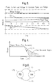
- FIG. 2 illustrates an exemplary plot that may be useful to better understand the principle of efficiency control of synchronous machines.
- the plot of FIG. 2 shows respective exemplary relationships among, input power, phase voltage, magnetizing component of the current, and torque-producing component of the current for a given output torque of a PMAC machine operating under fixed speed conditions.
- the torque-producing current component would need to be varied to keep the output torque constant due to the change of reluctance torque in the machine.
- the parameter variation or input voltage variations are small enough that the change in torque caused by adjusting the flux component of the current with the torque component fixed are negligible and can be performed without significant torque effects.
- the optimal point of operation is seen to occur for the lowest amount of field-weakening current while the required phase voltage is seen to be at its highest value under this condition.
- the techniques discussed in the context of FIG. 1 are believed to fail to provide maximum efficiency at the entire range of operational and/or environmental conditions generally encountered by the propulsion system, and could even lead to instability of the system, particularly in the field-weakening region.
- FIG. 3 shows one exemplary embodiment of the adaptive optimum efficiency control system 100 of the present invention, which for the purposes of analysis and description of its functional interrelationships may be subdivided into three main modules, a compensation look-up table 102, a vector control module 104, and an adaptive control module 106.
- the d axis current reference (I ds *) and the q axis current reference (I qs *) may be adjusted as a function of commanded torque T e * and rotor speed ⁇ r using analytically and/or experimentally derived flux-adjusting values stored in look-up table 102 that may comprise a two-dimensional look-up table responsive to two respective inputs to supply two outputs.
- Look-up table 102 is configured to provide optimum efficiency control for the ideal case by adjusting the value of the d axis current reference (I ds *) and the q axis current reference (I qs *) as a function of commanded torque T e * and rotor speed ⁇ r .
- the value of the torque reference signal T e * may be externally-derived by a system master controller or may correspond to the torque value commanded by an operator through a suitable machine propulsion throttle handle.
- the value of the rotor speed signal ⁇ r may be derived from a rotor angle value ( ⁇ r), upon execution of a mathematical differentiation operation by a differentiator 116 which receives a signal ⁇ r indicative of rotor shaft angle, such as may be generated by a shaft encoder 118.
- the d axis current reference, (I ds *) and an output signal ( ⁇ I ds *) from adaptive control module 106 is each respectively applied to a summer 120 to generate an adjusted.
- d axis current reference signal (Id*) which is further processed by a subtractor 122 that receives a feedback current signal Id.
- the subtracting operation respectively executed by subtractor 122 and other such devices described below may be executed by a summer having one inverting input terminal and one non-inverting input terminal.
- any of the various arithmetic and logical operations in system 100 may be conducted through respective software modules as may be executed in a suitable microprocessor and such operations need not be executed through hardware modules.
- the difference output signal from subtractor 122 represents an error signal between the adjusted d axis current reference signal (Id*) and the feedback current signal Id.
- look-up table 102 one of the outputs of look-up table 102 is the torque-producing current component reference (Iq*), which is processed by a subtractor 124 that receives a feedback current Iq.
- the difference output signal from subtractor 124 represents an error signal between the torque current component reference signal (Iq*) and the feedback current signal Iq. It will be appreciated that look-up table 102 allows for compensating the non-linear torque characteristics of the synchronous machine so as to generate a substantially linear torque response.
- vector control module 104 may comprise a standard RFO vector control system, including respective voltage and current transformation units 126 and 128, two proportional plus integral (PI) current regulators 130 and 132, a voltage limiter and decoupler module 134, each using techniques well-understood by those skilled in the art.
- PI proportional plus integral
- vector control techniques reference is made to Chapters 5 and 6 of a textbook by D. W. Novotny and T. A. Lipo, titled “Vector Control and Dynamics of AC Drives", published by Oxford University Press, 1996, which textbook is herein incorporated by reference.
- the two orthogonal current signals I q and I d in the synchronous frame are respectively applied to the two PI current regulators 130 and 132 as current feedback signals through subtractors 124 and 122.
- the respective outputs of PI regulators 130 and 132 are supplied to voltage decoupling module 134 that removes the effect of cross-coupled flux effects.
- Each respective output signal of voltage transformation unit 126 is then applied to a PWM inverter controller 140 that in one exemplary embodiment may comprise an over-modulation space vector PWM unit to generate three respective duty cycle values.
- the controller functionality is analogous to having six synchronous timers for respectively generating six-gate pulse signals to the respective gate drive circuits of an inverter 142 that energizes synchronous machine 12. It will be further appreciated that the inverter will appropriately switch on and off according to the voltage levels of the gate signals from the controller in order to control operation of the synchronous machine.
- v * s ( ⁇ * ds ) 2 +( ⁇ * qs ) 2
- respective modules 150 and 152 are configured for executing the adaptive control technique of the present invention.
- calculating module 150 allows for executing a voltage index calculation and module 152 allows for executing adaptive control as further described below.
- control module 152 The voltage index value computed based on the foregoing equation is then applied to adaptive control module 152. As suggested above, the output of control module 152 is used to modify the value of the d-axis current reference signal to ensure stable operation of the propulsion system even under demanding operational and/or environmental conditions.
- V_index the magnitude (V_index) of the two orthogonal signals, Vq* and Vd*, which is calculated in calculating module 150 (FIG. 3), is compared or related in module 152, using a comparator 160, to a predetermined voltage threshold value (V_lim) and the output signal from comparator 160 is then coupled to a suitable controller, such as a PI controller 162.
- a suitable controller such as a PI controller 162.
- Controller 162 may be designed to have the dynamic properties mentioned previously so that an appropriate value of an offset signal ( ⁇ I ds_pi ) can be generated and, thus the rotor flux value, under appropriate conditions as determined by a decision logic module 164, would be reduced so that the voltage index magnitude would be reduced to be within the predetermined threshold value.
- the output voltage of the inverter would be kept within the threshold voltage that insures stable operation and optimum efficiency.
- the value of the output signal ( ⁇ I ds_pi ) of controller 162 would be increased until the threshold value is attained assuming that the machine is in the field-weakened range.
- the back EMF would be kept within acceptable design limits and the drive system would be operated at the highest possible efficiency consistent with the voltage limit.
- FIG. 6 is a state diagram as may be executed by decision logic module 164 (FIG. 5).
- Module 164 allows for determining a respective state of operation of the machine and then processes offset signal ⁇ I ds_pi based on the state of the machine. It will be described below that under certain conditions, the full value of the generated offset signal ⁇ I ds_pi is applied to adjust the value of a direct component of stator current command. It will be further described that under other conditions the value of the generated offset signal ⁇ I ds_pi is set to a sufficiently small value (e.g., zero) to leave the value of the direct component of the stator current command substantially unchanged.
- a sufficiently small value e.g., zero
- the output signal from module 164 is labeled in FIG. 5 as ⁇ I ds . Again, this labeling should facilitate the reader's understanding that in some instances the respective output signals from modules 162 and 164 will not be equal to one another.
- state 170 represents machine control in a region without field weakening (NFWR).
- a state transition 172 allows for transitioning to a state 174 (FWR) wherein the machine is controlled in a region with field weakening.
- FIG. 4 illustrates respective exemplary regions with and without field weakening.
- a state transition 176 allows for transitioning back to state 170.
- offset signal ⁇ I ds_pi has a positive value in state 170
- signal ⁇ I ds_pi would be set to a small value, e.g., zero, e.g., the value of signal ⁇ I ds would take a value equal to zero or any sufficiently small value.
- logic module 164 would output the full value of the offset signal, e.g., signal ⁇ I ds_pi would have the same value as signal ⁇ I ds .
- logic module 106 would continue to output the value of ⁇ I ds_pi signal.
- FIG. 7 shows an exemplary flow chart 200 as may be executed by decision logic module 164.
- step 204 allows for calculating the V_index value, such as may be calculated by calculator module 150 (FIG. 3).
- Step 206 allows for calculating the value of the ⁇ I ds signal, such as may calculated by control module 152.
- Step 208 allows for determining a respective control state of the machine, such as state 170 without field weakening or state 174 with field weakening. As suggested above, step 208 further allows for determining whether the machine is transitioning from state 170 to state 174 and vice versa.
- step 210 allows for outputting the offset signal ⁇ I ds , or for setting the value of ⁇ I ds to zero, depending on the respective present state of the machine or the respective state transition that may be occurring.
- FIG. 8 shows another exemplary embodiment of the adaptive optimum efficiency control system 300 that may be suitable for applications with relatively slow changes in the torque command signal. For the sake of avoiding redundancy, functionality of any modules previously discussed will not be repeated.
- a switch 301 is responsive to a switching signal supplied by switch selector 302. During a field-weakened state, switch 301 is set to be connected to terminal 306 to receive a parameter value corresponding to the direct component of stator current command as computed in adaptive control 152.
- This parameter value denoted as Ids_c constitutes a first value of the component of stator current command and, as described above, is based on relating the magnitude of the voltage index against the threshold voltage value.
- switch 301 is set to be connected to terminal 304 to receive a parameter value stored in look-up table 102 that corresponds to the stator current command based on one or more operational signals of the machine, such as commanded torque T e * and rotor speed ⁇ r .
- This parameter value denoted as Ids* constitutes a second value of the component of stator current command.
- switch selector 302 generates a switching signal used for controlling which of the first and second parameter values of the component of stator current command is actually used for machine control. It will be appreciated that the techniques for determining whether the machine is operating either in a field-weakened state, or in a non-field-weakened state are as discussed in the context of FIG. 6 and will not be repeated.
- switch 301 is responsive to the switching signal to pass one of the first and second parameter values based on the respective state of the machine. More particularly, the first parameter value from module 152 is passed through switch 301 from terminal 306 in the presence of the field-weakened state. Conversely, the second parameter value from look-up table 102 is passed through switch 301 from terminal 304 while in the non-field-weakened state.
- the embodiment of FIG. 8, may be conceptually viewed as a hybrid that relies on stored values on the look-up table during the non-field-weakened state, and uses the adaptive techniques discussed in the context of FIGS. 3-7 during the field-weakened state.
- the present invention can be embodied in the form of computer-implemented processes and apparatus for practicing those processes.
- the present invention can also be embodied in the form of computer program code containing computer-readable instructions embodied in tangible media, such as floppy diskettes, CD-ROMs, hard drives, or any other computer-readable storage medium, wherein, when the computer program code is loaded into and executed by a computer, the computer becomes an apparatus for practicing the invention.
- the present invention can also be embodied in the form of computer program code, for example, whether stored in a storage medium, loaded into and/or executed by a computer, or transmitted over some transmission medium, such as over electrical wiring or cabling, through fiber optics, or via electromagnetic radiation, wherein, when the computer program code is loaded into and executed by a computer, the computer becomes an apparatus for practicing the invention.
- the computer program code segments configure the computer to create specific logic circuits or processing modules.
Landscapes
- Engineering & Computer Science (AREA)
- Power Engineering (AREA)
- Control Of Ac Motors In General (AREA)
Abstract
Description
- ieqs(ieds):
- q-axis (d-axis) component of stator current in synchronous reference frame.
- isαs(isβs):
- α-axis (β-axis) component of stator current in stationary reference frame.
- isas (isbs, iscs) :
- a-axis (b-axis, c-axis) component of stator current in stationary reference frame.
- νeqs(νeds):
- q-axis (d-axis) component of stator voltage in synchronous reference frame.
- νsαs(νsβ) :
- α-axis (β-axis) component of stator voltage in stationary reference frame.
- νsas(νsbs, νscs):
- a-axis (b-axis, c-axis) component of stator voltage in stationary reference frame.
- Vdc:
- DC bus voltage.
- Vindex:
- Magnitude of the applied machine voltage
- Vlimit:
- Limit of the allowed voltage applied to the machine
- Vmargin :
- A safety-margin value.
- Vs max:
- Maximum output voltage inverter can provide in SVM.
- Rs:
- Stator resistance.
- Lds:
- Stator D axis Inductance
- Lqs:
- Stator Q axis Inductance
- λeqs (λeds):
- q-axis (d-axis) stator flux vector in synchronous reference frame.
- λeqr (λedr):
- q-axis (d-axis) rotor flux vector in synchronous reference frame.
- ωe (ωr):
- Excitation (rotor) electrical angular frequency.
- e (ϑr):
- Excitation (rotor) electrical angle
- T*e:
- Torque reference of electric machine.
- P:
- Number of poles.
- Variable* :
- Variable reference.
- V*s:
- Voltage vector reference.

Claims (28)
- A method for controlling a synchronous machine (e.g., 12) the method comprising:calculating a stator voltage index (e.g., 204);relating the magnitude of the stator voltage index against a threshold voltage value (e.g., 152);generating an offset signal based on the results of the relating step (e.g., 206);determining a respective state of operation of the machine (e.g., 208); andprocessing the offset signal based on the respective state of the machine (e.g., 210 and 212).
- The method of claim 1 wherein the determining step comprises determining the presence of a field-weakened state, or the presence of a non-field-weakened state.
- The method of claim 2 wherein the processing step comprises applying the value of any generated offset signal to adjust the value of a direct component of a stator current command when the determining step indicates the presence of the field-weakened state.
- The method of claim 3 wherein the processing step comprises setting the value of any generated offset signal to a sufficiently small value to leave the value of the direct component of the stator current command substantially unchanged when the determining step indicates the presence of the non-field-weakened state.
- The method of claim 2 wherein the determining step comprises determining transitioning from the non-field-weakened state to the field-weakened state.
- The method of claim 5 wherein the processing step comprises applying the value of any generated offset signal to adjust the value of a direct component of a stator current command when the determining step indicates the presence of said state transition.
- The method of claim 5 wherein the determining step comprises determining transitioning from the field-weakened state to the non-field-weakened state.
- The method of claim 7 wherein the processing step comprises setting the value of any generated offset signal to a sufficiently small value to leave the value of the direct component of the stator current command substantially unchanged when the determining step indicates the presence of said state transition.
- A method for controlling a synchronous machine (e.g., 12), the method comprising:calculating a stator voltage index (e.g., 204);relating the magnitude of the stator voltage index against a threshold voltage value (e.g., 152);generating a parameter value corresponding to a direct component of a stator current command based on the results of the relating step, said parameter value constituting a first value of said component of stator current command (e.g., 206);providing memory (e.g., 102) configured to store a respective parameter value corresponding to the stator current command based on one or more operational signals of the machine, said parameter value constituting a second value of said component of stator current command;determining a respective state of operation of the machine (e.g., 208); andgenerating a switching signal based on the respective state of the machine, said switching signal used for controlling which of the first and second parameter values of said component of stator current command is to be used for machine control (e.g., 302).
- The method of claim 9 wherein the determining step comprises determining the presence of a field-weakened state, or the presence of a non-field-weakened state.
- The method of claim 10 further comprising providing a switch responsive to the switching signal to pass one of the first and second parameter values based on the respective state of the machine.
- The method of claim 11 wherein the first parameter value is passed when the determining step indicates the presence of the field-weakened state.
- The method of claim 11 wherein the second parameter value is passed when the determining step indicates the presence of the non-field-weakened state.
- The method of claim 9 wherein the one or more operational signals comprise a torque command signal and rotor speed signal.
- A system for controlling a synchronous machine (e.g., 12), the system comprising:a calculating module (e.g., 150) configured to calculate a stator voltage index;a comparator (e.g., 160) configured to relate the magnitude of the stator voltage index against a threshold voltage value;a generating module (e.g., 162) configured to generate an offset signal based on the results of the comparator;a determining module (e.g., 164) configured to determine a respective state of operation of the machine; anda processor (e.g., 164) configured to process the offset signal based on the respective state of the machine.
- The system of claim 15 wherein the determining module is configured to determine the presence of a field-weakened state, or the presence of a non-field-weakened state.
- The system of claim 16 wherein the processor is configured to apply the value of any generated offset signal to adjust the value of a direct component of a stator current command when the determining module indicates the presence of the field-weakened state.
- The system of claim 17 wherein the processor is configured to set the value of any generated offset signal to a sufficiently small value to leave the value of the direct component of the stator current command substantially unchanged when the determining module indicates the presence of the non-field-weakened state.
- The system of claim 16 wherein the determining module is further configured to determine transitioning from the non-field-weakened state to the field-weakened state.
- The system of claim 19 wherein the processor is further configured to apply the value of any generated offset signal to adjust the value of a direct component of a stator current command when the determining step indicates the presence of said state transition.
- The system of claim 19 wherein the determining module is further configured to determine transitioning from the field-weakened state to the non-field-weakened state.
- The system of claim 21 wherein the processor is further configured to set the value of any generated offset signal to a sufficiently small value to leave the value of the direct component of the stator current command substantially unchanged when the determining module indicates the presence of said state transition.
- A system for controlling a synchronous machine (e.g., 12), the system comprising:a calculating module (e.g., 150) configured to calculate a stator voltage index;a comparator (e.g., 160) configured to relate the magnitude of the stator voltage index against a threshold voltage value;a generating module (e.g., 162) configured to generate a parameter value corresponding to a direct component of a stator current command based on the results of the relating module, said parameter value constituting a first value of said component of stator current command;memory (e.g., 102) configured to store a respective parameter value corresponding to the stator current command based on one or more operational signals of the machine, said parameter value constituting a second value of said component of stator current command;a determining module (e.g., 164) configured to determine a respective state of operation of the machine; anda switching control unit (e.g., 302) configured to generate a switching signal based on the respective state of the machine, said switching signal used for controlling which of the first and second parameter values of said component of stator current command is to be used for machine control.
- The system of claim 23 wherein the determining module is configured to determine the presence of a field-weakened state, or the presence of a non-field-weakened state.
- The system of claim 23 further comprising a switch (e.g., 301) responsive to the switching signal to pass one of the first and second parameter values based on the respective state of the machine.
- The system of claim 25 wherein the first parameter value is passed when the determining module indicates the presence of the field-weakened state.
- The method of claim 25 wherein the second parameter value is passed when the determining module indicates the presence of the non-field-weakened state.
- The system of claim 23 wherein the one or more operational signals comprise a torque command signal and a rotor speed signal.
Applications Claiming Priority (2)
| Application Number | Priority Date | Filing Date | Title |
|---|---|---|---|
| US09/757,187 US6407531B1 (en) | 2001-01-09 | 2001-01-09 | Method and system for controlling a synchronous machine over full operating range |
| US757187 | 2001-01-09 |
Publications (2)
| Publication Number | Publication Date |
|---|---|
| EP1221762A2 true EP1221762A2 (en) | 2002-07-10 |
| EP1221762A3 EP1221762A3 (en) | 2004-12-15 |
Family
ID=25046760
Family Applications (1)
| Application Number | Title | Priority Date | Filing Date |
|---|---|---|---|
| EP01204982A Withdrawn EP1221762A3 (en) | 2001-01-09 | 2001-12-18 | Method and system for controlling a synchronous machine over full operating range |
Country Status (2)
| Country | Link |
|---|---|
| US (1) | US6407531B1 (en) |
| EP (1) | EP1221762A3 (en) |
Cited By (1)
| Publication number | Priority date | Publication date | Assignee | Title |
|---|---|---|---|---|
| WO2022048100A1 (en) * | 2020-09-07 | 2022-03-10 | 江苏大学 | Ultra-high-speed electric air compressor variable-voltage stability expansion control system and method for improving large-range speed regulation response capability |
Families Citing this family (49)
| Publication number | Priority date | Publication date | Assignee | Title |
|---|---|---|---|---|
| JP3527207B2 (en) * | 2001-02-16 | 2004-05-17 | 本田技研工業株式会社 | Motor control device |
| US6741060B2 (en) * | 2001-04-05 | 2004-05-25 | Delphi Technologies, Inc. | Method and system for controlling a permanent magnet machine during fault conditions |
| JP4507493B2 (en) * | 2001-07-13 | 2010-07-21 | 三菱電機株式会社 | AC motor speed control device |
| JP3690338B2 (en) * | 2001-11-16 | 2005-08-31 | 松下電器産業株式会社 | Motor control device |
| US6774592B2 (en) * | 2001-12-03 | 2004-08-10 | Delphi Technologies, Inc. | Method and system for controlling a permanent magnet machine |
| US6844701B2 (en) * | 2002-01-16 | 2005-01-18 | Ballard Power Systems Corporation | Overmodulation systems and methods for induction motor control |
| US20040007997A1 (en) * | 2002-07-11 | 2004-01-15 | Visteon Global Technologies, Inc. | Vector control system for permanent magnet sychronous machines using parameter scheduling table |
| JP3914107B2 (en) * | 2002-07-12 | 2007-05-16 | 本田技研工業株式会社 | DC brushless motor control device |
| JP3914108B2 (en) * | 2002-07-15 | 2007-05-16 | 本田技研工業株式会社 | DC brushless motor control device |
| KR20040034908A (en) * | 2002-10-17 | 2004-04-29 | 엘지전자 주식회사 | Driving apparatus of three phase induction motor |
| US20040100221A1 (en) * | 2002-11-25 | 2004-05-27 | Zhenxing Fu | Field weakening with full range torque control for synchronous machines |
| US20040251860A1 (en) * | 2003-01-09 | 2004-12-16 | Mehrdad Ehsani | Advanced sensorless drive technique for brushless DC motors |
| US6876169B2 (en) * | 2003-01-14 | 2005-04-05 | Delphi Technologies, Inc. | Method and controller for field weakening operation of AC machines |
| US6803748B2 (en) * | 2003-02-03 | 2004-10-12 | Delphi Technologies, Inc. | System and method for controlling load dump voltage of a synchronous machine |
| US6864662B2 (en) * | 2003-04-30 | 2005-03-08 | Visteon Global Technologies, Inc. | Electric power assist steering system and method of operation |
| US7276877B2 (en) * | 2003-07-10 | 2007-10-02 | Honeywell International Inc. | Sensorless control method and apparatus for a motor drive system |
| US7262536B2 (en) * | 2003-08-11 | 2007-08-28 | General Motors Corporation | Gearless wheel motor drive system |
| US7242163B2 (en) * | 2003-08-26 | 2007-07-10 | Delphi Technologies, Inc. | System and method for clamp current regulation in field-weakening operation of permanent magnet (PM) machines |
| JP2005219133A (en) * | 2004-02-03 | 2005-08-18 | Fanuc Ltd | Servo motor control device for robot, and robot |
| US7015667B2 (en) * | 2004-03-24 | 2006-03-21 | General Motors Corporation | Current regulation for a field weakening motor control system and method |
| US6940251B1 (en) * | 2004-04-30 | 2005-09-06 | Honeywell International Inc. | Decoupling of cross coupling for floating reference frame controllers for sensorless control of synchronous machines |
| EP1768252B1 (en) * | 2004-07-07 | 2011-01-05 | Hitachi, Ltd. | Motor controlling device for mounting on vehicle |
| US7088077B2 (en) * | 2004-11-09 | 2006-08-08 | General Motors Corporation | Position-sensorless control of interior permanent magnet machines |
| US6965212B1 (en) | 2004-11-30 | 2005-11-15 | Honeywell International Inc. | Method and apparatus for field weakening control in an AC motor drive system |
| WO2006124010A1 (en) * | 2005-05-16 | 2006-11-23 | General Motors Corporation | Current regulation for a field weakening motor control system and method |
| KR100756602B1 (en) * | 2006-06-16 | 2007-09-07 | 인하대학교 산학협력단 | Motor control device and control method of motor control device |
| EP1906423A1 (en) * | 2006-09-29 | 2008-04-02 | ABB Research Ltd | A drive system |
| US7952316B2 (en) * | 2007-04-27 | 2011-05-31 | Honeywell International, Inc. | Variable frequency reduced speed variation electric drive |
| KR101340527B1 (en) * | 2007-05-30 | 2013-12-11 | 엘지전자 주식회사 | Motor Driver System and Controlling Method for the Same |
| FR2919772B1 (en) * | 2007-08-03 | 2010-05-14 | Renault Sas | METHOD FOR CONTROLLING THE POWER SUPPLY OF A THREE-PHASE ELECTRIC MOTOR FROM A CONTINUOUS VOLTAGE SOURCE AND DEVICE FOR CARRYING OUT SAID METHOD |
| US20100066289A1 (en) * | 2008-09-17 | 2010-03-18 | Ford Global Technologies, Llc | System and method for controlling an electric motor |
| KR101199038B1 (en) * | 2008-12-15 | 2012-11-07 | 미쓰비시덴키 가부시키가이샤 | Power converter for driving motor |
| US8198837B1 (en) | 2009-11-23 | 2012-06-12 | Magnetek, Inc. | Device and method for measuring and controlling the speed and torque of a DC motor |
| WO2012014249A1 (en) * | 2010-07-26 | 2012-02-02 | 三菱電機株式会社 | Motor control device and method for controlling motor control device |
| JP5664080B2 (en) * | 2010-09-28 | 2015-02-04 | 日産自動車株式会社 | Motor control device and motor control method |
| KR101209965B1 (en) * | 2010-12-30 | 2012-12-07 | 엘에스산전 주식회사 | System and method for controlling torque of induction motor in electric vehicle |
| CN103503307B (en) * | 2011-04-21 | 2016-01-20 | 日产自动车株式会社 | Motor control device and motor control method |
| FR2976746B1 (en) * | 2011-06-15 | 2015-08-07 | Renault Sa | METHOD AND DEVICE FOR CONTROLLING AN ELECTRIC MOTOR POWERTRAIN WITH DECOUPLED CONTROLS |
| US9209736B2 (en) * | 2011-10-03 | 2015-12-08 | General Electric Company | System and method for traction motor control |
| US8866423B2 (en) | 2012-08-21 | 2014-10-21 | General Electric Company | PMSM field weakening for appliance motors |
| KR101452633B1 (en) * | 2013-05-20 | 2014-10-22 | 엘에스산전 주식회사 | Inverter |
| JP6137086B2 (en) * | 2014-08-19 | 2017-05-31 | 株式会社デンソー | Rotating electrical machine control device |
| JP6217667B2 (en) * | 2015-02-19 | 2017-10-25 | 株式会社豊田自動織機 | Electric compressor |
| US20160276962A1 (en) * | 2015-03-18 | 2016-09-22 | Caterpillar Inc. | Vector Currents Controller for Salient Pole Synchronous Machine |
| EP3382888B1 (en) * | 2017-03-31 | 2020-06-17 | Grundfos Holding A/S | Pump assembly and controlling method |
| US11177748B2 (en) * | 2017-08-29 | 2021-11-16 | Gkn Automotive Ltd. | Field-oriented control of a permanently excited synchronous reluctance machine |
| DE212018000368U1 (en) * | 2017-12-01 | 2020-07-02 | Future Motion, Inc. | Control system for electric vehicles |
| CN110190794A (en) * | 2019-04-12 | 2019-08-30 | 北京航天发射技术研究所 | The calculation method and device of internal permanent magnet synchronous motor given value of current value |
| CN114670656B (en) * | 2020-12-24 | 2024-10-18 | 宁德时代新能源科技股份有限公司 | Control method, device, power system and electric vehicle |
Family Cites Families (22)
| Publication number | Priority date | Publication date | Assignee | Title |
|---|---|---|---|---|
| US3590352A (en) | 1969-04-28 | 1971-06-29 | Square D Co | Field weakening circuit for a series field motor |
| US3656038A (en) | 1970-12-04 | 1972-04-11 | Square D Co | Field weakening circuit for a series field motor |
| BE794885A (en) | 1972-02-04 | 1973-08-02 | Westinghouse Electric Corp | CONSTANT TORQUE CONTROL SYSTEM AND INERTIA COMPENSATION BY REGULATING THE ARMATURE CURRENT AND LOWERING THE EXCITATION OF A DIRECT CURRENT MOTOR |
| US4090119A (en) | 1976-08-12 | 1978-05-16 | General Electric Company | Torque analog of a series wound DC traction motor |
| US4206389A (en) | 1977-02-02 | 1980-06-03 | Clark Equipment Company | Automatic field control for direct current shunt motor |
| DE2755246C2 (en) | 1977-12-12 | 1982-06-03 | Siemens AG, 1000 Berlin und 8000 München | Circuit arrangement for braking a direct current series machine |
| US4131832A (en) | 1977-04-14 | 1978-12-26 | Outboard Marine Corporation | Speed sensitive field weakening control for traction motors |
| US4260937A (en) | 1977-05-16 | 1981-04-07 | Outboard Marine Corporation | Speed sensitive field weakening control for traction motors |
| US4385266A (en) | 1980-03-18 | 1983-05-24 | Technical Operations Limited | Field weakening system for pulse-controlled three-terminal d.c. motor |
| US4675585A (en) | 1984-09-07 | 1987-06-23 | Outboard Marine Corporation | Electric vehicle speed control |
| US4677360A (en) | 1986-03-13 | 1987-06-30 | General Electric Company | Field weakening induction drive |
| US4968925A (en) | 1989-08-07 | 1990-11-06 | General Electric Company | Universal field-oriented controller |
| WO1992001331A1 (en) | 1990-07-13 | 1992-01-23 | Elin Energieanwendung Gesellschaft M.B.H. | Process and circuit for the sensor-less detection of the angle of rotation in a synchronous machine without a damper and preferably excited by a permanent magnet and powered via a converter |
| US5032771A (en) | 1990-08-09 | 1991-07-16 | Allen-Bradley Company, Inc. | Slip control based on sensing voltage fed to an induction motor |
| US6008614A (en) | 1991-03-08 | 1999-12-28 | Honda Giken Kogyo Kabushiki Kaisha | Synchronous motor with permanent magnets and motor system |
| US5455473A (en) | 1992-05-11 | 1995-10-03 | Electric Power Research Institute, Inc. | Field weakening for a doubly salient motor with stator permanent magnets |
| KR950703813A (en) * | 1992-09-24 | 1995-09-20 | 디터 크리스트,하르도 노르트만 | PROCESS AND DEVICE FOR REGULATING A CONVERTER-POWERED, PERMANENTLY EXCITED SYNCHRONOUS MOTOR |
| DE69416747T2 (en) | 1993-08-10 | 1999-07-29 | Toyota Jidosha K.K., Toyota, Aichi | Device for driving and controlling synchronous motors that use permanent magnets as an excitation system |
| US5825113A (en) | 1995-07-05 | 1998-10-20 | Electric Power Research Institute, Inc. | Doubly salient permanent magnet machine with field weakening (or boosting) capability |
| JP3226253B2 (en) * | 1995-09-11 | 2001-11-05 | 株式会社東芝 | Control device for permanent magnet synchronous motor |
| DE19725136C2 (en) * | 1997-06-13 | 2001-01-11 | Siemens Ag | Method and device for current control of a field-oriented, permanently excited synchronous machine with trapezoidal EMF |
| US6014006A (en) * | 1999-06-24 | 2000-01-11 | Ford Global Technologies, Inc. | Induction motor control system with speed and flux estimation |
-
2001
- 2001-01-09 US US09/757,187 patent/US6407531B1/en not_active Expired - Lifetime
- 2001-12-18 EP EP01204982A patent/EP1221762A3/en not_active Withdrawn
Cited By (1)
| Publication number | Priority date | Publication date | Assignee | Title |
|---|---|---|---|---|
| WO2022048100A1 (en) * | 2020-09-07 | 2022-03-10 | 江苏大学 | Ultra-high-speed electric air compressor variable-voltage stability expansion control system and method for improving large-range speed regulation response capability |
Also Published As
| Publication number | Publication date |
|---|---|
| US6407531B1 (en) | 2002-06-18 |
| EP1221762A3 (en) | 2004-12-15 |
Similar Documents
| Publication | Publication Date | Title |
|---|---|---|
| US6407531B1 (en) | Method and system for controlling a synchronous machine over full operating range | |
| Stojan et al. | Novel field-weakening control scheme for permanent-magnet synchronous machines based on voltage angle control | |
| US8519648B2 (en) | Temperature compensation for improved field weakening accuracy | |
| US6741060B2 (en) | Method and system for controlling a permanent magnet machine during fault conditions | |
| Hinkkanen | Analysis and design of full-order flux observers for sensorless induction motors | |
| US6965212B1 (en) | Method and apparatus for field weakening control in an AC motor drive system | |
| US7759886B2 (en) | Linearity for field weakening in an interior permanent magnet machine | |
| US6163128A (en) | Method and drive system for controlling a permanent magnet synchronous machine | |
| US8228016B2 (en) | Gain adjustment to improve torque linearity in a field weakening region | |
| CN100539391C (en) | Synchronous machine control device | |
| EP2963805B1 (en) | Controlling an ac machine | |
| US7592765B2 (en) | Method and system for controlling synchronous motor drive systems | |
| JP5281339B2 (en) | Synchronous motor drive system and control device used therefor | |
| US6876169B2 (en) | Method and controller for field weakening operation of AC machines | |
| CN107592047B (en) | Self-adaptive weak magnetic control method for permanent magnet synchronous motor | |
| US12166437B2 (en) | Method of operating a synchronous motor in a flux weakening mode and a controller therefor | |
| KR20070067118A (en) | Wire rotor synchronous motor control method | |
| JP2001161099A (en) | Control method of synchronous motor | |
| JP4008724B2 (en) | Motor control device | |
| Foo et al. | Robust constant switching frequency-based field-weakening algorithm for direct torque controlled reluctance synchronous motors | |
| CN111277182B (en) | A deep field weakening system of a permanent magnet synchronous motor for vehicles and its control method | |
| JPH08275599A (en) | Control method of permanent magnet synchronous motor | |
| Tolochko | Energy efficient speed control of interior permanent magnet synchronous motor | |
| Zhurov et al. | Modeling of a diesel locomotive induction motor drive with the field-oriented control when operating in a limited voltage and high rotation frequency mode | |
| Fujii et al. | Influence of parameter variations on operating characteristics of MTPF control for DTC-based PMSM drive system |
Legal Events
| Date | Code | Title | Description |
|---|---|---|---|
| PUAI | Public reference made under article 153(3) epc to a published international application that has entered the european phase |
Free format text: ORIGINAL CODE: 0009012 |
|
| AK | Designated contracting states |
Kind code of ref document: A2 Designated state(s): AT BE CH CY DE DK ES FI FR GB GR IE IT LI LU MC NL PT SE TR |
|
| AX | Request for extension of the european patent |
Free format text: AL;LT;LV;MK;RO;SI |
|
| PUAL | Search report despatched |
Free format text: ORIGINAL CODE: 0009013 |
|
| STAA | Information on the status of an ep patent application or granted ep patent |
Free format text: STATUS: THE APPLICATION IS DEEMED TO BE WITHDRAWN |
|
| PUAF | Information related to the publication of a search report (a3 document) modified or deleted |
Free format text: ORIGINAL CODE: 0009199SEPU |
|
| AK | Designated contracting states |
Kind code of ref document: A3 Designated state(s): AT BE CH CY DE DK ES FI FR GB GR IE IT LI LU MC NL PT SE TR |
|
| AX | Request for extension of the european patent |
Extension state: AL LT LV MK RO SI |
|
| RIC1 | Information provided on ipc code assigned before grant |
Ipc: 7H 02P 21/00 B Ipc: 7H 02P 6/06 B Ipc: 7H 02P 6/08 A |
|
| 18D | Application deemed to be withdrawn |
Effective date: 20040701 |
|
| D17D | Deferred search report published (deleted) |