EP1221749A1 - Box for electrical installations, with passive fire protection - Google Patents
Box for electrical installations, with passive fire protection Download PDFInfo
- Publication number
- EP1221749A1 EP1221749A1 EP02004996A EP02004996A EP1221749A1 EP 1221749 A1 EP1221749 A1 EP 1221749A1 EP 02004996 A EP02004996 A EP 02004996A EP 02004996 A EP02004996 A EP 02004996A EP 1221749 A1 EP1221749 A1 EP 1221749A1
- Authority
- EP
- European Patent Office
- Prior art keywords
- shell
- box
- wall
- cavity
- flange
- Prior art date
- Legal status (The legal status is an assumption and is not a legal conclusion. Google has not performed a legal analysis and makes no representation as to the accuracy of the status listed.)
- Granted
Links
- 238000010616 electrical installation Methods 0.000 title claims abstract description 10
- 239000000463 material Substances 0.000 claims abstract description 15
- 239000003063 flame retardant Substances 0.000 claims abstract description 7
- 239000011505 plaster Substances 0.000 claims description 10
- 238000005266 casting Methods 0.000 claims description 2
- 239000000779 smoke Substances 0.000 description 5
- 239000000203 mixture Substances 0.000 description 4
- 229920005830 Polyurethane Foam Polymers 0.000 description 2
- 238000007689 inspection Methods 0.000 description 2
- 238000009434 installation Methods 0.000 description 2
- 238000004519 manufacturing process Methods 0.000 description 2
- 239000002184 metal Substances 0.000 description 2
- 239000011490 mineral wool Substances 0.000 description 2
- 239000011496 polyurethane foam Substances 0.000 description 2
- 239000000843 powder Substances 0.000 description 2
- XLYOFNOQVPJJNP-UHFFFAOYSA-N water Substances O XLYOFNOQVPJJNP-UHFFFAOYSA-N 0.000 description 2
- 229910001335 Galvanized steel Inorganic materials 0.000 description 1
- 239000002657 fibrous material Substances 0.000 description 1
- 239000008397 galvanized steel Substances 0.000 description 1
- 239000011810 insulating material Substances 0.000 description 1
- 239000004570 mortar (masonry) Substances 0.000 description 1
- 238000005192 partition Methods 0.000 description 1
- 239000011470 perforated brick Substances 0.000 description 1
- 239000004033 plastic Substances 0.000 description 1
- 229920003023 plastic Polymers 0.000 description 1
- 239000002023 wood Substances 0.000 description 1
Images

Classifications
-
- H—ELECTRICITY
- H02—GENERATION; CONVERSION OR DISTRIBUTION OF ELECTRIC POWER
- H02G—INSTALLATION OF ELECTRIC CABLES OR LINES, OR OF COMBINED OPTICAL AND ELECTRIC CABLES OR LINES
- H02G3/00—Installations of electric cables or lines or protective tubing therefor in or on buildings, equivalent structures or vehicles
- H02G3/02—Details
- H02G3/08—Distribution boxes; Connection or junction boxes
- H02G3/088—Dustproof, splashproof, drip-proof, waterproof, or flameproof casings or inlets
Definitions
- the present invention relates to electrical installation boxes, such as component boxes and junction boxes, for application to walls, and more particularly their passive fire protection.
- plasterboard walls used for internal partitions of buildings consist of a load-bearing structure (of wood or metal, in particular galvanized steel) faced on both sides with one or more plaster-based boards.
- the boards on the respective sides of the wall bound an interspace into which the service installations (in particular the electrical installation) or insulating material (mineral wool or other fibrous material) can be inserted.
- One solution consists of positioning such boxes on plasterboard walls by firstly making an on-site aperture of suitable dimensions in one of the two sides of the wall, or rather in the board or in the superimposed boards forming one side of the wall.
- the said aperture forms a point of discontinuity, which results in disqualification of the wall with respect to the laboratory-tested prototype.
- a very artisan solution normally used in an attempt to avoid this disqualification consists of preparing a mix of plaster powder, water and mineral wool, which is spread on site over the rear of the box while held in position. When the mix has hardened, a protection shell is obtained which attempts to recreate the conditions of the actual wall without the aperture for the box.
- the protection shell obtained in this manner not only has dimensions which can vary each time, and in particular a thickness which can vary from one point to another, but has to be formed on site before the plasterboard wall is finished (i.e. before the other side of the wall is applied).
- this solution it is not possible to ensure protection of the electric cable exit holes (which in certain situations could constitute a passage for fire and smoke). Again, this solution does not allow inspection once the relative wall is finished.
- such a solution cannot be certified: nobody is able to guarantee, and hence to declare, that the characteristics (in particular the simple dimensional characteristics) of a shell formed on site correspond to a prototype tested in the laboratory.
- the solution using the aforesaid insulating sheets or plates does not however prevent fire or smoke passage through the cable passage holes, unless heat-expanding material is later added in proximity thereto. More generally, all these solutions require a considerable time for their execution, and the result depends very much on the experience and ability of the installer; the result is the impossibility of certifying all these solutions as corresponding to a determined laboratory-tested prototype.
- the object of the present invention is to obviate the aforesaid drawbacks of the solutions of the known art.
- the aforesaid prefabricated shell can conveniently be of plaster or be plaster-based, obtained by casting a relative mix of plaster in powder form, water and possibly other suitable components, in an appropriate form or mould.
- the shell is preferably provided with an edge flange along the opening of its container-shaped body, the flange forming one piece with this body.
- the flange defines a surface which is positioned coplanar with the relative side of the plasterboard wall.
- the flange has an outwardly flared circular outer edge.
- an electric drill can be used in this case, provided with a suitable bit (cup or ring shaped), enabling a flared circular aperture of diameter substantially equal to that of the shell circular flange to be comfortably and quickly formed in the relative side of the wall and in the required position.
- an intumescent fire retardant material is provided within the shell cavity to close the cable passage holes when subjected to the effects of a fire.
- the means for fixing the shell to the wall preferably comprise:
- the through fixing holes provided in the shell flange have a diameter such as to enable an intumescent fire retardant material to be inserted into them, so as to eliminate any possibility of passage for fire or smoke.
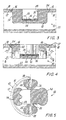
- the box 10 comprises a shell 12 the body 14 of which is formed as a container, which in this specific case (see plan view) is of overall circular shape and presents an open cavity 28.
- the shell 12 also presents a circular edge flange 16 forming one piece with the body 14.
- the flat outer face 15 of the flange 16 is coplanar with the outer face of the board 18 forming the relative outer surface of a plasterboard wall, the opposite outer surface of this wall consisting of a second board 22.
- the boards of the plasterboard wall can also be more than one per side, but this does not constitute a critical element.
- the circular flange 16 has a flared outer edge 17 (see Figures 2-4 in particular) in order to easily mate with the likewise flared edge of a circular aperture 24 previously made in the board 18.
- the circular aperture 24 can be made very easily and quickly using a common professional electric drill provided with a suitable bit (cup or circular ring shaped).
- two through holes 38 are provided in the flange 16 in symmetrical positions corresponding with two symmetrically opposing lateral recesses 32.
- each of the two toggle bolts 50 located in the relative recess 32, comprises a screw 52 with relative washer 58 and a toggle with two foldable arms 54 and 56.
- FIG. 1 clearly shows how the shell 12 is fixed by the toggle bolts 50.
- a split ring (not shown for simplicity) of intumescent fire retardant material can be inserted into the fixing holes 38, it being easily obtained from a commercially available strip of such material, as in the case of the base layer 36.
- Figure 1 shows means 29 for applying the box closure cover (not shown for simplicity) to the shell 12.
- these means can be plastic inserts embedded in the shell 18, to receive the relative screws to maintain the box cover in position.
- the box of the invention being precisely definable in all its characteristics, both dimensional and with regard to the materials used, can be certified by an authorized laboratory and is exactly reproducible.
- the intrinsic simplicity of the aforedescribed and illustrated box is also apparent, as is its ease of production (especially if the shell is formed of plaster or plaster-based material) and the simplicity and speed with which it can be installed, all of which is beneficially reflected in its production and installation costs.
- the use of the box 10 is not limited to plasterboard walls, but that it can be usefully used in all walls in which an aperture can be formed suitable to enable it to be received and be permanently fixed.
- the box can also be used in traditional masonry walls formed from perforated bricks and mortar.
Landscapes
- Engineering & Computer Science (AREA)
- Architecture (AREA)
- Civil Engineering (AREA)
- Structural Engineering (AREA)
- Connection Or Junction Boxes (AREA)
- Installation Of Indoor Wiring (AREA)
- Casings For Electric Apparatus (AREA)
Abstract
Description
- The present invention relates to electrical installation boxes, such as component boxes and junction boxes, for application to walls, and more particularly their passive fire protection.
- As is well known to the expert of the art, plasterboard walls used for internal partitions of buildings consist of a load-bearing structure (of wood or metal, in particular galvanized steel) faced on both sides with one or more plaster-based boards. The boards on the respective sides of the wall bound an interspace into which the service installations (in particular the electrical installation) or insulating material (mineral wool or other fibrous material) can be inserted.
- In compliance with M.I. Circular 91/61, all walls (including plasterboard walls) required to present fire resistance (passive protection) either have to be analytically calculated, or (the case which occurs most frequently in practice) must correspond to a laboratory-certified prototype which generally reproduces a blind wall without openings or holes.
- The problem of passive fire protection for electrical installation boxes (boxes for containing switches, sockets and similar electrical devices, or junction boxes) has been present for a considerable time to the expert of the art, and has involved various solutions, none of which has been found to be completely satisfactory.
- One solution consists of positioning such boxes on plasterboard walls by firstly making an on-site aperture of suitable dimensions in one of the two sides of the wall, or rather in the board or in the superimposed boards forming one side of the wall. As will be apparent, the said aperture forms a point of discontinuity, which results in disqualification of the wall with respect to the laboratory-tested prototype.
- A very artisan solution normally used in an attempt to avoid this disqualification consists of preparing a mix of plaster powder, water and mineral wool, which is spread on site over the rear of the box while held in position. When the mix has hardened, a protection shell is obtained which attempts to recreate the conditions of the actual wall without the aperture for the box.
- Although fairly simple, relatively fast and cheap, this solution is a makeshift solution which presents certain drawbacks. In particular, the protection shell obtained in this manner not only has dimensions which can vary each time, and in particular a thickness which can vary from one point to another, but has to be formed on site before the plasterboard wall is finished (i.e. before the other side of the wall is applied). Moreover with this solution, it is not possible to ensure protection of the electric cable exit holes (which in certain situations could constitute a passage for fire and smoke). Again, this solution does not allow inspection once the relative wall is finished. Finally, such a solution cannot be certified: nobody is able to guarantee, and hence to declare, that the characteristics (in particular the simple dimensional characteristics) of a shell formed on site correspond to a prototype tested in the laboratory.
- In recent years materials have been sought as replacements for said plaster-based mix, such as heat-expanding polyurethane foam or insulating and/or heat-expanding sheets and/or plates Box structures have also been used formed from insulating and/or heat-expanding plates, which are preassembled using metal clips or are to be assembled on site.
- Even these solutions are not however free from drawbacks. In particular, the use of polyurethane foam, being heat-expanding, solves the problem of fire and smoke passage through the cable passage holes, but it again has to be installed before completion of the plasterboard wall, in addition to not allowing future inspection. The same applies to box structures.
- The solution using the aforesaid insulating sheets or plates does not however prevent fire or smoke passage through the cable passage holes, unless heat-expanding material is later added in proximity thereto. More generally, all these solutions require a considerable time for their execution, and the result depends very much on the experience and ability of the installer; the result is the impossibility of certifying all these solutions as corresponding to a determined laboratory-tested prototype.
- The object of the present invention is to obviate the aforesaid drawbacks of the solutions of the known art.
- This object is attained by the electrical installation box according to the present invention, characterised by comprising:
- a prefabricated shell of incombustible material, having a body of open container shape, the shell being embeddable in an aperture previously provided in one side of the wall, the cavity of the shell facing outwards and receiving or being intended to receive the contents of a electrical installation box, the shell presenting cable passage apertures; and
- means for fixing the shell to the wall.
- The aforesaid prefabricated shell can conveniently be of plaster or be plaster-based, obtained by casting a relative mix of plaster in powder form, water and possibly other suitable components, in an appropriate form or mould.
- The shell is preferably provided with an edge flange along the opening of its container-shaped body, the flange forming one piece with this body. The flange defines a surface which is positioned coplanar with the relative side of the plasterboard wall.
- Conveniently, the flange has an outwardly flared circular outer edge. To embed the shell in the plasterboard wall, an electric drill can be used in this case, provided with a suitable bit (cup or ring shaped), enabling a flared circular aperture of diameter substantially equal to that of the shell circular flange to be comfortably and quickly formed in the relative side of the wall and in the required position.
- If the cable passage apertures present in the box body could constitute a passage for fire or smoke, an intumescent fire retardant material is provided within the shell cavity to close the cable passage holes when subjected to the effects of a fire.
- The means for fixing the shell to the wall preferably comprise:
- at least two through fixing holes provided in the shell in opposite positions;
- a toggle bolt cooperating with each hole.
- Preferably the through fixing holes provided in the shell flange have a diameter such as to enable an intumescent fire retardant material to be inserted into them, so as to eliminate any possibility of passage for fire or smoke.
- The invention will be more easily understood from the ensuing description of one embodiment thereof given by way of example. In this description reference is made to the accompanying drawings, in which:
- Figure 1 shows on its left side a front elevation of a box according to the present invention, and on its right side a rear elevation thereof;
- Figure 2 is a section therethrough taken on the line 2-2 of Figure 1, in which part of the lateral boards of a relative plasterboard wall is also visible;
- Figure 3 is a section therethrough taken on the line 3-3 of Figure 1;
- Figure 4 is a section therethrough taken on the line 4-4 of Figure 1;
- Figure 5 shows on its left side a section on the line 5-5 of Figure 4, and on its right side a section on the line 6-6 of Figure 4.
-
- As can be seen from the figures, the
box 10 comprises ashell 12 thebody 14 of which is formed as a container, which in this specific case (see plan view) is of overall circular shape and presents anopen cavity 28. Theshell 12 also presents acircular edge flange 16 forming one piece with thebody 14. As can be seen from Figures 2-4, in which the box is shown installed, the flatouter face 15 of theflange 16 is coplanar with the outer face of theboard 18 forming the relative outer surface of a plasterboard wall, the opposite outer surface of this wall consisting of asecond board 22. It should be noted that the boards of the plasterboard wall can also be more than one per side, but this does not constitute a critical element. - As already stated, the
circular flange 16 has a flared outer edge 17 (see Figures 2-4 in particular) in order to easily mate with the likewise flared edge of acircular aperture 24 previously made in theboard 18. Thecircular aperture 24 can be made very easily and quickly using a common professional electric drill provided with a suitable bit (cup or circular ring shaped). - In the lateral wall of the container-
shaped body 14 of theshell 12 there are provided four through apertures 26 (Figures 3-5) forming the so-called cable passages, through whichapertures 26 there can be passed the electric cables (not shown) to be connected , for example, to the components contained in theopen cavity 28. On theinner bottom surface 34 of thecavity 28 there is provided in this specific case alayer 36 of intumescent fire retardant material the purpose of which, in the case of fire, and if appropriate, is to considerably increase its volume in order to close thecable passage apertures 26, or rather the free space existing between these apertures and the relative electric cables (not shown for simplicity). - To fix the
shell 12 to theboard 18 of the plasterboard wall, two through holes 38 (see Figures 1 and 2 in particular) are provided in theflange 16 in symmetrical positions corresponding with two symmetrically opposinglateral recesses 32. - As is apparent from Figure 2, the
shell 12 is fixed to theboard 18 of the plasterboard wall by using two conventional toggle bolts (Figure 2 shows with dashed lines only the left bolt, indicated overall by 50). Each of the twotoggle bolts 50, located in therelative recess 32, comprises a screw 52 withrelative washer 58 and a toggle with twofoldable arms - Figure 2 clearly shows how the
shell 12 is fixed by thetoggle bolts 50. - A split ring (not shown for simplicity) of intumescent fire retardant material can be inserted into the
fixing holes 38, it being easily obtained from a commercially available strip of such material, as in the case of thebase layer 36. - Figure 1 shows means 29 for applying the box closure cover (not shown for simplicity) to the
shell 12. In particular, these means can be plastic inserts embedded in theshell 18, to receive the relative screws to maintain the box cover in position. - From the aforegoing it is apparent that the box of the invention, being precisely definable in all its characteristics, both dimensional and with regard to the materials used, can be certified by an authorized laboratory and is exactly reproducible. The intrinsic simplicity of the aforedescribed and illustrated box is also apparent, as is its ease of production (especially if the shell is formed of plaster or plaster-based material) and the simplicity and speed with which it can be installed, all of which is beneficially reflected in its production and installation costs.
- It is important to note that the use of the
box 10 is not limited to plasterboard walls, but that it can be usefully used in all walls in which an aperture can be formed suitable to enable it to be received and be permanently fixed. In particular, the box can also be used in traditional masonry walls formed from perforated bricks and mortar.
Claims (10)
- An electrical installation box (10) with passive fire protection, to be applied to walls (18, 22), and comprising:a prefabricated shell (12) of incombustible material, having a body (14) of open container shape, the shell (12) being embeddable in an aperture (24) previously provided in one side of a wall, the cavity (28) of the shell (12) facing outwards and receiving or being intended to receive the contents of a electrical installation box (29), the shell (12) presenting cable passage apertures (26); andmeans (38, 50) for fixing the shell (12) to the wall (18, 22).
- A box (10) as claimed in claim 1, wherein a fire retardant intumescent material (36) able to close the cable passage apertures (26) in case of fire is provided within the cavity (28).
- A box (10) as claimed in claim 2, wherein the fire retardant material (36) is located on the base of the cavity (38)
- A box (10) as claimed in claim 1, wherein the container-shaped body (14) of the shell (12) is of approximately circular external shape when viewed frontally.
- A box (10) as claimed in claim 1, wherein the shell (12) is of plaster or is plaster-based, obtained by casting a relative mix in a suitable form or mould.
- A box (10) as claimed in claim 1, wherein the shell (12) is provided with an edge flange (16) along the opening of the cavity (28), the flange (16) forming one piece with the body (14).
- A box (10) as claimed in claim 6, wherein the flange (16) has a circular outer edge.
- A box (10) as claimed in claim 7, wherein the edge (17) of the flange (16) is flared outwards.
- A box (10) as claimed in claim 1, wherein the means for fixing the shell (12) to the wall (18) comprise:at least two through fixing holes (38) provided in opposite positions in the shell (12);a toggle bolt (50) cooperating with each hole (38).
- A box (10) as claimed in claim 1, wherein means (29) for applying the closure cover are provided.
Priority Applications (3)
| Application Number | Priority Date | Filing Date | Title |
|---|---|---|---|
| EP02004996A EP1221749B1 (en) | 2002-03-06 | 2002-03-06 | Box for electrical installations, with passive fire protection |
| DE60237053T DE60237053D1 (en) | 2002-03-06 | 2002-03-06 | Electrical installation box with passive fire protection |
| AT02004996T ATE475214T1 (en) | 2002-03-06 | 2002-03-06 | ELECTRICAL INSTALLATION BOX WITH PASSIVE FIRE PROTECTION DEVICE |
Applications Claiming Priority (1)
| Application Number | Priority Date | Filing Date | Title |
|---|---|---|---|
| EP02004996A EP1221749B1 (en) | 2002-03-06 | 2002-03-06 | Box for electrical installations, with passive fire protection |
Publications (2)
| Publication Number | Publication Date |
|---|---|
| EP1221749A1 true EP1221749A1 (en) | 2002-07-10 |
| EP1221749B1 EP1221749B1 (en) | 2010-07-21 |
Family
ID=8185441
Family Applications (1)
| Application Number | Title | Priority Date | Filing Date |
|---|---|---|---|
| EP02004996A Expired - Lifetime EP1221749B1 (en) | 2002-03-06 | 2002-03-06 | Box for electrical installations, with passive fire protection |
Country Status (3)
| Country | Link |
|---|---|
| EP (1) | EP1221749B1 (en) |
| AT (1) | ATE475214T1 (en) |
| DE (1) | DE60237053D1 (en) |
Cited By (6)
| Publication number | Priority date | Publication date | Assignee | Title |
|---|---|---|---|---|
| NL1023903C2 (en) * | 2003-07-11 | 2005-01-12 | Cleo Holding B V | Electricity distribution system, has power cable connection part located in region between fire retardant box and casing around distribution rail branch point |
| NL2005933C2 (en) * | 2010-12-29 | 2012-07-03 | Abb Bv | HOLLOW WALL BOX WITH FIRE-RESISTANT INSERT. |
| DE102014108551B3 (en) * | 2014-06-17 | 2015-08-27 | Svt Brandschutz Vertriebsgesellschaft Mbh International | Fire protection for hollow wall boxes |
| GB2624952A (en) * | 2022-11-29 | 2024-06-05 | Intumescent Systems Ltd | Enclosures for electrical appliances |
| GB2625713A (en) * | 2022-11-29 | 2024-07-03 | Hoody Speaker Hoods Ltd | Covers for electrical appliances |
| FR3155376A1 (en) | 2023-11-14 | 2025-05-16 | Legrand France | Fire-resistant accessory to be installed in a flush-mounted box and fire-resistant assembly comprising a flush-mounted box and such a fire-resistant accessory |
Families Citing this family (1)
| Publication number | Priority date | Publication date | Assignee | Title |
|---|---|---|---|---|
| DK3280018T3 (en) | 2016-08-05 | 2020-07-27 | Abb Schweiz Ag | ELECTRICAL INSTALLATION BOX WITH INSERT OF FIRE-INHIBITIVE MATERIAL |
Citations (6)
| Publication number | Priority date | Publication date | Assignee | Title |
|---|---|---|---|---|
| US3995102A (en) * | 1974-01-25 | 1976-11-30 | Raceway Components, Inc. | Insert device for cables |
| DE2834189A1 (en) * | 1978-08-04 | 1980-02-14 | Rigips Baustoffwerke Gmbh | Jacketed electric installation socket - has inner socket separated from outer one by non-flammable, heat foamable substance |
| US4616104A (en) * | 1984-11-16 | 1986-10-07 | Lindsey Travis C | Fire resistant electrical junction boxes |
| US4667840A (en) | 1984-11-16 | 1987-05-26 | Lindsey Travis C | Fire-resistant electrical junction boxes and method of manufacture |
| DE19831384A1 (en) * | 1998-07-14 | 2000-01-20 | Matthias Goepner | Electrical installation for passing electrical cable through dry lined wall using plaster board insert |
| EP1014523A1 (en) * | 1998-12-22 | 2000-06-28 | Legrand | Flush mounted box for dry wall |
-
2002
- 2002-03-06 DE DE60237053T patent/DE60237053D1/en not_active Expired - Lifetime
- 2002-03-06 EP EP02004996A patent/EP1221749B1/en not_active Expired - Lifetime
- 2002-03-06 AT AT02004996T patent/ATE475214T1/en not_active IP Right Cessation
Patent Citations (7)
| Publication number | Priority date | Publication date | Assignee | Title |
|---|---|---|---|---|
| US3995102A (en) * | 1974-01-25 | 1976-11-30 | Raceway Components, Inc. | Insert device for cables |
| US3995102B1 (en) * | 1974-01-25 | 1985-10-08 | ||
| DE2834189A1 (en) * | 1978-08-04 | 1980-02-14 | Rigips Baustoffwerke Gmbh | Jacketed electric installation socket - has inner socket separated from outer one by non-flammable, heat foamable substance |
| US4616104A (en) * | 1984-11-16 | 1986-10-07 | Lindsey Travis C | Fire resistant electrical junction boxes |
| US4667840A (en) | 1984-11-16 | 1987-05-26 | Lindsey Travis C | Fire-resistant electrical junction boxes and method of manufacture |
| DE19831384A1 (en) * | 1998-07-14 | 2000-01-20 | Matthias Goepner | Electrical installation for passing electrical cable through dry lined wall using plaster board insert |
| EP1014523A1 (en) * | 1998-12-22 | 2000-06-28 | Legrand | Flush mounted box for dry wall |
Cited By (8)
| Publication number | Priority date | Publication date | Assignee | Title |
|---|---|---|---|---|
| NL1023903C2 (en) * | 2003-07-11 | 2005-01-12 | Cleo Holding B V | Electricity distribution system, has power cable connection part located in region between fire retardant box and casing around distribution rail branch point |
| NL2005933C2 (en) * | 2010-12-29 | 2012-07-03 | Abb Bv | HOLLOW WALL BOX WITH FIRE-RESISTANT INSERT. |
| EP2472685A1 (en) | 2010-12-29 | 2012-07-04 | Abb B.V. | Hollow wall box with fire resistant insert piece |
| DE102014108551B3 (en) * | 2014-06-17 | 2015-08-27 | Svt Brandschutz Vertriebsgesellschaft Mbh International | Fire protection for hollow wall boxes |
| GB2624952A (en) * | 2022-11-29 | 2024-06-05 | Intumescent Systems Ltd | Enclosures for electrical appliances |
| GB2625713A (en) * | 2022-11-29 | 2024-07-03 | Hoody Speaker Hoods Ltd | Covers for electrical appliances |
| FR3155376A1 (en) | 2023-11-14 | 2025-05-16 | Legrand France | Fire-resistant accessory to be installed in a flush-mounted box and fire-resistant assembly comprising a flush-mounted box and such a fire-resistant accessory |
| EP4556077A1 (en) | 2023-11-14 | 2025-05-21 | Legrand France | Fire-protection accessory to be installed in a flush mounted box and fire-protection assembly comprising a flush mounted box and such a fire-protection accessory |
Also Published As
| Publication number | Publication date |
|---|---|
| ATE475214T1 (en) | 2010-08-15 |
| EP1221749B1 (en) | 2010-07-21 |
| DE60237053D1 (en) | 2010-09-02 |
Similar Documents
| Publication | Publication Date | Title |
|---|---|---|
| US6586679B2 (en) | Electrical junction box for construction panels | |
| US4667840A (en) | Fire-resistant electrical junction boxes and method of manufacture | |
| CA2815721C (en) | Method for providing a fire safe penetration in building element | |
| EP1221749B1 (en) | Box for electrical installations, with passive fire protection | |
| US20060261223A1 (en) | Wall-supporting device | |
| US20150211245A1 (en) | Free-standing form for building a pre-insulated wall and method of building a structure therewith | |
| US20180298605A1 (en) | Fire barrier box for membrane penetrations | |
| KR20090003503U (en) | Drywall with Resilient Channels | |
| JP7301442B2 (en) | panel unit | |
| EP3280018B1 (en) | Electrical installation box with insert of fire retardant material | |
| US20260071424A1 (en) | Device and method for producing and sealing a line feedthrough directly beneath a ceiling | |
| KR102637816B1 (en) | The sound insulation and fire prevention iron box to strengthen and restore sound insulation and fire prevention performance of the box installation part of the lightweight wall | |
| WO1996007043A1 (en) | Supports | |
| KR19990019928U (en) | Panel for assembly building | |
| CA2028929C (en) | Electric junction box/outlet | |
| CN222632641U (en) | Precast concrete block containing wire box, production mould and wall structure thereof | |
| EP2585646A1 (en) | A constructional element, and a method for manufacturing such constructional element | |
| US20060283119A1 (en) | Building unit and method of constructing buildings therewith | |
| KR100354717B1 (en) | Prefabricated Bathroom with the Integrated Wall | |
| EP3724545B1 (en) | A system consisting of a fire safe sealing and an aperture in a floor or a ceiling of a building and a method for sealing an aperture in a floor or a ceiling of a building | |
| GB2449088A (en) | Insulation device for electrical outlets | |
| JPH1189048A (en) | Box for connecting piping | |
| CA3263343A1 (en) | Device and method for producing and sealing a line feedthrough directly beneath a ceiling | |
| EP1835090A2 (en) | Duct element for electric and HPAC installations | |
| JPH0321146Y2 (en) |
Legal Events
| Date | Code | Title | Description |
|---|---|---|---|
| PUAI | Public reference made under article 153(3) epc to a published international application that has entered the european phase |
Free format text: ORIGINAL CODE: 0009012 |
|
| AK | Designated contracting states |
Kind code of ref document: A1 Designated state(s): AT BE CH CY DE DK ES FI FR GB GR IE IT LI LU MC NL PT SE TR |
|
| AX | Request for extension of the european patent |
Free format text: AL;LT;LV;MK;RO;SI |
|
| 17P | Request for examination filed |
Effective date: 20021212 |
|
| AKX | Designation fees paid |
Designated state(s): AT BE CH CY DE DK ES FI FR GB GR IE IT LI LU MC NL PT SE TR |
|
| AXX | Extension fees paid |
Extension state: MK Payment date: 20021212 Extension state: LT Payment date: 20021212 Extension state: LV Payment date: 20021212 Extension state: AL Payment date: 20021212 Extension state: SI Payment date: 20021212 Extension state: RO Payment date: 20021212 |
|
| 17Q | First examination report despatched |
Effective date: 20090504 |
|
| GRAP | Despatch of communication of intention to grant a patent |
Free format text: ORIGINAL CODE: EPIDOSNIGR1 |
|
| GRAS | Grant fee paid |
Free format text: ORIGINAL CODE: EPIDOSNIGR3 |
|
| RAP1 | Party data changed (applicant data changed or rights of an application transferred) |
Owner name: MISURE CONTROLLI SICUREZZA S.AS. DI DAVIDE LURASCH |
|
| RAP1 | Party data changed (applicant data changed or rights of an application transferred) |
Owner name: MISURE CONTROLLI SICUREZZA S.AS. DI DAVIDE LURASCH |
|
| GRAA | (expected) grant |
Free format text: ORIGINAL CODE: 0009210 |
|
| AK | Designated contracting states |
Kind code of ref document: B1 Designated state(s): AT BE CH CY DE DK ES FI FR GB GR IE IT LI LU MC NL PT SE TR |
|
| AX | Request for extension of the european patent |
Extension state: AL LT LV MK RO SI |
|
| REG | Reference to a national code |
Ref country code: GB Ref legal event code: FG4D |
|
| REG | Reference to a national code |
Ref country code: CH Ref legal event code: EP |
|
| REG | Reference to a national code |
Ref country code: IE Ref legal event code: FG4D |
|
| REF | Corresponds to: |
Ref document number: 60237053 Country of ref document: DE Date of ref document: 20100902 Kind code of ref document: P |
|
| REG | Reference to a national code |
Ref country code: NL Ref legal event code: VDEP Effective date: 20100721 |
|
| LTIE | Lt: invalidation of european patent or patent extension |
Effective date: 20100721 |
|
| PG25 | Lapsed in a contracting state [announced via postgrant information from national office to epo] |
Ref country code: AT Free format text: LAPSE BECAUSE OF FAILURE TO SUBMIT A TRANSLATION OF THE DESCRIPTION OR TO PAY THE FEE WITHIN THE PRESCRIBED TIME-LIMIT Effective date: 20100721 Ref country code: FI Free format text: LAPSE BECAUSE OF FAILURE TO SUBMIT A TRANSLATION OF THE DESCRIPTION OR TO PAY THE FEE WITHIN THE PRESCRIBED TIME-LIMIT Effective date: 20100721 Ref country code: NL Free format text: LAPSE BECAUSE OF FAILURE TO SUBMIT A TRANSLATION OF THE DESCRIPTION OR TO PAY THE FEE WITHIN THE PRESCRIBED TIME-LIMIT Effective date: 20100721 |
|
| PG25 | Lapsed in a contracting state [announced via postgrant information from national office to epo] |
Ref country code: PT Free format text: LAPSE BECAUSE OF FAILURE TO SUBMIT A TRANSLATION OF THE DESCRIPTION OR TO PAY THE FEE WITHIN THE PRESCRIBED TIME-LIMIT Effective date: 20101122 Ref country code: CY Free format text: LAPSE BECAUSE OF FAILURE TO SUBMIT A TRANSLATION OF THE DESCRIPTION OR TO PAY THE FEE WITHIN THE PRESCRIBED TIME-LIMIT Effective date: 20100721 |
|
| PG25 | Lapsed in a contracting state [announced via postgrant information from national office to epo] |
Ref country code: BE Free format text: LAPSE BECAUSE OF FAILURE TO SUBMIT A TRANSLATION OF THE DESCRIPTION OR TO PAY THE FEE WITHIN THE PRESCRIBED TIME-LIMIT Effective date: 20100721 Ref country code: SE Free format text: LAPSE BECAUSE OF FAILURE TO SUBMIT A TRANSLATION OF THE DESCRIPTION OR TO PAY THE FEE WITHIN THE PRESCRIBED TIME-LIMIT Effective date: 20100721 Ref country code: GR Free format text: LAPSE BECAUSE OF FAILURE TO SUBMIT A TRANSLATION OF THE DESCRIPTION OR TO PAY THE FEE WITHIN THE PRESCRIBED TIME-LIMIT Effective date: 20101022 |
|
| PG25 | Lapsed in a contracting state [announced via postgrant information from national office to epo] |
Ref country code: DK Free format text: LAPSE BECAUSE OF FAILURE TO SUBMIT A TRANSLATION OF THE DESCRIPTION OR TO PAY THE FEE WITHIN THE PRESCRIBED TIME-LIMIT Effective date: 20100721 |
|
| PLBE | No opposition filed within time limit |
Free format text: ORIGINAL CODE: 0009261 |
|
| STAA | Information on the status of an ep patent application or granted ep patent |
Free format text: STATUS: NO OPPOSITION FILED WITHIN TIME LIMIT |
|
| 26N | No opposition filed |
Effective date: 20110426 |
|
| PG25 | Lapsed in a contracting state [announced via postgrant information from national office to epo] |
Ref country code: ES Free format text: LAPSE BECAUSE OF FAILURE TO SUBMIT A TRANSLATION OF THE DESCRIPTION OR TO PAY THE FEE WITHIN THE PRESCRIBED TIME-LIMIT Effective date: 20101101 |
|
| REG | Reference to a national code |
Ref country code: DE Ref legal event code: R097 Ref document number: 60237053 Country of ref document: DE Effective date: 20110426 |
|
| PG25 | Lapsed in a contracting state [announced via postgrant information from national office to epo] |
Ref country code: MC Free format text: LAPSE BECAUSE OF NON-PAYMENT OF DUE FEES Effective date: 20110331 |
|
| REG | Reference to a national code |
Ref country code: CH Ref legal event code: PL |
|
| GBPC | Gb: european patent ceased through non-payment of renewal fee |
Effective date: 20110306 |
|
| REG | Reference to a national code |
Ref country code: FR Ref legal event code: ST Effective date: 20111130 |
|
| REG | Reference to a national code |
Ref country code: IE Ref legal event code: MM4A |
|
| PG25 | Lapsed in a contracting state [announced via postgrant information from national office to epo] |
Ref country code: FR Free format text: LAPSE BECAUSE OF NON-PAYMENT OF DUE FEES Effective date: 20110331 Ref country code: IE Free format text: LAPSE BECAUSE OF NON-PAYMENT OF DUE FEES Effective date: 20110306 Ref country code: LI Free format text: LAPSE BECAUSE OF NON-PAYMENT OF DUE FEES Effective date: 20110331 Ref country code: CH Free format text: LAPSE BECAUSE OF NON-PAYMENT OF DUE FEES Effective date: 20110331 Ref country code: DE Free format text: LAPSE BECAUSE OF NON-PAYMENT OF DUE FEES Effective date: 20111001 |
|
| REG | Reference to a national code |
Ref country code: DE Ref legal event code: R119 Ref document number: 60237053 Country of ref document: DE Effective date: 20111001 |
|
| PG25 | Lapsed in a contracting state [announced via postgrant information from national office to epo] |
Ref country code: GB Free format text: LAPSE BECAUSE OF NON-PAYMENT OF DUE FEES Effective date: 20110306 |
|
| PGFP | Annual fee paid to national office [announced via postgrant information from national office to epo] |
Ref country code: IT Payment date: 20120227 Year of fee payment: 11 |
|
| PG25 | Lapsed in a contracting state [announced via postgrant information from national office to epo] |
Ref country code: LU Free format text: LAPSE BECAUSE OF NON-PAYMENT OF DUE FEES Effective date: 20110306 |
|
| PG25 | Lapsed in a contracting state [announced via postgrant information from national office to epo] |
Ref country code: TR Free format text: LAPSE BECAUSE OF FAILURE TO SUBMIT A TRANSLATION OF THE DESCRIPTION OR TO PAY THE FEE WITHIN THE PRESCRIBED TIME-LIMIT Effective date: 20100721 |
|
| PG25 | Lapsed in a contracting state [announced via postgrant information from national office to epo] |
Ref country code: IT Free format text: LAPSE BECAUSE OF NON-PAYMENT OF DUE FEES Effective date: 20140306 |