Field of the invention
This invention concerns an information mediating system and
method for mediating information in which numerous information provider
terminals which are capable of outputting data, an information
mediator with a server to extract a specified type of useful
data from these output data, and information beneficiaries who can
derive some benefit from these useful data are connected through a
network. The useful information is mediated between the providers
and the beneficiaries by the server. In other words, this invention
concerns an information mediation system and method to control
the exchange of value-added information between two machines and to
set a price on this mediation service.
Background of the invention
As high-speed information networks have been developed in recent
years, large numbers of terminals with a communication function
have come to be connected to each other through information
networks. Information mediation systems which obtain specified information
from many terminals through this sort of information network
have developed methods whereby a beneficiary initially records
with the mediator what categories or types of information he desires.
The mediator then extracts from the extensive data sent by
the many providers only that information which matches the categories
or types selected by the beneficiary and sends that information
to him. In other words, when the beneficiary records with the
mediator which categories or types of information he wishes to be
sent to him, he enables the mediation to occur. However, in prior
art information mediation systems, the portions of the expenses to
be borne by the persons providing the information and the persons
using the information were fixed. The mediator was not free to reassign
providers or beneficiaries according to the categories and
types of information selected. Thus separate information mediation
systems had to be constructed at great expense for each category or
type of information. In addition, everyone who purchased information
mediation had to pay the same fixed charge.
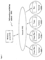
Figure 32 illustrates problems that will occur in the future
as more and more information terminals are connected to a network.
The item labeled "networked terminal 3210" in the drawing is a
prior art terminal connected to a network. Typically, this would
be a personal computer or a portable communication device (i.e., a
cell phone or a mobile communication terminal). These are devices
which the person himself directly operates. Despite much discussion
of the "net society" of the future, the total number of such
devices will not exceed several times the figure for the population.
The item labeled "networked sensing device" 3201 is a device
with a sensing function which is connected to a network. The term
"equipment" in "equipment data sensor" 2302, which is one of the
devices under this rubric, refers to an apparatus which is fixed in
place (i.e., permanently installed) to achieve a given objective.
For example, this might be an automatic vending machine, a machine
in a factory, or a machine installed outdoors, on a street or
bridge. The "equipment data sensor" is a device which acquires
data concerning these types of equipment. Such an equipment data
sensor may in some cases itself be connected to a network. The
item labeled "home data sensor" 3203 is a device which can acquire
sensor data concerning a home. Such sensors might be used on what
are sometimes called "information" home electronics (which are connected
to a network): the TV, the radio, the refrigerator, the air
conditioner, etc., or on home equipment which responds to commands
transmitted through a network: doors, windows, ventilation fans,
the gas, the water, etc. The item referred to as "automotive data
sensor" 3204 is any device which collects data from a sensor in a
car. In some cases it may refer to the car itself which is connected
to the network. So when we compare the potential number of
these devices with that of networked terminals 3210, whose potential
number does not exceed several times that of the population,
we see that there is a vast potential for many more networked sensing
devices 3201 to be used in the future. Since such sensors can
be used without wiring in all kinds of systems, machines and equipment,
their potential number has no relationship with population
figures.
It is already possible to use individual communication devices
on each of the various sensors and components that are used in many
systems. For example, it is already possible to put a communication
device on each of the various sensors in a vending machine.
To monitor the state of the machine, the signals from the various
sensors are sent to a control center via a dedicated line or a PHS.
The salient point here is that in the future, when the current
network to which networked terminals 3210 are connected gives way
to a network to which various sensing devices 3201 are connected,
the number of devices referred to as networked sensing devices 3201
will be vastly greater than the number of devices connected to networked
terminals 3210. To put it another way, although it is true
that there are many, many networked terminals, their potential number
(because they are used by individuals) cannot exceed several
for each person; hence the total would be several times the number
of people in the population. In contrast, networked sensing devices
are not used directly by individuals, so their potential number
is arguably much greater. (It has been estimated to be at the
very least ten or more times the population.) If individual sensors
are connected to the network, their potential number will in
fact be unlimited.
In the near future, then, when large numbers of these networked
sensing devices 3201 come into use, there will be a need for
some sort of traffic control to manage and make use of their data.
One actual scheme to deal with this problem is the "information mediation"
which is the main point of this invention. How to manage
a fee system for the various data obtained by data devices, including
networked sensing devices, will be complicated as the numbers
of such devices explode in the future, as was discussed above.
Many believe that a number of different fee systems will be needed.
There can be no doubt that the current relationship, in which one
terminal furnishes data and another terminal uses it, will give way
to one in which the same terminal can be the provider or the beneficiary.
Thus managing payment for data will also require traffic
control. One actual scheme to deal with this is the "fee mediation"
which is another of the main objectives of this invention.
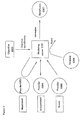
Figure 5 illustrates the problem areas which arise in transferring
information between providers and beneficiaries. When, as
has been discussed, more and more terminals with a communication
capability are connected to each other through a network, there
will be a problem 0501 of lack of awareness of beneficiaries who
would recognize the value of the information. In other words, the
provider does not know who the people (or, in this invention, the
equipment or devices) are who see the information he is providing
as valuable (recognizing the value of the information is equivalent
to being willing to pay for it) and desire to have it. There is
also a problem 0502 of the provider being in the dark as to what
the beneficiary regards as valuable. Even if the provider knows
who the people who want information are, he still hasn't a clue as
to what they value or what they want.
Problem 0503 is the intermixture of valuable and worthless information.
This refers to providing information to a customer
without realizing its value (although the customer does), or to the
provider not knowing that the same information can have a different
value (either higher or lower) to different customers. Problem
0504 is the lack of established rules to compensate providers.
This means that because the seller, as was discussed above, does
not understand the value of the information for which he is supposed
to compensate providers according to the value it has for the
customers, he cannot determine what an appropriate compensation
(i.e., compensation to the providers) would be. The problem does
not disappear if the providers and beneficiaries are linked through
a network, which is, after all, merely a means or tool to transmit
information. The question which is central for this invention is:
what is the principle or concept that will determine how the links
between providers and beneficiaries will be made use of?
As was explained in the aforesaid Figure 32, the society of
the future will have networked sensing devices in numbers so vast
that there can be no comparison with the number of networked terminals
that exist today. In this future society, there will be a
need for traffic control to organize the information from all these
networked sensors and make the maximum use of it. The information
mediation system according to this invention is a system to control
the traffic of this information and by so doing impart an added
value to it and set the charge for that added value.
Summary of the invention
In this invention, the servers owned by the provider and the
mediator of the information, which are linked to each other through
an information network such as the Internet, are on one side. On
the other are the servers for the mediator and the beneficiary,
linked in the same way through a network. The first objective of
this invention is to provide a system and method to mediate information
whereby a person who activates the system inputs a given objective
specification to the mediator's server, and the server mediates
and transmits to the beneficiary out of the mass of information
sent by providers just such information as conforms to that
objective specification, so that a provider and beneficiary for the
information are put together flexibly each time the need arises and
the information traffic is thereby controlled.
With this invention, as was discussed above, each time an interaction
takes place, a combination of information provider and
beneficiary is assembled anew according to the objective specification.
Thus the same terminal may receive compensation as a provider
at one time and be charged a fee as a beneficiary under a
different objective specification at another time. The second objective
of this invention is to mediate the charges to each terminal
by keeping a running total of the payments and fees which accrue
to each customer as an information provider and beneficiary in
the information mediation system according to this invention.
This invention discloses an information mediating system provided
with a plurality of terminals which have both information
sending and receiving functions, or either an information sending
or a receiving function through a network, and provided with an information
mediator which has an information mediating function to
mediate a received information through said network. The information
mediating function is distinguished by the configuration comprising,
1) a grouping function to select an information provider
and an information beneficiary out of the plurality of terminals
according to an objective specification to specify a specific information
to be obtained, and 2) a data transmission function to
transmit the specific information obtained from the selected information
provider, which fulfills the objective specification, to the
selected information beneficiary through the network. Let us use
the example of a given area in which a number of cars are traveling
which can remotely output as sensor data the operating state of
their windshield wipers. The sensor data representing the operating
state of the windshield wipers are equivalent to data indicating
whether it is currently raining in the given area. The sensor
data transmitted to a weather data center which is the information
mediator is stored in the server as rainfall data. A driver who
wishes to know what the weather is in a given area could, for example,
connect to the information mediator's server through the
Internet. In this case, the information mediation system according
to this invention will use the objective specification of wanting
to know what the weather is in a given area as its basis for
determining that every car is a provider and the driver described
above is the beneficiary.
The information is evaluated according to the objective specification,
and the fee processing is processed according to this
evaluation. In this invention, the fee processing includes the
payment of a fee for obtaining the information, and receiving a
compensation for providing the information.
In this invention, the specific information to be transmitted
to the selected information beneficiary is obtained based on a specific
state information of said selected information provider to
represent specific states of the terminal of the selected information
provider. The specific information means the specific state
information, for example, if the windshield wipers are working or
not, or if the car door is locked or not. The specific state information
of the selected information provider can be a sensing information.
According to this invention, the information mediating function
has a data processing function which processes the sensing information
detected at the selected information provider to fulfill
the objective specification, then the data transmission function
transmits the processed sensing information to the selected information
beneficiary through the network. In other words, the information
mediating system, according to this invention, can transmit
the sensing information as it is to the information beneficiary, or
it can transmit the processed sensing information processed by the
data processing function. For example, there are a plurality of
fire alarm sensors to detect fire in a factory. If only one sensor
detects the fire, and the information is transmitted to the information
mediating system, then data processing function will judge
that the sensor should be tested by a maintenance agent, but will
not judge that the fire is occurring. If a plurality of fire sensors
detects the fire at the same time, the data processing function
will notify the fire department without contacting the maintenance
agent. In this case, the data processing function can be expressed
by If-Then style, or it can have a self-learning function.
The information meditating function is further provided with a
data search function to search an outer data base to obtain additional
information to fulfill the objective specification.
The data processing function provided in the information mediating
function processes the sensing information and the additional information
obtained from the outer data base to fulfill the objective
specification, then the data transmission function transmits
the processed sensing information and additional information to the
selected information beneficiary through the network. In other
words, the specific information needed for the information beneficiary
is obtained not only from the internal data base, but also
from the disclosed corporate information in the home page, etc.
through an internet portal side or a direct search. For example,
if the sensing information is about the car troubles of a specific
automobile company, then the information mediating system, according
to this invention, will identify the location of the car in
trouble by GPS, and show the direction to the garage on the car
navigation display for the information beneficiary. The location
of the nearest garage will be obtained by searching the home page
of the garages who can handle the car in the trouble. The access
to the home page can be done through the internet portal sides
which are the specific information sources.
In the information mediating system according to this invention,
the information mediating function has a secondary use function,
which stores the obtained specific information in the information
mediator, searches a secondary specific information out of
the stored specific information according to a secondary objective
specification, and then transmits to a secondary information beneficiary.
The data processing in the data processing function mentioned
above means that the plurality of information obtained from
the information providers are selected or added together in order
to fulfill the objective specification. The value added information
means that more information is added to the plurality of information
obtained.
The information mediating system according to this invention,
further comprises a verification function to verify the plurality
of terminals before the data transmission. This verification is
necessary to verify the data is sent only from the verified terminals.
This is also necessary to verify the data is sent only to
the verified terminals. This verification is done prior to the
transmission of the data. The verification function can identify a
type of the received information based on a verification data assigned
to each terminal.
The information mediating function, according to this invention,
further comprises an objective modification function to create
a modified objective specification which is broken down into a
plurality of understandable detailed conditions for the information
mediator, and the information mediating function mediates the received
information based on the modified objective specification.
The plurality of understandable detailed conditions are, for example,
location condition defining the location by dividing the entire
country of Japan into 10 Km squares, the machine condition defining
the running automobile, the providers condition defined by
the windshield wipers in switched-on state, the determination condition
how to make a conclusion it is now raining based on a predetermined
percentage of switched-on windshield wipers, mapping condition
to display the result on a map, output condition to promptly
output the process information.
The information mediating system according to this invention,
the information mediating function ignores the received information
which does not fulfill the objective specification. This function
is necessary to select the information to fulfill the objective
specification.
The objective specification has a plurality of terminal classification
data to classify the plurality of terminals based on a
layered address of each terminal. The terminal classification data
is, form example, a terminal address for each type of machine, sensor,
and event of transmission. The information mediating system
can select the terminal based on this terminal classification data.
The grouping function selects the information provider and the information
beneficiary out of the plurality of terminals according
to the objective specification
The information mediator can be connected with the plurality
of terminals of the information provider and the information beneficiary
through a single or plurality of networks, or through a
same or different network.
This invention discloses an information mediating system provided
with a plurality of terminals which have both information
sending and receiving functions, or either an information sending
or a receiving function through a network, and provided with an information
mediator which has an information mediating function to
mediate a received information through said network. The information
mediating function is distinguished by the configuration comprising,
1) a grouping function to select an information provider
and an information beneficiary out of the plurality of terminals
according to an objective specification to specify a specific information
to be obtained, 2) a data transmission function to transmit
the specific information obtained from the selected information
provider, which fulfills the objective specification, to the selected
information beneficiary through the network, and 3) a fee
mediation function to pay a compensation to the information provider,
and charge a fee to the information beneficiary, based on a
value of the specific information.
The fee mediation function switches the information provider
and the information beneficiary, and reverses a fee charge direction
to the switched information beneficiary, based on a value of
the mediated specific information in response to different objective
specifications. The fee mediation function is also provided
with an information value evaluation function to evaluate the mediated
specific information which is processed and value added information
by the information mediator, then the data transmission
function transmits the mediated specific information to the selected
information beneficiary through the network. "To switch or
reverse" mentioned above means that, for example, a terminal can be
an information provider until a certain specific time, then the
same terminal becomes an information beneficiary after the specific
time.
The fee mediation function is provided with a fee calculation
function to calculate total fee for each selected information beneficiary,
an information provider extraction function to identify
the selected information provider, a percentage calculation function
to calculate a weight of contribution toward achieving the
specific information, a compensation calculation function to calculate
total compensation for each selected information provider, and
a grand totaling function to offset a total fee to pay as the information
beneficiary and a total compensation to receive as the
information provider, and obtain a grand total for each terminal.
The fee mediation function is provided with different fee tables
depending on the objective specification. The tables can be
fluctuated according to an economy, how many information providers
and information beneficiaries are selected, or a usage purpose of
the specific information and a number of usage at the information
beneficiary. The tables can be also fluctuated according to a
processing level of the specific information, or a sales amount, a
profit, and an expected growth of a business which is related to
the specific information.
The compensation to be paid to the information provider, and a
fee to be paid to the information beneficiary, are recorded in a
memory device provided in each terminal. The memory device is, for
example, IC card, etc..
In the information mediating system according to this invention,
the information mediating function selects a transmission type of
information providers according to the objective specification, out
of monitored transmission which requires monitoring by the information
mediating function, independent transmission which controls a
timing of data transmissions to the information mediator by itself,
and event transmission which transmits data only when an unforeseen
accident or breakdown occurred, and the information from the information
providers are sent to the information mediator according to
the selected transmission type.
This invention discloses an information mediating system provided
with a plurality of terminals which have both information
sending and receiving functions, or either an information sending
or a receiving function through a network, and provided with an information
mediator which has an information mediating function to
mediate a received information through said network. The information
mediating function is distinguished by the configuration comprising,
1) a grouping function to select an information provider
and an information beneficiary out of the plurality of terminals
according to an objective specification to specify a specific information
to be obtained, 2) a data transmission function to transmit
the specific information obtained from the selected information
provider, which fulfills the objective specification, to the selected
information beneficiary through the network. The selected
information beneficiary has a maintenance order function to automatically
order a maintenance service to a maintenance agency based
on the received specific information in order to conduct the maintenance
service for a specific terminal of the information provider.
The maintenance service means, for example, to supply the coins for
change in an automated vending machine if the remaining amount becomes
low.
According to this invention, the selected information beneficiary
has a security order function to automatically order a security
service to a security agency based on the received specific
information in order to conduct the security service for a specific
terminal of the information provider when the specific information
contains an abnormal or malfunction information. The security service
means, for example, to notify the security company if an abnormal
vibration is detected in the vending machine.
The detailed explanation for the information meditating method
used in the information mediating system is disclosed in the following
sections.
Brief description of the drawings
Figure 1 is a block diagram showing the entire system according
to this invention.
Figure 2 is a block diagram showing the entire system according
to this invention.
Figure 3 is a block diagram showing the entire system according
to this invention.
Figure 4 is a conceptual diagram which illustrates the meaning
of a provider, a beneficiary and information which has a value.
Figure 5 is a conceptual diagram setting forth the problem areas
regarding the information transmitted between providers and
beneficiaries.
Figure 6 is a conceptual diagram to illustrate the mediation
performed by information mediator.
Figure 7 is a flow chart which illustrates the basic role
played by the aforementioned mediator.
Figure 8 is a flow chart which illustrates the basic role
played by the aforementioned mediator.
Figure 9 is a block diagram illustrating the actual process by
which the mediator mediates information.
Figure 10 is a conceptual diagram to illustrate in a more concrete
manner the fee mediation function performed by the mediator.
Figure 11 gives a conceptual diagram illustrating the standard
by which the value of information is judged.
Figure 12 gives a conceptual diagram illustrating the standard
by which the value of information is judged.
Figure 13 is a realistic example which illustrates the distinctive
features of the information mediation system related to
this invention, in which the same machine or device may be both a
provider and a beneficiary, depending on the objective.
Figure 14 is a chart showing how the flow of information is
organized when there are two different objectives.
Figure 15 compares the information mediation system according
to the current invention, which achieves the aforesaid objective,
with the scheme used in the prior art.
Figure 16 gives an example of one machine or device which is
pursuing a number of objectives.
Figure 17 shows an example in which a single machine or device
can, in the information mediation system related to this invention,
change its role when an event occurs.
Figure 18 is a block diagram illustrating the information mediation
system according to this invention.
Figure 19 is a block diagram giving an example of fees and
compensation that might accrue in an information mediation system
according to this invention.
Figure 20 is a block diagram giving an example of fees and
compensation that might accrue in an information mediation system
according to this invention.
Figure 21 is a block diagram which illustrates how the objective
specification is processed in the information mediation system
according to this invention.
Figure 22 is a block diagram of functions which represent the
means by which the objective specification is broken down.
Figure 23 is a block diagram which illustrates how the objective
specification is processed in the information mediation system
according to this invention.
Figure 24 is a block diagram which illustrates how the objective
specification is processed in the information mediation system
according to this invention.
Figure 25 is a block diagram which illustrates how the objective
specification is processed in the information mediation system
according to this invention.
Figure 26 is a block diagram which illustrates how the objective
specification is processed in the information mediation system
according to this invention.
Figure 27 is a block diagram illustrating the machine verification
process.
Figure 28 is a block diagram illustrating the processing executed
to confirm the identity of the machine.
Figure 29 gives an example of the verification data.
Figure 30 gives an example of the verification data.
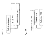
Figure 31 shows a sample configuration for the verification
data.
Figure 32 illustrates problems that will occur in the future
as more and more information terminals are connected to a network.
Figure 33 is a comprehensive diagram of the aforesaid information
mediation system related to this invention.
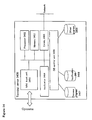
Figure 34 is a block diagram of the hardware in verification
server.
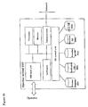
Figure 35 is a block diagram of the hardware in the objective
specification server.
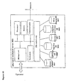
Figure 36 is a block diagram of the hardware in mediation
server.
Figure 37 is a block diagram of the hardware in the fee mediation
server.
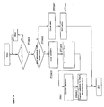
Figure 38 is a flow chart for the operation unit in verification
server.
Figure 39 is a flow chart of the main routines in the operation
unit of objective specification server.
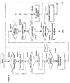
Figure 40 is a flow chart of the main routines in the operation
unit of objective specification server.
Figure 41 is a flow chart of the processing executed by the
operation unit of mediation server.
Figure 42 is a flow chart of the processing executed by the
operation unit of mediation server.
Figure 43 is a flow chart of operations executed by the operation
unit of fee mediation server.
Figure 44 is a block diagram showing the aforesaid servers'
DBs and the flow of processing in the servers.
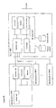
Figure 45 is a block diagram of the hardware in machine or device.
Figure 46 is a block diagram of the hardware in another preferred
embodiment of the machine or device.
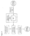
Figure 47 is a functional block diagram for the machine or device.
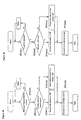
Figure 48 is a flow chart of the operation unit in a machine
or device.
Figure 49 is a flow chart of the operation unit in a machine
or device.
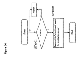
Figure 50 is a flow chart of the operation unit in a machine
or device.
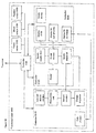
Figure 51 is a detailed example of the special functions discussed
in Figure 45.
Figure 52 is a detailed example of the special functions discussed
in Figure 45.
Figure 53 is an additional illustration concerning the control
units in Figures 51 and 52.
Figure 54 is a flow chart to execute objective A in Figure 13.
Figure 55 is a flow chart to execute objective A in Figure 13.
Figure 56 is a flow chart to execute objective A in Figure 13.
Figure 57 is a flow chart to execute objective B in Figure 13.
Figure 58 is a flow chart to execute objective B in Figure 13.
Figure 59 is a flow chart to execute objective B in Figure 13.
Figure 60 is a realistic example of the machine or device for
the beneficiary shown in Figure 57 through Figure 59.
Figure 61 is a realistic example of the machine or device for
the beneficiary shown in Figure 57 through Figure 59.
Figure 62 is a realistic example of the machine or device for
the beneficiary shown in Figure 57 through Figure 59.
Figure 63 is a realistic example of the machine or device for
the beneficiary shown in Figure 57 through Figure 59.
Figure 64 is a realistic example of the machine or device for
the beneficiary shown in Figure 57 through Figure 59.
Figure 65 is a realistic example of the machine or device for
the beneficiary shown in Figure 57 through Figure 59.
Figure 66 is a realistic example of the machine or device for
the beneficiary shown in Figure 57 through Figure 59.
Figure 67 is a block diagram of the hardware in machine or device.
Figure 68 is a block diagram which illustrates the flow of information
between the DBs for the various servers and the memory
medium.
Figure 69 is a flow chart of the example shown in Figure 68.
Figure 70 is a flow chart of the example shown in Figure 68.
Figure 71 is a flow chart of the example shown in Figure 68.
Figure 72 shows a sample appearance of a machine or device.
Figure 73 is a flow chart of the processing for objectives C
and D in Figure 16.
Figure 74 is a flow chart of the processing for objectives C
and D in Figure 16.
Figure 75 is a flow chart of the processing for objectives C
and D in Figure 16.
Figure 76 is a flow chart of the processing for objectives C
and D in Figure 16.
Figure 77 is a block diagram illustrating how the data flows
among the DBs.
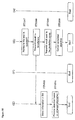
Figure 78 shows an example of the secondary use of information.
Figure 79 is a block diagram of the processing executed to
modify the objective specification in Figure 78.
Figure 80 is a flow chart of the processing executed when a
potential beneficiary specifies an objective as in the aforesaid
Figure 78.
Figure 81 is a flow chart of the processing executed when a
potential beneficiary specifies an objective as in the aforesaid
Figure 78.
Figure 82 is a flow chart of the processing executed when the
mediator solicits potential secondary beneficiaries in Figure 78.
Detailed description of the invention
Comprehensive Block Diagrams of Providers, Beneficiaries, Mediator
and Objective
The providers, beneficiaries, mediator and objective specification
discussed above in regard to the information mediation system
relating to the aforesaid invention are shown in block diagram
in Figures 1 through 12 and shall be disclosed in detail in the
following section.
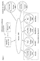
Figure 1 is a block diagram showing the entire system according
to this invention. It is a comprehensive diagram of information
mediation system 0001 to mediate information through its
server 0101 between equipment or devices 0103 to 0106, which are
all connected to network 0102.
The function (or method) of receiving and transmitting data
which inheres in the equipment or devices 0103 to 0106 here described
may be implemented remotely or by wire. As long as they
are connected to a network, the type and arrangement of these devices
is of no importance. Equipment or devices 0103 to 0106,
which are connected through network 0102 to the mediator's server
0101, are divided into three classes. 0103 and 0104 can both send
and receive data; 1015 can only send data; and 0106 can only receive
data.
The role of the information mediator's server 0101 in this
configuration is to acquire information from equipment or devices
selected from its options according to the objective it receives,
and then to transfer some of this information, selected according
to the objective, to equipment or devices selected from its options.
This transfer of information which fulfills an objective is
what we refer to as "information mediation." The entity which is
capable of mediating information (in the example, the server which
performs the information mediation) is what we refer to as the "information
mediator."
Figure 2 is a comprehensive diagram of a system which illustrates
how information is mediated for a particular objective (in
the drawing, objective A 0201). By connecting to the information
mediator's server 0101 for objective 0201, the equipment or devices
0103 to 0106 that are within the dotted lines, namely the same
equipment and devices pictured in Figure 1, begin to participate in
the system. In this case, devices 0202 and 0203 do not share objective
0201, but are connected to the network. These devices,
however, may be participating in the system with objectives other
than objective A. A single device is not restricted to a single
objective, but may participate in the system with a number of different
objectives. A crucial consideration for this invention is
that a device which participates with a number of different objectives
may at some times be a provider and at other times a beneficiary.
Even with the same objective, a single device may play both
roles at different times. The circumstances under which a device
becomes a provider or beneficiary will be explained later in
another diagram.
Figure 3 is a comprehensive diagram in which Figure 2 has been
visualized in another way. This diagram illustrates the different
types of providers. The mediation capability of information mediator
0101 consists of determining what role each device will play
according to the objective 0201 which it receives in order to
achieve the image shown in the diagram. The interaction in which
mediator server 0101 receives objective 0201 is what we refer to as
"objective specification." Normally, objective specification will
be initiated by a beneficiary 0307 who wants to obtain some specific
information. However, it need not be limited to the beneficiary.
A third party may also specify an objective. When specifying
an objective to mediator server 0101, the beneficiary may input
to server 0101 a number of objectives of various types which define
what sort of information he needs.
The information providers may be divided into three classes:
Data transmitted by equipment or device 0306, which does not
contribute to fulfilling this objective, are ignored by the mediator.
It is of course possible that this device may be participating
with some other objective, and so may be a provider or beneficiary
in terms of that objective, a situation not pictured in this
diagram. For the sake of convenience, let us assume that the devices
in the diagram have no other objectives. In the information
mediation system according to this invention, different providers
will participate for each objective 0201.
Figure 4 is a conceptual diagram which illustrates the meaning
of a provider 0401, a beneficiary 0402 and information which has a
value. In this diagram, the information which has a value is valued
information 0403. This term refers to information which the
information-using party (here, beneficiary 0402) is willing to pay
fee 0404 to obtain, or to valued information 0403 which is yet to
be acquired. The provider and beneficiary are defined as provider
0401 and beneficiary 0402 in relation to the valued information.
The value here is that perceived by the recipient, beneficiary
0402. It is set according to the subjective evaluation of the recipient,
the party who will use the information. Thus the value of
the information as perceived only by provider 0401 has no effect on
this value.
Since the entity we have been calling "information beneficiary
0402" is in actuality a machine or device, the "subjective evaluation"
will depend on whether the information increases the usefulness
of the machine or device. To put it another way, "information
which will add value," i.e., information which increases the usefulness
of the machine or device, is any information which the
beneficiary values to the extent that he is willing to pay for it.
Fee 0404, which beneficiary 0402 pays to obtain the information,
becomes profit for the provider. Accordingly, there will come to
be an industry of providing information for a fee. We might consider
the relationship between this information and its value to be
an equivalence, i.e., the information itself can be considered to
be equivalent to a value: it is a value-equivalent item. Or we
might consider that there is a value which is inherent within the
information (or with which the information has been vested): it is
information which possesses an inherent value. The "objective"
which has been discussed in the drawings up to this point is defined
as the acquisition of information of value to the beneficiary,
i.e., information which he values.
We have already explained that this invention concerns an information
mediation system which brokers information between providers
and beneficiaries, and that this information mediation
system imparts an added value to the information as it controls its
traffic. In the absence of an information mediation system such as
that provided by this invention, the transmitters and receivers of
the information would both experience great confusion in trying to
deal with it, as will be described shortly. Figure 5 is a conceptual
diagram setting forth the problem areas regarding the information
transmitted between providers and beneficiaries as explained
in Figure 4.
The information provider possesses information which he has
generated, procured or accumulated; yet in the absence of an appropriate
means to control its traffic, he will be unable to identify
potential beneficiaries who will recognize its value, he will have
no knowledge about beneficiaries who do recognize its value, and he
will have no rules governing how fees are to be assessed. Thus his
"information" will not be information in the true meaning of the
word. Being unable to identify potential beneficiaries means that
the provider of the information has no idea who the customers (with
this invention, machines or devices) are who will recognize the
value of the information he wants to provide and so will want it.
(Recognizing the value of the information is synonymous with being
willing to pay a fee.) Having no knowledge about the beneficiaries
who do recognize the value of the information means that even when
the provider knows who the customers who want the information are,
he is still in the dark as to what exactly they value and what it
is they want. Having valuable and worthless information intermixed
means providing information to a customer without determining its
value (as perceived by that customer), or not being aware that the
same information can have a different value (either higher or
lower) when provided to a different customer. Not having rules to
govern fee assessment means that because the seller, as was discussed
above, does not understand the value of the information for
which he is supposed to compensate providers according to the value
it has for the customers, he cannot determine what an appropriate
compensation (i.e., compensation to the providers) would be. The
problem does not disappear if the providers and beneficiaries are
linked through a network, which is, after all, merely a means or
tool to transmit information. The fact that a potential provider
who has information and a potential beneficiary who needs that information
are linked through a network does not translate into a
profitable relationship in the absence of appropriate traffic control.
The Mediator
We have been discussing the chaotic situation which occurs
when there is no mediator, as illustrated in Figure 5. Figure 6 is
a conceptual diagram to illustrate the mediation performed by information
mediator 0601, which is the main objective of this invention.
The mediation performed by the mediator has two functions:
function 0602, information mediation, and function 0603, fee mediation.
We shall generally use "mediation" to refer to both functions
together. However, we will at times for the sake of convenience
use "mediation" with its narrow meaning of information mediation.
In discussing Figure 6, we shall expand our explanation and
add details with reference to Figures 7 through 12.
The Mediator and the Information Mediation Function
In Figure 6, mediation function 0602 refers to selecting information
obtained from provider 0604 according to the objective
obtained either directly or indirectly from beneficiary 0605 and
transmitting only that information which provider 0604 regards as
valuable. In other words, this function consists of selecting and
transmitting information. In some cases, the mediator may collect
information before it is classified according to an objective. Mediation
function 0603 refers to distributing to the providers, according
to the value of the information provided, the fees paid either
directly or indirectly by the beneficiaries. Beneficiary 0605
in this case may also refer to many beneficiaries. In other words,
all machines or devices which pay a fee to obtain the information,
even if it is the same information, may be considered beneficiaries.
Figure 7 is a flow chart which illustrates the basic role
played by the aforementioned mediator. We shall begin by discussing,
with reference to the flow chart, the basic steps in the
mediation
function 0602 performed by the mediator illustrated in Figure
6. This mediation function consists of the following.
In other words, the information mediation function is put into
play when an objective is specified (i.e., when objective specification
occurs). The objective here is what the beneficiary (a machine
or device) specifies for the mediator to use. It is the purpose
for which the information will be used as seen by the beneficiary.
We shall next discuss mediation function 0602.
The objective in the first function, "Receiving the objective,"
may be conveyed directly by the beneficiary or indirectly by
a third party. The third function, "Acquiring information from the
providers," corresponds to the step in the flow chart where it is
determined whether information has been provided by the providers.
Note that although the mediator's server is receiving various kinds
of information from all the machines and devices connected to the
network, it will determine that information it receives from devices
other than those selected as providers in function 2 does not
serve the purpose, and it will not mediate it. In other words, the
server ignores information which does not conform to the objective.
The providers are those machines and devices which absolutely conform
to the objective. We might say that the providers are those
devices which the mediator sees as absolutely certain to be related
to the objective.
In function 6, "Transmitting the information which conforms to
the objective to the beneficiaries," the mediator determines, when
it receives information from a provider, whether that information
conforms to the objective it has received. It then transmits to
the beneficiaries (as information conforming to the objective) only
that information which it judges to conform to the objective.
We shall next discuss the flow of the actual mediation function
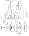
0602 as illustrated in the flow chart in Figure 7. In the
first step, information mediator 0601 in Figure 6 determines in
Figure 7 whether objective specification has occurred (0701). If
it has, the mediator selects providers and beneficiaries from the
available machines and devices connected to the network according
to the objective it has received (0702). It then stores in its
memory unit a set of objective data containing the objective and
the results of the selection (0703). In a separate procedure, the
mediator checks whether information has been provided by any providers
(0704). It reads out of the memory unit any potential target
information from a provider who has sent information (0705),
and it determines whether the information provided conforms with
the stated objective (0706). If it does conform with the objective,
the mediator transmits the target information to the beneficiaries
(0707). If in (0706) the information does not conform with
the objective, the mediator stores it in the memory unit along with
the target information as "acquired information" (0708) and stands
by until more information is provided (0704).
The mediator checks to see whether the stated objective has
been completely fulfilled (0709). If it has, the mediator stores
the information it has transmitted in the memory unit along with
the target information as "objective fulfilled" information (0710).
It cancels the completed objective and stores the result in the
memory unit (0712). The mediation processing is now completed. If
in 0709 the objective has not been completely fulfilled, the mediator
stores the information it has transmitted in the memory unit
along with the target information as "transmitted information"
(0711) and stands by for more information from providers (0704).
The Mediator and the Fee Mediation Function
In the above discussion, we explained the information mediation
function (0602) shown in Figure 6. We shall next explain the
fee mediation function (0603) in the same way. Figure 8 is a flow
chart illustrating the basic role played by the mediator. We shall
begin by discussing the fundamental aspects of this fee mediation
function with reference to the flow chart.
The fee mediation function can be broken down into the following
functions.
The fee mediation function 0603 in Figure 6, then, is the final
step in the process instigated when a customer specifies an objective
(i.e., when objective specification occurs). The "value"
referred to above is related to the objective agreed upon by the
beneficiary (a machine or device) and the mediator.
When the fee to be charged to the beneficiary is determined in
function 1 above from the value of the information transmitted, its
value for a given objective is already known. If there are multiple
beneficiaries, the value of the information to each will be determined
from factors both intrinsic and external to the machine or
device which specifies the objective (these factors will be explained
in a separate diagram) with reference to the various objectives
to which the information is tied. The total charge calculated
for each beneficiary from the value assigned to each
objective becomes the beneficiary fee for that beneficiary. The
fee charged for using the mediation service is not included here.
When the percentage of the fee to go to the provider is calculated
in function 2 above according to the value of the information
acquired, the percentage is determined from the value. A provider
who supplies more valuable information will be given a greater percentage
of the fee.
When the compensation is determined in function 3 from the
percentage that was decided on, the beneficiary fee and the compensation
are not necessarily equal. In general, the compensation
will equal the beneficiary fees minus the mediator's expenses (viz,
operating cost and profit).
To determine the total compensation for each machine or device
in function 4 based on the fees and compensation that were decided
on, the mediator has to offset the compensation against the beneficiary
fees (internal processing executed by the mediator). This is
necessary because the same machine or device may, for different objectives,
function at different times as both a provider and a
beneficiary.
When the compensation which was determined is stored in the
memory unit in function 5, it becomes the data which serves as a
basis for processing fee assessment. Actually, since both the providers
and beneficiaries are machines, there will be many cases in
which human operators take part in the information mediation system.
These operators will specify (i.e., input) objectives to the
information mediator's server and settle the charges (i.e., they
will pay any shortfall or receive any excess). The "operators" may
be humans, or they may be terminals (machines or devices) which
convey a human's wishes.
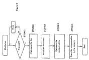
The block diagram in Figure 8 explains each step of the aforesaid
fee mediation function 0603, which was discussed in detail in
the aforesaid functions 1 through 5. In Step 0801, the mediator
checks whether information has been sent to the beneficiary (as in
0707 or 0710 in Figure 7). It calculates the beneficiary fee for
each beneficiary based on the value of the information which was
sent, in this way determining all the beneficiary fees.
In Step 0803, the mediator extracts from the memory unit all
the providers who have furnished information which was sent to
beneficiaries. In Step 0804, it determines the compensation to be
paid to each provider by calculating his percentage based on the
value of the information he has provided.
In Step 0805, the mediator calculates the total charge and
compensation which has been decided for each machine or device, and
stores these in the memory unit. This completes the fee mediation
processing. The last step constitutes the aforesaid functions 4
and 5.
Block Diagram of Mediator and Information Mediation Function
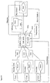
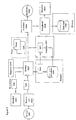
Figure 9 is a block diagram illustrating the actual process by
which the mediator mediates information in the aforesaid Figure 6.
Each block corresponds to a portion of the flow in Figure 7. This
diagram covers what happens from the time the information is input
until it is output. The portion of Figure 9 which is enclosed
within dotted lines represents information mediation function 0602
and corresponds to function 0602 in Figure 6.
First, some specified sensing data from a sensor installed on
a machine or device 0901 are input via an information network to
mediation function 0602 in the information mediation system according
to this invention. The information from machine or device 0901
is not limited to sensing data only. It includes all input data
concerning specific states which can occur in that device or machine.
These input data are first sent to function 0902, the processing
of acquired data. This function consists of receiving data
from a device or machine. The input data are then sent to function
0903, the sorting process. This process consists of comparing the
data received in the acquisition function with a previously stored
objective 0920 and sorting them accordingly. Data which do not
conform to the objective are sent to function 0904, cancellation
processing, where they are cancelled. Data which are judged in the
sorting process to fulfill the objective are sent without further
processing via function 0905, data transmission, to beneficiaries
for whom they have a value. Data which in the sorting process are
judged not to fulfill the objective are stored in memory unit 0906,
which serves as a data base. They may be combined in function
0907, combination processing, with other data received in the future
to form a data group, which will be sent via function 0905,
data transmission, to beneficiaries 0930 for whom these data have a
value. Function 0907, combination processing, refers to combining
newly received data with data stored in the data base to create information
which has a value. "Creating information which has a
value" is equivalent to creating information which conforms to an
objective. In some cases, data which did conform to an objective
may be combined with other data to increase their value. In such
cases, we could say that the data are being given a new value.
When the data which match the objective specification are sent
to beneficiaries 0930, they are also sent in parallel to function
0908, which determines that a single objective has been achieved or
an entire set of objectives is completed. Function 0908 consists
of determining whether the objective which was specified has been
achieved and whether the process is now completed. The result of
this processing is used in the fee mediation function, which will
be discussed shortly. Objectives which are judged to have been
fulfilled are communicated to function 0909, cancellation processing,
where they are cancelled.
Function 0910, storing the data for objectives that are
achieved and completed, consists of storing data for objectives
0920 judged in function 0908 to have been achieved or completed,
together with the provider, viz., the machine or device 0901 which
furnished the data, and beneficiary 0930, the machine or device
which will use the data.
Figure 10 is a conceptual diagram to illustrate in a more concrete
manner the fee mediation function 0603 performed by the mediator
in Figure 6. Figure 10 corresponds to the flow in Figure 8,
which means that it covers what happens from the time the objective
is achieved until the compensation is processed. The functions enclosed
within dotted lines represent fee mediation function 0603.
In the final stage of the mediation processing shown in Figure
9, the mediator stores the data for which mediation processing has
been completed in function 0910, which is part of the mediation
function. First, the value of these stored data is judged by function
1002, value determination processing, which is a component of
fee mediation function 0603. Function 1001 (sic; in diagram, 1002)
consists of determining the value of the data for achieved or completed
objectives which have been sent to beneficiaries. The actual
compensation or fee is computed by function 1003, calculating
the fee and compensation, which consists of calculating the fee for
each objective and, if there are multiple beneficiaries, totaling
the fees to obtain the fee to be charged.
To extract data concerning the party which has furnished the
data when the mediation processing is completed, we move to the
processing in function 1004, the extraction of the provider. This
function consists of extracting from the data stored by the mediation
function (see Figure 9) in data base 0906 the name of the provider
who furnished the data for which a fee is assessed. In function
1005, processing is executed to calculate the percentage for
compensation purposes. This function consists of obtaining, for
each provider (i.e., each machine or device) extracted by function
1004, a percent rating to indicate the weight of the contribution
made by the data it provided toward achieving or completing the objective.
The compensation and fee, i.e., the payment based on the cost
price that is made to the provider in the commercial transaction
known as mediation and the fee for providing the information which
the beneficiary is charged are processed by function 1006, calculating
the charges. This function consists of calculating the
amount each provider is to be charged from the total fees calculated
by the fee calculation function (in reality, the total fees
after the mediator's profit margin is subtracted) and the compensation
percentage calculated for each provider by the percentage calculation
function. Function 1007 is the final calculation of the
charge. It consists of executing the processing to compute a total
charge (including offsetting fees and compensation) for each machine
or device for which a fee was calculated by the fee calculation
function and compensation was calculated by calculation function
1006 (since the same device can at different times be both a
provider and a beneficiary). The result is transmitted to function
1007, storing the total charge. This function consists of storing
the total charge calculated for each machine or device by the
charge totaling function.
Figure 11 gives a conceptual diagram illustrating the standard
by which the value of information is judged. This is an example of
a standard which might be used when function 1002 in Figure 10, the
evaluation function, determines the value of the information. The
standard for determining value can be divided into two questions:
"How much labor was required on the seller's part to provide this
information?" and "How attractive is this information to the
buyer?"
Since information is deemed valuable insofar as it fulfills an
objective (See Figures 7 and 9), its assumed value is determined
when that objective is specified. The value determined at the time
the objective is specified is called its "fixed component." Different
information will be valued differently depending on how difficult
it was for the providers selected by the mediator for a
given objective to acquire it, how carefully the mediator selected
information from the total data set he acquired, and how much the
information was processed to enhance its value. The portion of the
value which varies depending on how the objective is achieved is
called its "variable component." There may be cases in which the
charge is discounted for a frequent beneficiary in order to reduce
the beneficiary fee which would ordinarily increase with frequency
of use. The beneficiary might also anticipate that by using the
information he will increase its value. (This translates into the
beneficiary feeling that what he is being charged for the information
provided might not be appropriate or reasonable.) All of
these factors are diagrammed in Figure 12. The factors which go
into determining the value of information are divided into two
classes: factors which pertain to the seller (i.e., the mediator),
and factors which pertain to the buyer (i.e., the beneficiary). In
this regard, information is no different from any other product.
The factors pertaining to the seller may be divided into factors
which yield a fixed value, which is determined when the objective
is specified; and factors which govern the variable aspect of the
value, which may be revised when the objective is fulfilled. This
aspect of the information's value varies depending on how difficult
it turned out to be for the providers to acquire it, how carefully
the mediator selects information to match the objective, and how
much the information is processed to enhance its value. Factors on
the buyer's side which cause the value of the information to vary
include his belief that the value of the information will be enhanced
by the fact that he is using it; and his frequency of use,
which if high can result in a discount. The value of the information
is thus determined in function 1002 in Figure 10 by taking all
of these factors into consideration.
Reversing the Flow of Information by Changing Objectives
The information mediation system relating to this invention is
distinguished by the fact that the role played by any of the aforesaid
terminals can switch from that of provider to that of beneficiary
in response to different objectives. For example, when a
given event occurs, the party which until that point had been the
provider can become the beneficiary. Let us given an example in
which the aforesaid terminal is a vending machine. Normally, the
vending machine is a provider, transmitting data to the mediator's
server at regular intervals to report sales figures. When event
data are generated reporting that the machine is out of change or
that the stock of soda cans is low (a sudden change of state),
these sensing data are transmitted to the mediator's server as an
event so that the change or the soft drinks can be restocked. The
event transforms the vending machine, which until that point had
been a provider, into a beneficiary.
To given another example of this invention, the mediator, in
addition to selecting terminals according to the objective which is
specified, creates a timetable for connecting to the said terminals
which varies with the objective. It can change the priority it assigns
to connecting to a given terminal to accord with the urgency
or the frequency which an objective requires. For information
which is more urgently needed, the mediator may schedule connection
on demand. For information which is less urgent, it may collect
information from the terminal when free time is available so as to
accommodate the load on the network.
The aforesaid timetable according to this invention may also
permit interrupts for certain kinds of specified objectives or certain
kinds of signals input by terminals. In other words, information
from a provider which is very urgent or important to the beneficiary,
as was explained above, can be assigned a high priority by
giving it a schedule that allows interrupt processing.
The aforesaid timetable may be revised if the value of the
data input by a terminal changes. For example, the timetable which
schedules connecting to a terminal may be changed after an event
occurs. For some objectives, the aforesaid mediator, who is aware
of the characteristic profile of each terminal, may select a timetable
which permits interrupts so that it can conduct a poll based
on those characteristics.
Actual Example 1
We shall next give a detailed disclosure of the distinctive
features of the objective and objective specification in the information
mediation system related to the aforesaid invention, with
reference to the examples in Figures 13 through 18.
Figure 13 is a realistic example which illustrates the distinctive
features of the information mediation system related to
this invention, in which the same machine or device may be both a
provider and a beneficiary, depending on the objective. In this
example, there are three cars, car 1301, car 1302 and car 1303, on
a highway. Each car has a sensor built into its windshield wipers
to detect whether the current state of the wipers is "on" or "off."
These on-off states are transmitted remotely, for example via the
internet, to mediator server 1304. If we look at car 2, for example,
we see that its role varies depending on the objective. (It
is a provider with respect to objective A but a beneficiary with
respect to objective B.) The arrows in the drawing indicate in
which direction the information is flowing to the mediator's server
with respect to each objective. Let us call one of the cars which
are traveling (i.e., which are now on the road) in area 1 "car 1,"
and let us assume that car 1 and car 2 are going in the same direction.
Objective A could, for example, be "Find out where it is raining
right now in Japan," and the beneficiary could be the server
for a weather information center. Objective B could be "Find out
if traffic is backed up," and the beneficiary could be car 2. When
the mediator's server receives objective A, it might extract a
given number of cars, say one to several, from a ten-mile-square
area. The sensors in, say, cars 1 through 3 would detect whether
or not their wipers were turned on (because it was raining), and
the area where it was raining would be transmitted to the server at
the weather information center. The information transmitted might
then be mapped. (This is an example of the processing mentioned in
Figure 11.) In this case all three cars are providers.
When it receives objective B, the information mediator's
server might extract a given number of cars, say one to several,
from all the cars going the same direction as car 2. It would
measure their average speed (and in some cases determine whether
traffic was backed up) and transmit the result of the measurement
to car 2. Thus in the example shown here, the mediator obtains the
speed sensor data from car 1, which is ahead of car 2, and uses
these data as a basis to determine whether the traffic is backed
up, which is objective B. Here car 1 is the provider, just as it
was for objective A; but car 2 has changed roles and is now the
beneficiary. For the aforesaid objective B, we can imagine various
kinds of value-added information which might be transmitted. The
average speed on an alternative route could be measured (from cars
on that route) and a recommendation could be made. (I.e., the
quickest route could be calculated from the average speed and the
distance.) The fee might also be increased so that the beneficiary
pays according to how useful the value-added information is. The
machines or devices that are the providers and beneficiaries, then,
simply exchange information with the information mediator's server,
while the server is responsible for everything involved in the information
(and the fee).
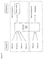
Figure 14 is a chart showing how the flow of information is
organized when there are two different objectives, as was discussed
above, and the same terminal (here, a car) can be a provider with
respect to one objective and a beneficiary with respect to the
other. For objective A in Figure 13, cars 1, 2 and 3 and all the
other cars in the target area are providers, and only the weather
center is the beneficiary. For objective B, car 1 and the other
cars in the target area are the providers and car 2 is the beneficiary.
In this way the same device, like car 2, can go from being
a provider to being a beneficiary depending on the objective.
Figure 15 compares the information mediation system according
to the current invention, which achieves the aforesaid objective,
with the scheme used in the prior art. The bottom half of the
drawing represents the existing scheme. For the providers, dedicated
sensors 1502 through 1504 were installed in place in various
locations to obtain the desired data for the information provider's
server 1501. This scheme required a system which did nothing but
collect information, and it required beneficiaries 1301 through
1303 to go to some lengths to access the information. The beneficiary
himself had to surf the net and search a number of data bases
to obtain the information he needed. In this example, the providing
sensors 1502 through 1504 would be dedicated sensors installed
before the system was operational, which might include a speed sensor,
a raindrop sensor and a road surface sensor. The data obtained
from these stationary data sources would generally be processed
and organized before they were provided to the beneficiaries.
In other words, in the existing information mediation system, the
role of provider or beneficiary, once assigned, cannot be changed.
The information mediation system related to this invention is
pictured in the upper half of the drawing. Each machine (piece of
equipment or device: here, cars 1301 through 1303) is connected to
a network and has in it various sensors as well as output devices
to transmit the information. These onboard sensors and output devices
exchange information with the server 1304 for the information
mediation system constantly or as needed. Each machine is assigned
a role for each objective so that it can obtain or use the information
it or someone else needs. The actual server 1304 for information
mediation corresponds to mediator's server 0101 in Figures 1
through 3. We shall give examples of how these devices might be
realized in later diagrams.
Actual Example 2
In the discussion above each beneficiary had a single objective.
However, the information mediation system according to this
invention is not limited in this way. It is possible to imagine a
single beneficiary with numerous objectives. Figure 16 gives an
example of one machine or device which is pursuing a number of objectives.
Machines 1601 through 1603 in the drawing are vending
machines. Each machine contains various sensors to monitor its internal
state. The data detected by these sensors are transmitted
to the information mediator's server, 1304, by a built-in transmitting
function. There are a number of objectives which are agreed
upon by the mediator's server and the controller's server. For example,
objective C might be to detect when the machine is out of
change or to detect how much is left (when there is only a small
amount left). When the supply of change falls below a given
amount, the server is contacted. Objective D might be to detect an
external shock (as a deterrent to theft or other crime).
Since objectives C and D differ in both how frequently they
will be met and how urgent they are (naturally objective D is extremely
urgent), the charge for each of them (according to the concept
explained in Figure 12) will be different. When it receives
the data representing the state of the machine, the role of controlling
server 1605, the beneficiary in this case, is to inform or
notify the human who stocks the machine or the security guard.
When the information is transmitted accurately (swiftly and correctly),
its value (i.e., the meaning it has) is enhanced. Accordingly,
the controlling server recognizes the value in the information
being transmitted accurately (swiftly and correctly), and a
payment schedule is established to set the fee to be paid to server
1304.
Actual Example 3
Figure 17 shows an example in which a single machine or device
can, in the information mediation system related to this invention,
change its role when an event occurs (i.e., when its state
changes). In that figure, car 1301 is normally (i.e., until an
event occurs) a provider for another objective, objective C. When
an event occurs (in the example, a collision with another car), it
becomes an indirect beneficiary who receives a service (objective
E) from the auto club. Since its normal objective A is to report
what the weather is wherever it goes, as is shown in Figure 13, car
1301 normally acts as a provider by continuously transmitting the
on-off state of its windshield wipers to the information mediation
system, as was explained above. Objective E in this example is invoked
only in the event of an accident. If car 1301 is involved in
an accident, the information mediator's server 1304 contacts the
server 1701 for the direct beneficiary, a service agency, to inform
them about the accident. The premise of objective E is that car
1301 has been involved in an accident with another car. At the moment
when the information that an unexpected event has occurred
(i.e., the event data) is transmitted to the information mediator's
server 1304 and help is obtained, car 1301 is transformed from a
provider (reporting the on-off state of its windshield wipers) to
an indirect beneficiary who receives rescue service from the direct
beneficiary, the service agency. Here the term "service agency" is
used to mean the party who responds to the provider's change of
state: an emergency highway crew, the police, the paramedics (or
an ambulance). In this example, when the service agency's server
1701 receives word that an accident has occurred in line which fits
the criteria of objective E, it communicates with its terminal
1702, and a service vehicle is dispatched to car 1301. In the example
in Figure 13, car 1302 went from provider to beneficiary by
changing its objective. In Figure 17, the car changes roles because
of circumstances.
Figure 18 is a block diagram illustrating another scheme to
realize the aforesaid information mediation system according to
this invention. This configuration corresponds to the example
shown in Figure 16. When specified objective 1802 is input or communicated
to the mediator's server 1304, the server begins to receive
information from the providers which conforms to that objective.
Objective 1802 would be either of objectives C and D in Figure
16. The mediator selects the means by which information is to
be obtained from providers. He may, for example, obtain information
from provider 1803 by polling it; from provider 1804 on the
basis of demand; and from provider 1805 on the basis of an event
occurring. Only the information which conforms closely to the
stated objective 1802 will be sent to beneficiary 1806. In Figure
16, beneficiary 1806 is the owner of controlling server 1605. Upon
receiving the information, beneficiary 1806 instructs service
agency 1807 and security agency 1808 to take a specific action.
Here "service agency 1807" is the party which provides maintenance
service. "Maintenance service" refers to overseeing and maintaining
the machine in working condition and repairing it. For the
vending machines in Figure 16, the service agency would be the person
who restocks the change or the juice, cigarettes or other product.
The "security agency" is the party who provides security service.
"Security service" refers to protecting the safety of the
machine or device from external threats and keeping the machine out
of danger. (This includes the idea of prevention.) In the example
in Figure 16, the security agency would be the security company responsible
for the safety of the machine. In some cases, the service
and security agencies (i.e., their servers and terminals) may
be the direct beneficiaries. Figure 17 gives an example of the
service agency's server being the beneficiary.
Enhancement of the specific information fulfilling the objective
specification / generating a value added information
The specific information which fulfills the objective specification
in example 1 through example 3 shown above are transmitted
to the information beneficiaries after relatively low level information
processing. The processing here means how much the information
is processed to enhance the added value shown in Figure 11.
In example 1, mediator's server 1304 judges by itself if it is
raining in the area based on the ON/OFF state information of windshield
wipers of the cars running in the area. The mediated information
obtained from the judgment is then transmitted to the
weather center, or running other car which is an information beneficiary.
On other words, mediator's server 1304 executes a relatively
low level processing which guess the weather based on the
On/OFF state information of the windshield wipers of the running
cars. In example 2, mediator's server 1304 receives the sensor
data for output from the vending machine shown in Figure 16. Based
on the received sensor data, the server judges theft or out of
change state is occurring at the vending machine and judges if the
server should notify the maintenance agent or the security agent.
These judgments are relatively low level processing. In example 3,
mediator's server 1304 only judges if an accident occurred based on
the output data of the shock sensor provided in the running cars.
If an accident has occurred, then the sever will notify the maintenance
agent.
The information mediating system according to this invention
is not limited in the relatively low level processing for the input
data, but also it executes the relatively high level processing.
In the relatively high level processing the mediator's server executes,
there is an internal high level processing to process the
received data internally, and an external high level processing to
process the received data by searching the external data base
through the internet. In the internal high level processing, mediator's
server 1304 has enough software in the server which can
mediate the received information according to the objective specification
(for example, objective specifications A through E), and
the optimal information which meets to the objective specification
is transmitted to the information beneficiary. In the external
high level processing, the mediator's sever searches the necessary
information by accessing the portal site which makes it easy to access
the information sources, and by accessing the home pages of
the corporations. By accessing external data base, the external
high level processing obtains the optimal information for the information
beneficiary.
Actual example 4
Figure 83 and Figure 84 are the block diagrams for the internal
and external high level processing respectively. In this information
meditating systems, sensor 1 through sensor n and a display
device (for example, CRT) are connected to mediation server
3600. The direction of the information flow is reversed by changing
the objective specification as mentioned above.
In the internal high level processing shown in Figure 83, the
mediation server 3600 receives a plurality of sensor outputs, for
example, representing the state information within a factory. The
server, then, can judge what is happening in the factory, and optimal
information is obtained in optimal judging functional unit
8301 using the internal knowledge data base (DB 3604 in Figure 36).
The obtained optimal solution is displayed on the display unit for
the information beneficiary. For the optimal solution, the different
weights can be added to the output data from each sensor, and
it can be expressed by If-Then still according to the optimization
theory in the prior arts. The details of this theory are omitted.
Self-learning functions can be added to the optimization theory in
order for leveling up the mediating system.
Actual example 5
In the external high level processing shown in Figure 84, the
mediation server 3600 receives a plurality of sensor outputs, for
example, representing the state information within a factory. The
server, then, can judge what is happening in the factory, and optimal
information is obtained in optimal judging functional unit
8301 using the internal knowledge data base (DB 3604 in Figure 36),
and the external data base. The obtained optimal solution is displayed
on the display unit for the information beneficiary. In
this processing, the first judgment is obtained based on the internal
knowledge data base, then the sever will access to the portal
site and the home pages of the corporation specialized to the objective
specification for the second judgment. This arrangement
can make it possible to expand the closed information loop of the
internal data base to the open information loop, and it will bring
the more optimal information for the information beneficiary. The
advantage of this external high level processing is that the sensors
function as an information provider, and the mediating server
expands the search area to the external data base through the external
portal site, etc in order to obtain the optimal information
which fulfills the objective specification. In such external high
level processing, mediating server can have a business control to
select the portal sites to be connected. Because many portal sites
wish to be connected to the mediating server, the mediator may be
able to charge a connection fee to the portal sites. This will
create a new business chance for the information mediator.
The situation in which various services are provided based on
information which conforms to an objective specification is equivalent
to the generation of added value in Figure 11. If high-end
services are generated, this will result in higher fees being paid
to the mediator's server. In the following section we shall discuss
in detail how these fees are processed.
Fee Assessment
We shall now explain in greater detail the distinguishing features
of the charge or fee assessment performed by the information
mediation system related to the aforesaid invention, with reference
to Figures 19 and 20.
Figure 19 is a block diagram giving an example of fees and
compensation that might accrue in an information mediation system
according to this invention. The graph shows the total charges for
cars 1301, 1302 and 1303 and server 1305 for the weather information
center in the aforesaid Figure 13. Car 1301 is a provider
with respect to both objective A and objective B. Since it contributed
to fulfilling both objectives, it is credited with two
payments 1901. These payments are the compensation for providers;
they are referred to as "compensation" in Figure 10. The "charge"
is the fee assessed beneficiaries. It is referred to as a "fee" in
Figure 10.
In the same graph, car 1302 has earned a payment for providing
the mediator's server with weather data but has incurred a fee with
respect to objective B for obtaining data concerning the road conditions
where car 1301 was then traveling. Its total charge is
calculated as 1902. This charge is arrived at by offsetting the
compensation against the fee. Car 1303 contributes only to fulfilling
objective A, so it accrues a payment 1903. Server 1305 for
the weather information center acts only as a beneficiary with respect
to objective A, so it incurs a fee. These charges may also
include the information mediator's fee, which would cover his expenses
and profit margin.
Figure 20 uses the same principle to graph the charges incurred
by server 1605, which controls the devices in Figure 16, the
example with vending machines. The controlling server receives the
benefits of being a double beneficiaries since it participates with
respect to objectives C (service) and D (security). It therefore
incurs two charges, which are totaled to arrive at fee 2001. We
can see from the graph that different fees are assessed for the two
objectives. In this example, the fact that "security" costs more
than "service" is due to the beneficiary's different perceptions of
their importance (because of urgency, the potential magnitude of
the loss, etc.). To put it another way, the information that the
vending machine has been shocked and is damaged is more valuable
than the more usual information that it is out of change. The mediator
therefore decides before entering into a contract with the
beneficiary that he will have to pay more for it. In the example,
the server which controls the machines charges a fee for the service;
however, this fee may go toward the upkeep of the server. If
at the same time this server incurs fees for services provided by
other servers, it may end up being charged as a beneficiary.
The Scheme to Process Specifying the Objective
As was discussed above, in the information mediation system
according to this invention, when the mediator specifies an objective
its server vets and selects data from the data base contributed
by all the providers. The actual means by which this selection
is performed is described in detail in Figures 21 through 26.
In a related process, the machine or device must also confirm the
selection; this process will be discussed somewhat later with reference
to Figures 27 through 31.
Figure 21 is a block diagram which illustrates how the language
of the specification is processed in the information mediation
system according to this invention using a data base of knowledge.
We shall give a concrete example of "objective specification"
(i.e., the specification of an objective to the mediator) using
objective 0301, which was discussed in Figure 3. Let us use
objective A in Figure 13 as a concrete example of objective 0301.
Objective A consists of fulfilling the request to find out where it
is raining right now in Japan.
In the diagram, the objective as specified is labeled "2101,"
and the objective which has been modified through the mediator's
internal processing is labeled "2102." The modification consists
of the specified objective being broken down, with the help of the
knowledge data base, which will be discussed shortly, into conditions
defining the location, the machines, the providers, how the
determination is to be made, how the information is to be processed,
and how the information is to be output. An example of the
means by which these objectives might be realized is given in Figure
22.
Figure 22 is a block diagram of functions which represent the
means by which the objective specified in the aforesaid Figure 21
is broken down into a series of objectives for the mediator's convenience.
This diagram represents a portion of the functions executed
by the mediator's server 0302 according to this invention
which is shown in Figure 3.
Initiator 2201 is the party who gives the mediator, or more
specifically, the mediator's server, an objective. The initiator
may be either a device or a person. In some cases, the fee for the
service may be charged not to the beneficiary, but to the initiator.
The initiator and beneficiary may be the same person or device,
or they may be different persons or devices. For example, a
car maker may, as the initiator, wish to find out when a car made
by them is broken down on a given highway; but the beneficiary may
be a local towing business. Of course, the initiator and beneficiary
may be the same person. For example, as is shown in Figure 13,
the driver of car 1302 in zone 2 on the highway may specify the objective
of finding out what the weather is like ahead of him in
zone. He is then both the initiator and the beneficiary.
Reception function 2202 consists of receiving the objective
from initiator 2201. If the objective is to be received through a
network, the system should have the capability to receive signals.
Knowledge recorder 2203 is the party which stores the knowledge
data necessary, for example, to modify the specified objective
shown in Figure 21 for the mediator's use. 2203 may be either a
device or a person who provides knowledge data to the mediator.
Knowledge processing function 2204 consists of storing the knowledge
data provided by knowledge recorder 2203 in the knowledge data
base. This function also entails determining whether a given item
should or should not be stored.
Knowledge storing function 2205 consists of storing the knowledge
data which recording function 2204 judged to be necessary.
Objective modification function 2206 consists of processing the
specified objective, using the knowledge stored in data base 2205,
to create the modified objective. More specifically, it entails
creating the conditions shown in Figure 21.
Party 2207, the person or device that inputs the verification,
inputs data that will allow the mediator to confirm that the connection
is legal, which it needs to do even though the machine or
device is connected to it through a network. The verification may
be transmitted to the mediator by either a machine or a person.
The verification function will be discussed in detail in a later
section. Verification function 2208 consists of confirming that
the connection is legal based on the verification data transmitted
by party 2207. By "verification" is meant checking to make sure
that the conditions are met which permit the mediator and the machine
or device to be connected to each other through the network.
This verification is necessary to insure that only those terminals
which have permission are allowed to connect to the information mediation
system according to this invention. Such terminals will be
either providers or beneficiaries in the system.
Data storage function 2209 consists of storing the data confirming
the identity of the machine or device which were processed
by verification function 2208. Extraction function 2210 consists
of extracting (as shown in Figure 2) the machines or devices stored
in data base 2209 of confirmed devices which are best suited to be
providers and beneficiaries with respect to the objective modified
by function 2206. Data storage function 2211 consists of storing
the providers and beneficiaries extracted by function 2210 along
with the objective modified by the modification function.
Figures 23 through 26 are block diagrams giving a specific example
of how a specified objective is modified. These figures show
the specification of objective B in Figure 13. As was discussed
earlier, "objective specification" refers to providing an objective
to the mediator. The specified objective is broken down into a
number of conditions, and the data transmitted by providers is
matched against each one. Each condition is a unit of data stored
in the objective data base by data storage function 2211. The conditions
could also be considered the individual criteria by which
information is judged. Let us say, for example, that the speed at
which cars are traveling on a given highway is the information coming
from the providers. The data provided in Figure 23, then, are
the speeds of the cars. These data are used to calculate the average
speed. When the specified objective is modified, it is broken
down into criteria which can be matched against data associated
with the average speed.
The direction the beneficiary (a car) is going, which must be
detected as the pre-processing condition, can be calculated from
the point the car has moved to after a given period of time; however,
if the car is parked the beneficiary can be asked directly to
furnish the information (by transmitting the question, "Where do
you want to go?"). In the example in Figure 23, the specified
objective, "I want to find out right now if the traffic is backed
up in the direction I'm going," is divided into three parts: "I
want to find out right now," "if the traffic is backed up," and "in
the direction I'm going." These parts are broken down into a pre-direction
I'm going." These parts are broken down into a pre-processing
condition, a location condition, a machine condition, a
condition for the information to be provided, a condition for
evaluation, and an output condition, all of which are stored as
units in the data base for function 2205 in Figure 22 and sent to
selection function 2212 for the next stage of processing.
Figure 24 is a block diagram giving as a specific example the
specification of objective C in Figure 16. The specified objective
here is to find out when the vending machine under the beneficiary's
control is out of change.
By the same token, Figure 25 is a block diagram giving as a
specific example the specification of objective D in Figure 16.
The specified objective here is to find out when the vending machine
under the beneficiary's control has received an unusual shock
from the exterior. In this case, the vending machine is monitored
for vibration and shock by being accessed by the provider's server;
however, if the machine's vibration and shock sensors are event
sensors (see Figure 3), the mediator can stand by until it receives
data from the sensors.
Figure 26 is a block diagram giving as an example the specification
of objective E in Figure 17. The specified objective here
is to find out when participating cars have trouble (accidents or
breakdowns). The process by which the mediator's server modifies
the aforesaid specified objective which it receives has been disclosed
by the concerned applicants in Patent 3,151,951 and Patent
Disclosure 7-160,514.
Confirming the Machine's Identity
Figure 27 is a block diagram illustrating the machine verification
process. This diagram represents a portion of the functions
executed by the mediator's server 0302 according to this invention
which is shown in Figure 3. In the information mediation system
according to this invention, the machine or device with a communication
function actually exchanges data with the mediator via a
network. As was already discussed in Figure 22, identity verification
entails recording the identity of the machine or device in a
register in the mediator's server before the contract is in force.
Identity verification allows the mediator to know whether a machine
is a participant and prevents unauthorized machines from hacking
the system. Identity verification, then, is executed as pre-processing
(setup) before data can be exchanged with the mediator.
In other words, the mediator issues validation (data) 2701 to the
machine or device to which it is connected via a network before the
contract is in effect. Based on these validation data, it can recognize
which machine or device is communicating with it in the future.
Validation data 2701 may consist of a recognition code, a
string in machine code used to recognize a machine or device, or
they may be a cryptographic key or some other encrypted code.
The various functions associated with the identity verification
in this diagram may be executed separately by an identity
check system such as an identity verification bureau (a server
dedicated to verifying identity) which is independent of the mediator.
In Figure 27, the verification data 2702 input by party 2207
are sent to verification function 2208 of the information mediation
system. (See 2208 in Figure 22.) To be more specific, verification
function 2208 consists of function 2703, accepting the verification
data; function 2704, determining whether the machine or device
is a participant; and function 2705, issuing a validation.
Function 2704 consists of checking the machine's attributes
based on the verification data 2702 that were received in function
2703. These attributes include what sort of machine or device this
is, where it is (in the real world) if it is stationary, and what
sort of information it can provide. If the data meet a given standard,
a validation can be issued. (Actually, verification data
2702 are sent to validation function 2705.)
Validation function 2705 assigns (or issues) validation data
2701 to the validation data 2702 that it receives from evaluation
function 2704. The original validation data, together with the
data validating them, are sent to data storage function 2209 (see
Figure 22) to be stored in the data base. In order that validation
data 2701 can be sent to the address of the machine or device which
is contained within them, they are sent to forwarding function
2707. Validation data 2701, as was explained earlier, serve to enter
the machine's name in a register. Once entered, they enable
the machine to exchange data with the mediator.
Figure 28 is a block diagram illustrating the processing 2800
executed to confirm the identity of the machine. This diagram corresponds
to the block diagram in Figure 27. In Step 2801, the mediator
checks to see whether there are verification data 2702 from
a new machine or device. In Step 2802, it checks whether the verification
data it has received meet previously specified criteria.
The "previously specified criteria" for the verification data are
those data which the mediator needs to extract specific machines
and devices as providers and beneficiaries according to the objective
which has been specified. In other words, previously specified
criteria are data used to prevent the input of unlawful or defective
data. Validation data will not be issued for machines or
devices which have a defect in their criteria. As a result, in
Steps 2806 and 2807 the mediator sends the reply "Validation data
not issued" to the person who input the verification data which it
received.
If the criteria are met and the validation data can be issued,
in Step 2803 the mediator issues validation data to the machine or
device for which verification data 2702 were submitted. In Step
2804, the validation data 2701 that were issued are stored in the
memory unit along with the verification data 2702 that the mediator
received. In Step 2805, the validation data that were issued are
sent to the address of the machine or device contained in those
data, thus completing the verification processing. The machine or
device which receives validation data 2701, i.e., the beneficiary
or provider of information in the information mediation system related
to this invention, can thereafter use data contained in the
validation to exchange data with the mediator through the network.
Figure 29 gives an example of the content of the verification
data 2702 shown in Figure 27. Verification data, as was explained
above, are registration or ID data used to determine whether a
given terminal that attempts to be a beneficiary or provider is
qualified to be legitimately connected to the information mediation
system related to this invention. The verification data can be divided
into three classes: data 2910 concerning the machine; data
2920 concerning the machine's environment; and data 2930 concerning
the machine's controller (or beneficiary). Of course verification
data need not be limited to these attributes only. Any data may be
selected as long as they are appropriate for that information mediation
system.
Data 2910 concern the characteristics of the machine or device.
They can be divided into two types: beneficiary data 2911,
which are needed when the machine is a beneficiary, and provider
data 2914, which are needed when the machine is a provider. Beneficiary
data 2911 may include category data 2912, which specify
what kind of machine this is and what its attributes are; and purpose
data 2913, which specify what the purpose of the machine is
(i.e., what the machine is for). Provider data 2914 include potential
information data 2915, which indicate what sort of information
this machine can provide; and method of provision data 2916, which
specify how the machine will provide these data. "Method of provision"
refers to the three methods shown in Figure 3: monitored,
independent and event.
Environment data 2920 are data concerning the environment of
the machine or device. They include location data 2921, which indicate
where (in the real world) the machine or device is physically
installed; and net address data 2922, which give the machine's
net address. The location data are the data that the service
and security agencies in Figure 18 would actually need in order
to find the machine or device. These data are unnecessary if
the machine or device is movable. After a movable machine's identity
has been verified (and the validation data stored in the data
base), its current location can be written in and used. The net
address is needed for the mediator to be able to exchange data with
the machine via the network. Controller (beneficiary) data 2930
are needed for billing purposes. They indicate who is to be
charged for the service in Figure 10. Alternatively, these data
may indicate the machine or device which is verified.
Figure 30 gives an example of the verification data 2701 in
Figure 27. Data 2701 consist of recognition code (machine code)
3001, which is assigned for the convenience of the mediator in controlling
the machine or device; and cryptographic key data 3002,
which are stored as a set with the recognition code and used to
confirm, at the time data are transferred, that this is without
doubt the same machine or device whose identity was verified. The
validation data are needed whenever the machine or device connects
to the mediator through the network. Any message which that machine
or device transmits will necessarily contain these validation
data so that it can prove it is a provider or beneficiary.
Figure 31 shows a sample configuration for the verification
data 3100 stored in the data base for function 2706 in the verification
process shown in Figure 27. Verification data 3100 consist
of the validation data 2701 in Figure 27, which were discussed earlier,
and verification data 2702. These two types of data are combined
and stored as a data set for each machine or device. As was
discussed earlier, any data which a machine or device transmits to
the server for the information mediation system according to this
invention must contain validation data 3000 (sic; in the diagram
it's 3100). Using these data as a basis, the mediator can obtain
verification data which describe detailed characteristics of the
information the machine provides. The mediator can then refer to
these characteristics to make use of the information which the machine
transmits.
Embodiments
In this section we shall explain several preferred embodiments
of this invention with reference to the appended drawings. Whenever
the shapes, relative positions and other aspects of the parts
described in the embodiments are not clearly defined, the scope of
the invention is not limited only to the parts shown, which are
meant merely for the purpose of illustration.
Figure 33 is a comprehensive diagram of the aforesaid information
mediation system 0001 related to this invention. It is a
block diagram illustrating one example of the actual means by which
such a system might be realized. What follows is a preferred embodiment
of the concept of this invention which we have been discussing.
In this information mediation system, server group 3300,
which constitutes the mediator, and multiple machines and devices
4400 are connected to information network 3304 through servers 3301
and 3302. Server group 3300, which constitutes the mediator, corresponds
to mediator's server 0101 in Figures 1 through 3 and the
actual mediator's server 1304 in Figures 13 through 18. To activate
information mediation system 0001, in addition to the mediator
and the machines, activator's server 3310 and activator's terminal
3311 must also be connected through server 3303. Similarly, controlling
server 3320 and the controller's terminal 3321, which accept
the output of the information mediation system, must also be
connected through server 3303.
Server group 3300, which constitutes the information mediator,
is the nucleus which operates the information mediation system. It
is in effect the information mediation center. The various machines
and devices 4400 are all equipped with sensors that are capable
of transmitting signals. These machines and devices are the
providers who send their sensing data to the aforesaid information
center. They may also be beneficiaries who receive data from the
information center. Initiator's server 3310 is the terminal someone
uses to input into the information mediation system what is to
be done (i.e., to input an objective specification). Usually this
server is operated when the system starts up. The service agency's
server is a terminal to which data are output from the information
mediation system when the service agency needs to take some specific
action.
Server group
Server group 3300 shown in Figure 33, which constitute the information
mediator, in this example consists of verification server
3400, objective specification server 3500, information mediation
server 3600 and fee mediation server 3700. The servers in server
group 3300 are connected to each other via some sort of network
(not pictured). If desired, a control (information mediation)
server may be added to supervise the servers in the group. If the
information mediation server has too much to do, its responsibilities
may be divided among a number of servers, each of which is in
charge of the machines or devices in one area.
Server group 3300, which constitutes the aforesaid information
mediator, will be discussed in detail in the following section,
with reference to Figures 34 through 43. Servers 3400 through 3700
will be discussed in detail with reference to Figures 44 through
52.
The Server Group
Figure 34 is a block diagram of the hardware in verification
server 3400, one of the servers in server group 3300, which constitutes
the information mediator in the information mediation system
0001 related to this invention. Verification server 3400 has the
function of verifying the identity of the machine or device which
is connected to the mediator through the network and issuing a
validation to the device whose identity it has verified. It corresponds
to the block diagram in Figure 27 to illustrate the process
of verifying the machine's identity. When this server connects a
machine or device to the information mediation system, it issues a
validation to certify that that machine or device is a terminal
which has a legal right to be connected. This protects the information
mediation system from being accessed illegally. In the following
section, we shall explain the structural elements of each of
the other servers and then walk through a flowchart to show how
each server processes information.
The Configuration of the Hardware
In the same diagram, MM (man-machine) input-output unit 3401
has the function of inputting and outputting various data vis-à-vis
the operator of the server. The input device may be a keyboard, a
ten-key array, a mouse or a bar code reader. The operator may be
any person or device which transmits data to the server's system.
The output device may consist of a display and a printer or any
other device capable of transmitting data from the system to the
operator.
Operation unit 3402 has the function of performing all necessary
operations to drive and process the various functions (by executing
a program). It generally consists of a CPU (central processing
unit). Memory unit 3403 contains memory areas (RAMs or
ROMs) which the operation unit needs to execute its program. Network
verification unit 3404 verifies the identity of the machine or
device which transmitted data through the network. Communication
unit 3405 has the function of controlling communication with the
exterior via the network. DB control unit 3406 has the function of
controlling data configuration and the actual data. Processing
programs 3407 are the programs needed to achieve the objective of
use (including exchanges with other servers) as defined by the
verification server. These would include the OS (operation system).
Verification DB (data base) 3408 is the data base in which
are stored the verification data for machines and devices which are
used by other servers. Other program data 3409 include application
software such as the operator's word processing or calculation display
programs and data incidental to these.
Figure 35 is a block diagram of the hardware in the objective
specification server in server group 3300, which constitutes the
information mediator in the information mediation system 0001 related
to this invention. Objective specification server 3500 has
the function of conveying the objective it receives from the initiator
to the mediator. It corresponds to the block diagram of the
means to realize objective specification in Figure 22. Since the
MM (man-machine) input-output unit, the operation unit, the memory
unit, the network verification unit, the communication unit and the
DB control unit have the same functions as the corresponding parts
in verification server 3400, shown in the aforesaid Figure 34, we
will not discuss them further at this point.
Processing programs 3501 are the programs needed to achieve
the objective of use (including exchanges with other servers) as
defined by the objective specification server. These would include
the OS (operation system). Verification DB (data base) 3502 is the
data base in which are stored data associated with the machines
and devices extracted by the extraction function. Knowledge data
base 3503 is the data base in which are stored data which the modification
function uses to modify the objective. Objective DB 3504
is the data base in which are stored objective data used by the mediator's
server. Other program data 3504 include application software
such as the operator's word processing or calculation display
programs and data incidental to these.
Figure 36 is a block diagram of the hardware in mediation
server 3600 in server group 3300, which constitutes the information
mediator in the information mediation system 0001 related to this
invention. The mediation server has the function of deciding according
to the objective which of the machines and devices connected
to the network will serve as providers and beneficiaries,
and sending the beneficiaries only information which conforms to
the objective. It corresponds to the block diagram of the information
mediation function in Figure 9. Since the MM (man-machine)
input-output unit, the operation unit, the memory unit, the network
verification unit, the communication unit and the DB control unit
have the same functions as the corresponding parts in verification
server 3400, shown in the aforesaid Figure 34, we will not discuss
them further at this point.
Processing programs 3601 are the programs needed to achieve
the objective of use (including exchanges with other servers) as
defined by the objective specification server. These would include
the OS (operation system). Verification DB (data base) 3502 is the
data base in which are stored data associated with the machines
and devices extracted by the extraction function. Knowledge data
base 3503 is the data base in which are stored data which the modification
function uses to modify the objective. Objective DB 3504
is the data base in which are stored objective data used by the mediator's
server. Other program data 3504 include application software
such as the operator's word processing or calculation display
programs and data incidental to these.
Figure 37 is a block diagram of the hardware in the fee mediation
server in server group 3300, which constitutes the information
mediator in the information mediation system 0001 related to this
invention. Fee mediation server 3700 has the function of acquiring
the information which conforms to the objective from the mediation
server and assessing a fee based on these data. It corresponds to
the block diagram illustrating the fee mediation function in Figure
10. Since the MM (man-machine) input-output unit, the operation
unit, the memory unit, the network verification unit, the communication
unit and the DB control unit have the same functions as the
corresponding parts in verification server 3400, shown in the
aforesaid Figure 34, we will not discuss them further at this
point.
Processing programs 3701 are the programs needed to achieve
the objective of use (including exchanges with other servers) as
defined by the fee mediation server. These would include the OS
(operation system). DB 3702 is the data base in which are stored
data associated with objectives which have been achieved or completed
and data indicating which machines and devices were used.
DB 3703 is the data base in which are stored data representing the
results produced by the function to total the charges. Other program
data 3704 include application software such as the operator's
word processing or calculation display programs and data incidental
to these.
Server Operation Units and Flow Charts
In the following we shall discuss, with reference to the flow
charts, the order of processing used in the operation unit 3402
which is common to all of the aforementioned servers.
Figure 38 is a flow chart for the operation unit in verification
server 3400. It corresponds to the block diagram of the
server's hardware in Figure 34 and the block diagram of its functions
in Figure 27. In Step 3801, the server checks to see whether
it has validation data for the new machine or device whose identity
is being verified. As has been mentioned previously, any machine
or device connected to this information mediation system must prove
that its participation is legitimate. The person who requests
verification here corresponds to the person who inputs the data for
verification in Figure 27. This procedure is required to insure
the safety and reliability of the system. If verification data
have been input, in Step 3802 these data are checked to see if they
meet previously established criteria. If they do, in Step 3804 the
server issues validation data for the machine or device which submitted
the request. These validation data are stored along with
the request for verification in the verification DB to be used when
the actual validation is issued. In Step 3805, the validation data
that the server issued are sent to the address contained in the
verification data, i.e., they are sent to the machine or device,
and a "verification completed" flag is set. In Step 3806, the
validation data issued by the server are sent to the objective
specification server and the mediation server in the information
mediation center, and the terminal data indicating that verification
has been completed are updated. If in Step 3802 the verification
data the server has received do not meet the criteria which
were established, it will conclude that the request for verification
is illegitimate. In Step 3807, it will cancel the verification
data it received, and in Step 3809 it will send a message to
the source of the request indicating that it cannot issue validation
data.
When the verification server has executed the series of processes
entailed in verification, flag data are set in both the
server and the machine or device to indicate that verification has
been completed. Thereafter, the two are able to exchange data with
each other on the basis of the validation.
Figure 39 is a flow chart of the main routines in the operation
unit of objective specification server 3500. It corresponds
to the block diagram of the server's hardware in Figure 35 and the
diagram of its functions in Figure 22. In Step 3901, before the
server accepts the objective, it checks whether it has received
validation data from the verification server to prevent illegitimate
access. If it has, in Step 3902 it stores the validation data
it has received in the verification DB. In Step 3903, the server
checks whether it has received an objective from the initiator. An
example of an objective sent by an initiator might be "I wish to
find beneficiaries for information through the information mediation
system related to this invention." In Step 3904, the server
searches the verification DB for the initiator's validation data,
and in Step 3905, it checks whether the initiator is legitimate.
If it was accessed improperly, in Step 3906 the server replies that
it cannot accept further input. If the initiator is a legal participant,
in Step 3907 the server reads knowledge data concerning
the objective out of the knowledge DB. That is to say, it obtains
knowledge concerning how to modify the objective. Then, in Step
3908, the server modifies the objective it received based on the
knowledge it has read out. Modifying the objective consists of selecting
various conditions, as shown in figures 23 through 26, and
breaking down the specified objective which was input into a set of
specific conditions to be met.
In Step 3909, the server extracts from the verification DB
those machines and devices which are best suited to be providers
and beneficiaries with respect to the modified objective. This is
preparation for the server in the next stage, mediation server
3600, to check whether these machines and devices can be accessed.
In Step 3910, the modified objective is stored in the objective DB
along with the providers and beneficiaries which the server extracted.
In Step 3911, the objective data which were stored are
sent to the mediation server. Finally, in Step 3912, an "objective
received" message is sent to the initiator. This completes the
preparation for the next stage of processing, which is executed by
the mediation server as shown in Figure 41.
Figure 40 is a flow chart of the subroutine executed by the
operation unit of objective specification server 3500. It corresponds
to the block diagram of the server's hardware in Figure 35
and the diagram of its functions in Figure 22. Knowledge data base
3503 is not fixed but is updated regularly. If someone records
knowledge data in Step 4001, the server checks in Step 4002 to see
whether the knowledge it received conforms with the standard. In
Step 4003, it stores knowledge data which conform with the standard
in the knowledge DB. In this way knowledge data base 3503 is updated
by knowledge recording function 2204, which is shown in Figure
22.
Figures 41 and Figure 42 are a flow chart of the processing
executed by the operation unit of mediation server 3600. They correspond
to the block diagram of the server's hardware in Figure 36
and the diagram of its functions in Figure 9. Information mediation
server 3600 is the central server in the information mediation
system related to this invention. If the information is from a
provider whose characteristics conform with the specified objective,
the server transmits the information which conforms with the
specified objective to the beneficiaries.
In Step 4101, the server checks whether it has received the
validation data sent by verification server 3400 in the aforesaid
Step 3806. If it has, in Step 4102 it stores the validation data
in the verification DB. In this way the system can verify that the
machine or device is a legitimate participant.
Next, the server checks in the same way to see whether it has
received the new objective specification sent by objective specification
server 3500 in the aforesaid Step 3911. If it has, in Step
4140 (sic; should be 4104) it stores the specified objective in the
objective DB. If it has not received a new specification, the
server skips this step and in Step 4105 checks whether it has received
any information from machines or devices. In other words,
it checks whether there is any information from providers. If
there is new information, in Step 4106 the server searches the
verification DB for validation data for the machine or device which
provided the information. At the same time, in Step 4107 it checks
whether the machine which provided the information is legitimate,
i.e., whether the information it provided is reliable. If it is
not, in Step 4111 the server cancels the information. If the
server determines that the information is legitimate, i.e., reliable,
in Step 4108 it searches the objective DB looking for machines
or devices. In other words, it checks whether the data base
contains any objectives for which these data can be used. In Step
4109, the server checks the data base for objectives for which the
machine which sent the data might be a provider. If the data base
contains no such objective, the server discards the information
that machine sent. In Step 4110, the server checks whether the information
obtained from the provider conforms perfectly with the
objective. If it does, in Step 4112 the server transmits the information
which conforms to the objective to the beneficiaries. If
in Step 4110 the server determines that the information does not
conform perfectly with the objective, in Step 4113 it stores the
information as acquired information linked to the objective in the
DB for acquired information. To relate this information to additional
information, the server returns to Step 4101.
In Step 4112, the server sends the information which conforms
to the objective to the beneficiaries. In Step 4113, it checks
whether the objective it has received has been completely attained.
It has not, the server goes to Step 4117 and stores the data it has
sent in the objective-achieved DB as objective- in- progress data
linked to the objective. In Step 4118 the server sends stored objective
achieved data for which a fee must be calculated to the fee
mediation server. Then, to process the next objective specification,
it returns to Step 4101. If in Step 4113 the objective was
completed, in Step 4114 the server stores the data it has sent in
the objective achieved/completed DB as objective-completed data
linked to the objective. In Step 4115 it sends the objective-completed
data it has just stored to the fee mediation server,
which executes the fee processing which will be explained shortly.
In Step 4116, the server finally cancels the completed objective
and stores the result in the objective DB. This completes the
processing executed by the information mediation server.
Figure 43 is a flow chart of operations executed by the operation
unit of fee mediation server 3700. It corresponds to the
block diagram of the server's hardware in Figure 37 and the diagram
of its functions in Figure 10. This server executes the processing
to calculate the fee the beneficiary will be charged for the information
and bills him for it.
In Step 4201, the server checks whether it has received objective
achieved or completed data from an information meditaion
server. If it has, in Step 4202 it stores these data in the objective
achieved/completed DB. In Step 4204, it reads objective
achieved/completed data out of the achieved/completed DB each time
a fixed period of time has elapsed (Step 4203) and calculates the
fee for it. That is, in Step 4205, the server calculates from the
value of the information it has read out the fee to charge each
beneficiary and decides what to bill him. In Step 4206 it extracts
from the objective achieved/completed DB all the providers whose
names are stored in the data it has read out. In Step 4207 the
server calculates a rate of compensation for each provider it extracted
based on the value of the information it provided and determines
the compensation they should receive. In Step 4208 the
server totals the fee charged and the compensation for each machine
or device and stores this value in the total charge DB. Finally,
in Step 4209 the server sends the total charge which it has stored
to a previously determined destination. This previously determined
destination might be the initiator who specified the objective, the
person who input the validation data for the machine or device, or
the machine or device itself. In the last case, the server sends
the total charge data to the owner whose name is encoded in the
validation data.
Figure 44 is a block diagram showing the aforesaid servers'
DBs and the flow of processing as a further illustration of the embodiment
in Figures 33 through 43. The data base in each server is
independent of the others, and data are sent to different servers
for different processing.
The Machines and Devices
Figure 45 is a block diagram of the hardware in machine or device
4400 shown in Figure 33. The beneficiaries and providers in
the information mediation system related to this invention are connected
to the information mediation server when these machines or
devices are connected to the server through the network. These machines
or devices are those which can use a validation transmitted
by the verification server to exchange data, through the network,
with the information mediation server. As was shown in Figure 3,
there are three ways for a machine to exchange data with the information
mediator (i.e., with its server): the machine may be monitored,
it may be independent, or its transmission may be triggered
by an event.
Processing programs 4401 are the programs needed to exchange
data via the network with the mediation server. If a separate OS
(operation system) is required, it is included here. Validation DB
4402 is the data base in which are stored validation data sent by
the verification server. The machine uses these validation data to
access the mediation server.
Special functions 4403 are the parts of the device which contain
functions to execute the unique objectives of that specific
device. For example, for a device in a car, the special functions
are the components of the car. If the car has sensors among its
components, those sensors might detect whether the door or window
switches were on or off. For a beneficiary, a special function
might be a display unit to show him data. Since the operation
unit, memory unit, communication unit, network verification unit
and DB control unit are identical to those in the server illustrated
in Figure 34, we shall not discuss them further at this
point.
Figure 46 is a block diagram of the hardware in another preferred
embodiment of the machine or device of this invention. In
this example, the device with the sensing function (normally a sensor)
does not itself have the ability to exchange data with the mediation
server. As in Figure 45, the machine or device is one
which can use a validation transmitted by the verification server
to exchange data, through the network, with the information mediation
server. However, since a number of sensing devices are connected
to device 4501, we can consider it to be either a terminal
or a server for the sensing devices. These sensors, as was shown
in Figure 3, may provide their information in three different ways:
they may be monitored, they may be independent, or they may be
triggered by an event.
Device 4501 could be viewed as a terminal for the sensing devices
when sensing devices 4502, 4503, 4504, etc. are connected to
it by a relatively simple means of connection. It could be viewed
as a server for the sensing devices when the sensing devices are
connected to it by a relatively sophisticated means of connection
(or means of communication). The sensing element in a sensing device
is the part with the sensing capability. A number of different
methods of sensing may be used depending on the application and
the objective. A sensing device will normally have an operation
unit and a memory to enable it to carry out its sensing function.
Figure 47 is a block diagram illustrating what occurs when the
machine or device 4400 or 4501 of this invention is the provider.
Processing function 4601 is the function of (the sensors) performing
the sensing in accordance with the application and objective of
the device. Data storage function 4602 is the function of storing
the validation data sent by the aforesaid verification server 3400
in the data base. Function 4603 is the function by which the validation
data are appended to the sensing data obtained through processing
function 4601. In this function the validation data, a sort
of ID, are appended to the data from the sensors to indicate their
origin. This processing insures that the source of the sensor data
will remain obvious after they are sent to mediation server 3600,
the mediation center. Transmission function 4604 consists of sending
the sensor data to which the validation data have been appended
by function 4603 to mediation server 3600.
Processing Units in Machines or Terminals and Flow Charts
Figure 48 is a flow chart of the operation unit in a machine
or device. It corresponds to the block diagram of the unit's hardware
in Figures 45 and 46 and the diagram of its functions in Figure
47. This device transmits data by being monitored; and it is
monitored by being polled. In other words, it transmits data whenever
mediation server 3600 asks it to.
In Step 4701, the operation unit checks whether it has a request
to transmit from the mediation server. If it does, in Step
4702 it checks whether it has finished collecting the information
requested. For example, a vending machine has sensors inside it
which check how many bottles of juice or packs of cigarettes it has
left. If it has the requested information, in Step 4703 the unit
searches the DB in which it is stored and obtains it. If the unit
does not yet have the information, in Step 4704 it obtains it from
the processing function. In Step 4705 the unit transmits the information
it has obtained to the mediation server.
Figure 49 is a flow chart of the processing in another operation
unit of a machine or device. It corresponds to the block diagram
of the unit's hardware in Figures 45 and 46 and the diagram of
its functions in Figure 47. This device is an independent data
transmitter, which means that it transmits data whenever a previously
determined period of time has elapsed. How long this period
of time will be is determined mutually by mediation server 3600 and
the machine or device. At fixed intervals, the machine or device
itself initiates the transmission of data.
In Step 4801, the operation unit checks whether the previously
determined period of time has elapsed. If it has, in Step 4802 it
checks whether it has acquired the information that was requested.
If it has, in Step 4803 the unit searches the DB in which the requested
information is stored and acquires it. If the unit has not
yet acquired the information, in Step 4804 it acquires it from the
processing function. In Step 4805 the operation unit transmits the
requested information to the mediation server.
Figure 50 is a flow chart of the processing executed by the
operation unit of another machine or device. It corresponds to the
block diagram of the unit's hardware in Figures 45 and 46 and the
diagram of its functions in Figure 47. This device transmits data
when a specific event has occurred. The event might, for example,
be an unusual shock picked up by the internal sensors in a vending
machine. In other words, this machine transmits sensing data spontaneously
when an event occurs which was determined mutually by mediation
server 3600 and the machine. The aforesaid event may be an
unusual occurrence or the phenomenon of a (previously determined)
value crossing a threshold.
In Step 4901 the operation unit checks whether a previously
determined event has occurred. If it has, in Step 4902 the unit
sends the data acquired during or because of the event to the mediation
server. This is how data are transmitted in response to an
unforeseen event.
Specific Examples of Machines and Devices
Figure 51 is a detailed example of the special functions discussed
in Figure 45. In this example, the machine or device is an
automobile. Control unit 5001 controls all the other components.
Generally it would include an operation unit (i.e., a CPU), a memory
and processing programs. The control unit has a number of
sensing devices with different purposes to detect the state of
every part (see Figure 53). The various units in the diagram may
have beneficiary interfaces if needed. The driver, who is in general
the car's beneficiary, transmits his intentions to the car
through various beneficiary interfaces, including the steering
wheel, or steering mechanism 5502; the gas pedal, or acceleration
unit 5003; and the brake pedal, or deceleration unit 5004. He accesses
these interfaces by using an instrument such as an ignition
key, or start-up unit 5005. Stock level detector 5006 detects the
quantity of fuel left in the fuel tank. Normally, it would be a
liquid level sensor. Position detector 5007 detects the car's position.
Generally, it detects signals from several external devices
(viz., satellites) such as those of the GPS and uses them to
calculate the car's current position. Electronics operating unit
5008 is used to operate the electronic devices in the car. These
include electronic locks, windows, (exterior) lights, emergency
flashers and lamps (brake lights, hazard lights, etc.). The speedometer,
tachometer, audio equipment, both radio and CD player, and
interior lights are also electronic devices. In addition, the car
has various sensors which detect the state of the critical components.
The sensing data from these are transmitted to the information
mediation system according to this invention. When it provides
these sensing data, the car becomes a provider. In contrast,
a beneficiary can specify his desired objective and obtain the data
he needs based on these sensing data.
The signals detected by these various sensing devices are
transmitted by control unit 5001 to operation unit 4404 (in a machine
or device). From there they are transmitted, via a network,
to mediation server 3600 in the information mediation center discussed
in Figure 36. In the information mediation system 0001 according
to this invention, these signal data are sent to the mediation
server as sensing data from both a provider and a beneficiary.
For example, in the car shown in Figure 51, the on-off signal from
the car's windshield wipers, which are one of the electronics in
unit 5008, is sent to the mediation server as provider data with
respect to objective A shown in Figure 13, to find out where it is
raining right now in Japan. On the other hand, if control unit
5001 can control the locking or unlocking of the electronic door
locks, which are another of the electronics in unit 5008, and the
driver has inadvertently locked his keys in the car, mediation
server 3600 can send a command to open the door locks. When the
car receives the "open locks" signal from mediation server 3600, it
becomes the beneficiary. Thus in the information mediation system
related to this invention, the same machine or device can function
as both a provider and a beneficiary.
Figure 52 is a detailed example of another embodiment of the
special functions of the machine or device in Figure 45. In this
example, the device is a vending machine. Control units 5110, 5120
and 5130 control the various parts of the machine. Generally, they
would include an operation unit (i.e., a CPU), a memory and processing
programs. The control unit has a number of sensing devices
to detect the state of its various parts as needed for different
purposes (see Figure 53). The parts shown in the diagram have
beneficiary interfaces as needed. These interfaces would be used
by the service and security agencies in charge of the machine.
Main control unit 5101 oversees the three control units under it:
unit 5110, which controls the processing of coins and bills; unit
5120, which controls the vending processing; and unit 5130, which
controls the display. Normally, each control unit would have its
own controller; if this is not the case, the main control unit
would assume that responsibility. Control unit 5110 receives the
money for the merchandise sold in the vending machine, determines
whether it is legal tender, and permits vending controller 5120 to
provide the merchandise according to the amount inserted. It subtracts
the price of the merchandise from the amount inserted and
returns the remainder as change (in either coins or bills). Vending
control unit 5120 keeps the merchandise stocked in the machine
by the service agency at the proper temperature. When the beneficiary
(i.e., the person who puts money into the machine) presses a
switch (usually) on price display 5131 of display control unit
5130, control unit 5120 provides merchandise according to the
amount determined by the coin and bill processing unit. Display
control unit 5130 displays the available merchandise and its
prices, as well as the message that a product is sold out or that
the machine is out of change.
Shock detector 5102 detects shocks which the vending machine
receives (from the exterior). Along with vibration detector 5130,
which detects vibration, the shock detector is used to prevent
crimes from occurring. (These two functions detect when a person
is treating the machine in an inappropriate manner and transmit
this information to security personnel in order to prevent unlawful
behavior and protect the machine.) The vibration detector is used
merely as an adjunct in order to avoid mistaking natural shocks,
such as those resulting from an earthquake (when, for example, the
vending machine is knocked over), for illegal acts. However, if it
detects vibration when nearby machines and devices are not experiencing
vibration, then it might be concluded that something is going
on: someone could be drilling into the machine or shaking it.
Position detector 5104 detects the current location of the vending
machine. This information is generally sent to the service and security
agencies (to give them the location instantaneously). However,
the detector can also be used to find the location (in order
to keep track of it) after the vending machine is moved.
Figure 53 is an additional illustration concerning the control
units in Figures 51 and 52. It is a block diagram showing how
various sensing devices with different purposes as needed help control
unit 5201 detect the state of various components. In some
cases, each part has its own independent sensing device, and the
signal from that device is input into that part. Since the input
signal is basically an electrical signal, parts which do not produce
their own signal are given one by the sensing device.
The Flow of Information Back and Forth among Beneficiaries, the Mediation
Server and Providers (Example 1)
Figure 54 through Figure 56 are flow charts of ways the system
might execute objective A in Figure 13. Here objective A is to
find out where it is raining right now in Japan. The beneficiary
who is requesting the objective is the server for the weather information
center. Server 1305 for the weather information center
is using an indirect technique to acquire the data it wants. It
will use the sensor data from cars now on the highway indicating
whether their windshield wipers are operating to infer what the
weather is in that locality. Starting from the left, the diagram
shows a time series chart of the processing executed by: the beneficiaries
server 1305 for the weather information center; objective
specification server 3500 and information mediation server 3600 in
the mediation server group; and car 1301, the provider. Car 1301
corresponds to the car whose hardware was diagrammed in Figures 45
and 51. The objective is the one shown in Figure 21. In the real
world, the provider would not be a single car but many cars. In
the example, however, we show the relationship between one of
these, car 1301, and beneficiary 1305, objective specification
server 3500 and information mediation server 3600. Servers 3500
and 3600 are members of the server group 3300 which constitutes the
mediator, as shown in Figure 33. In the following we shall explain
step by step the processing that is being executed simultaneously
at any given time.
First, beneficiary 1305 checks whether an instruction was input
to find out where it is raining. It selects the objective of
obtaining data on where it is raining, appends validation data, and
sends the objective specification server the objective of finding
out where it is raining right now in Japan. The reason for appending
validation data, as we discussed earlier, is to insure that
this beneficiary is indeed the server for the weather information
center. In Step 5361, the provider, car 5360 (sic), checks whether
a specified period of time has elapsed. The car in this case is
sending information as an independent provider, as shown in Figure
3. If the specified period of time has elapsed, in Step 5362 the
car's current position is obtained from the position detector,
validation data are appended, and all these data are sent to the
mediation server. The current position is obtained from the GPS.
In Step 5341, mediation server 3600 verifies the identity of the
provider using the validation DB. In Step 5342, it stores the data
it has received in the DB for acquired data. In Step 5321, objective
specification server 3500 verifies the identity of the beneficiary
by searching the validation DB. This certifies that the
beneficiary is a terminal which is legally entitled to participate.
In Step 5322, server 3500 modifies the objective it received using
the knowledge DB. In other words, as can be seen in Figure 21, it
processes the specified objective in order to break it down into a
set of modified objectives. This is necessary so that the next
stage, mediation server 3600, can match objectives against data in
the data base. Server 3500 sends the modified objective to the mediation
server. When mediation server 3600 receives data from a
provider, in Step 5341, just as in Step 5321, it first verifies the
identity of that provider using the validation DB. In Step 5342,
it stores the data it has acquired in the DB for acquired data.
Through the processing described above, mediation server 3600
acquires all the necessary data from beneficiary 1305 and provider
5360. It then begins the actual mediation processing. In Step
5343, mediation server 3600 extracts from the current positions of
cars stored in the DB for acquired data providers appropriate for
the geographical condition. Here the providers would be limited to
cars currently in the targeted region. In Step 5344, the server
requests data from the extracted providers on whether their windshield
wipers are operating. In Step 5663, the electronics units
of the cars which are the providers acquire data indicating whether
their windshield wipers are on. They append validation data and
transmit the entire data set to the mediation server. When the mediation
server receives these data, in Step 5345 it verifies the
identity of the provider using the validation DB and certifies that
it has been authenticated. In Step 5346, it cumulates, from the
data it has received, the operating state of the windshield wipers
of all the cars which meet the geographic condition. In Step 5347,
the server determines, based on the result of this accumulation,
whether it is raining in the region in question. In Step 5348 it
maps the result of its determination and sends it to the beneficiary.
The question of how much the mediation server should process
the data must be decided on the basis of finding an appropriate
level of added value. In Step 5303 the beneficiary, i.e., the
server for the weather information center, stores the data it has
received in a DB. In Step 5304, it executes the objective of the
weather information center based on these data. After the mediation
server transmits the result of its determination, in Step 5349
it sends that result and an "objective completed" message to the
fee mediation server. In Step 5350, it cancels the completed objective.
The processing is now finished.
In the above discussion, we concentrated our attention on the
information mediation processing. When that processing is completed,
the fee is processed. All charges and payments are totaled
and a statement is processed at regular intervals.
In the example above, we posited that the weather information
center was the beneficiary and the cars on the highway were the
providers. However, as has been discussed, in the information mediation
system related to this invention, the beneficiaries and
providers may reverse roles according to the objective. For example,
to use the weather-related example again, let us assume that
one of the cars has specified to the mediation server the objective
of finding out what the weather is like in the area where he is
headed. If the mediation server provides weather data from the
weather information center to the car, the roles are reversed. The
car is now the beneficiary and the weather center is the provider.
The car will pay a fee, and the weather center will receive a payment.
Here, as was discussed above, the positions of beneficiary
and provider are reversed by a new objective being specified.
The Flow of Information Back and Forth among Beneficiaries, the Mediation
Server and Providers (Example 2)
Figure 57 through Figure 59 are a flow chart of the execution
of objective B in Figure 13. Objective B here was to find out if
traffic was backed up in the direction the car was going. The
beneficiary who specifies the objective here is car 2. The provider
is car 1, which is now traveling in the area ahead of car 2.
The mediation server obtains the average speed of car 1 and from
this speed infers how well the traffic is flowing in that area. It
thus uses an indirect method to determine whether the traffic is
backed up. Starting from the left, the diagram shows a time series
chart of the processing executed by: the beneficiary, car 1302;
objective specification server 3500 and information mediation
server 3600 in the mediation server group; and car 1301, the provider.
Cars 1301 and 1302 correspond to the cars whose hardware
was diagrammed in Figures 45 and 51. The objective is the one
shown in Figure 23. In the real world, the provider, car 1301,
would not be a single car but many cars. In the example, however,
we show the relationship between one provider and beneficiary 1302,
objective specification server 3500 and information mediation
server 3600. We shall explain step by step the processing that is
being executed simultaneously at any given time.
In Step 5401, beneficiary 1302 checks whether an instruction
has been input to acquire data on traffic conditions. If it has,
in Step 5402 it appends validation data to the objective, finding
out the traffic conditions ahead, and sends these data to the objective
specification server. The reason for appending the validation
data is to enable the different servers to check whether the
data are from a terminal which has a legal right to participate.
Car 1301, the provider who is traveling in the area ahead of car
1302, the beneficiary, checks in Step 5461 to see if a specified
period of time has elapsed. It does this because it is an independent
provider, as shown in Figure 3. If the specified period
has elapsed, In Step 5462 the position location unit obtains the
car's current position, appends validation data and sends the lot
to the information mediation server. In other words, data indicating
the position of the first car, the provider, are posted to the
mediation server at regular intervals.
In Step 5441 information mediation server 3600 verifies the
identity of the provider using the validation DB. In Step 5442, it
stores the data it has received in the DB for acquired data. In
the real world, position data from many cars would be stored in the
DB for acquired data in the information mediation server and data
would be selected and used as needed.
In Step 5421, objective specification server 3500, which receives
the objective from the beneficiary, verifies the identity of
the beneficiary by looking in the validation DB. In Step 5422, it
modifies the objective it has received using the knowledge DB. The
objective is broken down into its main elements, as is shown in
Figure 23, and the goodness of fit is judged for the data from each
provider. In Step 5423, the modified objective is sent to the information
mediation server.
In the processing which we have described, information mediation
server 3600 has completed the acquisition of data from beneficiary
1302 and provider 1301. Thereafter, it executes the information
mediation processing which is its main function. In Step
5443, the server extracts suitable providers for the geographic
condition from the current positions of cars stored in the acquired
data DB. The geographic condition refers to the area ahead of car
2 which was specified in the objective. In Step 5444, the server
requests average speed data from the providers it has extracted.
In Step 5463 Car 1301, the provider, calculates its average speed
based on the rpm of its driving wheel. It appends validation data
and sends the data set to the information mediation server. The
traffic conditions can be inferred from this average speed. In
Step 5445, the mediation server verifies the identity of the provider
using the validation DB. In Step 5446 it cumulates the data
it has received for each geographic condition. That is, it cumulates
the data from the many cars 1301 which are the providers.
Remember that although the diagram shows only one car 1301 for the
sake of convenience, in the real world data are sent from many providers.
In Step 5447, the server determines, based on the cumulative
result, whether the chosen route is backed up, and in Step 5448 it
sends the beneficiary data indicating how backed up the traffic is
and suggestions of alternate routes. This information is produced
by a program in the server. In Step 5449, the information mediation
server sends the result it has transmitted and an "objective
completed" message to the fee mediation server. In Step 5450, it
cancels the completed objective, thus completing the information
mediation processing. In Step 5403, the beneficiary stores the
data which the information mediation server has sent in a DB. In
Step 5404, as will be discussed shortly, the beneficiary displays
the optimal route on its display means based on the data it has received.
Example of a Terminal
As has been discussed, the beneficiary in the information mediation
system according to this invention has a display with specific
functions which is used to input objective specifications and
display specification data when it acquires them. Figure 60
through Figure 65 show an example of a beneficiary's terminal.
Figure 66 shows an example of what might appear on a provider's
terminal.
Figure 60 is a realistic example in which the beneficiary
shown in Figure 57 through Figure 59, i.e., the machine or device
installed in the second car which wanted to know whether the traffic
was backed up, is used as an on-board navigation system. In
the information mediation system according to this invention, each
participant at some times plays the role of beneficiary and at
other times that of provider. Here the beneficiary has a terminal
with the same display and function keys as a car navigation system.
This terminal is one of the special functions 4403 of the machine
or device in Figure 45. It is installed in machine or device 4400.
Such a terminal may be used for a variety of purposes, from
merely finding out how crowded a given route is to determining the
best route with the help of a car navigation system. The terminal
pictured in Figure 60 through Figure 65 is being used to decide on
a route with the help of car navigation. The content shown on the
display is identical to what would appear on an existing car navigation
system.
Figure 61 is a drawing of the actual screen which would appear
if the driver had pressed F1 (Menu) in Figure 60. This screen allows
the driver to indicate the name of his destination. The beneficiary
selects his destination by choosing a place name from a set
which he himself stored earlier. This screen is also one which
would appear in an existing car navigation system.
Figure 62 is a drawing of the actual screen which would appear
to ask the driver or passenger in the car which is the beneficiary
(i.e., the second car, which wanted to know if the traffic was
backed up shown in Figure 57 through Figure 59) whether he wishes
to specify an objective to the information mediator. The screen
asks for verification of the request.
Figure 63 is a drawing of the actual screen which would appear
telling the driver to stand by while the objective specification
shown in Figure 62 is sent to the information mediator.
Figure 64 is a drawing of the actual screen which would appear
in a car navigation system for the information beneficiary shown in
Figure 57 through Figure 59 to display the information obtained
from the mediation system according to this invention (in this
case, information concerning how backed up the traffic is between
the current position and the destination).
Figure 65 is a drawing of the actual screen which would appear
in a car navigation system for the information beneficiary shown in
Figure 57 through Figure 59 to display the recommended route based
on information obtained from the mediation system according to this
invention.
Figure 66 is a drawing of the actual screen which would appear
in a car navigation system for the information provider shown in
Figure 57 through Figure 59 to display the amount paid to the provider
(compensation) and the cumulated fees (cumulative fee) shown
in Figure 10. As has been discussed, in the information mediation
system according to this invention the roles of beneficiary and
provider change according to the objective. Thus each terminal
must be able to provide both functions. The screen shown in Figure
65 displays content aimed at the beneficiary. In Figure 66, the
driver has become the provider. The screen, on the same terminal
that communicated with the beneficiary, now shows the compensation
paid to the provider. In this example, instead of the information
for the beneficiary displayed in Figures 60 through Figure 65, this
screen is displayed if the driver has not received any information
but is being compensated ¥3.2 for the information he has just provided
and has accrued a credit of ¥130 so far. Naturally, if the
machine or device has been getting information as a beneficiary, he
will have been charged for it, and his account will be debited. If
he has been providing information, he will have been paid compensation
for it and his account will be credited. This, in fact, is
the distinguishing feature of the current invention: the fact that
the same device can, according to circumstances, be both a beneficiary
and a provider.
Machines and Devices
with a Read-Write Unit as the Memory
(Other Preferred Embodiments)
Figure 67 is a block diagram of the hardware in machine or device
5700, another embodiment of this invention, which has a read-write
unit 5710 as the memory medium of machine or device 4400 in
Figure 45. Memory medium 5720 is the medium which stores data
which machine or device 5700 has acquired. It might, for example,
be an IC card. This might be used to subtract the beneficiary fee
or add the provider compensation shown in Figure 60 through Figure
65. If employed to subtract beneficiary fees, it would function in
the same way as a prepaid card. To add provider compensation, it
would be used like a debit card. If memory medium 5720 could also
be used for general purchases (i.e., to pay for other transactions),
its utility would be enhanced. If the memory medium does
not have the capability of being used to pay for general purchases,
it should still be able to be credited or debited in an ATM machine
by accessing the information mediator's account and adding or subtracting
the amount recorded on the card.
Figure 68 is a block diagram which illustrates the flow of information
between the DBs for the various servers and the memory
medium when a memory medium 5720 like that described above is used.
This diagram is an additional illustration of the embodiment in
Figure 67. It shows the entire configuration involved in paying
off a charge recorded on the memory medium in the mediator's bank
account by using an ATM machine. This contrasts with the method
shown in Figure 44, in which a memory medium was not used.
First, the verification data for the machine or device belonging
to the beneficiary and provider are sent from validation DB
3408 in the mediator's server group 3300 to validation DB 3502 in
objective specification server 3500 and validation DB 3602 in information
mediation server 3600. This must be done to verify the
authenticity of the data in each of the servers. As can be seen in
Figure 23, once the objective input by the beneficiary has been
modified, it is sent from the DB for the objective specification
server to DB 3603 for the information mediation server, the core
feature of this invention. There each of the criteria specified in
the modified objective is processed separately. Once this has been
completed, the next processing occurs when an objective is
achieved. At that point, an "objective completed" message is sent
from achieved/completed DB 3605 to DB 3702 for fee mediation server
3700. As a result, the fee is calculated, and the cumulated charge
is written from DB 3703, the data base for cumulated charges, to
memory medium 5720. The person who owns the memory medium accesses
the information mediator's account 5801 through ATM or other cash
machine 5800 and deposits or withdraws funds. Then data are written
onto the memory medium and, in a separate task, the result of
the transaction is communicated to the fee mediation server. This
series of processes enables withdrawals and deposits to be processed
using a memory medium such as an IC card.
Figure 69 is a flow chart giving an example of a method which
might be used to write data onto memory medium 5720 in Figure 68.
The fee mediation server corresponds to that whose hardware is diagrammed
in Figure 37 and that in the block diagram in Figure 68.
The machine or device corresponds to that whose hardware is diagrammed
in Figure 67 and that in the block diagram in Figure 68.
Data are written onto memory medium 5720 from the cumulated charge
DB 3703 shown in Figure 68 by writing unit 5710 in machine or device
5700.
In Step 5901, fee mediation server 3600 checks whether there
has been any change in the cumulated charge. The cumulated charge
is decreased or increased if the machine has provided or used data.
In Step 5902, if the aforesaid cumulated charge has been changed,
the result of the change is sent to the machine or device in question
as the limit that can be withdrawn from the information mediator's
account. In other words, an amount is determined which is to
be paid into the account of the owner of the machine or device in
question. In Step 5911 the machine or device 5700 which has experienced
a change receives the limit of the amount which can be
deducted from the mediator's account. In step 5912, the limit it
has received is written onto the memory medium. Thereafter the
owner of the machine or device is authorized to withdraw the amount
written offline onto memory medium 5720 from an ATM. To put it another
way, the cumulated charge written onto the memory medium
(e.g., an IC card) is treated as the limit which the owner can
withdraw from the mediator's account using a cash machine. If the
owner has a positive balance, he can use the memory medium to withdraw
that amount and balance his account.
Figure 70 is a flow chart showing one method by which memory
medium 5720 in Figure 68 might be used to control giving or denying
permission to machine or device 5700 when it wishes to enter the
system. This flow chart covers processing executed by the operation
unit in the machine or device when memory medium 5720 is inserted
into that machine or device. This is the same operation
unit as in the block diagram of the hardware in Figure 67 and the
block diagram in Figure 68.
When memory medium 5720 is inserted into machine or device
5700, in Step 5921 the mediation server checks whether there has
been a request to use the mediator. It checks, in other words,
whether the owner has requested the use of the mediation system
which he will pay for using the memory medium. In Step 5922, the
server reads the balance recorded on the memory medium. In Step
5923, it checks whether the balance on the memory medium, for example
an IC card, is positive. If there is a sufficient positive
balance, in Step 5924 it permits the beneficiary to view the beneficiary
menu and then proceeds to the input of an objective specification
and so forth. If the balance on the card is, say, below
the specified beneficiary fee, in Step 5925 the mediation server
employs the beneficiary interface to tell the person who input the
request that there is no balance on the memory medium, and it refuses
to honor the request.
The cumulated charge written onto the memory medium (e.g., an
IC card) is treated as the limit which the owner can withdraw from
the mediator's account using a cash machine. If the owner has a
negative (or zero) balance (or if the balance is not sufficient for
the transaction), he can still use the memory medium to pay his
beneficiary charge if the mediator takes measures not to recognize
this usage.
Figure 71 is a flow chart of the processing which might be
executed by the operation unit of a deposit-withdrawal machine such
as an ATM serving as the cash machine (including the host processing)
in Figure 68. We have not provided a diagram of the hardware;
basically, the machine should have the same configuration as any
ordinary ATM. Normally, account data (for the mediator's account)
would be stored not in the cash machine, but in the host computer.
However, data are written onto the memory medium and processing is
executed to deposit or withdraw funds at any ATM terminal. The
processing we shall describe does not differ greatly from the normal
offline processing in an ATM.
In Step 5931, the terminal checks whether a memory medium has
been inserted into its read-write unit. In the case of an ATM, it
would check whether a card had been inserted. In Step 5932, the
terminal reads the balance recorded on the memory medium. In Step
5933 it checks whether instructions have been input via the input
unit, i.e., the keyboard, to deposit or withdraw funds. If there
is an instruction to deposit funds, in Step 5934 the terminal determines
whether the bills or coins deposited are genuine. In Step
5935, the deposit unit approves the processing of the amount of
money whose authenticity has been determined. If there is an instruction
to withdraw funds, in Step 5936 the withdrawal unit processes
the withdrawal of the amount input via the keyboard up to a
previously determined limit. When this deposit or withdrawal processing
has been completed, in Step 5937 the terminal updates the
balance on the memory medium based on the result of the processing.
This is how the new balance is written onto the IC card which is
the memory medium. In Step 5938, the terminal sends the result of
the processing to the fee mediation server and communicates the new
balance.
The output processing executed by the aforesaid withdrawal
unit pays out the amount indicated in the withdrawal instruction
(from the information mediator's account) as long as it is within
the limit recorded on the memory medium. The amount paid out is
subtracted from the balance recorded on the memory medium. If the
instruction was to deposit funds, the processing pays the amount
deposited into the information mediator's account. The amount paid
in is added to the balance recorded on the memory medium. In some
cases, the amount charged by the cash machine for the transaction
may also be withheld.
Figure 72 shows a sample appearance of a machine or device
5700 in which the read-write unit shown in Figure 67 is installed.
This example differs from that shown in Figure 66 in that, as was
mentioned above, read-write unit 6001 executes processing to write
data onto memory medium (i.e., IC card) 5720. Instructions for
this process also appear on the display.
The Flow of Information Back and Forth among Beneficiaries, the Mediation
Server and Providers (Example 3)
Figure 73 through Figure 76 are flow charts of the processing
for objectives C and D in Figure 16. Here objective C is to detect
when the machine is out of change or has a given amount (i.e., has
an amount below a given level). When the amount of change goes below
a specified level, the machine contacts the mediator. Objective
D is to detect shocks caused from the exterior (to help prevent
theft or other crimes). These objectives would be requested
by the server controlling the machine or device which is a beneficiary.
The information is obtained indirectly when the controlling
server infers what the state of the vending machine is based on the
detection signal from a proximity sensor in the provider vending
machine which detects how much change there is, or on detection
data from a shock sensor which detects shocks originating outside
the machine. Starting from the left, the diagram shows a time series
chart of the processing executed by: server 1605, which controls
the machine or device that is the beneficiary; objective
specification server 3500 and information mediation server 3600 in
the mediation server group; and vending machine 1601, the provider.
Vending machine 1601 is the same machine whose hardware was shown
in the block diagrams in Figures 45 and 52. The objective is the
same as that shown in Figures 24 and 25. In the real world, the
provider would not be a single vending machine but many vending machines.
In the example, however, we show the relationship between
one of these, beneficiary 1605, objective specification server
3500 and information mediation server 3600. In the following we
shall explain step by step the processing that is being executed
simultaneously at any given time.
In Step 6101, beneficiary 1605 checks whether an instruction
has been input to monitor the vending machine. In other words, the
beneficiary itself checks whether a request was output to find out
if the machine is receiving the information mediation service. If
it is, in Step 6102 the beneficiary specifies the objective of having
the vending machine monitored, appends validation data to it,
and sends it to the objective specification server. This objective
appeared earlier as objective C. It entails detecting when the machine
is out of change or has very little left and contacting the
mediator when the amount of change drops below a given value. In
Step 6121, objective specification server 3500 verifies the identity
of the beneficiary by searching through the validation DB.
This is done to certify that the beneficiary is authenticated. In
Step 6122, the server modifies the objective it received using the
knowledge data base. In Step 6123, it sends the modified objective
to the information mediation server. Modifying the objective consists
of breaking it down into a set of conditions or criteria, as
shown in Figure 24.
In Step 6141, information mediation server 3600 checks whether
a specified period of time has elapsed. Since the case we are discussing
here involves a monitored provider as shown in Figure 3,
the information mediation server must query whether the specified
period has elapsed so that it can poll the provider, vending machine
1601. Monitoring, of course, need not be limited to this
scheme only, but can be done in other ways as well. For example,
independent reporting as in Figure 3 could be used if the vending
machine spontaneously sent a signal to mediation server 3600 whenever
its stock of change was low. In this example, however, if the
specified period of time has elapsed, in Step 6142 the server requires
the vending machine to send data indicating the amount of
change it has. In Step 6161, vending machine 1601 obtains the
amount of change remaining from its change stock unit, appends
validation data and transmits the entire set to the information mediation
server. In Step 6143, the information mediation server
verifies the identity of the provider by searching the validation
DB. This also authenticates the vending machine. In Step 6144,
the server compares the data that were received with a previously
determined reference. In other words, it determines whether the
amount of change in the machine is below a given value.
In Step 6145, information mediation server 3600 checks whether
the change in this vending machine has fallen below the standard.
Since in the real world there are a large number of vending machines
1601 from which the "low change" signal might have come, in
Step 6146 the server pinpoints which vending machine has low change
and sends the data for the appropriate machine to the beneficiary.
In Step 6147 it sends that result and an "objective achieved" message
to the fee mediation server so the fee can be processed. In
Step 6103 server 1605, the beneficiary which is controlling the
vending machine, stores the data it has received in its DB. In
Step 6104 it sends an instruction to the service agency's terminal
based on the data it has received. In other words, it issues an
instruction to the terminal owned by the service agency telling it
to fill up the change supply.
The above is the processing flow which would apply to objective
C. For objective D, the following order of processing would
occur. In Step 6162, in parallel with the monitoring for objective
C, the provider, vending machine 1601, checks whether its detection
unit has detected a shock signal. If it has, in Step 6163 the machine
appends validation data to the "signal detected" data and
sends the lot to the information mediation server. In Step 6148
information mediation server 3600 authenticates the provider by
searching the validation DB.
In Step 6149 the server obtains the values of the vibration
sensors peripheral to the vending machine in question. This step
is performed in order to ascertain whether the shock reported by
the shock sensor in the vending machine was felt only by that machine
rather than, for example, being caused by a large vehicle going
by. This is why the values from the vibration sensors peripheral
to the vending machine are checked. In Step 6150 the server
compares the shock sensor value with the values of the vibration
sensors and determines whether the shock value exceeds a given
threshold. If it does, in Step 6151 the server determines that
something abnormal has happened to the vending machine. It sends
data concerning that vending machine to the beneficiary. In Step
6152 it sends that result and an "objective completed" message to
the fee mediation server. In Step 6105 the beneficiary, controlling
server 1605, stores the data it has received in its DB. In
Step 1606 it sends an instruction to the terminal of the security
agency based on the data it has received. It may, for example, inform
a security firm and request that they check the machine in
question. When the information mediation server has transmitted
the message to the beneficiary, its work is finished. In Step 6153
it cancels the completed objective and simultaneously sends an "objective
completed" message to the fee mediation server, which will
execute the subsequent fee processing. In Step 6224, objective
specification server 3500 checks whether the period of time has
elapsed which was previously specified for processing the objective.
If it has, in Step 6125 the server considers the objective
to have been completed. It requests that the information mediation
server cancel the completed objective, thus completing the processing.
Examples for the information meditating service of the internal and external high level processing
The following are examples of the internal and external high
level processing illustrated in Figure 83 and Figure 84.
(Delivering service to deliver the maintenance information for
automobiles)
Suppose that each automobile is provided with sensors to detect
the remaining of the brake shoes, or the air pressure of tires.
The sensors can be installed in various functional units in each
automobile. These sensors can be connected to the information mediating
server as shown in Figure 3. The information mediating
server connects to the portal site which has the data base for the
garages in which the repair of the brake shoes is possible. The
portal site means an access point which can easily access the necessary
internet web sites related to the specific information. The
mediating server can send the type of the automobile to the portal
site, which needs the repair, then the portal site accesses the
possible web sites for the type of the automobile. The web sites
can, then, display the direction to the garages, name of the garages
which are near the automobile, and repair service charge, etc.
on the display of the car navigation system. In this navigating
system, the information beneficiary is not limited to the driver of
the automobile, but also the garages because these garages can obtain
the customer names who need the repair. In this sense, the
information mediator can charge a service fee to both the driver
and the garages. The mediating server can have an access control
by which the garages are selected as candidate garages. The mediator
may, therefore, create a new business by controlling the priority
of the garages.
(Guiding service to guide the automobile in which the gas remaining
is low gas to a gas station)
The gas remaining sensor is installed in a gas tank of each
automobile. When the sensor detects the remaining gas is low, then
the mediating server searches the nearest gas station through the
internet, and displays the direction to the nearest gas station.
(Parts supply service to supply the parts)
Suppose that a sensor is installed near the cutting edge of a
machine to detect the defect of the cutting edge. As an alternative,
another type of sensor can be installed at the parts warehouse
to detect the quantity of the stocked parts. When the mediating
server detects the abnormal state from the sensors, then it
connects to the portal site through the network depending on the
sensor's output. The mediating server can display the information
obtained through the portal site along with the information, when
and from where such parts are obtained. The server can display the
countermeasures which should be taken before the parts arrive.
(Garbage amount delivery service)
A sensor is installed in the garbage box to detect the amount
of garbage. If the mediating server receives the information that
the garbage box is full, then it can start to search the available
nearest garbage collecting company through the internet. The contact
data of the garbage collecting company can be sent to the administrator
of the garbage box, or the garbage information is sent
to the garbage collecting company from the mediating server.
(Medical information delivery service)
If the mediating server receives information about a family
member, the server searches the available hospitals based on the
internal data base, or the outer data base accessed through the
internet. The family member who is an information beneficiary can
get the hospital information which is Open during the week-end, or
the hospital can receive the medical data from the mediating server
directly.
(Parking space information delivering service)
Suppose that an automobile is approaching the destination input
by a car navigation system. The mediating server searches the
available parking space near the destination through the network.
If there is a parking spot for the car, then it makes a reservation
in the car, and the server can send the reservation state.
There are many optimization theories in the prior arts, the
detailed will be omitted. In short, the mediating server according
to this invention can receive the sensing data from the sensor, and
this sensing data is processed by a relatively high or low level,
and the processed information is transmitted to the information
beneficiary.
Secondary Use of Acquired Data
Figure 77 is a block diagram illustrating how the data flows
among the DBs for the servers and the secondary beneficiaries when
the acquired data have a secondary use. The primary use of data
which we have been discussing thus far entails assigning the roles
of provider and beneficiary when an objective is specified and
transferring only information which has a value for the beneficiary.
(See Figures 2 to 4 and 6.) The secondary use of data, which
we shall now discuss, occurs when data obtained for a given objective
and stored in the acquired data DB are used in response to a
request from an external secondary beneficiary. In this case,
since there was no way to know that there would be a beneficiary
when the data were first acquired, they could not be assigned a
value at that time. Thus these data must be assigned a value when
they are used rather than when they are acquired.
This secondary use is illustrated in Figure 77. In this embodiment,
secondary beneficiary 6200 inputs an objective specification
as a query to the objective DB of objective specification
server 3500. The objective specification which was queried is
modified and a query is sent to objective DB 3604 in information
mediation server 3600 to find out if it exists in that DB. If
there are data specifying that objective, data are taken from those
accumulated in acquired DB 3604 and provided to secondary beneficiary
6200. A notification of charges is sent from the cumulated fee
DB in fee mediation server 3700 to the secondary beneficiary, and
the processing series is completed.
Figure 78 shows an example of the secondary use of information
pictured in Figure 77. There are two types of secondary use. The
secondary beneficiary may initiate the use by specifying an objective,
or the information mediator may initiate the use. When the
potential beneficiary initiates the interaction, he queries the mediator
as to whether the mediator has the desired information.
When the mediator initiates, he looks for potential buyers for information
he already has.
Figure 79 is a block diagram of the processing executed to
modify the objective specification in Figure 78. Objective specification,
as was discussed earlier, refers to giving the objective
to the information mediator. Modifying the objective refers to
breaking it down into conditions or criteria for a search. (Because
we have used the same terminology as Figures 21, 23, 24, 25
and 26, we use the information mediation server here. In the embodiments
from Figure 33 on, the information mediator is the server
group made up of the verification, objective specification, information
mediation and fee mediation servers. This modification
processing is the function of the objective specification server.)
Here, the first step is to determine whether the data requested
by the potential secondary beneficiary are in the mediation
server. To this end, the server searches its acquired data DB for
data which conform to the modified objective. If it finds any, it
outputs them.
Figure 80 and Figure 81 are a flow chart of the processing
executed when a potential beneficiary specifies an objective as in
the aforesaid Figure 78. The potential secondary beneficiary, in
other words, specifies the objective of searching for some desired
information. In this case the value of the information will be determined
when it is used (i.e., when it is provided). The value
will be determined according to the procedure shown in Figure 10.
In Step 6501, potential secondary beneficiary 6200 checks
whether someone has input an instruction to acquire data, i.e.,
whether someone has requested the secondary use of information. If
someone has input an instruction, in Step 6502 the beneficiary
makes the acquisition of the desired data its objective, appends
validation data and sends the lot to the objective specification
server. When it receives this data set, objective specification
server 3500 in Step 6521 searches the validation DB for the beneficiary's
validation and authenticates him as a secondary beneficiary.
In Step 6522, the server modifies the objective it received
using the knowledge DB and breaks it down into search criteria. In
Step 6523, it transmits the modified objective to the information
mediation server.
When information mediation server 3600 receives the modified
objective, in Step 6541 it searches the acquired data DB based on
the search criteria. Secondary use of data refers to the later use
of existing data. In Step 6542, the server checks whether there
are any data which meet the search criteria. If there are, in Step
6544 it transmits the data it has found to the secondary beneficiary.
In Step 6545, it transmits the result and an "objective completed"
message to the fee mediation server. In Step 6546 it cancels
the objective, thus completing its processing. When the secondary
beneficiary receives the data provided, in Step 6503 he
stores them in his DB. In Step 6504 he fulfills his own objective
using the data he has received. If in Step 6542 no data were found
which met the search criteria, in Step 6543 the server would have
sent the potential secondary beneficiary a "data not acquired" message.
Figure 82 is a flow chart of the processing executed when the
mediator solicits potential secondary beneficiaries in Figure 78.
In other words, the mediator actively seeks beneficiaries for the
information it already possesses. This flow chart shows the activities
performed by the operation device in the information mediation
server. Here the value of the information will be decided
by a bid system, with the bid standard determined ahead of time.
The information mediation server may initiate secondary use of data
whenever a suitable opportunity arises.
In Step 6601, the server checks whether it has received an instruction
to try to reuse acquired data. In other words, it checks
whether the provider and the potential customer desire that old
data be used, i.e., whether they want to purchase secondary data.
If they do, in Step 6602 the server searches the acquired data DB
according to a previously established standard. In Step 6603 the
server displays the extracted data which are the results of the
search in a display area. The term "display area" refers to a location
designated on the net which the secondary beneficiary can
access. In Step 6603 (Sic. Should be 6604) the server checks
whether a given period of time has elapsed. In Step 6604 (should
be 6605) the server checks whether there are any potential secondary
beneficiaries whose bids meet a previously established standard.
The term "previously established standard" refers to the
standard set by the provider (i.e., the price at which the provider
agrees the information may be sold). In most cases, this standard
will be determined by what the mediator would charge. If there are
secondary beneficiaries whose bids are acceptable, in Step 6605
(really 6606) the server transmits the data to those secondary
beneficiaries. To bill the beneficiaries, in Step 6606 (really
6607) the server transmits the results and an "objective completed"
message to the fee mediation server. If no secondary beneficiaries
show up, in Step 6607 (really 6608) the server informs the person
who submitted the instruction that there are no secondary beneficiaries
whose bids meet the conditions, and the processing is completed.
Effects of the Invention
With this invention, as has been explained in the disclosure
above, the information mediation function consists of the following.
For each objective which someone inputs to the information
mediator in order to obtain specified data, terminals are selected
from a large number of available terminals to serve as providers
and beneficiaries. This scheme allows providers and beneficiaries
to be assembled freely to fit the objective at hand. This system,
in other words, encompasses many specialized prior art mediation
systems, each of which could achieve a single objective. Because
this information mediation system authenticates each terminal in a
terminal group before it allows data to be transmitted or received,
it guarantees the legitimacy of each terminal.
Any objective specified to the aforesaid information mediator
is processed into a number of criteria which the mediator is able
to understand. This allows the mediator to use the information
provided in order to find the proper recipients.
In the information mediating system according to this invention,
the optimized information is generated in the server based on
the sensing data from the sensors. The optimized information is
processed information using the internal data base and the external
data base searched through the network. Because of this reason,
the value-added information can be transmitted to the information
beneficiary.
Numerous terminal groups are connected to the information mediator
independently or through a number of networks. This enables
many terminals connected to different networks to be information
providers and beneficiaries.
The fee mediation function calculates the fee to be paid to
the provider of the information based on the value it assigns to
the specified objective, and it collects the fee from the beneficiaries.
The mediator calculates a fee for each objective which is
specified. It can then process a final charge for each participant
by offsetting the payments they receive as a provider against the
fees they pay as a beneficiary. The final statement for each terminal
will normally be either a positive or a negative amount,
which can be communicated as such to that terminal.
One of three methods is selected by which information will be
transmitted from the provider to the mediator. Either the mediator
will monitor the provider, the provider will transmit data spontaneously,
or the provider will transmit data when a specific event
has occurred. Which method will be used depends on what sort of
objective has been specified. Data related to the aforesaid objective
are transmitted to the information mediator according to the
method chosen so as to attain the most practical form of data
transmission.
The beneficiary requires both service and security-related information,
so relying on the mediator to process relevant information
for him can be a practical solution to crucial monitoring
problems.