EP1220483A1 - Optical wavelength division multiplexing device - Google Patents
Optical wavelength division multiplexing device Download PDFInfo
- Publication number
- EP1220483A1 EP1220483A1 EP00948348A EP00948348A EP1220483A1 EP 1220483 A1 EP1220483 A1 EP 1220483A1 EP 00948348 A EP00948348 A EP 00948348A EP 00948348 A EP00948348 A EP 00948348A EP 1220483 A1 EP1220483 A1 EP 1220483A1
- Authority
- EP
- European Patent Office
- Prior art keywords
- optical wavelength
- multiplexed signal
- synthetic
- multiplexed
- output
- Prior art date
- Legal status (The legal status is an assumption and is not a legal conclusion. Google has not performed a legal analysis and makes no representation as to the accuracy of the status listed.)
- Withdrawn
Links
Images



Classifications
-
- H—ELECTRICITY
- H04—ELECTRIC COMMUNICATION TECHNIQUE
- H04B—TRANSMISSION
- H04B10/00—Transmission systems employing electromagnetic waves other than radio-waves, e.g. infrared, visible or ultraviolet light, or employing corpuscular radiation, e.g. quantum communication
- H04B10/50—Transmitters
-
- H—ELECTRICITY
- H04—ELECTRIC COMMUNICATION TECHNIQUE
- H04J—MULTIPLEX COMMUNICATION
- H04J14/00—Optical multiplex systems
- H04J14/02—Wavelength-division multiplex systems
- H04J14/03—WDM arrangements
- H04J14/0305—WDM arrangements in end terminals
-
- G—PHYSICS
- G02—OPTICS
- G02B—OPTICAL ELEMENTS, SYSTEMS OR APPARATUS
- G02B6/00—Light guides; Structural details of arrangements comprising light guides and other optical elements, e.g. couplings
- G02B6/24—Coupling light guides
- G02B6/26—Optical coupling means
- G02B6/264—Optical coupling means with optical elements between opposed fibre ends which perform a function other than beam splitting
- G02B6/266—Optical coupling means with optical elements between opposed fibre ends which perform a function other than beam splitting the optical element being an attenuator
-
- G—PHYSICS
- G02—OPTICS
- G02B—OPTICAL ELEMENTS, SYSTEMS OR APPARATUS
- G02B6/00—Light guides; Structural details of arrangements comprising light guides and other optical elements, e.g. couplings
- G02B6/24—Coupling light guides
- G02B6/26—Optical coupling means
- G02B6/28—Optical coupling means having data bus means, i.e. plural waveguides interconnected and providing an inherently bidirectional system by mixing and splitting signals
- G02B6/293—Optical coupling means having data bus means, i.e. plural waveguides interconnected and providing an inherently bidirectional system by mixing and splitting signals with wavelength selective means
- G02B6/29371—Optical coupling means having data bus means, i.e. plural waveguides interconnected and providing an inherently bidirectional system by mixing and splitting signals with wavelength selective means operating principle based on material dispersion
- G02B6/29374—Optical coupling means having data bus means, i.e. plural waveguides interconnected and providing an inherently bidirectional system by mixing and splitting signals with wavelength selective means operating principle based on material dispersion in an optical light guide
- G02B6/29376—Optical coupling means having data bus means, i.e. plural waveguides interconnected and providing an inherently bidirectional system by mixing and splitting signals with wavelength selective means operating principle based on material dispersion in an optical light guide coupling light guides for controlling wavelength dispersion, e.g. by concatenation of two light guides having different dispersion properties
Definitions
- the present invention relates to an optical wavelength division multiplexing and transmission apparatus adapted for a wavelength division multiplexing and transmission system in which a plurality of optical wavelength signals having wavelengths different from each other are multiplexed and transmitted.
- Fig. 1 is a block diagram showing the configuration of a conventional optical wavelength division multiplexing and transmission apparatus.
- 101 indicates a transmitter end rack.
- 102 indicates a rack of a receiver end.
- the transmitter end rack 101 accommodates an optical wavelength multiplexer 111 and an amplifier 112.
- a plurality of input optical wavelength signals are multiplexed in the optical wavelength multiplexer 111, and an output of the optical wavelength multiplexer 111 is optically-amplified in the amplifier 112.
- the receiver end rack 102 accommodates an amplifier 114 and an optical wavelength demultiplexer 115.
- a multiplexed signal is transmitted and optically-amplified in the amplifier 114, and an output of the amplifier 114 is demultiplexed in the optical wavelength demultiplexer 115 to a plurality of optical wavelength signals having wavelengths different from each other.
- 113 indicates an optical transmission line formed of an optical fiber which connects the transmitter end rack 101 and the receiver end rack 102.
- a plurality of optical relaying units are normally placed at appropriate positions of the optical transmission line 113. However, the optical relaying units are omitted in this specification to simplify the description.
- WDM transmission system In a wavelength division multiplexing and transmission system (hereinafter, called WDM transmission system), a large number of types of information are respectively assigned to a plurality of optical wavelength signals having wavelengths different from each other to convert the types of information into the optical wavelength signals.
- the converted optical wavelength signals ⁇ 1, ⁇ 2, ⁇ 3, ⁇ and ⁇ n are taken out from the optical wavelength multiplexer 111 as a multiplexed signal.
- This multiplexed signal is amplified in the amplifier 112 and is sent out to the optical transmission line 113.
- the multiplexed signal transmitted through the optical transmission line 113 is amplified in the amplifier 114 and is demultiplexed to the optical wavelength signals ⁇ 1, ⁇ 2, ⁇ 3, ⁇ and ⁇ n having wavelengths different from each other in the optical wavelength demultiplexer 115.
- the optical wavelength signals ⁇ 1, ⁇ 2, ⁇ 3, ⁇ and ⁇ n taken out from the optical wavelength demultiplexer 115 are demodulated in a latter stage to a plurality of electric signals denoting the types of original information.
- the conventional optical wavelength division multiplexing and transmission apparatus has the above-described configuration, it is not easy to expand a multiplex function so as to increase the number of optical wavelength signals.
- a plurality of wavelengths of a plurality of optical wavelength signals multiplexed in an optical wavelength multiplexer are set to be placed at wavelength intervals so as not to interfere with each other. Therefore, in cases where the number of optical wavelength signals multiplexed with each other is increased due to the increase of a quantity of information to be transmitted, wavelengths assigned to pieces of information and possible to be processed in both an optical wavelength multiplexer and an optical wavelength demultiplexer run short.
- both the optical wavelength multiplexer and the optical wavelength demultiplexer with both another optical wavelength multiplexer and another optical wavelength demultiplexer in which additional optical wavelength signals can be received and processed.
- both the optical wavelength multiplexer and the optical wavelength demultiplexer set in operation are taken out from the conventional optical wavelength division multiplexing and transmission apparatus, the communication is interrupted during the replacement. Therefore, a problem has arisen that it is not easy to actually perform the replacement.
- the present invention is provided to solve the above-described problem, and the object of the present invention is to provide an optical wavelength division multiplexing and transmission apparatus in which both an optical wavelength multiplexer and an optical wavelength demultiplexer for an early operation are installed at an processing capacity corresponding to a prescribed number of optical wavelength signals to suppress an initial cost and a plurality of groups of other optical wavelength multiplexers and other optical wavelength demultiplexers suitable for the demand of communication are additionally installed one after another while maintaining a communication condition.
- An optical wavelength division multiplexing and transmission apparatus comprises a master rack and at least a slave rack possible to be combined with and coupled to the master rack.
- a structure body of the master rack accommodates a first optical wavelength multiplexer, in which a plurality of prescribed optical wavelength signals of a group are multiplexed with each other and a first multiplexed signal is output, and a synthetic optical wavelength multiplexer in which the first multiplexed signal output from the first optical wavelength multiplexer and a second multiplexed signal are multiplexed with each other and a synthetic multiplexed signal is output.
- a structure body of the slave rack accommodates a second optical wavelength multiplexer in which a plurality of optical wavelength signals of a group having a wavelength distribution different from that of the group of prescribed optical wavelength signals multiplexed by the first optical wavelength multiplexer are multiplexed with each other and are output as the second multiplexed signal.
- the optical wavelength signals are divided in advance into a plurality of groups, and the slave rack is additionally installed for each group without stopping the system installed for the early operation in the additional installation. Accordingly, the optical wavelength division multiplexing and transmission apparatus can be widely used for various purposes.
- An optical wavelength division multiplexing and transmission apparatus comprises a master rack and at least a slave rack possible to be combined with and coupled to the master rack.
- a structure body of the master rack accommodates a synthetic optical wavelength demultiplexer in which a synthetic multiplexed signal formed by multiplexing a plurality of multiplexed signals, which are respectively formed of a plurality of groups of optical wavelength signals having a plurality of optical wavelength distributions different from each other, with each other is received, the synthetic multiplexed signal is demultiplexed to both a first multiplexed signal and a second multiplexed signal and both the first multiplexed signal and the second multiplexed signal are output, and a first optical wavelength demultiplexer in which the first multiplexed signal output by the synthetic optical wavelength demultiplexer is demultiplexed to a plurality of optical wavelength signals of one group and the group of optical wavelength signals is output.
- a structure body of the slave rack accommodates a second optical wavelength demultiplexer in which the second multiplexed signal output by the synthetic optical wavelength demultiplexer is demultiplexed to a plurality of optical wavelength signals of another group and the group of optical wavelength signals is output.
- a plurality of slave racks can be additionally installed one after another on a receiver end without stopping the system installed for the early operation in the additional installation. Accordingly, the optical wavelength division multiplexing and transmission apparatus can be widely used for various purposes.
- An optical wavelength division multiplexing and transmission apparatus comprises a master rack and at least a slave rack possible to be combined with and coupled to the master rack.
- a structure body of the master rack accommodates a first optical wavelength multiplexer in which a plurality of prescribed optical wavelength signals of a group are multiplexed with each other and a first multiplexed signal is output, a synthetic optical wavelength multiplexer in which the first multiplexed signal output from the first optical wavelength multiplexer and a second multiplexed signal are multiplexed with each other and a first synthetic multiplexed signal is output, a synthetic optical wavelength demultiplexer in which a second synthetic optical wavelength transmitted from another optical wavelength division multiplexing and transmission apparatus of an opposite end through an optical transmission line is demultiplexed to both a third multiplexed signal and a fourth multiplexed signal and both the third multiplexed signal and the fourth multiplexed signal are output, and a first optical wavelength demultiplexer in which the third multiplexed signal output from synthetic optical wavelength de
- a structure body of the slave rack accommodates a second optical wavelength multiplexer in which a plurality of optical wavelength signals of a group having a wavelength distribution different from that of the group of prescribed optical wavelength signals multiplexed by the first optical wavelength multiplexer are multiplexed with each other and are output as the second multiplexed signal, and a second optical wavelength demultiplexer in which the fourth multiplexed signal output by the synthetic optical wavelength demultiplexer is demultiplexed to a plurality of optical wavelength signals of another group and the group of optical wavelength signals is output.
- each of the master rack and the slave rack has both a function of multiplying the optical wavelength signals and a function of demultiplying the multiplexed signal, the functions can be simultaneously added in the additional installation. Also, a plurality of slave racks can be additionally installed one after another on a receiver end without stopping the system installed for the early operation in the additional installation. Accordingly, the optical wavelength division multiplexing and transmission apparatus can be widely used for various purposes.
- an optical wavelength division multiplexing and transmission apparatus further comprises a plurality of noise cut filters corresponding to the first multiplexed signal and the second multiplexed signal respectively on an input side of the synthetic optical wavelength multiplexer on which the first multiplexed signal and the second multiplexed signal are input.
- the transmission quality of the multiplexed signals can be improved.
- a plurality of slave racks can be additionally installed one after another on the transmitter end without stopping the system installed for the early operation in the additional installation. Accordingly, the optical wavelength division multiplexing and transmission apparatus can be widely used for various purposes.
- an optical wavelength division multiplexing and transmission apparatus further comprises a plurality of noise cut filters corresponding to the first multiplexed signal and the second multiplexed signal respectively on an input side of the synthetic optical wavelength multiplexer on which the first multiplexed signal and the second multiplexed signal are input.
- each rack has both the transmission function and the reception function, the functions can be simultaneously added in the additional installation, and a plurality of slave racks can be additionally installed one after another without stopping the system installed for the early operation in the additional installation. Accordingly, the optical wavelength division multiplexing and transmission apparatus can be widely used for various purposes.
- an optical wavelength division multiplexing and transmission apparatus further comprises a plurality of dispersion compensation fibers corresponding to the first multiplexed signal and the second multiplexed signal respectively on an input side of the synthetic optical wavelength multiplexer on which the first multiplexed signal and the second multiplexed signal are input.
- the distortion of effective wavelength components of the multiplexed signals given by an optical fiber of the transmission line can be compensated, and the transmission quality of the multiplexed signals can be heightened.
- a plurality of slave racks can be additionally installed one after another in the transmitter without stopping the system for the early operation in the additional installation. Accordingly, the optical wavelength division multiplexing and transmission apparatus can be widely used for various purposes.
- an optical wavelength division multiplexing and transmission apparatus further comprises a plurality of dispersion compensation fibers corresponding to the first multiplexed signal and the second multiplexed signal respectively on an input side of the synthetic optical wavelength multiplexer on which the first multiplexed signal and the second multiplexed signal are input.
- each rack has both the transmission function and the reception function, the functions can be simultaneously added in the additional installation, and a plurality of slave racks can be additionally installed one after another without stopping the system installed for the early operation in the additional installation. Accordingly, the optical wavelength division multiplexing and transmission apparatus can be widely used for various purposes.
- An optical wavelength division multiplexing and transmission apparatus further comprises an amplifier of the master rack for the first multiplexed signal, an amplifier of the master rack for the synthetic multiplexed signal, a wavelength level monitoring device of the master rack for monitoring an output of the amplifier for the synthetic multiplexed signal, an amplifier of the slave rack for the second multiplexed signal, and a plurality of output control circuits for selectively controlling a plurality of levels of signals output from the amplifier for the first multiplexed signal, the amplifier for the second multiplexed signal and the amplifier for the synthetic multiplexed signal respectively in response to a detection output of the wavelength level monitoring device in which a plurality of levels of the optical wavelength signals of the first multiplexed signal, the second multiplexed signal and the synthetic multiplexed signal are monitored.
- the optical wavelength division multiplexing and transmission apparatus can be widely used for various purposes.
- FIG. 2 A block diagram of the configuration of a transmission side of an optical wavelength division multiplexing and transmission apparatus is shown in Fig. 2.
- 20 indicates a master rack.
- 30 indicates a slave rack possible to be combined with and coupled to the master rack 20.
- a plurality of slave racks 30 can be additionally installed according to a scale of an optical circuit placed in the master rack 20, to simplify the description, one slave rack 30 of the smallest number is shown.
- a structure body of the master rack 20 accommodates an optical wavelength multiplexer (or first optical wavelength multiplexer) 21, an amplifier 22, an amplifier 24 and a synthetic optical wavelength multiplexer 23 integrally placed with each other.
- a structure body of the slave rack 30 accommodates an optical wavelength multiplexer (or second optical wavelength multiplexer) 31 and an amplifier 32 integrally placed with each other.
- the slave rack 30 is coupled to the master rack 20, and an optical output of the slave rack 30 is input to the synthetic optical wavelength multiplexer 23 through an optical connector 25.
- the same type of slave rack as that of the slave rack 30 can be connected to an optical connector 26.
- the master rack 20 has an interface so as to prevent the influence occurring in the additional installation of another slave rack 30.
- a plurality of optical wavelength signals ⁇ 1 ⁇ 2, ⁇ and ⁇ n of one group formed in a prescribed optical wavelength distribution are input and multiplexed in the optical wavelength multiplexer 21. Thereafter, a multiplexed signal (or first multiplexed signal) output from the optical wavelength multiplexer 21 is amplified to a prescribed level in the amplifier 22 and is input to the synthetic optical wavelength multiplexer 23.
- the multiplexed signal input to the synthetic optical wavelength multiplexer 23 is output from the synthetic optical wavelength multiplexer 23 as a synthetic multiplexed signal without processing the multiplexed signal and is transmitted to a receiver of the opposite end through both the amplifier 24 and an optical transmission line 113.
- the master rack 20 is installed and operated.
- the multiplex and transmission capability of only the master rack 20 currently set in operation is not sufficient.
- the slave rack 30 is coupled to the master rack 20.
- the amplifier 32 is connected to the synthetic optical wavelength multiplexer 23 through the optical connector 25, the transmission function of the master rack 20 currently operated is not stopped.
- a group of a plurality of optical wavelength signals ⁇ n+1, ⁇ n+2, ⁇ and ⁇ m, which are input to the optical wavelength multiplexer 31 and are multiplexed, is formed to have a wavelength distribution different from that of the group of optical wavelength signals ⁇ 1, ⁇ 2, ⁇ and ⁇ n.
- a multiplexed signal (or second multiplexed signal) output from the optical wavelength multiplexer 31 is amplified in the amplifier 32 and is fed to the synthetic optical wavelength multiplexer 23 of the master rack 20. Thereafter, the multiplexed signal is multiplexed with other multiplexed signals and is transmitted to the receiver of the opposite end as a synthetic multiplexed signal.
- the slave rack 30 can be easily and additionally installed in the optical wavelength division multiplexing and transmission apparatus without stopping the operation of the system installed for the early operation system. Accordingly, in the WDM transmission system, in cases where the number of optical wavelength signals multiplexed with each other is small in the early operation and it is expected that the number of optical wavelength signals multiplexed with each other is increased in the future, the optical wavelength signals increased in the future are divided in advance into a plurality of groups, and the slave rack 30 can be additionally installed for each group. Therefore, the optical wavelength division multiplexing and transmission apparatus can be widely used for various purposes.
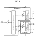
- FIG. 3 A block diagram of the configuration of a reception side of an optical wavelength division multiplexing and transmission apparatus is shown in Fig. 3.
- 40 indicates a master rack.
- the master rack 40 accommodates an amplifier 41, an amplifier 43, a synthetic optical wavelength demultiplexer 42 and an optical wavelength demultiplexer (or first optical wavelength demultiplexer) 44.
- 50 indicates a slave rack.
- the slave rack 50 accommodates an amplifier 51 and an optical wavelength demultiplexer (or second optical wavelength demultiplexer) 52.
- the slave rack 50 can be coupled to the master rack 40 at any time.
- an optical signal of the master rack 40 is couple to the slave rack 50 through an optical connector 45.
- the master rack 40 or the slave rack 50 has an interface to perform this signal coupling. Next, an operation will be described below.
- a synthetic multiplexed signal which is transmitted from an opposite end transmitter having the configuration shown in Fig. 2 through the optical transmission line 113, is amplified in the amplifier 41 and is input to the synthetic optical wavelength demultiplexer 42.
- a plurality of optical wavelength signals ⁇ 1, ⁇ 2, ⁇ and ⁇ n of wavelengths different from each other and having an optical wavelength distribution are multiplexed with each other to form a multiplexed signal
- a plurality of optical wavelength signals ⁇ n+1, ⁇ n+2, ⁇ and ⁇ m having wavelengths different from each other and having an optical wavelength distribution different from that of the group of the optical wavelength signals ⁇ 1, ⁇ 2, ⁇ and ⁇ n are multiplexed with each other to form another multiplexed signal
- the synthetic multiplexed signal is formed by multiplexing the multiplexed signals with each other.
- a multiplexed signal (or first multiplexed signal) formed by the demultiplexing of the synthetic optical wavelength demultiplexer 42 is amplified in the amplifier 43 and is input to the optical wavelength demultiplexer (or first optical wavelength demultiplexer) 44. Thereafter, the multiplexed signal is demultiplexed to the optical wavelength signals ⁇ 1, ⁇ 2, ⁇ and ⁇ n of one group in the optical wavelength demultiplexer 44, and the group of the optical wavelength signals ⁇ 1, ⁇ 2, ⁇ and ⁇ n is sent to a circuit of a latter stage.
- another multiplexed signal (or second multiplexed signal) formed by the demultiplexing of the synthetic optical wavelength demultiplexer 42 is fed to the amplifier 51 through the optical connector 45 and is amplified. Thereafter, the multiplexed signal is input to the optical wavelength demultiplexer (or second optical wavelength demultiplexer) 52 and is demultiplexted to the optical wavelength signals ⁇ n+1, ⁇ n+2, ⁇ and ⁇ m of one group.
- the receiver end of the optical wavelength division multiplexing and transmission apparatus has the configuration in which the slave rack 50 can be additionally installed. Accordingly, the slave rack 50 can be easily and additionally installed in the optical wavelength division multiplexing and transmission apparatus without stopping the operation of the system installed for the early operation, and the optical wavelength division multiplexing and transmission apparatus can be widely used for various purposes.
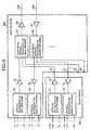
- FIG. 4 A block diagram of the configuration of an optical wavelength division multiplexing and transmission apparatus, in which circuits of a transmission function and circuits of a reception function are integrally formed, is shown in Fig. 4.
- circuits of a transmission function which are the same as those shown in Fig. 2
- circuits of a reception function which are the same as those shown in Fig. 3
- circuits of a reception function which are the same as those shown in Fig. 3
- a master rack 200 indicates a receiving and transmitting system installed for the early operation.
- a slave rack 300 is coupled to the master rack 200 in cases where the number of optical wavelength signals processed is increased, and a transmitting and receiving function is expanded by the slave rack 300.
- the optical wavelength signals denoting the input of the optical wavelength multiplexer 21 are indicated by the same reference numerals ⁇ 1, ⁇ 2, ⁇ and ⁇ n as those denoting the output of optical wavelength demultiplexer 44.
- a plurality of optical wavelength signals denoting the input are indicated by the same reference numerals ⁇ n+1, ⁇ n+2, ⁇ and ⁇ m as those denoting the output.
- a plurality of optical wavelength signals ⁇ 1, ⁇ 2, ⁇ and ⁇ n are multiplexed in the optical wavelength multiplexer 21, and a multiplexed signal (or first multiplexed signal) is output from the optical wavelength multiplexer 21.
- This multiplexed signal is amplified in the amplifier 22 and is fed to the synthetic optical wavelength multiplexer 23.
- the multiplexed signal is multiplexed with the same type of multiplexed signal (or second multiplexed signal) as that of the multiplexed signal to obtain a synthetic multiplexed signal (or first synthetic multiplexed signal), and the synthetic multiplexed signal is output to the optical transmission line 120 through the amplifier 24.
- the synthetic optical wavelength demultiplexer 42 After a synthetic multiplexed signal (or second synthetic multiplexed signal), which is transmitted from another optical wavelength division multiplexing and transmission apparatus of the opposite end through the optical transmission line 140, is amplified in the amplifier 41, the synthetic multiplexed signal is input and demultiplexted to a plurality of multiplexed signals.
- One multiplexed signal (or third multiplexed signal) demultiplexted in the synthetic optical wavelength demultiplexer 42 is amplified in the amplifier 43. Thereafter, the multiplexed signal is input to the optical wavelength demultiplexer (or first optical wavelength demultiplexer) 44 and is demultiplexed to the optical wavelength signals ⁇ 1, ⁇ 2, ⁇ and ⁇ n of one group.
- a plurality of optical wavelength signals ⁇ n+1, ⁇ n+2, ⁇ and ⁇ m having a wavelength distribution different from that of the optical wavelength signals ⁇ 1, ⁇ 2, ⁇ and ⁇ n are multiplexed with each other in the optical wavelength multiplexer (or second optical wavelength multiplexer) 31, and a multiplexed signal (or second multiplexed signal) is fed to the synthetic optical wavelength multiplexer 23 of the master rack 200 through the amplifier 32.
- another multiplexed signal which is formed by demultiplexing the synthetic multiplexed signal transmitted through the optical transmission line 140 in the synthetic optical wavelength demultiplexer 42, is demultiplexed to the optical wavelength signals ⁇ n+1, ⁇ n+2, ⁇ and ⁇ m in the optical wavelength demultiplexer (or second optical wavelength demultiplexer) 52, and the optical wavelength signals ⁇ n+1, ⁇ n+2, ⁇ and ⁇ m is output.
- the slave rack 300 when the slave rack 300 is additionally installed in the optical wavelength division multiplexing and transmission apparatus, the slave rack 300 can be easily and additionally installed without stopping the operation of the system installed for the early operation. Also, because each of the master rack 200 and the slave rack 300 accommodates circuits of an optical multiplexing function and circuits of an optical demultiplexing function, the circuits of the optical multiplexing function and the circuits of the optical demultiplexing function in the slave rack 300 can be simultaneously and additionally installed in the optical wavelength division multiplexing and transmission apparatus, and workability can be further improved in the optical wavelength division multiplexing and transmission apparatus.
- FIG. 5 A block diagram of the configuration of an optical wavelength division multiplexing and transmission apparatus, in which an additional circuit is installed on the transmitter end, is shown in Fig. 5.
- the additional circuit is formed of a plurality of noise cut filters 201, 202 and 203 installed on the input side of the synthetic optical wavelength multiplexer 23.
- the group of optical wavelength signals ⁇ 1, ⁇ 2, ⁇ and ⁇ n multiplexed in the first optical wavelength multiplexer 21 is multiplexed in the synthetic optical wavelength multiplexer 23 with the group of optical wavelength signals ⁇ n+1, ⁇ n+2, ⁇ and ⁇ m multiplexed in the optical wavelength multiplexer 31, noise components included in the groups of optical wavelength signals are added to each other so as to increase a noise level, and an S/N ratio of the synthetic multiplexed signal is lowered.
- a band of a prescribed band width is set for each group of optical wavelength signals, and unnecessary signal components existing outside the band are cut away in each of the noise cut filters 201, 202 and 203.
- the noise cut filters 201, 202 and 203 are installed in the master rack 20. However, it is applicable that the noise cut filters 202 and 203 be installed in the slave racks 30 respectively. Also, the installation of the noise cut filters 201, 202 and 203 can be adapted for the optical wavelength division multiplexing and transmission apparatus of Fig. 4 functioning as a transceiver.
- the noise cut filters 201, 202 and 203 are inserted into the optical wavelength division multiplexing and transmission apparatus so as to transmit only an effective wavelength portion of each group of optical wavelength signals through the corresponding noise cut filter. Therefore, communication quality of the optical wavelength division multiplexing and transmission apparatus can be improved.
- FIG. 6 A block diagram of the configuration of an optical wavelength division multiplexing and transmission apparatus, in which a plurality of dispersion compensation fibers 205, 206 and 207 are installed on the receiver end as an additional circuit, is shown in Fig. 6.
- the dispersion compensation fibers 205, 206 and 207 are installed on the input side of the synthetic optical wavelength multiplexer 23 of the master rack 20.
- each optical wavelength signal is transmitted through an optical fiber of a transmission line, a wavelength distortion occurs in the optical wavelength signal due to the dispersion of the optical wavelength signal peculiar to the optical fiber. Therefore, the transmission quality of the optical wavelength signal is lowered.
- each multiplexed signal is fed to the synthetic optical wavelength multiplexer 23 through the corresponding dispersion compensation fiber 205, 206 or 207 so as to compensate for the dispersion of the multiplexed signal expected to be accumulated in an optical fiber of a transmission line.
- Each of the dispersion compensation fibers 205, 206 and 207 has a function of preventing the dispersion of the multiplexed signal occurring in an optical fiber of a transmission line, and the distortion of each optical wavelength signal can be prevented.
- the dispersion compensation fibers 206 and 207 be installed in the slave racks 30 respectively. Also, the installation of the dispersion compensation fibers 205, 206 and 207 can be adapted for the optical wavelength division multiplexing and transmission apparatus of Fig. 4 functioning as a transceiver.
- the dispersion compensation fibers 205, 206 and 207 are inserted into the optical wavelength division multiplexing and transmission apparatus, and the communication quality of the WDM transmission system can be improved.
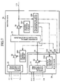
- FIG. 7 A block diagram of the configuration of an optical wavelength division multiplexing and transmission apparatus, in which a wavelength level monitoring device 208 and a plurality of output control circuits 209, 210 and 211 are installed on the receiver end as an additional circuit, is shown in Fig. 7.
- the wavelength level monitoring device 208 has a function of monitoring levels of the optical wavelength signals of the synthetic multiplexed signal which is output from the amplifier 24.
- a monitored level of each optical wavelength signal detected in the wavelength level monitoring device 208 is fed back to the corresponding amplifier 22 or 32 through the corresponding output control circuit 209 or 210 installed in the master rack 20 or the slave rack 30, and the output control circuits 209 and 210 control the amplifiers 22 and 32 respectively to equalize levels of the optical wavelength signals of the multiplexed signals (or first and second multiplexed signals) with each other.
- the output control circuit 211 controls the amplifier 24 to set a level of the synthetic multiplexed signal output from the amplifier 24 of the final stage to a predetermined value.
- level differences among the multiplexed signals of the groups of optical wavelength signals can be corrected before the signal transmission, and the transmission qualities of the multiplexed signals can be equally maintained.
- an optical wavelength division multiplexing and transmission apparatus has the configuration in which a plurality of slave racks coupling to a master rack can be additionally installed one after another with the master rack. Therefore, in cases where it is desired to expand a function of a transmitter and a function of a receiver due to the increase of a quality of information to be transmitted, the additional installation of the slave rack can be performed without exerting influence on a communication means installed in advance and currently used. Accordingly, it can be expected that the optical wavelength division multiplexing and transmission apparatus is adapted for the optical communication service which is more and more increased in the future.
Landscapes
- Engineering & Computer Science (AREA)
- Computer Networks & Wireless Communication (AREA)
- Signal Processing (AREA)
- Physics & Mathematics (AREA)
- Electromagnetism (AREA)
- Optical Communication System (AREA)
Abstract
Description
Claims (8)
- An optical wavelength division multiplexing and transmission apparatus, comprising a master rack and at least a slave rack possible to be combined with and coupled to the master rack, wherein
a structure body of the master rack accommodates a first optical wavelength multiplexer in which a plurality of prescribed optical wavelength signals of a group are multiplexed with each other and a first multiplexed signal is output, and a synthetic optical wavelength multiplexer in which the first multiplexed signal output from the first optical wavelength multiplexer and a second multiplexed signal are multiplexed with each other and a synthetic multiplexed signal is output, and
a structure body of the slave rack accommodates a second optical wavelength multiplexer in which a plurality of optical wavelength signals of a group having a wavelength distribution different from that of the group of prescribed optical wavelength signals multiplexed by the first optical wavelength multiplexer are multiplexed with each other and are output as the second multiplexed signal. - An optical wavelength division multiplexing and transmission apparatus, comprising a master rack and at least a slave rack possible to be combined with and coupled to the master rack, wherein
a structure body of the master rack accommodates a synthetic optical wavelength demultiplexer in which a synthetic multiplexed signal formed by multiplexing a plurality of multiplexed signals, which are respectively formed of a plurality of groups of optical wavelength signals having a plurality of optical wavelength distributions different from each other, with each other is received, the synthetic multiplexed signal is demultiplexed to both a first multiplexed signal and a second multiplexed signal and both the first multiplexed signal and the second multiplexed signal are output, and a first optical wavelength demultiplexer in which the first multiplexed signal output by the synthetic optical wavelength demultiplexer is demultiplexed to a plurality of optical wavelength signals of one group and the group of optical wavelength signals is output, and
a structure body of the slave rack accommodates a second optical wavelength demultiplexer in which the second multiplexed signal output by the synthetic optical wavelength demultiplexer is demultiplexed to a plurality of optical wavelength signals of another group and the group of optical wavelength signals is output. - An optical wavelength division multiplexing and transmission apparatus, comprising a master rack and at least a slave rack possible to be combined with and coupled to the master rack, wherein
a structure body of the master rack accommodates a first optical wavelength multiplexer in which a plurality of prescribed optical wavelength signals of a group are multiplexed with each other and a first multiplexed signal is output, a synthetic optical wavelength multiplexer in which the first multiplexed signal output from the first optical wavelength multiplexer and a second multiplexed signal are multiplexed with each other and a first synthetic multiplexed signal is output, a synthetic optical wavelength demultiplexer in which a second synthetic optical wavelength transmitted from another optical wavelength division multiplexing and transmission apparatus of an opposite end through an optical transmission line is demultiplexed to both a third multiplexed signal and a fourth multiplexed signal and both the third multiplexed signal and the fourth multiplexed signal are output, and a first optical wavelength demultiplexer in which the third multiplexed signal output from synthetic optical wavelength demultiplexer is demultiplexed to a plurality of optical wavelength signals of a group and the group of optical wavelength signals is output, and
a structure body of the slave rack accommodates a second optical wavelength multiplexer in which a plurality of optical wavelength signals of a group having a wavelength distribution different from that of the group of prescribed optical wavelength signals multiplexed by the first optical wavelength multiplexer are multiplexed with each other and are output as the second multiplexed signal, and a second optical wavelength demultiplexer in which the fourth multiplexed signal output by the synthetic optical wavelength demultiplexer is demultiplexed to a plurality of optical wavelength signals of another group and the group of optical wavelength signals is output. - An optical wavelength division multiplexing and transmission apparatus according to claim 1, further comprising a plurality of noise cut filters corresponding to the first multiplexed signal and the second multiplexed signal respectively on an input side of the synthetic optical wavelength multiplexer on which the first multiplexed signal and the second multiplexed signal are input.
- An optical wavelength division multiplexing and transmission apparatus according to claim 3, further comprising a plurality of noise cut filters corresponding to the first multiplexed signal and the second multiplexed signal respectively on an input side of the synthetic optical wavelength multiplexer on which the first multiplexed signal and the second multiplexed signal are input.
- An optical wavelength division multiplexing and transmission apparatus according to claim 1, further comprising a plurality of dispersion compensation fibers corresponding to the first multiplexed signal and the second multiplexed signal respectively on an input side of the synthetic optical wavelength multiplexer on which the first multiplexed signal and the second multiplexed signal are input.
- An optical wavelength division multiplexing and transmission apparatus according to claim 3, further comprising a plurality of dispersion compensation fibers corresponding to the first multiplexed signal and the second multiplexed signal respectively on an input side of the synthetic optical wavelength multiplexer on which the first multiplexed signal and the second multiplexed signal are input.
- An optical wavelength division multiplexing and transmission apparatus according to claim 1, further comprising an amplifier of the master rack for the first multiplexed signal, an amplifier of the master rack for the synthetic multiplexed signal, a wavelength level monitoring device of the master rack for monitoring an output of the amplifier for the synthetic multiplexed signal, an amplifier of the slave rack for the second multiplexed signal, and a plurality of output control circuits for selectively controlling a plurality of levels of signals output from the amplifier for the first multiplexed signal, the amplifier for the second multiplexed signal and the amplifier for the synthetic multiplexed signal respectively in response to a detection output of the wavelength level monitoring device in which a plurality of levels of the optical wavelength signals of the first multiplexed signal, the second multiplexed signal and the synthetic multiplexed signal are monitored.
Applications Claiming Priority (1)
| Application Number | Priority Date | Filing Date | Title |
|---|---|---|---|
| PCT/JP2000/005151 WO2002011337A1 (en) | 2000-07-31 | 2000-07-31 | Optical wavelength division multiplexing device |
Publications (2)
| Publication Number | Publication Date |
|---|---|
| EP1220483A1 true EP1220483A1 (en) | 2002-07-03 |
| EP1220483A4 EP1220483A4 (en) | 2005-09-07 |
Family
ID=11736317
Family Applications (1)
| Application Number | Title | Priority Date | Filing Date |
|---|---|---|---|
| EP00948348A Withdrawn EP1220483A4 (en) | 2000-07-31 | 2000-07-31 | DEVICE FOR OPTICAL WAVELENGTH MULTIPLEX |
Country Status (3)
| Country | Link |
|---|---|
| US (1) | US7236703B1 (en) |
| EP (1) | EP1220483A4 (en) |
| WO (1) | WO2002011337A1 (en) |
Families Citing this family (3)
| Publication number | Priority date | Publication date | Assignee | Title |
|---|---|---|---|---|
| JP2008227556A (en) * | 2005-05-17 | 2008-09-25 | Nec Corp | Wavelength multiplexing optical transmission apparatus and wavelength multiplexing optical transmission method |
| JP4882539B2 (en) * | 2006-06-21 | 2012-02-22 | 日本電気株式会社 | Mobile communication system, baseband server, and signal relay method used therefor |
| JP5266796B2 (en) | 2008-03-03 | 2013-08-21 | 日本電気株式会社 | Optical wavelength division multiplexer, optical wavelength division multiplexer, optical wavelength division multiplexer, and optical bandpass filter control method |
Family Cites Families (32)
| Publication number | Priority date | Publication date | Assignee | Title |
|---|---|---|---|---|
| DE3037712A1 (en) * | 1980-10-06 | 1982-05-13 | Siemens AG, 1000 Berlin und 8000 München | OPTICAL WAVELENGTH MULTIPLEX SYSTEM |
| JPH01282931A (en) | 1988-05-09 | 1989-11-14 | Nippon Telegr & Teleph Corp <Ntt> | Optical wavelength multiplex and optical code multiplex transmitter |
| JPH05327662A (en) * | 1992-05-25 | 1993-12-10 | Matsushita Electric Ind Co Ltd | WDM light source |
| CA2139957C (en) * | 1994-02-18 | 1999-02-09 | Andrew R. Chraplyvy | Multi-channel optical fiber communication system |
| JPH0846595A (en) * | 1994-07-28 | 1996-02-16 | Hitachi Ltd | Optical transmission device |
| JPH08102749A (en) * | 1994-08-02 | 1996-04-16 | Fujitsu Ltd | ATM switch and path replacement method using ATM switch |
| JPH08278523A (en) * | 1995-04-05 | 1996-10-22 | Hitachi Ltd | Optical amplifier |
| JP3720112B2 (en) * | 1996-03-18 | 2005-11-24 | 富士通株式会社 | System and optical power control apparatus to which wavelength division multiplexing is applied |
| JP4405598B2 (en) | 1996-07-09 | 2010-01-27 | 富士通株式会社 | Signal light output device and optical transmission system having signal light output device |
| JPH10173264A (en) * | 1996-12-09 | 1998-06-26 | Kokusai Denshin Denwa Co Ltd <Kdd> | Gain equalizer |
| WO1998036514A1 (en) * | 1997-02-14 | 1998-08-20 | Nippon Telegraph And Telephone Corporation | Wavelength division multiplexing optical transmission system |
| JPH10322313A (en) * | 1997-05-16 | 1998-12-04 | Nec Corp | Wavelength multiplexing transmitter |
| JPH1155181A (en) * | 1997-07-31 | 1999-02-26 | Kokusai Denshin Denwa Co Ltd <Kdd> | WDM optical transmission system |
| US6122096A (en) * | 1997-08-29 | 2000-09-19 | Lucent Technologies Inc. | Expandable wavelength-selective and loss-less optical add/drop system |
| US6041152A (en) * | 1997-09-02 | 2000-03-21 | Amphenol Corporation | Multi-channel fiber optic communications system and multiplexer/demultiplexer arrangement therefor |
| JPH11103286A (en) * | 1997-09-25 | 1999-04-13 | Nec Corp | Wavelength multiplexed light transmitting device |
| JP3425861B2 (en) | 1998-02-20 | 2003-07-14 | 富士通株式会社 | Optical switch |
| CN1246005A (en) * | 1998-03-27 | 2000-03-01 | Afc技术公司 | Compact wavelength division multiplex optic transmission system with double bandwidth |
| US6782203B2 (en) * | 1998-08-31 | 2004-08-24 | Lucent Technologies Inc. | Scalable optical demultiplexing arrangement for wide band dense wavelength division multiplexed systems |
| US6614567B1 (en) * | 1998-08-31 | 2003-09-02 | Lucent Technologies Inc. | Apparatus and method for upgrading the capacity of wavelength division multiplexed optical networks |
| JP2000092001A (en) | 1998-09-09 | 2000-03-31 | Nippon Telegr & Teleph Corp <Ntt> | Optical transmitter |
| JP2000183815A (en) | 1998-12-11 | 2000-06-30 | Nippon Telegr & Teleph Corp <Ntt> | Optical transmission system |
| US6721508B1 (en) * | 1998-12-14 | 2004-04-13 | Tellabs Operations Inc. | Optical line terminal arrangement, apparatus and methods |
| US6567196B1 (en) * | 1999-03-22 | 2003-05-20 | Ciena Corporation | Dense WDM optical multiplexer and demultiplexer |
| US6323994B1 (en) * | 1999-04-12 | 2001-11-27 | Nortel Networks Limited | WDM system equalization with EDFA optical amplifiers |
| JP2001094510A (en) * | 1999-09-24 | 2001-04-06 | Ddi Corp | Optical transmission system, optical transmission line, and optical transmission device |
| US6307668B1 (en) * | 1999-10-04 | 2001-10-23 | Optigain, Inc. | Ultra-wide bandwidth fiber based optical amplifier |
| US6690886B1 (en) * | 1999-12-22 | 2004-02-10 | Nortel Networks Limited | Suppression of four-wave mixing in ultra dense WDM optical communication systems through optical fibre dispersion map design |
| US6731877B1 (en) * | 2000-03-03 | 2004-05-04 | Qtera Corporation | High capacity ultra-long haul dispersion and nonlinearity managed lightwave communication systems |
| JP2002158636A (en) * | 2000-03-29 | 2002-05-31 | Hitachi Ltd | Optical transmission device and its monitoring system |
| JP4234927B2 (en) * | 2000-04-14 | 2009-03-04 | 富士通株式会社 | Optical wavelength division multiplexing transmission system, optical output control method, and optical wavelength division multiplexing transmission apparatus |
| US6708002B1 (en) * | 2002-01-16 | 2004-03-16 | Dorsal Networks, Inc. | Modular multiplexing/demultiplexing units in optical transmission systems |
-
2000
- 2000-07-31 EP EP00948348A patent/EP1220483A4/en not_active Withdrawn
- 2000-07-31 US US10/088,503 patent/US7236703B1/en not_active Expired - Lifetime
- 2000-07-31 WO PCT/JP2000/005151 patent/WO2002011337A1/en not_active Ceased
Also Published As
| Publication number | Publication date |
|---|---|
| US7236703B1 (en) | 2007-06-26 |
| WO2002011337A1 (en) | 2002-02-07 |
| EP1220483A4 (en) | 2005-09-07 |
Similar Documents
| Publication | Publication Date | Title |
|---|---|---|
| EP1583269A2 (en) | Coarse wavelength division multiplexing optical transmission system, and coarse wavelength division multiplexing optical transmission method | |
| US20110311216A1 (en) | Optical signal level adjustment system, information analysis/control signal generation apparatus in the same system, and information analysis/control signal generation method | |
| US6411407B1 (en) | Method for providing a bidirectional optical supervisory channel | |
| US8195052B2 (en) | Optical wavelength multiplexing system, optical wavelength multiplexing method, and computer product | |
| US6577652B1 (en) | Optical add-drop multiplexer of WDM optical signals | |
| JP4294452B2 (en) | Optical device for bidirectional optical communication | |
| EP1139588A2 (en) | Optical transmission equipment and supervisory system thereof | |
| US20040197100A1 (en) | Optical transmission system and optical coupler/branching filter | |
| JP5887698B2 (en) | Optical coupling / branching device and optical coupling / branching method | |
| JP4089504B2 (en) | Single-core bidirectional optical transmission system, single-core bidirectional optical amplifier and method | |
| AU757003B2 (en) | WDM transmission repeater, WDM transmission system and WDM transmission method | |
| EP0844752A2 (en) | Automatic dispersion compensating optical transmission system | |
| JP4826451B2 (en) | Optical transmission device with optical amplifier | |
| US7236703B1 (en) | Optical wavelength division multiplexing device | |
| US7130542B2 (en) | Modular multiplexing/demultiplexing units in optical transmission systems | |
| US20230104128A1 (en) | Submarine optical communication system and communication method | |
| JP4376014B2 (en) | Optical transmission equipment | |
| JP2002185407A (en) | OADM node and wavelength multiplexing network using the same | |
| EP0994595A2 (en) | Wavelength multiplexer/demultiplexer and optical transmission apparatus | |
| JP3039430B2 (en) | Optical add / drop circuit and optical transmission method | |
| KR100434454B1 (en) | Daisy chain wavelength division multiplexing device and daisy chain wavelength division multiplexing system and transmission network utilizing the device | |
| EP1096713A2 (en) | Optical add/drop multiplexer | |
| JP2008294818A (en) | Wavelength multiplexing transmission system and optical transmission apparatus | |
| JP2001007767A (en) | Optical communication system, optical receiver, and optical communication method | |
| JP2000068931A (en) | Optical wavelength add / drop device |
Legal Events
| Date | Code | Title | Description |
|---|---|---|---|
| PUAI | Public reference made under article 153(3) epc to a published international application that has entered the european phase |
Free format text: ORIGINAL CODE: 0009012 |
|
| AK | Designated contracting states |
Kind code of ref document: A1 Designated state(s): AT BE CH CY DE DK ES FI FR GB GR IE IT LI LU MC NL PT SE |
|
| AX | Request for extension of the european patent |
Free format text: AL;LT;LV;MK;RO;SI |
|
| 17P | Request for examination filed |
Effective date: 20020328 |
|
| RBV | Designated contracting states (corrected) |
Designated state(s): DE FR GB IT |
|
| A4 | Supplementary search report drawn up and despatched |
Effective date: 20050725 |
|
| RIC1 | Information provided on ipc code assigned before grant |
Ipc: 7G 02B 6/12 B Ipc: 7H 04J 14/02 A Ipc: 7H 04B 10/18 B Ipc: 7H 04B 10/155 B |
|
| RAP1 | Party data changed (applicant data changed or rights of an application transferred) |
Owner name: KDD SUBMARINE CABLE SYSTEMS INC. Owner name: MITSUBISHI DENKI KABUSHIKI KAISHA |
|
| 17Q | First examination report despatched |
Effective date: 20051103 |
|
| GRAP | Despatch of communication of intention to grant a patent |
Free format text: ORIGINAL CODE: EPIDOSNIGR1 |
|
| STAA | Information on the status of an ep patent application or granted ep patent |
Free format text: STATUS: THE APPLICATION HAS BEEN WITHDRAWN |
|
| RIN1 | Information on inventor provided before grant (corrected) |
Inventor name: SHIMIZU, KATSUHIRO,MITSUBISHI DENKI K.K. Inventor name: YAMANAKA, SHIGEO,MITSUBISHI DENKI K.K Inventor name: GOTO, KOJI,KDD SUBMARINE CABLE SYSTEMS INC. Inventor name: SHIBANO, EIICHI,KDD SUBMARINE CABLE SYS. INC. Inventor name: NAKAGAWA, SHINICHI,KDD SUBMARINE CABLE SYS. INC. Inventor name: YASUDA, TADAMI,KDD SUBMARINE CABLE SYS. INC. Inventor name: MIZUOCHI, TAKASHI,MITSUBISHI DENKI K.K. |
|
| 18W | Application withdrawn |
Effective date: 20070227 |