BACKGROUND OF THE INVENTION
1. Field of the Invention
The present invention relates to a display apparatus.
2. Description of Related Art
There has been proposed a display element that includes a light guide
plate for transmitting light therethrough, and a driving portion arranged opposite to
one plate surface of the light guide plate, wherein the driving portion is provided
with actuator portions, the number of which corresponds to that of a number of pixels.
The display element is operated so as to display a video image on the light guide
plate according to an inputted image signal, by introducing light into the light guide
plate and controlling displacement operations of the actuator portions in contact and
separation directions with respect to the light guide plate according to properties of
the image signal and controlling leakage light in a predetermined region of the light
guide plate (see, U.S. Patent No. 5,636,072 or JP-A-11-194723). The display
element of such structure may be referred to as "display element related to the
invention", hereinafter.
The display element related to the invention differs from liquid crystal
display or plasma display in that it does not basically require a seal structure. Thus,
it is possible to realize a display element having a divided panel structure that is
highly suitable for upsizing and reduction in thickness of the panel without particular
difficulties. Also, since the display element is of direct viewing type, it is readily
possible to achieve high contrast and satisfactory resistance to color fading even
when irradiated by external light, besides that a more excellent view angle can be
obtained in comparison with CRT.
SUMMARY OF THE INVENTION
It is a primary object of the present invention to provide a novel display
apparatus actively utilizing advantageous functional characteristics of the display
element related to the present invention described above.
According to a first aspect of the present invention, there is provided a
display apparatus which comprises plural display units, wherein each of the display
units comprises a light guide plate for transmitting light therethrough, and a display
element which is provided opposite to one plate surface of said light guide plate, said
display element comprising a driving portion provided with actuator portions of a
number corresponding to that of a number of pixels, said display element causing the
light guide plate to display a video image according to an inputted image signal, by
introducing light into the light guide plate and controlling displacement operations in
contact and separation directions of the actuator portion with respect to the light
guide plate according to properties of the image signal, and thereby controlling
leakage light in a predetermined region of the light guide plate, and wherein the
plural display units are joined and arranged so as to form a predetermined angle
relative to each other. As used herein, the "joining" is to be understood as meaning
that the display units are maintained in a predetermined angular position relative to
each other, and is not necessarily limited to a physical contact between the display
units. The "predetermined" angle is typically any non-zero angle, e.g. 10° or more.
In this case, it is preferred that the plural display units are joined so that
the light guide plates of the display units, which are arranged adjacent to each other,
form video image display surfaces that appear as if they are in one plane.
The joint angle of the display units may be set to an angle at which a
joint portion of the display units protrudes away from a viewer. Alternatively, the
joint angle of the display units may be set to an angle at which a joint portion of the
display units protrudes toward a viewer.
In the display apparatus of the structure described above, a reflector is
preferably arranged along a side of the light guide plate in a joint portion of the
display units. In this case, a light source may be arranged between the side of the
light guide plate and the reflector. Also, a reflector may be arranged along the side
of the light guide plate, which is remote from the joint portion of the display units.
Also in this case, a light source may be arranged between the side of the light guide
plate and the reflector. Furthermore, a reflector may be arranged along the top
and/or bottom of the light guide plate. Also in this case, a light source may be
arranged between the top or bottom of the light guide plate and the reflector provided
along the top or bottom.
In the display apparatus of the structure described above, a columnar
transparent body may be arranged along the side of the light guide plate in a joint
portion of the display units without being in contact with that side. In this case, a
light absorption layer is preferably provided on the upper surface and the lower
surface of the transparent body.
In the display apparatus of the structure described above, the light guide
plate may be formed to have a wedge-like sectional shape with its thickness
decreasing gradually toward the joint portion of the display units. In this case, a
reflector having the required minimum area is advantageously provided on the side
of the light guide plate in the joint portion of the display units. Then, a light source
and a reflector are preferably arranged along the side of the light guide plate, which
is remote from the joint portion of the display units, or along the top and/or bottom of
the light guide plate.
According to a second aspect of the present invention, there is provided a
display apparatus which comprises a display unit, wherein the display unit comprises
a light guide plate for transmitting light therethrough, and a display element which is
provided opposite to one plate surface of said light guide plate, said display element
comprising a driving portion provided with actuator portions of a number
corresponding to that of a number of pixels, said display element causing the light
guide plate to display a video image according to an inputted image signal, by
introducing light into the light guide plate and controlling displacement operations in
contact and separation directions of the actuator portion with respect to the light
guide plate according to properties of the image signal, and thereby controlling
leakage light in a predetermined region of the light guide plate, and wherein the light
guide plate is formed as a curved surface having a predetermined curvature.
In this case, it is preferred that a light source and/or a reflector are
arranged along the side, top and/or bottom of the light guide plate.
It is preferred that plurality of the display apparatuses according to the
present invention are combined with each other to form a structural body having a
desired three-dimensional shape. In this case, it is possible to combine the light
guide plates of the structural body so as to form a video image display plane on an
inner surface of a planetarium.
According to a third aspect of the present invention, there is provided a
display apparatus which comprises a display unit, wherein the display unit comprises
a light guide plate for transmitting light therethrough, and a display element which is
provided opposite to one plate surface of said light guide plate, said display element
comprising a driving portion provided with actuator portions of a number
corresponding to that of a number of pixels, said display element causing the light
guide plate to display a video image according to an inputted image signal, by
introducing light into the light guide plate and controlling displacement operations in
contact and separation directions of the actuator portion with respect to the light
guide plate according to properties of the image signal, and thereby controlling
leakage light in a predetermined region of the light guide plate, and wherein the
display unit is arranged to extend with a continuous band shape on a wall of a
passage along which people traffic.
In this case, it is preferred that a sensor for detecting traffic of people is
connected to the display apparatus, and the display apparatus is operated to display a
video image on the light guide plate, when the sensor detects traffic of people.
According to a fourth aspect of the present invention, there is provided a
display apparatus which comprises a display unit, wherein the display unit comprises
a light guide plate for transmitting light therethrough. and a display element which is
provided opposite to one plate surface of said light guide plate, said display element
comprising a driving portion provided with actuator portions of a number
corresponding to that of a number of pixels, said display element causing the light
guide plate to display a video image according to an inputted image signal, by
introducing light into the light guide plate and controlling displacement operations in
contact and separation directions of the actuator portion with respect to the light
guide plate according to properties of the image signal, and thereby controlling
leakage light in a predetermined region of the light guide plate, and wherein the light
guide plate forms a video image display surface in a cinema complex.
According to a fifth aspect of the present invention, there is provided a
display apparatus which comprises plural display units, wherein each of the display
unit comprises a light guide plate for transmitting light therethrough, and a display
element which is provided opposite to one plate surface of said light guide plate, said
display element comprising a driving portion provided with actuator portions of a
number corresponding to that of a number of pixels, said display element causing the
light guide plate to display a video image according to an inputted image signal, by
introducing light into the light guide plate and controlling displacement operations in
contact and separation directions of the actuator portion with respect to the light
guide plate according to properties of the image signal, and thereby controlling
leakage light in a predetermined region of the light guide plate, and wherein the
display element and the light guide plate have desired shapes, respectively, and the
display apparatus has a desired shape by arranging the display element in close
contact with a back side of the light guide plate with a desired configuration.
According to a sixth aspect of the present invention, there is provided a
display apparatus which comprises plural display units, wherein each of the display
unit comprises a light guide plate for transmitting light therethrough, and a display
element which is provided opposite to one plate surface of said light guide plate, said
display element comprising a driving portion provided with actuator portions of a
number corresponding to that of a number of pixels, said display element causing the
light guide plate to display a video image according to an inputted image signal, by
introducing light into the light guide plate and controlling displacement operations in
contact and separation directions of the actuator portion with respect to the light
guide plate according to properties of the image signal, and thereby controlling
leakage light in a predetermined region of the light guide plate, and wherein the
display element is arranged in close contact with a desired position on a back side of
the light guide plate, and at least one of a blank region, a light emission body, a
scattering body and a light absorbing body is arranged at other desired position or
positions on the back side of the light guide plate.
According to a seventh aspect of the present invention, there is provided
a display apparatus which comprises plural display units, wherein each of the display
unit comprises a light guide plate for transmitting light therethrough, and a display
element which is provided opposite to one plate surface of said light guide plate, said
display element comprising a driving portion provided with actuator portions of a
number corresponding to that of a number of pixels, said display element causing the
light guide plate to display a video image according to an inputted image signal, by
introducing light into the light guide plate and controlling displacement operations in
contact and separation directions of the actuator portion with respect to the light
guide plate according to properties of the image signal, and thereby controlling
leakage light in a predetermined region of the light guide plate, and wherein said
display elements include display elements having different color and/or different
pixel area and/or different pixel pitch, and said display elements are arranged on a
backside of the same light guide plate.
According to an eighth aspect of the present invention, there is provided
a display apparatus which comprises plural display units, wherein each of the display
unit comprises a light guide plate for transmitting light therethrough, and a display
element which is provided opposite to one plate surface of said light guide plate, said
display element comprising a driving portion provided with actuator portions of a
number corresponding to that of a number of pixels, said display element causing the
light guide plate to display a video image according to an inputted image signal, by
introducing light into the light guide plate and controlling displacement operations in
contact and separation directions of the actuator portion with respect to the light
guide plate according to properties of the image signal, and thereby controlling
leakage light in a predetermined region of the light guide plate, and wherein said
display elements are arranged on backsides of the light guide plates, and the light
guide plates are so arranged as to display portions of a video image from the same
image signal source, respectively.
BRIEF DESCRIPTION OF THE DRAWINGS
The present invention will be described below in further detail with
reference to preferred embodiments that are illustrated in the accompanying
drawings.
DETAILED DESCRIPTION OF PREFERRED EMBODIMENTS
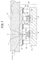
Referring now to Fig. 1, there is shown a display element that can be
suitably used in the display apparatus according to the present invention. The
display element is designated as a whole by reference numeral 10, and includes a
light guide plate 11 for introducing light, for example, from a side surface and a
driving portion 13 which is arranged opposite to one plate surface of the light guide
plate 11 and provided with actuator portions 12 of the number corresponding to that
of a number of pixels. Then, by controlling displacement operations of the actuator
portions 12 in contact and separation directions with respect to the light guide plate
11 according to properties of an image signal inputted to the apparatus and thereby
controlling leakage light in a predetermined region of the light guide plate 11, a
video image according to the image signal is displayed on the light guide plate 11.
As disclosed in U.S. Patent No, 5,636,072 or JP-A-11-194723 cited
above, the actuator portion 12 has a structure in which a thin-wall portion 15 is
formed in a substrate 14 made of ceramics such as zirconia and a piezoelectric /
electrostrictive layer or anti-ferroelectric substance layer 16, a white scattering body
layer 17, a color light emission body layer 18 and a contact layer 19 are sequentially
formed on the thin-wall portion 15. Also, a light guide plate 21 is supported by the
substrate 14 through plural posts 20, and is arranged in close contact with the light
guide plate 11. Incidentally, a reflector or light absorption layer 22 is arranged
between the posts 20 and the light guide plate 21.
The actuator portion 12 shown on the right side of Fig. 1 corresponds to
the case of non-light emission of the display element 10, wherein the piezoelectric /
electrostrictive layer or anti-ferroelectric substance layer 16 and the thin-wall portion
15 are retracted downwards and the contact layer 19 is separated from the light guide
plate 21. Therefore, light introduced from one side of the light guide plate 11
advances toward the other side while repeating total reflection between an inner
surface on the front side of the light guide plate 1 and an inner surface on the back
side of the light guide plate 21 arranged in close contact with the light guide plate 11.
On the other hand, the actuator portion 12 shown on the left side of Fig. 1
corresponds to the case of light emission of the display element 10, wherein the
piezoelectric/electrostrictive layer or anti-ferroelectric substance layer 16 and the
thin-wall portion 15 protrude upwards and the contact layer 19 is in contact with the
light guide plate 21. Therefore, light, which is introduced from one side of the light
guide plate 11 and totally reflected between an inner surface of the light guide plate
11 and an inner surface of the light guide plate 21, is transmitted to a surface of the
color light emission body layer 18 through the contact layer 19, and emitted from the
front side of the light guide plate 11 as scattered light of color corresponding to the
color of the color light emission body layer 18.
The light introduced into the light guide plate 11 has a wavelength that
may be within any one of ultraviolet range, visible range and infrared range. As a
light source, there may be used an incandescent lamp, a deuterium discharge lamp, a
fluorescent lamp, a mercury lamp, a metal halide lamp, a halogen lamp, a xenon
lamp, a tritium lamp, a light emitting diode, a laser, a plasma light source, a hot-cathode
tube (including one in which filament-shaped hot cathode is replaced by
carbon nano tube-field emitter), a cold cathode tube, a black light source, an infrared
light radiation source, a neon tube, etc.
The light guide plate 11 has a light refractive index so that light
introduced into the inside is totally reflected without penetrating the outside of the
plate guide light 11 on the front and back sides, and requires that transmittance in the
wavelength range of the light introduced into, and guided by the light guide plate 11
is uniform and high. As long as such properties are satisfied, the material is not
limited particularly, and specifically, for example, glass, quartz, translucent plastics
such as acrylic or polycarbonate plastics, translucent ceramics, or a multi-layer
structure body of materials having a different refractive index, or things in which a
coating layer is provided on the surface, etc., may be listed in a general sense.
Since the basic structure and functions of the display element related to
the present invention described above are disclosed in U.S. Patent No. 5,636,072 or
JF-A-11-194723 cited above, detailed description is omitted for the sake of
convenience. It is to be noted, however, that disclosure of these patent documents
is herein incorporated by reference.
Fig. 2 is a schematic view diagrammatically showing a display apparatus
30 according to a first embodiment of the present invention. The display apparatus
30 is constructed by joining and placing apair of right and left display units 31a, 31b
so as to form a predetermined angle relative to each other. The display apparatus
30 is featured by such an arrangement that a video image can be displayed also in a
region where adjacent light guide plates 32a, 32b of the respective display units 31a,
31b are joined to each other at a predetermined angle. Also, it is possible to join the
adjacent display units such that the light guide plates of the display units form video
image display surfaces that appear as if they are in one plane. Such display of the
video image can be implemented relatively easily, by using suitable coordinate
transformation software. In the present embodiment, the joint angle of the display
units 31a, 31b is set to an angle at which the joint portion of the display units 31a,
31b protrudes in a direction away from the viewer. Multiple display elements 33a,
33b each exhibiting a tile shape are arranged on the backside of the light guide plates
32a, 32b mutually in close contacted with each other. Incidentally, each display
element 33a, 33b has the same structure as that described with reference to Fig. 1.
Within a space between the mutual sides of the light guide plates 32a,
32b at the joint portion of the display units 31a, 31b, there are arranged light sources
34a, 34b extending along the sides of the light guide plates 32a, 32b and a trough-shaped
reflector 35 for shielding the back side of the light sources 34a, 34b. Further,
reflectors 36a, 36b are arranged on the other sides of the light guide plates 32a, 32b
remote from the joint portion of the display units 31a, 31b, and trough-shaped
reflectors 37a, 37b having a bend shape according to the joint angle of the display
units 31a, 31b are arranged on the top and the bottom, respectively. Incidentally,
the reflectors 36a, 36b may be formed to have a trough shape. Instead of placing
the light sources 34a, 34b between the mutual sides of the light guide plates 32a, 32b
at the joint portion of the display units 31a, 31b, the light sources may be arranged
inside the trough-shaped reflectors which, in turn, are arranged on the other sides, top
and/or bottom of the light guide plates 32a, 32b.
The trough-shaped reflector used in the embodiment described above can
be constructed by molding, for example, a metal plate into any required shape. It is
preferred, though, the trough-shaped reflector has a specific shape in which air layer
is included in the inside of the reflector, i.e., a shape that assures total reflection of
incident light from the light source in order to prevent scattering.
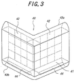
Fig. 3 is a schematic view diagrammatically showing a display apparatus
40 according to a second embodiment of the present invention. This display
apparatus 40 is similar to the first embodiment described above, except that a light
guide plate 41 is of L-shape and arranged such that the center of the light guide plate
41 protrudes toward a viewer. The second embodiment is essentially same as the
first embodiment in that multiple display elements 42 having a tile shape are
arranged on the backside of the light guide plate 41 in close contact with each other.
In the present embodiment, a reflector (not shown) is arranged on the side of the light
guide plate 41 and trough-shaped reflectors 43a, 43b having a bend shape according
to the shape of the light guide plate 41 are arranged on the top and bottom of the light
guide plate 41, respectively. Further, light sources 44 are arranged inside the
reflector 43b that is provided on the bottom of the light guide plate 41. Although
not shown in the drawing, light sources can also be arranged inside the reflector 43a
that is provided on the top of the light guide plate 41.
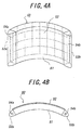
Figs. 4A and 4B are schematic views diagrammatically showing a
display apparatus 50 according to a third embodiment of the present invention. In
this embodiment, the light guide plate 51 of the display apparatus 50 is formed to
have a curved surface with a predetermined curvature, with the center of the light
guide plate 51 protruding in a direction away from the viewer. Multiple display
elements 52 having a tile shape are arranged on the backside of the light guide plate
51, in close contact with each other. Also, trough-shaped reflectors 53a, 53b are
arranged on the sides of the light guide plate 51 and light sources 54a, 54b are
arranged inside the reflectors 53a, 53b. The reflectors 53a, 53b and the light
sources 54a, 54b may be arranged on the top and/or bottom of the light guide plate
51. Incidentally, in the embodiment shown in Figs. 4A and 4B, the display
elements 52 are arranged over the entire area of the backside of the light guide plate
51. However, the display elements 52 may be arranged only locally in the backside
of the light guide plate 51.
When the light guide plate is formed to have a curved surface, as in the
present embodiment, it is important to properly control the angle of incidence by
such means as adjusting the curvature of the light guide plate and/or location of the
light source, etc., to thereby prevent leakage of the incident light from the light
source. To this end, for example, it is desirable to use a light source for launching
light as substantially parallel light without scattering the light. As such a light
source, for example, it is preferred to use a metal halide light source (MME-250
type) manufactured and sold by Moritex Corp., together with a light guide
(MKP180-1500S type) also manufactured and sold by Moritex Corp. The incident
angle of the light with respect to the light guide plate can also be suitably controlled
by arranging a biconvex lens or flat/convex lens having a flat surface and a convex
surface on opposite sides, between the light source and the opposite surface of the
light guide plate.
Figs. 5A and 5B are schematic views diagrammatically showing a
display apparatus 60 according to a fourth embodiment of the present invention. In
this embodiment, although the light guide plate 61 of the display apparatus 60 is
formed to have a curved surface with a predetermined curvature as in the third
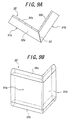
embodiment described above, the center of the light guide plate 61 protrudes in a
direction toward a viewer. In other respect, the fourth embodiment is has basically
the same structure as the third embodiment. That is, multiple display elements 62
having a tile shape are arranged on the backside of the light guide plate 61, in close
contact with each other. Also, trough-shaped reflectors 63a, 63b are arranged on
the sides of the light guide plate 61 and light sources 64a, 64b are arranged inside the
reflectors 63a, 63b. The reflectors 63a, 63b and the light sources 64a, 64b may also
be arranged on the top and/or bottom of the light guide plate 61. Here also, it is not
an essential condition that the tile-shaped display elements 62 be arranged over the
entire area of the backside of the light guide plate 61 is not an essential. Thus, for
example, the display apparatus 60 may be formed to have a configuration in which
the display elements 62 are not arranged in the back area of the light guide plate 61
adjacent to the trough-shaped reflectors 63a, 63b, as shown in Fig. 5B.
Figs. 6A and 6B are schematic views diagrammatically showing a
display apparatus 70 according to a fifth embodiment of the present invention. This
display apparatus 70 is constructed by joining and placing a pair of right and left
display units 71a, 71b so as to form a predetermined angle relative to each other,
with a joint angle of the display units 71a, 71b being set to an angle at which the joint
portion of the display units 71a, 71b protrudes toward a viewer. Multiple display
elements 73a, 73b having a tile shape are arranged on the backsides of light guide
plates 72a, 72b in close contact with each other. A light source 74 extending along
the sides of the light guide plates 72a, 72b and a roof-shaped reflector 75 for
shielding the front side of the light source 74 are arranged in a space between the
opposite sides of the light guide plates 72a, 72b at the joint portion of the display
units 71a, 71b. Also, trough-shaped reflectors 76a, 76b are arranged on those sides
of the light guide plates 72a, 72b, that are located remote from the joint portion of the
display units 71a, 71b, and light sources 77a, 77b are arranged inside these reflectors
76a, 76b. Incidentally, the light sources and the reflectors may be arranged on the
top and/or bottom of the light guide plates 72a, 72b.
Figs. 7A and 7B are schematic views diagrammatically showing a
display apparatus 80 according to a sixth embodiment of the present invention.
This display apparatus 80 is similar to the fifth embodiment described above, except
that a columnar transparent body 83 having a predetermined sectional shape is
arranged in the space formed by light guide plates 82a, 82b at a joint portion of a pair
of display units 81a, 81b that are joined and arranged so as to form a predetermined
angle relative to each other. It is assumed that the transparent body 83 are
maintained in a non-contact state with respect to the sides of the light guide plates
82a, 82b. Also, light absorption layers 84a, 84b are provided on the top and bottom
of the transparent body 83. Multiple display elements 85a, 85b having a tile shape
are arranged on the backsides of light guide plates 82a, 82b, in close contact with
each other. Further, trough-shaped reflectors 86a, 86b are arranged on the top and
bottom of the light guide plates 82a, 82b, and light sources are arranged inside these
reflectors 86a, 86b. Incidentally, as in the embodiment Fig. 5B, the display
apparatus 80 according to the present embodiment is formed into a configuration in
which the display elements 85a, 85b are not arranged on those areas in the backside,
which are adjacent to the sides of the light guide plates 82a, 82b.
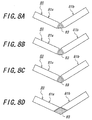
Figs. 8A to 8D illustrate a sectional shape of the columnar transparent
body 83 in the sixth embodiment described above. The sectional shape of the
transparent body 83 is triangle in Fig. 8A, sector in Fig. 8B, quadrilateral in Fig. 8C
that is formed by joining a pair of mutually symmetric scalene triangles at their bases,
and rhombic in Fig. 8D.
Figs. 9A and 9B are schematic views diagrammatically showing a
display apparatus 90 according to a seventh embodiment of the present invention.
This display apparatus 90 is similar to the fifth and sixth embodiments described
above, in that a pair of display units 91a, 91b are joined and arranged so as to form a
predetermined angle relative to each other, though the sides of light guide plates 92a,
92b at the joint portion are in contact with each other through a metal layer 93 that
functions as a reflector layer and also as a shielding layer. Multiple display
elements 94a, 94b having a tile shape are arranged on the backsides of the light guide
plates 92a, 92b, in close contact with each other. Further, trough-shaped reflectors
95a, 95b are arranged on the top and bottom of the light guide plates 92a, 92b, and
light sources are arranged inside these reflectors 95a, 95b.
Fig. 10 shows a modified example of the seventh embodiment described
above. In the present example, instead of the reflector layer 93, a light absorption
layer 96 is provided on the sides of the light guide plates 92a, 92b at the joint portion
of the display units 91a, 91b. Incidentally, in the present example, the light sources
and the trough-shaped reflectors 95a, 95b are arranged on those sides of the light
guide plates 92a, 92b, which are remote from the joint portion of the display units
91a, 91b.
Figs. 11A and 11B are schematic views diagrammatically showing a
display apparatus 100 according to an eighth embodiment of the present invention.
In this display apparatus 100, as in the first embodiment described above, the joint
portion of a pair of display units 101a, 101b protrudes in a direction away from the
viewer, though the light guide plates 102a, 102b of the display units 101a, 101b are
of a wedge-like shape in cross-section, with the thickness decreasing gradually
toward the joint portion of the display units 101a, 101b. Multiple display elements
103a, 103b having a tile shape are arranged on the backsides of the light guide plates
102a, 102b, in close contact with each other. Reflectors or light absorbers 104a,
104b are arranged on the sides of the light guide plates 102a, 102b at the joint portion
of the display units 101a, 101b. The reflectors or light absorbers 104a, 104b are
advantageous in they may have a small area. Further, trough-shaped reflectors 105a,
105b are arranged on those sides of the light guide plates 102a, 102b, that are remote
from the joint portion of the display units 101a, 101b, and light sources 106a, 106b
are arranged inside these reflectors 105a, 105b. Incidentally, the light sources and
the trough-shaped reflectors may be arranged on the top and/or bottom of the light
guide plates 102a, 102b as shown by imaginary lines in Fig. 11B.
Figs. 12A and 12B are schematic views diagrammatically showing a
display apparatus 110 according to a ninth embodiment of the present invention.
This display apparatus 110 is similar to the eighth embodiment described above,
though the joint portion of a pair of display units 111a, 111b protrudes toward the
viewer. Thus, in the present embodiment also, the light guide plates 112a, 112b of
the display units 111a 111b have a wedge-like shape in cross-section, with the
thickness decreasing gradually toward the joint portion of the display units 111a,
111b. Multiple display elements 113a, 113b having a tile shape are arranged on the
backsides of the light guide plates 112a, 112b, in close contact with each other. A
reflector or light absorber 114 is arranged on the sides of the light guide plates 112a,
112b at the joint portion side of the display units 111a, 111b. This reflector or light
absorber 114 is advantageous in that it may have a small area. Further, trough-shaped
reflectors 115a, 115b are arranged on those sides of the light guide plates
112a, 112b, which are remote from the joint portion of the display units 111a, 111b,
and light sources are arranged inside these reflectors 115a, 115b. Incidentally, the
light sources and the trough-shaped reflectors may be arranged on the top and/or
bottom of the light guide plates 112a, 112b.
Next, explanation will be made of certain examples in terms of arranging
the display elements with respect to a light guide plate of a display apparatus
according to the present invention.
First, Fig. 13 shows a general example in which a display element 121a
having an approximately square shape is arranged in a grid-like regular manner with
respect to a light guide plate 120. However, the arranging method of the display
elements with respect to the light guide plate 120 is not limited to only such an
example. Thus, for example, the display elements 121a having an approximately
square shape may be inclined and arranged as shown at the center of Fig. 14.
Further, the display elements 121b, 121c shown on the upper left region of Fig. 14
are formed in a rectangle or triangle, the display clement 121d shown in the lower
left region are formed in a regular triangle, and the display element 121e shown in
the right region is formed in a regular hexagon, respectively. In any case, basically,
multiple display elements having the same shape are arranged on the backside of the
light guide plate 120 in close contact with each other.
Also, the shape of the light guide plate 120 is not limited to square or
rectangle. For example, the embodiment shown in Fig. 15 has a configuration in
which the light guide plate 120 is formed in a cross-shape, and five display elements
121 having a substantially square shape are arranged on the backside of the light
guide plate 120 forming a similar a cross-shape. Such an embodiment minimizes
the cost of the entire apparatus by arranging the necessary minimum number of
display elements at the required region only. Incidentally, with regard to the shape
of the light guide plate or arrangement form of the display elements, it is of course
that various modified forms other than the above may be made.
It has been described above that arrangement of tile-shaped display
elements in the entire back surface of the light guide plate is not an essential
condition. Thus, there will be described below certain configuration examples
wherein the display element is locally eliminated for an intended purpose.
The embodiment shown in Fig. 16 has a basic configuration in which
multiple display elements 131 having a substantially square shape are arranged on
the backside of a light guide plate 130, though a blank region 132 free from the
display element 131 is provided at the center of the light guide plate 130, and a light
emission body, white scattering body or light absorber 133 and the like is arranged
instead of some of the display elements 131.
In this instance, the blank region 132 may be formed of a hollow region,
as shown in Fig. 21A. It is preferable to provide a reflector 135 inside the hollow
blank portion 132. Such a hollow blank portion 132 may be used as a window
frame, or may be used to arrange input devices or suitable artistic object therein.
Also, when the blank portion is a solid portion, as shown in Fig. 21B, it is possible to
easily and positively improve the positioning accuracy of the display element 131 by
arranging a light guide support 134 similar to the above on the backside of the light
guide plate 130.
Fig. 17 is a sectional view showing the blank region 132 in the
embodiment of Fig. 16. Also, Fig. 18A shows an example in which the light
emission body, white scattering body or light absorber 133 and the like is arranged
directly on the backside of the light guide plate 130. In this case, the light emission
body, while scattering body or light absorber 133 and the like may be used to
represent a mark, for example, a character "b". The mark, which is represented by
the light emission body, white scattering body or light absorber 133 and the like, may
be emitted, scattered or absorbed by light introduced into the light guide plate 130, so
as to be visible from outside, as shown in Fig. 18B. The character "b" in this case
differs from a video image displayed by the display apparatus, and is used as a static
information or immovable message. The light emission body, white scattering body
or light absorber 133 and the like may be arranged on the backside of the light guide
support 134 made of the same material as the light guide plate 21 of the display
element 10 shown in Fig. 1, with the light guide support 134 being arranged on the
backside of the light guide plate 130. Figs. 19A and 19B show an example in
which a light emission body 133a and a white scattering body 134b are arranged on
the backside of a light guide support 134, and a character "b" is represented by the
light emission body 133a. When such light guide support 134 is arranged directly
on the backside of a light guide plate 130, as shown in Fig. 20A, the thickness of the
light guide support 134 is preferably set to the same thickness as the light guide plate
(the light guide plate 21 in Fig. 1) in the display element. Also, the light guide
support 134 carrying the light emission body 133a on its backside may be arranged
spaced from the light guide plate 130 and in the back side, as shown in Fig. 20B. In
this case, the character "b" represented by the light emission body 133a is emitted by
light incident from the front surface of the light guide plate 130 so as to be visible
from outside, as in the case of Fig. 18B.
As a modified example of the configuration shown in Fig, 16, a general-purpose
input device such as a button operated by a user can also be arranged in the
blank region provided in the light guide plate of a display apparatus, so that the
apparatus according to the present invention may be used as an interactive display
apparatus.
In the display apparatus according to the present invention, it is not
necessary that the display elements arranged on the backside of the light guide plate
have the same specifications. Thus, for example, a part of the display apparatus
may be formed into a color image display region with high definition and another
part may be formed into a black-and-white or monochromatic high-brightness
message display region. Also, the size of dots in a part of the display apparatus
may be varied relative to the size of dots in the remaining part.
For example, as shown in Fig. 22, it is possible to provide a light guide
plate 130 with display elements 131 corresponding to a color image display region, a
light absorber 133 and its support 134 corresponding to static information or
immovable message, a support region 134 with increased size of dot as compared
with the color image display region to achieve higher brightness and reduction in
electric power consumption, and a region 131' for achieving even higher brightness
by using white or monochromatic display.
The display apparatus according to the present invention explained above
with reference to various embodiments differs from a liquid crystal display or a
plasma display in that a seal structure is not required. Thus, it is possible to realize
a display element having a divided panel structure that is highly suitable for upsizing
and reduction in thickness of the panel without particular difficulties. Also, since
the display element is of direct viewing type, it is readily possible to achieve high
contrast and satisfactory resistance to color fading even when irradiated by external
light, besides that a more excellent view angle can be obtained in comparison with
CRT. By utilizing such advantages, the display apparatus according to the present
invention can be suitable used for the following applications.
First, the embodiments shown in Fig. 2, Figs. 4A and 4B and Figs. 11A
and 11B may be used preferably as a comer type television set that is arranged in the
corner of a living room and so on. Further, the embodiments shown in Fig. 3,
Figs. 5A and 5B, Figs. 6A and 6B, Figs. 7A and 7B, Figs. 9A and 9B and Figs. 11A
and 11B may be arranged adjacent to a protrusion of a column, beam, etc. inside a
room, thereby improving use efficiency of space which otherwise may become
useless. In addition, by combining the embodiments shown in Fig. 2, Figs. 4A and
4B and Figs. 11A and 11B with the embodiments shown in Fig. 3, Figs. 5A and 5B,
Figs. 6A and 6B, Figs. 7A and 7B, Figs. 9A and 9B and Figs. 12A and 12B, it is
readily possible to implement a display apparatus with a stair shape or a folding
screen shape.
The display apparatus according to the present invention can relatively
easily cope with upsizing and thickness reduction of a panel and can be implemented
even, for example, in a large display plane of 300 inches. Also, since the display
element is of direct viewing type, it is readily possible to achieve high contrast and
satisfactory resistance to color fading even when irradiated by external light, besides
that a more excellent view angle can be obtained in comparison with CRT. Thus,
the display apparatus according to the present invention can also be used preferably
as a video image display plane in a cinema complex. In this case, because of the
direct viewing type, the need for space for installation of, for example, a projector etc.
can be eliminated and used as a space for audience.
Also, the display apparatus according to the present invention can easily
adopt a divided panel structure so that it can be arranged as a band-like display with
an extreme aspect ratio, for example, extending along a wall of passage which people
traffic. In this case, it is preferred that a sensor for detecting the traffic of people is
connected to the display apparatus such that vide image is displayed on a light guide
plate when the traffic of people is detected by the sensor.
Further, since the display apparatus according to the present invention is
may be formed as a curved surface display having any desired three-dimensional
shape. Thus, for example, it is readily possible to implement a cylindrical or
pseudo-cylindrical display apparatus, or a spherical or pseudo-spherical display
apparatus.
Still another embodiment will be explained below, in which the display
apparatus according to the present invention is applied to a planetarium.
In order to represent constellations or stars such as a fixed star, a planet
or a satellite (hereinafter collectively called "star"), conventionally, a projector
manufactured optically accurately is precisely installed at a predetermined place
without significant error, so that a light spot is projected onto a large dome-shaped
screen manufactured accurately, by mechanically operating the projector. It
naturally takes considerable time and effort to accurately manufacture such a large
dome-shaped screen and the cost increased accordingly, besides that a certain degree
of uneven error or distortion had to be accepted. Also, since it is necessary to
accurately manufacture the optical projector and represent revolution of Star mainly
by rotation of the projector, the structure becomes highly complicated and the cost
increases accordingly, besides that it takes time and effort for repair, maintenance
and so on. Further, since the star is a light spot projected on the dome-shaped
screen, for example, disturbance light associated with opening and closing of the
doorway was reflected by the screen and distinction was difficult. As a result of
that, the coming and leaving of audience during the showing cycle had to be limited.
When the display apparatus according to the present invention is applied
to a planetarium, since the star is represented by a group of pixels on a display, the
accuracy of the apparatus is not required, and the space for installation of the
projector conventionally required at the center of the planetarium becomes
unnecessary, so that the seating capacity of the facilities can be increased accordingly.
Also, since the revolution of star is represented by a group of pixels on the display,
video software can be relatively easily implemented with which any stars (fixed star,
planet or shooting star) can be represented simply. Further, since the equipment
costs of the dome-shaped screen manufactured accurately or the projector
manufactured optically accurately, etc. are not required, the size of the seating
capacity of the planetarium can be designed relatively freely.
By providing the outermost surface of a display with a light absorption
layer or light reflective layer that is reflective in a constant direction, and also
optionally providing the light guide plate with a light refractive layer of air layer etc.,
the disturbance light associated with opening and closing of the doorway
(corresponding to a blank region of Fig. 16) can be absorbed or reflected in the
constant direction by the outermost surface of the display. As a result, the
disturbance light can clearly be distinguished from the star that is represented by a
group of pixels on the display and the limitation for the comings and leaving of
audience during the showing cycle can be eliminated. Therefore, for example, it is
possible to propose new service forms of complex planetarium/restaurant equipped
with a table with stand light, wherein the center inside seats of the planetarium serves
to display a constellation show utilizing earphone set, and the outer periphery portion
is used for enjoyment of dinner while viewing a starry sky, etc.
Incidentally, even when a video display surface of the planetarium is
constructed by a plane display arranged in a polyhedron shape, for example, a regular
icosahedron shape, the star is represented by a group of pixels, so that, for example,
by increasing the area of a group of pixels for representing the star as it moves from
the center portion of the plane display to the periphery portion, the star can be
represented as if the star is moving on a curved surface when observed by a viewer.
Also, with regard to the size of light spot representing a star in the vicinity of the
viewer (i.e., in the vicinity of "the horizon" of the planetarium) and the size of light
spot representing a star in the vicinity of vertex of the viewer (i.e., in the vicinity of
zenith of the planetarium), it is preferred that the size in the zenith has an increased
size, since otherwise, the star cannot be observed to have a constant size when
observed by a viewer. According to the present invention, the size and density of
pixels in the vicinity of the horizon and the size and density of pixels in the vicinity
of zenith can be selected relatively freely, so that the size of the star can be kept
visually constant when the light spot is observed by a viewer, regardless of the height.
Such projection software can be made relatively simply.
While the display apparatus according to the present invention has been
described above in great detail with reference to the preferred embodiments, it is
needless to say that various changes may be made without departing from the scope
of the invention. The term "video image" used herein encompasses a visual
image derived from any source.