EP1220063B1 - Dynamische Systeme nicht geradzahliger Ordnung - Google Patents
Dynamische Systeme nicht geradzahliger Ordnung Download PDFInfo
- Publication number
- EP1220063B1 EP1220063B1 EP00128558A EP00128558A EP1220063B1 EP 1220063 B1 EP1220063 B1 EP 1220063B1 EP 00128558 A EP00128558 A EP 00128558A EP 00128558 A EP00128558 A EP 00128558A EP 1220063 B1 EP1220063 B1 EP 1220063B1
- Authority
- EP
- European Patent Office
- Prior art keywords
- block
- neural network
- derivative
- integral
- circuit
- Prior art date
- Legal status (The legal status is an assumption and is not a legal conclusion. Google has not performed a legal analysis and makes no representation as to the accuracy of the status listed.)
- Expired - Lifetime
Links
- 238000013528 artificial neural network Methods 0.000 claims description 26
- 230000006870 function Effects 0.000 claims description 17
- 210000002569 neuron Anatomy 0.000 claims description 15
- 230000009021 linear effect Effects 0.000 claims description 6
- 238000004422 calculation algorithm Methods 0.000 claims description 3
- 238000005303 weighing Methods 0.000 claims 6
- 230000004044 response Effects 0.000 description 12
- 238000012546 transfer Methods 0.000 description 11
- 230000005540 biological transmission Effects 0.000 description 10
- 230000010354 integration Effects 0.000 description 6
- BASFCYQUMIYNBI-UHFFFAOYSA-N platinum Chemical compound [Pt] BASFCYQUMIYNBI-UHFFFAOYSA-N 0.000 description 6
- 230000000739 chaotic effect Effects 0.000 description 5
- 230000010287 polarization Effects 0.000 description 5
- 239000007787 solid Substances 0.000 description 5
- 238000010586 diagram Methods 0.000 description 4
- 230000006399 behavior Effects 0.000 description 3
- 230000001939 inductive effect Effects 0.000 description 3
- 229910052697 platinum Inorganic materials 0.000 description 3
- 238000012545 processing Methods 0.000 description 3
- 238000012549 training Methods 0.000 description 3
- 230000008901 benefit Effects 0.000 description 2
- 210000004027 cell Anatomy 0.000 description 2
- 238000013527 convolutional neural network Methods 0.000 description 2
- 238000010587 phase diagram Methods 0.000 description 2
- 238000005293 physical law Methods 0.000 description 2
- BQCADISMDOOEFD-UHFFFAOYSA-N Silver Chemical compound [Ag] BQCADISMDOOEFD-UHFFFAOYSA-N 0.000 description 1
- 238000013459 approach Methods 0.000 description 1
- 230000015572 biosynthetic process Effects 0.000 description 1
- 238000004364 calculation method Methods 0.000 description 1
- 239000003990 capacitor Substances 0.000 description 1
- 230000001413 cellular effect Effects 0.000 description 1
- 238000004891 communication Methods 0.000 description 1
- 238000013461 design Methods 0.000 description 1
- 230000004069 differentiation Effects 0.000 description 1
- 238000006073 displacement reaction Methods 0.000 description 1
- 230000009977 dual effect Effects 0.000 description 1
- 230000008030 elimination Effects 0.000 description 1
- 238000003379 elimination reaction Methods 0.000 description 1
- 238000011156 evaluation Methods 0.000 description 1
- PCHJSUWPFVWCPO-UHFFFAOYSA-N gold Chemical compound [Au] PCHJSUWPFVWCPO-UHFFFAOYSA-N 0.000 description 1
- 229910052737 gold Inorganic materials 0.000 description 1
- 239000010931 gold Substances 0.000 description 1
- 239000000463 material Substances 0.000 description 1
- 229910052751 metal Inorganic materials 0.000 description 1
- 239000002184 metal Substances 0.000 description 1
- 238000000034 method Methods 0.000 description 1
- 230000001537 neural effect Effects 0.000 description 1
- 230000009022 nonlinear effect Effects 0.000 description 1
- 230000010355 oscillation Effects 0.000 description 1
- 229910052709 silver Inorganic materials 0.000 description 1
- 239000004332 silver Substances 0.000 description 1
- 238000004088 simulation Methods 0.000 description 1
- 239000000126 substance Substances 0.000 description 1
- 238000003786 synthesis reaction Methods 0.000 description 1
- 230000009466 transformation Effects 0.000 description 1
- 238000013519 translation Methods 0.000 description 1
Images


Classifications
-
- G—PHYSICS
- G05—CONTROLLING; REGULATING
- G05B—CONTROL OR REGULATING SYSTEMS IN GENERAL; FUNCTIONAL ELEMENTS OF SUCH SYSTEMS; MONITORING OR TESTING ARRANGEMENTS FOR SUCH SYSTEMS OR ELEMENTS
- G05B11/00—Automatic controllers
- G05B11/01—Automatic controllers electric
- G05B11/36—Automatic controllers electric with provision for obtaining particular characteristics, e.g. proportional, integral, differential
- G05B11/42—Automatic controllers electric with provision for obtaining particular characteristics, e.g. proportional, integral, differential for obtaining a characteristic which is both proportional and time-dependent, e.g. P. I., P. I. D.
-
- G—PHYSICS
- G05—CONTROLLING; REGULATING
- G05B—CONTROL OR REGULATING SYSTEMS IN GENERAL; FUNCTIONAL ELEMENTS OF SUCH SYSTEMS; MONITORING OR TESTING ARRANGEMENTS FOR SUCH SYSTEMS OR ELEMENTS
- G05B13/00—Adaptive control systems, i.e. systems automatically adjusting themselves to have a performance which is optimum according to some preassigned criterion
- G05B13/02—Adaptive control systems, i.e. systems automatically adjusting themselves to have a performance which is optimum according to some preassigned criterion electric
- G05B13/0265—Adaptive control systems, i.e. systems automatically adjusting themselves to have a performance which is optimum according to some preassigned criterion electric the criterion being a learning criterion
- G05B13/027—Adaptive control systems, i.e. systems automatically adjusting themselves to have a performance which is optimum according to some preassigned criterion electric the criterion being a learning criterion using neural networks only
Definitions
- the present invention relates to dynamic systems and was developed by paying specific attention to the possibility of implementing non-integer order dynamic systems such as, for example, PID (Proportional, Integral, Derivative) controllers.
- PID Proportional, Integral, Derivative
- fractional integro-differential operators i.e. derivatives and integrals
- derivatives and integrals the idea of fractional integro-differential operators (i.e. derivatives and integrals) seems to be a somehow strange topic, very hard to explain, due to the fact that, unlike commonly used differential operators, it is not related to some direct geometrical meaning, such as the trend of functions or their convexity.
- N the degree of the system.
- the theory of Laplace transforms in the case of linear systems provides the possibility of analysing the input-output relationship of a system via the ratio of its Laplace transform, which is called the "Transfer Function" of the system and whose denominator is a polynomial of degree N.
- the present invention aims at providing a circuit arrangement adapted to implement non-integer order dynamic systems, such as e.g. non -integer order PID controllers.
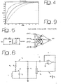
- Bode diagrams that is one of the basic tools in system and control theory.
- fractional order m modulates the slope of the magnitude diagram, providing a parameter useful e.g. for the open loop synthesis of a controller.
- n is an integer such that n -1 ⁇ q ⁇ n .
- Expression (11) is very useful in order to calculate the inverse Laplace transform of elementary transfer functions, such as non integer order integrators (1/s q ).
- the Dirac impulse by means of the definition (1), it holds that: that is the impulse response of a non integer order integrator.
- dielectric mediums can be modeled as distributed parameter systems, their behavior can be analysed in a way similar to what has been done for transmission lines.
- (22) can be considered as a cascade of three single poles fractional order systems and each of them may be studied separately in frequency domain.
- the integral extended to the whole interval [0, t ] may be decomposed into the sum of k integrals:
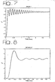
- Fig. 6 the so-called Chua circuit is shown, providing for the presence of a chaotic variable V R and a differentiating circuit.
- the feedback signal which is proportional to the time derivative of V R , continuously modulates the negative resistance value of the Chua diode R N .
- a continuous feedback proportional to the derivative of the chaotic signal, can be used.
- the present invention relates to a non-integer PID controller having the features set forth in the preamble of Claim 1.
- a controller is known, per se , from I. Podlubry: "Fractional order systems and PID-controllers" IEEE Transactions on Automatic Control, vol. 44, no. 1, January 1999.
- the invention is characterised by the further features set forth in Claim 1.
- analog design implies the realization of a time varying capacitors usually difficult to modulate according to desired trend (see e.g. the work edited by B. Ross already cited in the foregoing) and digital circuitry needs a large memory area to store function samples.
- a neural network modeling may guarantee, at the same time, a good degree of approximation and the possibility, by keeping a fixed structure, of changing the integration order by well-defined configuration of weights. Also an hardware realization of the obtained networks can be easily designed.
- This equation can be implemented by means of a neural network and, as predicted in the theory of black box identification, the network in question must have 38 inputs and 1 output.
- the number of neurons in the hidden layer can be set initially to 20 and then moved to 25 so the total number of weights is 950.
- FIG. 9 shows the multi-layer perceptron adopted for the simulation of the m-order integrator (38-25-1).
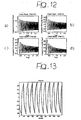
- the frequencies contained in the signal are the odd ones (10, 30, 50, 70 Hz) and have appreciable amplitude until 190 Hz.
- Fig. 13 shows the results of order 0.3 integration of a square wave.
- the output of the network (dashed) is very close to the real one (solid).
- references 1 and 2 designate input and output sections of a neural network adapted to receive OSan input signal IS and to deliver an output signal OS, respectively.
- Reference 3 designates the core of the network
- references 4 and 5 designate input/output and memory blocks, respectively.
- Arrows 1-3, 2-1, 3-1, 3-2, 3-4 and 3-5 show flow of data between the various blocks considered in the foregoing.
- the weights w j and the bias values b i (i.e. the coefficients) of the neural network, previously determined by using the back propagation algorithm, are acquired through an I/O port 4 and then stored into the memory block 5.
- the input signal IS (X) is acquired and loaded into a shift register (S 1 ), controlled by the core 3.
- the core 3 control unit manages also the shift register S 2 , utilized for the feedback of the output.
- the core For each input stored in the shift registers S 1 and S 2 , the core, reads the appropriate weights, moves it in blocks ⁇ ( ⁇ ) i (designated 20) that calculate the input for the each neuron, according to the formula: ⁇ (w j x i )+b i .
- Another ⁇ ( ⁇ ) block (designated 23) realizes the output layer that received the input from the previous layer and the weights and bias from the core; it calculates the neural network output OS.
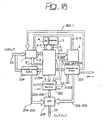
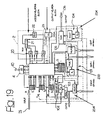
- a PID (Proportional, Integral, Differential) controller consists (as shown in Fig. 17) of three main blocks: an integrator 100 plus an (integral) gain 101, a derivator 102 with a corresponding (derivative) gain 103 and one proportional block 104. By properly setting the respective gains these blocks act on the input signal providing the output control variable which is obtained by means of an adder 105 summing the results of integration, differentiation and proportional gain.
- references 200, 202, 204 and 205 designate blocks which applying to the signals fed thereto respective integral (200), derivative (202) and proportional (204) processing.
- An adder generating the main output signal OS is designated 205. Transfer of data takes place along lines designated, as in the foregoing, by the references of the respective interconnected blocks separated by a hyphen.
- the derivative block 202 is obtained from the integrator one 200.
- the not integer order derivative is the integer order derivative of an opportune not integer order integral (see equation (4)).
- the weights and the bias of the neural network previously determined by using the back propagation algorithm are acquired through the I/O port 40 and then stored into the memory block 5.
- the input signal IS (X) is acquired and loaded into a shift register S 1 , controlled by the core.
- the core control unit manages also the shift registers S 2 and S 3 , utilized for the feedback of the integrator and derivative outputs.
- the core 3 For each input stored in the shift register S 1 -S 3 , the core 3, reads the appropriate weights and moves it in the blocks ⁇ ( ⁇ ) i 20 that calculate the input for the each neuron, according to the formula: ⁇ (w j x i )+b i .
- the ⁇ ( ⁇ ) block 23 (SUM out ) realizes the output layer that received the input from the previous layer and the weights and bias from the core; it calculates the neural network output.
- the output of the block 23 is sent alternatively to the S2 shift register or to the derivative block 204.
- the core 3 manages this switching.
- the core unit 3 has to load from the memory block once the data to compute the former and once the data for the latter, processing always the same input.
- Two multiplexers are additionally provided, which are designated MUX1 and MUX2.
- MUX1 managed via the core, it is possible to receive, and then manage, a derivative term D-EXT computed outside: for example a simple derivative term computed by an analogous device.
- connection scheme of two non-integer PI ⁇ D ⁇ controllers I and II is given in Fig. 20, where the same reference numerals are reproduced which were already used in Fig. 18.
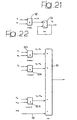
- Fig. 21 provides for the presence of a product block 50 followed by a recursive adder block 51.
- FIG. 22 Another possible implementation is the one shown in Fig. 22 providing for the presence of a plurality of multiplier blocks 50l, ..., 50N whose outputs are fed to a single non-recursive adder block 51.
- the output sum value of adder 51 is controlled by a bias line 52.
Landscapes
- Engineering & Computer Science (AREA)
- Artificial Intelligence (AREA)
- Physics & Mathematics (AREA)
- General Physics & Mathematics (AREA)
- Automation & Control Theory (AREA)
- Evolutionary Computation (AREA)
- Health & Medical Sciences (AREA)
- Computer Vision & Pattern Recognition (AREA)
- Medical Informatics (AREA)
- Software Systems (AREA)
- Feedback Control In General (AREA)
- Complex Calculations (AREA)
Claims (12)
- PID-Regler nicht ganzzahliger Ordnung, daran angepasst, wenigstens ein Eingangssignal (IS) zu empfangen, und daraus wenigstens eine Ausgangssignal (OS) zu erzeugen, wobei die Eingangs- und Ausgangssignale (IS, OS) zueinander durch ein integral-differentiales Verhältnis nicht ganzzahliger Ordnung in Bezug stehen, dadurch gekennzeichnet, dass der Regler einen neuronalen Netzwerkschaltkreis (1 bis 5) enthält, und die Koeffizienten (wj, bi) des neuronalen Netzwerks (1 bis 5) dieses integraldifferentiale Verhältnis implementieren, wobei das neuronale Netzwerk wenigstens ein Eingangsschichtregister (SI) enthält, um dieses Eingangssignal (IS) zu empfangen und wenigstens einen Addiererblock 20, um den Eingang eines jeweiligen Neurons des neuronalen Netzwerks basierend auf dem Eingangssignal (IS) und einem entsprechenden Satz von Koeffizienten (wj; bi) zu berechnen, sowie auch wenigstens einen Gewichtungsfunktionsblock (22), um den Ausgang_wenigstens eines Neurons in dem neuronalen Netzwerk auf der Basis einer entsprechenden Gewichtungsfunktion zu berechnen, und worin der Schaltkreis wenigstens eines beinhaltet aus:einem Proportionalblock (204) der daran angepasst ist, um zu diesem Ausgangssignal (OS) eine Eingangssignalkomponente zu addieren (105), welche einem proportionalen Gewichtungskoeffizienten (Kp) ausgesetzt ist,einem Integralblock (200), der daran angepasst ist, um zu diesem Ausgangssignal (OS) eine nicht ganzzahlige Integralssignalkomponente zu addieren (105), welche einem Gewichtungskoeffizienten (Ki) ausgesetzt ist, wobei dem Integralblock ein jeweiliges Eingangsregister (S2) zugeordnet ist, zur Rückführung des Ausgangs des Integralblocks (200) zum Eingang des neuronalen Netzwerks, undeinem Ableitungsblock (202) der daran angepasst ist, um zu diesem Ausgangssignal (OS) eine nicht ganzzahlige Ableitungsssignalkomponente zu addieren (105), welche einem abgeleiteten Gewichtungskoeffizienten (Kd) ausgesetzt ist, wobei dem Ableitungsblock (204) ein jeweiliges Eingangsregister (S3) zugeordnet ist zur Rückführung des Ausgangs des Ableitungsblocks (202) zum Eingang des neuronalen Netzwerkes.
- Schaltkreis von Anspruch 1, dadurch gekennzeichnet, dass das neuronale Netzwerk (1 bis 5) einen Speicher (4) beinhaltet, zur Speicherung der Koeffizienten, wie bestimmt durch einen Back Propagation Algorithmus durch das neuronale Netzwerk.
- Schalkreis von Anspruch 1 oder Anspruch 2, dadurch gekennzeichnet, dass das neuronale Netzwerk einen Eingabeanschluss (40) zum Empfang der Koeffizienten beinhaltet.
- Schaltkreis nach Anspruch 1, dadurch gekennzeichnet, dass das neuronale Netzwerk eine Vielzahl von Neuronen wie auch einen einzigen Multiplexerschaltkreis (22) enthält, um entsprechende Gewichtungsfunktionen auf eine Vielzahl der Neuronen anzuwenden.
- Schaltkreis nach irgendeinem der Ansprüche 1 bis 4, dadurch gekennzeichnet, dass er wenigstens einen Ausgangsschichtaddierschaltkreis (23) enthält, um die Ausgabe des neuronalen Netzwerkes (OS) aus den Ausgaben des wenigstens einen Neurons zu berechnen.
- Vorrichtung nach irgendeinem der Ansprüche 1, 4 oder 5, dadurch gekennzeichnet, dass sie wenigstens eine zusätzliches Schieberegister (S2) der ersten Lage beinhaltet zur Rückführung des Ausgangs (OS) des neuronalen Netzwerks zurück an seinen Eingang.
- Schaltkreis nach irgendeinem der Ansprüche 1, 4, 5 oder 6, dadurch gekennzeichnet, dass das neuronale Netzwerk (1 bis 5) wenigstens einen Neuronenblock beinhaltet, um eine Linearkombination eines jeweiligen Eingangssignals (xi) mit einem Satz von Gewichten (wi) und Verzerrungswerten (bj) zu realisieren, worin der wenigstens eine Neuronenblock einen einzigen Produktblock (50) wie auch einen einzigen Addiererblock (51) enthält, welche diese Linearkombination rekursiv über eine Vielzahl von Taktzyklen implementieren.
- Schaltkreis nach irgendeinem der Ansprüche 1, 4, 5, 6, oder 7, dadurch gekennzeichnet, dass das neuronale Netzwerk (1 bis 5) wenigstens einen Neuronenblock beinhaltet, um eine Linearkombination aus einem jeweiligen Eingangssignal (xi) mit einem Satz von Gewichten (wi) und Verzerrungswerten (bj) zu realisieren, worin der wenigstens eine Neuronenblock eine Vielzahl (501, 502, ..., 50n) von Produktblöcken beinhaltet, welche jeweilige Produkte des Eingangssignals (xi) mit vorgegebenen Gewichten (w1, w2, ...,wn) implementieren, und einen einzigen Addiererblock (51), der simultan die Ergebnisse der Produkte und der Verzerrungswerte (52) addiert.
- Schaltkreis nach Anspruch 1, dadurch gekennzeichnet, dass er sowohl den Integralblock (200) und den Ableitungsblock (202) enthält, worin die nicht ganzzahlige Ableitungssignalkomponente erhalten wird als eine Ableitung ganzzahliger Ordnung und einer nicht ganzzahligen Integralsignalkomponente, die durch den Integralblock 200 erzeugt wird.
- Schaltkreis nach Anspruch 1 oder Anspruch 9, dadurch gekennzeichnet, dass dem Integralblock (200) einen Integraleingabeeingang (MUX2) zugeordnet ist, um einen externen Integralterm zu verwalten.
- Schalkreis nach irgendeinem der Ansprüche 1, 9 oder 10, dadurch gekennzeichnet, dass dem Ableitungsblock (200) ein Ableitungseingangsanschluss (MUX1) zugeordnet ist, um einen externen Ableitungsterm zu verwalten.
- Dynamisches System, das eine Vielzahl (I, II) von Schaltkreisen enthält, nach irgendeinem der Ansprüche 10 oder 11, wobei irgendeiner der Integral- (200) oder Ableitungs- (202) blöcke, welcher in der Vielzahl von Schaltkreisen enthalten ist, wenigstens ein jeweiliges Ausgangssignal erzeugt, welches irgendeinem der Integral- (200) oder Ableitungs- (202) blöcke zugeführt wird, welcher in einem anderen der Vielzahl der Schaltkreise des dynamischen Systems enthalten ist.
Priority Applications (4)
| Application Number | Priority Date | Filing Date | Title |
|---|---|---|---|
| DE60018587T DE60018587D1 (de) | 2000-12-27 | 2000-12-27 | Dynamische Systeme nicht geradzahliger Ordnung |
| EP00128558A EP1220063B1 (de) | 2000-12-27 | 2000-12-27 | Dynamische Systeme nicht geradzahliger Ordnung |
| US10/036,300 US6678670B2 (en) | 2000-12-27 | 2001-12-26 | Non-integer order dynamic systems |
| JP2001396005A JP2002258903A (ja) | 2000-12-27 | 2001-12-27 | 非整数次の動的システム |
Applications Claiming Priority (1)
| Application Number | Priority Date | Filing Date | Title |
|---|---|---|---|
| EP00128558A EP1220063B1 (de) | 2000-12-27 | 2000-12-27 | Dynamische Systeme nicht geradzahliger Ordnung |
Publications (2)
| Publication Number | Publication Date |
|---|---|
| EP1220063A1 EP1220063A1 (de) | 2002-07-03 |
| EP1220063B1 true EP1220063B1 (de) | 2005-03-09 |
Family
ID=8170832
Family Applications (1)
| Application Number | Title | Priority Date | Filing Date |
|---|---|---|---|
| EP00128558A Expired - Lifetime EP1220063B1 (de) | 2000-12-27 | 2000-12-27 | Dynamische Systeme nicht geradzahliger Ordnung |
Country Status (4)
| Country | Link |
|---|---|
| US (1) | US6678670B2 (de) |
| EP (1) | EP1220063B1 (de) |
| JP (1) | JP2002258903A (de) |
| DE (1) | DE60018587D1 (de) |
Cited By (1)
| Publication number | Priority date | Publication date | Assignee | Title |
|---|---|---|---|---|
| CN105629733A (zh) * | 2016-02-01 | 2016-06-01 | 江西理工大学 | 一种分数阶细胞神经网络自适应同步控制及电路设计方法 |
Families Citing this family (10)
| Publication number | Priority date | Publication date | Assignee | Title |
|---|---|---|---|---|
| US7545971B2 (en) * | 2005-08-22 | 2009-06-09 | Honeywell International Inc. | Method and apparatus for measuring the crepe of a moving sheet |
| DE102006003251A1 (de) * | 2006-01-24 | 2007-07-26 | Robert Bosch Gmbh | Verfahren zum Regeln eines Istwertes für eine eine Position eines Stellgliedes charakterisierende Größe, Computerprogramm-Produkt, Computerprogramm und Aufzeichnungsträger |
| EP2558969A4 (de) * | 2010-04-13 | 2013-10-09 | Univ California | Verfahren zur verwendung generalisierter ordnungsunterschiede und zur integration von eingabevariablen in trendvorhersagen |
| CN102970130B (zh) * | 2012-11-19 | 2015-02-18 | 合肥工业大学 | 一种新分数阶混沌电路 |
| CN107148751A (zh) * | 2014-08-20 | 2017-09-08 | 美国莱特州立大学 | 分数标度数字信号处理 |
| CN104468075B (zh) * | 2014-11-11 | 2015-08-19 | 国家电网公司 | 0.3阶混合型分数阶积分电路模块和基于其的含x方Lü混沌系统电路实现 |
| CN104468086B (zh) * | 2014-12-14 | 2016-02-10 | 国网新疆电力公司电力科学研究院 | 一种0.3阶t型分数阶积分电路装置 |
| CN104468084B (zh) * | 2014-12-14 | 2015-12-30 | 国家电网公司 | 一种0.8阶t型分数阶积分电路模块 |
| CN104486062B (zh) * | 2014-12-14 | 2015-09-16 | 国网山东省电力公司泰安供电公司 | 基于0.4阶T型分数阶积分电路模块的Liu混沌系统电路 |
| CN107666184B (zh) * | 2017-10-10 | 2023-07-18 | 华南理工大学 | 基于分数阶电容的无电压源串联-串联型无线电能传输系统 |
Family Cites Families (3)
| Publication number | Priority date | Publication date | Assignee | Title |
|---|---|---|---|---|
| US5111531A (en) * | 1990-01-08 | 1992-05-05 | Automation Technology, Inc. | Process control using neural network |
| DE69225605T2 (de) * | 1991-12-18 | 1998-11-26 | Honeywell, Inc., Minneapolis, Minn. | Auf einem neuronalen netzwerk basierende automatische einstellvorrichtung für einen geschlossenen regelkreis |
| US6578018B1 (en) * | 1999-07-27 | 2003-06-10 | Yamaha Hatsudoki Kabushiki Kaisha | System and method for control using quantum soft computing |
-
2000
- 2000-12-27 EP EP00128558A patent/EP1220063B1/de not_active Expired - Lifetime
- 2000-12-27 DE DE60018587T patent/DE60018587D1/de not_active Expired - Lifetime
-
2001
- 2001-12-26 US US10/036,300 patent/US6678670B2/en not_active Expired - Lifetime
- 2001-12-27 JP JP2001396005A patent/JP2002258903A/ja active Pending
Cited By (2)
| Publication number | Priority date | Publication date | Assignee | Title |
|---|---|---|---|---|
| CN105629733A (zh) * | 2016-02-01 | 2016-06-01 | 江西理工大学 | 一种分数阶细胞神经网络自适应同步控制及电路设计方法 |
| CN105629733B (zh) * | 2016-02-01 | 2018-05-01 | 江西理工大学 | 一种分数阶细胞神经网络自适应同步控制及电路设计方法 |
Also Published As
| Publication number | Publication date |
|---|---|
| DE60018587D1 (de) | 2005-04-14 |
| US6678670B2 (en) | 2004-01-13 |
| US20020133243A1 (en) | 2002-09-19 |
| EP1220063A1 (de) | 2002-07-03 |
| JP2002258903A (ja) | 2002-09-13 |
Similar Documents
| Publication | Publication Date | Title |
|---|---|---|
| Burrascano et al. | A review of artificial neural networks applications in microwave computer‐aided design (invited article) | |
| EP1220063B1 (de) | Dynamische Systeme nicht geradzahliger Ordnung | |
| Liao et al. | Hopf bifurcation and chaos in a single delayed neuron equation with non-monotonic activation function | |
| Tanguy et al. | Optimum choice of free parameter in orthonormal approximations | |
| He et al. | Solutions and memory effect of fractional-order chaotic system: A review | |
| Khanra et al. | Rational approximation and analog realization of fractional order transfer function with multiple fractional powered terms | |
| Fa-Long et al. | Neural network approach to computing matrix inversion | |
| Erickson et al. | Converter transfer functions | |
| Dorcak et al. | Comparison of the methods for discrete approximation of the fractional-order operator | |
| Hui et al. | Discrete transform technique for solving coupled integro-differential equations in digital computers | |
| Barsainya et al. | Optimal design of minimum multiplier lattice wave digital lowpass filter using metaheuristic techniques | |
| Tapche et al. | Uncertain destination of a 4D autonomous system with five line equilibria | |
| Bonet-Dalmau et al. | A discrete-time approach to the steady-state and stability analysis of distributed nonlinear autonomous circuits | |
| Restrepo et al. | Analytical properties of Teager's filter | |
| Letsch et al. | On the construction of a random process with given power spectrum and probability density function | |
| Wu et al. | An analog architecture on parameter estimation of ARMA models | |
| Różowicz et al. | Equivalent diagrams of fractional order elements | |
| Martinelli et al. | Neural network approach to spectral estimation of harmonic processes | |
| Sabatier et al. | Partial Differential Equations with Spatially Variable Coefficients | |
| Gullapalli | Wave-Digital FPGA Architectures of 4-D Depth Enhancement Filters for Real-Time Light Field Image Processing | |
| Kotropoulos et al. | Sorting networks using L/sub p/mean comparators for signal processing applications | |
| Abbisso et al. | Realization of a non integer order PID controller | |
| Battula et al. | Fractional Order Lowpass Filter Realization Using M-SBL Method | |
| Franken | Complex digital networks: A sensitivity analysis based on the Wirtinger calculus | |
| Nunes et al. | Fast algorithm for computing the Abel inversion integral in broadband reflectometry |
Legal Events
| Date | Code | Title | Description |
|---|---|---|---|
| PUAI | Public reference made under article 153(3) epc to a published international application that has entered the european phase |
Free format text: ORIGINAL CODE: 0009012 |
|
| AK | Designated contracting states |
Kind code of ref document: A1 Designated state(s): AT BE CH CY DE DK ES FI FR GB GR IE IT LI LU MC NL PT SE TR |
|
| AX | Request for extension of the european patent |
Free format text: AL;LT;LV;MK;RO;SI |
|
| 17P | Request for examination filed |
Effective date: 20020902 |
|
| AKX | Designation fees paid |
Designated state(s): DE FR GB IT |
|
| 17Q | First examination report despatched |
Effective date: 20030325 |
|
| GRAP | Despatch of communication of intention to grant a patent |
Free format text: ORIGINAL CODE: EPIDOSNIGR1 |
|
| RIN1 | Information on inventor provided before grant (corrected) |
Inventor name: ABBISSO, SALVATORE Inventor name: DIAMANTE, OLGA Inventor name: FORTUNA, LUIGI Inventor name: DI COLA, EUSEBIO Inventor name: CAPONETTO, RICCARDO Inventor name: PORTO, DOMENICO |
|
| GRAS | Grant fee paid |
Free format text: ORIGINAL CODE: EPIDOSNIGR3 |
|
| GRAA | (expected) grant |
Free format text: ORIGINAL CODE: 0009210 |
|
| AK | Designated contracting states |
Kind code of ref document: B1 Designated state(s): DE FR GB IT |
|
| REG | Reference to a national code |
Ref country code: GB Ref legal event code: FG4D |
|
| REG | Reference to a national code |
Ref country code: IE Ref legal event code: FG4D |
|
| REF | Corresponds to: |
Ref document number: 60018587 Country of ref document: DE Date of ref document: 20050414 Kind code of ref document: P |
|
| PG25 | Lapsed in a contracting state [announced via postgrant information from national office to epo] |
Ref country code: DE Free format text: LAPSE BECAUSE OF FAILURE TO SUBMIT A TRANSLATION OF THE DESCRIPTION OR TO PAY THE FEE WITHIN THE PRESCRIBED TIME-LIMIT Effective date: 20050610 |
|
| PLBE | No opposition filed within time limit |
Free format text: ORIGINAL CODE: 0009261 |
|
| STAA | Information on the status of an ep patent application or granted ep patent |
Free format text: STATUS: NO OPPOSITION FILED WITHIN TIME LIMIT |
|
| 26N | No opposition filed |
Effective date: 20051212 |
|
| EN | Fr: translation not filed | ||
| PGFP | Annual fee paid to national office [announced via postgrant information from national office to epo] |
Ref country code: IT Payment date: 20071211 Year of fee payment: 8 |
|
| PG25 | Lapsed in a contracting state [announced via postgrant information from national office to epo] |
Ref country code: FR Free format text: LAPSE BECAUSE OF NON-PAYMENT OF DUE FEES Effective date: 20051231 |
|
| PG25 | Lapsed in a contracting state [announced via postgrant information from national office to epo] |
Ref country code: FR Free format text: LAPSE BECAUSE OF NON-PAYMENT OF DUE FEES Effective date: 20050309 |
|
| PGFP | Annual fee paid to national office [announced via postgrant information from national office to epo] |
Ref country code: GB Payment date: 20101201 Year of fee payment: 11 |
|
| GBPC | Gb: european patent ceased through non-payment of renewal fee |
Effective date: 20121227 |
|
| PG25 | Lapsed in a contracting state [announced via postgrant information from national office to epo] |
Ref country code: GB Free format text: LAPSE BECAUSE OF NON-PAYMENT OF DUE FEES Effective date: 20121227 Ref country code: IT Free format text: LAPSE BECAUSE OF NON-PAYMENT OF DUE FEES Effective date: 20081227 |