EP1220050A2 - Toner replenishing device and image forming apparatus using the same - Google Patents
Toner replenishing device and image forming apparatus using the same Download PDFInfo
- Publication number
- EP1220050A2 EP1220050A2 EP01130525A EP01130525A EP1220050A2 EP 1220050 A2 EP1220050 A2 EP 1220050A2 EP 01130525 A EP01130525 A EP 01130525A EP 01130525 A EP01130525 A EP 01130525A EP 1220050 A2 EP1220050 A2 EP 1220050A2
- Authority
- EP
- European Patent Office
- Prior art keywords
- toner
- lower case
- locking
- upper case
- case
- Prior art date
- Legal status (The legal status is an assumption and is not a legal conclusion. Google has not performed a legal analysis and makes no representation as to the accuracy of the status listed.)
- Granted
Links
Images







Classifications
-
- G—PHYSICS
- G03—PHOTOGRAPHY; CINEMATOGRAPHY; ANALOGOUS TECHNIQUES USING WAVES OTHER THAN OPTICAL WAVES; ELECTROGRAPHY; HOLOGRAPHY
- G03G—ELECTROGRAPHY; ELECTROPHOTOGRAPHY; MAGNETOGRAPHY
- G03G15/00—Apparatus for electrographic processes using a charge pattern
- G03G15/06—Apparatus for electrographic processes using a charge pattern for developing
- G03G15/08—Apparatus for electrographic processes using a charge pattern for developing using a solid developer, e.g. powder developer
- G03G15/0894—Reconditioning of the developer unit, i.e. reusing or recycling parts of the unit, e.g. resealing of the unit before refilling with toner
-
- G—PHYSICS
- G03—PHOTOGRAPHY; CINEMATOGRAPHY; ANALOGOUS TECHNIQUES USING WAVES OTHER THAN OPTICAL WAVES; ELECTROGRAPHY; HOLOGRAPHY
- G03G—ELECTROGRAPHY; ELECTROPHOTOGRAPHY; MAGNETOGRAPHY
- G03G15/00—Apparatus for electrographic processes using a charge pattern
- G03G15/06—Apparatus for electrographic processes using a charge pattern for developing
- G03G15/08—Apparatus for electrographic processes using a charge pattern for developing using a solid developer, e.g. powder developer
- G03G15/0822—Arrangements for preparing, mixing, supplying or dispensing developer
- G03G15/0848—Arrangements for testing or measuring developer properties or quality, e.g. charge, size, flowability
- G03G15/0849—Detection or control means for the developer concentration
- G03G15/0855—Detection or control means for the developer concentration the concentration being measured by optical means
-
- G—PHYSICS
- G03—PHOTOGRAPHY; CINEMATOGRAPHY; ANALOGOUS TECHNIQUES USING WAVES OTHER THAN OPTICAL WAVES; ELECTROGRAPHY; HOLOGRAPHY
- G03G—ELECTROGRAPHY; ELECTROPHOTOGRAPHY; MAGNETOGRAPHY
- G03G15/00—Apparatus for electrographic processes using a charge pattern
- G03G15/06—Apparatus for electrographic processes using a charge pattern for developing
- G03G15/08—Apparatus for electrographic processes using a charge pattern for developing using a solid developer, e.g. powder developer
- G03G15/0822—Arrangements for preparing, mixing, supplying or dispensing developer
- G03G15/0865—Arrangements for supplying new developer
-
- G—PHYSICS
- G03—PHOTOGRAPHY; CINEMATOGRAPHY; ANALOGOUS TECHNIQUES USING WAVES OTHER THAN OPTICAL WAVES; ELECTROGRAPHY; HOLOGRAPHY
- G03G—ELECTROGRAPHY; ELECTROPHOTOGRAPHY; MAGNETOGRAPHY
- G03G15/00—Apparatus for electrographic processes using a charge pattern
- G03G15/06—Apparatus for electrographic processes using a charge pattern for developing
- G03G15/08—Apparatus for electrographic processes using a charge pattern for developing using a solid developer, e.g. powder developer
- G03G15/0822—Arrangements for preparing, mixing, supplying or dispensing developer
- G03G15/0865—Arrangements for supplying new developer
- G03G15/0867—Arrangements for supplying new developer cylindrical developer cartridges, e.g. toner bottles for the developer replenishing opening
- G03G15/087—Developer cartridges having a longitudinal rotational axis, around which at least one part is rotated when mounting or using the cartridge
- G03G15/0872—Developer cartridges having a longitudinal rotational axis, around which at least one part is rotated when mounting or using the cartridge the developer cartridges being generally horizontally mounted parallel to its longitudinal rotational axis
-
- G—PHYSICS
- G03—PHOTOGRAPHY; CINEMATOGRAPHY; ANALOGOUS TECHNIQUES USING WAVES OTHER THAN OPTICAL WAVES; ELECTROGRAPHY; HOLOGRAPHY
- G03G—ELECTROGRAPHY; ELECTROPHOTOGRAPHY; MAGNETOGRAPHY
- G03G2215/00—Apparatus for electrophotographic processes
- G03G2215/06—Developing structures, details
- G03G2215/066—Toner cartridge or other attachable and detachable container for supplying developer material to replace the used material
- G03G2215/0663—Toner cartridge or other attachable and detachable container for supplying developer material to replace the used material having a longitudinal rotational axis, around which at least one part is rotated when mounting or using the cartridge
- G03G2215/0665—Generally horizontally mounting of said toner cartridge parallel to its longitudinal rotational axis
-
- G—PHYSICS
- G03—PHOTOGRAPHY; CINEMATOGRAPHY; ANALOGOUS TECHNIQUES USING WAVES OTHER THAN OPTICAL WAVES; ELECTROGRAPHY; HOLOGRAPHY
- G03G—ELECTROGRAPHY; ELECTROPHOTOGRAPHY; MAGNETOGRAPHY
- G03G2215/00—Apparatus for electrophotographic processes
- G03G2215/08—Details of powder developing device not concerning the development directly
- G03G2215/0855—Materials and manufacturing of the developing device
- G03G2215/0872—Housing of developing device
Definitions
- the present invention relates to a copier, facsimile apparatus, printer or similar image forming apparatus and more particularly to a toner replenishing device for replenishing toner to a developing device included in the image forming apparatus.
- the toner cartridge stores fresh toner, or developer, to be replenished to a developing device included in the image forming apparatus.
- the toner cartridge usually has a double-wall structure made up of a toner bottle or toner container storing toner and a case encasing the toner bottle.
- the double-wall structure protects the toner from heat and moisture.
- a toner cartridge with this configuration is disclosed in, e.g., Japanese Patent Laid-Open publication Nos. 6-194950 and 10-69160.
- the toner cartridge has a sophisticated configuration and is expensive and is therefore often reused or recycled when it runs out of toner.
- the replacement of the toner cartridge should preferably be performed by an expert as distinguished from the user. If the user replaces the toner bottle, then it is likely that the body of the toner replenishing device is damaged due to inadequate assembling or that the toner flies about when the case of the toner cartridge is disassembled.
- the toner cartridge is therefore configured on the assumption that the user does not replace the toner bottle; that is, the entire toner cartridge is replaced when the toner bottle runs out of toner.
- the case formed with an opening for receiving the toner bottle and a cover for closing the opening are simply snap-fitted on each other and therefore easy to disassemble.
- This configuration tempts the user to disassemble the case and replace only the toner bottle or to refill the empty toner bottle. It is therefore impossible to fully solve the problems discussed above.
- the case and cover snap-fitted on each other are easy to assemble, i.e., surely connectable to each other.
- the case and cover may be lightly snap-fitted on each other to facilitate disassembly. Light snap-fitting, however, obstructs the sure connection of the case and cover and is apt to cause the cover to be released from the case due to a shock or an impact during transport. In these circumstances, there is an increasing demand for a case realizing both of easy disassembly and sure connection and solving the problems ascribable to disassembly by the user.
- PET polyethylene terephthalate
- PE polyethylene
- Laid-Open Publication Nos. 6-194950 and 10-69160 mentioned earlier disclose toner bottles configured to deform or break little when subjected to a shock or an impact.
- the toner bottles each are of screw type and encased in a rectangular case.
- the screw type toner bottle is rotated about its axis to discharge toner stored therein via a mouth.
- a gear is mounted on the circumference of the toner bottle.
- a drive gear mounted on the body of an image forming apparatus is brought into mesh with the above gear.
- rotation transferred to the toner bottle via such a gear train is apt to cause the toner bottle to oscillate, resulting in unstable toner replenishment.
- Another drive transmission system proposed in the past uses a drive member that engages with the bottom of the toner bottle and rotates coaxially with the toner bottle.
- This drive transmission system causes the toner bottle to oscillate less than the drive transmission system that transfers rotation to the circumference of the toner bottle.
- the drive member scheme directly applies the oscillation of a drive source to the toner bottle, failing to stabilize toner replenishment.
- the afore-mentioned problem is solved by the subject malte of the independent claims 1, 9, 10, 16, 17, 19, 21, 23, and 27.
- Dependent claims are directed to embodiments of advantage.
- a toner replenishing device of the present invention includes a casing for accommodating a toner.
- the casing is made up of a lower case formed with an opening for receiving the toner container, and an upper case for covering the opening of the lower case.
- a locking member locks the upper case closing the opening to the lower case.
- the locking member is configured to loose the function of locking the upper case to the lower case when unlocking the former from the latter.
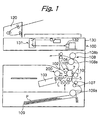
- an image forming apparatus embodying the present invention is shown and implemented as a copier by way of example.
- the copier includes a photoconductive element or image carrier implemented as a drum 7.
- the drum 7 has an OPC (Organic PhotoConductor) or similar photoconductive layer and rotates counterclockwise, as viewed in FIG. 1.
- OPC Organic PhotoConductor
- Arranged around the drum 7 are a charge roller or charging means 102, an optical writing unit or exposing means 103, a developing unit or developing means 1, an image transfer roller or image transferring means 110, a cleaning blade or cleaning means 105, and a discharge lamp or discharging means 106.
- the charge roller 102 to which a high voltage is applied, uniformly charges the surface of the drum 7 to negative polarity.
- An ADF (Automatic Document Feeder) 120 is mounted on the top of a printer body 100.
- a scanner 130 includes optics 131 and a CCD (Charge Coupled Device) array or similar image sensor 132.
- the image sensor 132 reads image information out of the document via the optics 131.
- the optical writing unit 103 scans the charged surface of the drum 7 with a laser beam L in accordance with image data output from the scanner 130, thereby forming a latent image on the drum 7.
- the image data may alternatively be output from a personal computer, facsimile apparatus or similar image data outputting means not shown.
- the developing unit 1 stores a developer made up of toner and carrier and includes a developing sleeve 5.
- the developer is deposited on the developing sleeve 5 in the form of a magnet brush.
- the developing sleeve 5 in rotation conveys the developer to a developing position where it faces the drum 7.
- the drum 7 in rotation conveys the toner image to a nip or image transfer position where the drum 7 and image transfer roller 110 contact each other.
- a sheet cassette 109 is positioned below the printer body 100 and loaded with a stack of sheets or recording media P.
- a pickup roller 109a in rotation pays out the top sheet P from the sheet cassette 109 to a registration roller pair 107.
- the registration roller pair 107 once stops the sheet P and then drives it at such a timing that the leading edge of the sheet meets the leading edge of the toner image formed on the drum 7 at the image transfer position.
- a bias for image transfer is applied to the image transfer roller 110 before the leading edge of the sheet P enters the nip for image transfer.
- the bias charges the roller 110 to polarity opposite to the polarity of the toner image for thereby forming an electric field at the nip.
- the toner is transferred from the drum 7 to the sheet P under the action of the electric field and nip pressure.
- Discharge needles are positioned downstream of the above nip in the direction of sheet conveyance and discharges the sheet P for allowing it to easily part from the drum 7.
- the discharge needles are applied with a bias or connected to ground.
- the sheet P parted from the drum 7 is conveyed to a fixing device 108 including a heat roller 108a and a press roller 108b.
- the heat roller 108a which accommodates a heater, and press roller 108b are pressed against each other.
- the heat roller 108a and press roller 108b nip the sheet P being conveyed to thereby fix the toner image on the sheet P with heat and pressure.
- the cleaning blade 105 removes the toner left on the drum 7 after the image transfer.
- a toner conveying device not shown, returns the toner removed from the drum 7 to the developing unit 1 and again used for development.
- the discharge lamp 106 illuminates the entire surface of the drum 7 cleaned by the cleaning blade 105, thereby dissipating charge left on the drum 7. In this manner, the drum 7 is prepared for the next image formation.
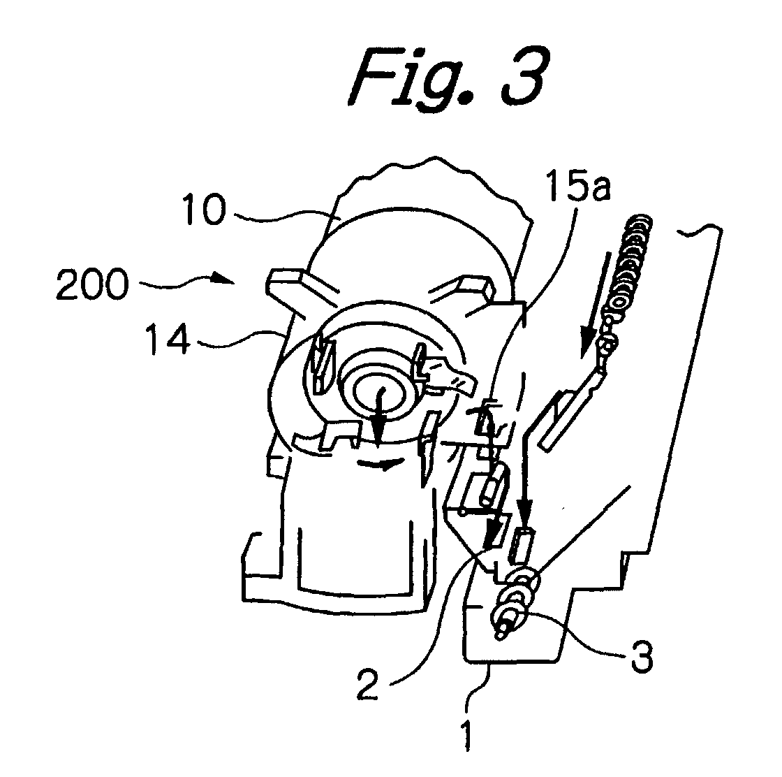
- a toner replenishing unit or device 200 embodying the present invention replenishes fresh toner to the developing unit 1 via a hole 2 formed in the casing of the developing unit 1.
- the toner replenishing unit 200 will be described in detail later.
- a first and a second screw 3 and 4 are disposed in the casing and convey the replenished toner toward the developing sleeve 5 while mixing it with magnetic carrier grains existing in the casing.
- the developing sleeve 5 accommodates magnets, not shown, therein.
- the magnets cause the carrier of the developer to form a magnet brush on the developing sleeve 5.
- the toner conveyed toward the developing sleeve 5 and charged by the screws 3 and 4 electrostatically deposit on the carrier.
- the developing sleeve 5 in rotation conveys the toner deposited on the magnet brush or carrier toward the drum 7.
- a doctor blade 6 regulates to the toner to a preselected thickness.
- the toner then deposits on the latent image formed on the drum 7 for thereby forming a toner image, as stated earlier.
- a toner sensor 8 is positioned beneath the first screw 3 for monitoring the toner content of the developer existing in the developing unit 1.
- the toner sensor 8 is implemented as, e.g., a magnetism sensor responsive to the permeability of the developer, which varies in accordance with the toner content of the developer 1.
- the toner sensor 8 outputs a signal representative of such a condition.
- a controller not shown, included in the copier body 100 sends a replenishment command to the toner replenishing unit 200.
- the toner replenishing unit 200 replenishes toner to the casing of the developing unit 1 via the hole 2. It is to be noted that the toner sensor 8 senses a toner end condition and a toner near-end condition as well.
- the toner replenishing unit 200 includes a casing 201 for storing a toner bottle 10 packed with fresh toner.
- the casing 201 is generally made up of an upper case or case cover 11, a lower case or case body 12, and a locking member or locking means 13.
- the lower case 12 plays the role of a case body for supporting the toner bottle 10 and is formed with an opening 12b for receiving the toner bottle 10.
- the upper case 11 is mounted to the lower case 12 for closing the opening 12b.
- the locking member 13 locks the upper case 11 mounted to the lower case 12 to the lower case 12.
- the toner bottle 10 is formed with a spiral groove 10a in its circumferential wall.
- the spiral groove 10a conveys the toner stored in the toner bottle 10 toward a mouth 10b.
- the toner is driven out of the toner bottle 10 via the mouth 10b.
- a cap 14 is removably fitted on the mouth 10b and received in the lower case 12 together with the toner bottle 10. More specifically, the cap 14 is received in a cap holder 15 formed integrally with the lower case 12.
- the cap holder 15 is formed with a toner outlet 15a.
- a toner guide member 16 is formed with a hole 16a and fitted on part of the cap holder 15 formed with the toner outlet 15a.
- a plurality of Mylar sheets 17 are fitted on the toner outlet end of the cap 14 and extend in the radial direction of the cap 14.
- a slider 18 is mounted on the toner guide member 16 for selectively opening or closing the hole 16a.
- a spring not shown, constantly biases the slider 18 such that the slider 18 tends to block the hole 16a. More specifically, when the toner replenishing unit 200 is mounted to the copier body 100, the slider 18 automatically moves to the position where it unblocks the hole 16a.
- the controller sends a replenishment command to the toner replenishing unit 200.
- a driveline not shown, arranged in the copier body 100 causes the toner bottle 10 to rotate.
- the driveline transfers rotation to the toner bottle 10 via a coupling that automatically couples when the toner replenishing unit 200 is mounted to the copier body 100.
- the spiral groove 10a conveys the toner in the bottle 10 to the mouth 10b.
- the toner is therefore delivered to the cap holder 15 via the mouth 10b, which is rotating integrally with the toner bottle 10.
- the Mylar sheets 17 fitted on the cap 14 scoop up the toner with the result that the toner is introduced in the toner guide member 16 via the toner outlet 15a. Consequently, the toner is replenished to the developing unit 1 via the hole 16a of the toner guide member 16 and the previously mentioned hole 2 formed in the casing of the developing unit 1.
- the upper case 11 is formed with a plurality of hooks 11a while the lower case 12 is formed with a plurality of lugs 12a.
- the hooks 11a mate with the lugs 12a by light snap fitting, connecting the upper case 11 to the lower case 12. Subsequently, the locking member 13 locks the upper case 11 to the lower case 12.
- the upper case 11 and lower case 12 are respectively formed with rail portions 22 and 23 extending in the lengthwise direction of the cases 11 and 12.
- the locking member 13 is formed with a parallel channel portions 13a and 13b such that the channel portions 13a and 13b extend in the lengthwise direction of the cases 11 and 12.
- the locking member 13 is slid onto the cases 11 and 12 from the end opposite to the toner replenishing end with the channel portions 13a and 13b respectively mating with the rail portions 22 and 23. In this condition, the locking member 13 surely locks the case 11 to the case 12.
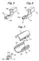
- the locking member 13 is formed with grooves 20 extending over the entire length of the member 13.
- the grooves 20 allow the locking member 13 to be easily broken.
- the grooves 20 therefore promote easy separation of the upper case 11 and lower case 12.
- a new locking member 13 is used to again lock the upper case 11 to the lower case 12. In this manner, the casing 201 can have the two cases 11 and 12 surely locked to each other and easily separated from each other.
- FIG. 6 shows another specific configuration of the locking member 13 that promotes easy disassembly of the casing 201.
- the locking member 13 includes a thin wall 21 extending over the entire length of the member 13. In the event of disassembly, the thin wall 21 also allows the locking member 13 to easily break thereat.
- the walls of the locking member 13 where the grooves 20 are formed or the thin wall 21 should preferably be 1 mm thick or below, more preferably 0.7 mm.
- the walls with the grooves 20 or the thin wall 21 should preferably be formed of hard, fragile resin, e.g., polystyrol. In any case, the grooves 20 or the thin wall 21 reduces a period of time necessary for recycling the toner replenishing unit 200.
- the rail portions 22 and 23 of the cases 11 and 12, respectively should preferably be sufficiently strong. Further, it is necessary to distinguish the recycled toner replenishing unit 200 from a new toner replenishing unit 200.
- the locking member 13 of a particular color should preferably be used for each of the recycled casing 201 and new casing 201. This kind of scheme facilitates the distinction.
- FIG. 8 shows the toner replenishing unit 200 in an assembled condition.
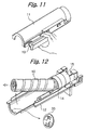
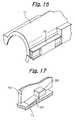
- FIGS. 9 through 17 for describing a procedure for disassembling the toner replenishing unit 200 for the recycling purpose.
- the locking member 13 is nipped by finger and then pushed in a direction perpendicular to the direction in which the locking member 13 is slid onto the case 201.
- the locking member 13 breaks off and causes the rail portions 23 of the lower case 12 to be released from the locking member 13.
- the used toner bottle 10 is picked up from the lower case 12 together with the cap 14.
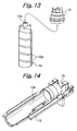
- a coupling 30 intervening between the driveline of the copier body 100 and the toner bottle 10 is also removed.
- the cap 14 is removed from the toner bottle 10.
- the cap 14 removed from the toner bottle 10 and the lower case 12 are cleaned to remove the toner deposited thereon (see FIG. 14).
- the locking member 13 and lower case 12 should preferably be formed with a catch 24 and a hole 25, respectively.
- the locking member 13 is mounted to the case 201 with the catch 24 mating with the hole 25. This prevents the locking member 13 from being easily released from the case 201 when subjected to a shock or an impact during transport.
- the locking member 13 may be locked to the upper case 11.
- the locking member 13 may be formed with a catch 24 and lugs 26 while the upper case 11 may be formed with a hole 25 and catches 27. In such a configuration, the catch 24 mates with the hole 25 while the lugs 26 engage with the catches 27. In this condition, the locking member 13 is locked to the upper case 11.
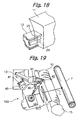
- the optical writing unit 103 is positioned below the toner replenishing unit 200, as shown in FIGS. 1 and 2.
- the writing unit 103 includes a shutter 40 pivotable about a shaft 41.
- the shutter 40 is usually positioned to block the optical path of the laser beam L, as shown in FIG. 19.
- An arm 42 is also mounted on the shaft 41 and extends to a path along which the toner replenishing unit 200 is mounted and dismounted from the copier body 100.
- the arm 42 is brought into contact with and caused to angularly move by the locking member 13 mounted on the casing 201. Therefore, only when the toner replenishing unit 200 is mounted to the copier body 100, the shutter 40 unblocks the optical path of the laser beam L.
- the illustrative embodiment has various unprecedented advantages, as enumerated below.
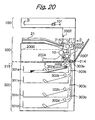
- FIG. 20 an image forming apparatus representative of an alternative embodiment of the present invention is shown and also implemented as a copier. It is to be noted that the reference numerals used in this embodiment are independent of the reference numerals used in the previous embodiment and therefore do not always designate identical reference numerals.
- the copier is generally made up of a scanner section 100 for reading a document, an image forming section 200 for forming an image on the sheet P, and a sheet feed section for feeding the sheet P to the image forming section 200.
- a controller not shown, controls the various sections of the copier.
- the image forming section 200 includes a laser writing unit 200A including a laser diode and a polygonal mirror although not shown specifically.
- the scanner reads a document laid on a glass platen, not shown, with an image sensor 101 and delivers image data to the controller.
- the controller controls a laser diode, a polygonal mirror and so forth included in the laser writing unit 200A in accordance with the image data.
- the laser diode scans a photoconductive drum 1, which is included in a process cartridge 200B, in accordance with the image data.
- a latent image corresponding to the document image is formed on the drum 1.
- the latent image is transformed to a toner image by development.
- the image forming section 200 additionally includes an image transferring device 200C, a fixing device 200D, a sheet discharging device 200E, doors 200F and 200G, and a toner replenishing device not shown.
- the door 200F is openable about a shaft 214 in a direction indicated by an arrow G.
- the door 200G is openable about a shaft 215 in the front-and-rear direction, i.e., the direction perpendicular to the sheet surface of FIG. 20.
- the sheet feed section 300 includes four sheet cassettes 301a, 301b, 301c and 301d, four pickup rollers 302a, 302b, 302c and 302d, and four roller pairs 303a, 303b, 303c and 303d.
- the sheet cassettes 301a through 301d each are loaded with a sheet stack P of particular size and movable into and out of the copier body in the front-and-rear direction with respect to FIG. 2.
- the pickup rollers 302a through 302d are respectively assigned to the sheet cassettes 301a through 301d, and each pays out the top sheet P from the associated sheet cassette.
- the sheet P is then conveyed via a sheet path on which the roller pairs 303a through 303d are arranged.
- the controller drives one of the pickup rollers 302a through 302d while effecting laser writing and development in accordance with the image data to thereby form a toner image on the drum 1.
- One of the pickup rollers 302a through 302d driven by the controller pays out the top sheet P from associated one of the sheet cassettes 301a through 301d.
- the sheet P is then conveyed to an image transfer position between the process cartridge 200B and the image transferring device 200 via one or more of the roller pairs 303a through 303d.
- the image transferring device 200 includes an image transfer roller, not shown, to which a bias is applied from bias applying means, not shown, at the time of image transfer.
- the image transfer roller is pressed against the drum 1, forming a nip for image transfer.
- the toner image formed on the drum 1 is brought into register with the sheet P entered the nip.
- the toner image is transferred from the drum 1 to the sheet 1 under the action of an electric field formed by the bias and nip pressure acting between the drum 1 and the image transfer roller.
- the sheet P with the toner image is conveyed to the fixing unit 200D.
- the fixing unit 200D fixes the toner image on the sheet P with heat and pressure.
- the sheet P coming out of the fixing unit 200D is driven out of the copier body via an outlet roller pair included in the sheet discharging device 200.
- a developing unit included in the process cartridge 200B will be described specifically with reference to FIG. 21.
- toner is replenished into the developing unit via a hole A.
- a first and a second screw 4 and 5 convey the replenished toner toward a developing sleeve 2 while mixing it with magnetic carrier grains existing in the developing unit.
- the developing sleeve 2 accommodates magnets, not shown, therein.
- the magnets cause the carrier of the developer to form a magnet brush on the developing sleeve 2.
- the toner conveyed toward the developing sleeve 2 and charged by the screws 4 and 5 electrostatically deposits on the carrier.
- the developing sleeve 2 in rotation conveys the toner deposited on the magnet brush or carrier toward the drum 1.
- a doctor blade 3 regulates the toner to a preselected thickness.
- the toner then deposits on the latent image formed on the drum 1 for thereby forming a toner image.
- a toner sensor 6 is positioned beneath the first screw 4 for monitoring the toner content of the developer existing in the developing unit.
- the toner sensor 6 outputs a signal representative of such a condition.
- the controller outputs a replenishment command and thereby causes a toner bottle or toner container 10 (see FIG. 20) to rotate.
- toner is replenished from the toner bottle 10 to the developing unit via the hole A.
- the toner sensor 6 senses a toner end condition and a toner near-end condition as well.
- a toner replenishing unit or device characterizing the illustrative embodiment will be described in detail with reference to FIGS. 21 through 23.
- the controller sends a replenishment command to the toner replenishing unit.
- the toner replenishing unit rotates the toner bottle 10.
- a spiral screw formed in the circumferential wall of the toner bottle 10 drives the toner in the bottle 10 out of the bottle 10.
- a cap 11 is rotated integrally with the toner bottle 10.
- Mylar sheets 7 (see FIG. 22) fitted on the cap 11 scoop up the toner to a toner outlet 13.
- the toner is therefore replenished to the developing unit via the toner outlet 13 and a toner guide member 14.
- a shutter is mounted on the toner guide member 14 and selectively opened or closed when the toner replenishing unit is mounted to or dismounted from, respectively, the copier body.
- the toner replenishing unit additionally includes an upper case 9, a lower case 8, a locking member 12, and a relay plate 15.
- the toner bottle 10, upper case 9 and relay plate 15 are set on the lower case 8, as shown in FIG. 23.
- the locking member 12 is mounted to the upper case 9 and lower case 8 to thereby lock them to each other.
- a driven portion included in the relay plate 15 is exposed to the outside of the cases 8 and 9, which constitute the casing of the toner replenishing unit in combination.
- the lower case 8 and upper case 9 encase the toner bottle 10, as stated above. Therefore, even when the major component of the toner bottle 10 is PET lower in mechanical strength than PE, the two cases 8 and 9 protect the bottle 10 from, e.g., the tip of a screwdriver; otherwise, a hole would be formed in the bottle 10 and cause the toner to leak. In addition, the cases 8 and 9 protect the toner bottle from deformation during transport. Moreover, PET is lower in cost than PE.
- the illustrative embodiment sets up a relation of D1 ⁇ D2.
- the relay plate 15 is therefore positioned inside the toner bottle 10 when engaged with the bottle 10, as seen in the axial direction of the bottle 10. It follows that during drive transmission the circumference of the relay plate 15 does not slide on the lower case 8 or the upper case 9, preventing a load torque from increasing.
- the difference between the diameter D1 and the outside diameter D2 should preferably be 1.0 mm or above.
- the copier body imparts rotation to the toner bottle 10 via the relay plate 15 in the axial direction of the bottle 10.
- FIGS. 24A and 24B show a relation between the toner bottle 10, the relay plate 15, and a drive shaft 16.
- the drive shaft 16 includes a cam-like projection 15 that mates with a recess, or previously mentioned driven portion, included in the relay plate 15.
- the relay plate 15 additionally includes a cam-like projection or drive portion that mates with a recess formed in the toner bottle 10. Even if such portions of the drive shaft 16, relay plate 15 and toner bottle 10 are not accurately engaged with each other, accurate engagement can be set up on the rotation of the drive shaft 16.
- a torque is transmitted from the drive shaft 16 to the toner bottle 10 via the relay plate 15.
- the illustrative embodiment therefore allows the toner bottle 10 to rotate about an axis that substantially does not move, compared to a conventional gear scheme that transfers rotation to the circumference of a toner bottle. This frees the toner bottle 10 from oscillation. Further, the relay plate 15 between the drive shaft 16 and the toner bottle 10 reduces the oscillation of the shaft 16 to thereby further reduce the oscillation of the bottle 10. The illustrative embodiment therefore insures stable toner replenishment from the toner bottle 10 to the developing unit.
- the relay plate 15 moves in the direction perpendicular to the axes of the shaft 16 and toner bottle 10 and plays the role of a free joint. It follows that the rotation of the drive shaft 16 can be smoothly transferred to the toner bottle 10, protecting the bottle 10 from damage.
- a plurality of relay plates 15 each having a particular width in the axial direction may be prepared beforehand.
- a relay plate 15 whose thickness matches with the axial length (capacity) of the toner bottle 10 can be used to insure the smooth transfer of drive transfer.
- a plurality of relay plates 15 of different colors maybe prepared in order to indicate how many times the toner bottle 10 is recycled. For example, a white relay plate 15 may be fitted on the toner bottle 10 when it is new, a blue replay plate 15 may be attached to the bottle 10 when it is recycled one time, or a yellow relay plate 15 may be fitted on the bottle 10 when it is recycled two times.
- the illustrative embodiment achieves the following advantages (1) through (3).
- the locking means is configured to allow a locking of a releasable connection or locking between the upper case and lower case in particular such that the locking or connection cannot be released.
- the upper case is connectable by the releasable connection or the releasable locking with the lower case and/or vice versa.
- this releasable locking or connection is performed by actuating or operating at least one of the upper case and the lower case.
- the upper case and the lower case comprise engaging members in order to allow for the releasable locking or connection.
- the engaging members are integral with the upper case and the lower case, respectively.
- the upper case and the lower case and/or the engaging members are configured such that a locking is achieved if the upper case and/or the lower case is operated or actuated in a predetermined direction.
- the locking means is configured to fix or secure or lock the aforementioned releasable locking or connection or link of the upper case and the lower case such that a release of the locking or connection or link is blocked by the locking means.
- this blocking may be made undone by actuating or operating the locking means.
- this is performed by actuating or operating the locking means in a predetermined direction.
- this predetermined direction is at a predetermined angle to the predetermined direction of actuating and operating the upper and/or lower case for connecting or locking the upper case and lower case.
- this angle is 90° or in a range of 45° to 125° or close to 90° in order to decouple the movement of the releasable locking by means of the upper case and lower case or engaging members and the movement of the locking by means of the locking means.
- the locking means is preferably configured to unblock the releasable connection or locking between the upper case and the lower case.
- the locking means is provided for this purpose with a predetermined breaking and/or deforming portion, point or region.
- this predetermined portion, point or region allows for a more easy braking or deforming as in remainder portions of the locking means.
- this braking or deforming is at best achievable, if a force or pressure is applied in a predetermined direction which is at an angle to the direction of movement for locking the releasable locking or connection.
- this angle is 90° or around 90° or at least in a range between 45° and 125°.
- the locking or connection between the upper case and the lower case is a releasable formfit and/or snap connection.
- both the upper case and the lower case extent parallel to the longitudinal axis of the casing and/or a toner container.
- the present invention is also directed to a casing which includes a toner container.
- the line of transition between the upper case and the lower case extends at least approximately parallel to the longitudinal axis of the casing and/or toner container.
- the lower case represents one part of the casing and the upper case represents another part of the casing.
- the terms "lower” and "upper” in particular refer to the location of the cases in case of mounting the case in an image forming apparatus.
- a casing is mounted horizontally, i.e. the axis of the casing extends in the horizontal direction, at least approximately.
- the casing comprises a relaying member which relays a driving force external to the casing to a toner container in the casing.
- this relay member has a diameter which is somewhat smaller than the diameter of the casing, at least in the case the casing has a cylindrical shape.
- the casing is configured such that the relay member or relay plate cannot fall out of or leave the casing, in particular cannot leave the casing in case the upper case and the lower case are connected or locked together.
- the relay member is constituted such that it represents a part of a gearing which is used for driving a toner bottle into rotation by applying a rotational force to the relay member.
- the relay member is constituted such that there is a clearance which allows an offset between the driven axis of the relay member and the drive axis of the relay member. In other words, preferably, there is an axial play of shaft and/or an internal slackness provided by means of the relay member.
- the locking member in particular the undeformed and/or unbroken locking member is configured to unblock an operation of the toner replenishing means and/or image forming apparatus by properly mounting the casing in the toner replenishing device or the image forming apparatus and in particular by contacting or interacting engaging the locking member with an unblocking mechanism or unblocking device (e.g. comprising a locking member position sensor for sensing proper position and/or shape of the locking member and a controller for unblocking the image forming apparatus) during the mounting operation and/or when properly mounted.
- an unblocking mechanism or unblocking device e.g. comprising a locking member position sensor for sensing proper position and/or shape of the locking member and a controller for unblocking the image forming apparatus
- portions or elements engaging or mating with the locking member are provided in the toner replenishing device or image forming apparatus in order to achieve an unblocking of a formerly blocked image forming operation and/or toner replenishing operation.
- the blocking of a laser beam is unblocked and/or the blocking of a toner replenishment opening is unblocked by providing an unblocking mechanism which interacts with the locking means or locking member when mounted to the toner replenishing device.
- this unblocking is only performed in case the locking means or locking member is unbroken or undeformed, i.e. is in proper shape.
Landscapes
- Physics & Mathematics (AREA)
- General Physics & Mathematics (AREA)
- Life Sciences & Earth Sciences (AREA)
- Sustainable Development (AREA)
- Dry Development In Electrophotography (AREA)
Abstract
Description
Claims (32)
- A casing for accommodating a toner container, comprising:wherein said locking means is configured to loose a function of locking said upper case to said lower case when unlocking said upper case from said lower case and/or is configured to allow a locking of a releasable connection a locking between the upper case and lower case.a lower case formed with an opening for receiving the toner container;an upper case configured to be mounted to said lower case to thereby cover said opening of said lower case; andlocking means for locking said upper case closing said opening to said lower case;
- The casing as claimed in claim 1, wherein said locking means unlocks said upper case from said lower case or allows an unlocking of said releasable connection or locking when permanently deformed and/or when broken to a shape unable to lock said upper case to said lower case or unable to lock said releasable connection or locking, respectively.
- The casing as claimed in claim 1 or 2, wherein said upper case and said lower case comprise respective members separate from each other, and
said locking means is positioned on said upper case or said lower case. - The casing as claimed in one of claims 1 to 3, wherein said locking means comprises a locking member separate from said upper case and said lower case.
- The casing as claimed in one of claims 1 to 4, wherein said upper case and said lower case include respective engaging portions that face each other when said upper case closes said opening of said lower case, and
said locking member includes engaging portions configured to engage with said engaging portions of said upper case and/or said lower case to thereby lock said upper case to said lower case. - The casing as claimed in one of claims 1 to 5, wherein said locking member is configured to conceal, when locking said upper case to said lower case, said engaging portions of said upper case and said lower case.
- The casing as claimed in one of claims 1 to 6, wherein said lower case includes a toner outlet for delivering toner stored in said toner container, and
said engaging portions of said upper case and said lower case are remote from said toner outlet. - The casing as claimed in claim 7, wherein said engaging portions of said upper case and said lower case face in parallel to each other when said upper case closes said opening of said lower case,
said engaging portions of said locking member are slid onto said engaging portions of said upper case and said lower case from one end in a preselected direction to thereby lock said upper case to said lower case, and
said locking member includes a catch for preventing, after said engaging portions of said locking member have engaged with said engaging portions of said upper case and said lower case, said engaging portions of said upper case and said lower case from being slid in a direction opposite said preselected direction. - A casing for accommodating a toner container, in particular as claimed in one of claims 1 to 8, comprising:wherein said upper case and said lower case have respective engaging portions for causing said upper case to engage with said lower case and engaging portions for causing said locking member to engage with said upper case and said lower case; anda lower case formed with an opening for receiving the toner container;an upper case configured to be mounted on said lower case to thereby cover said opening of said lower case; anda locking member for locking said upper case closing said opening to said lower case;
a direction in which said upper case is brought into engagement with said lower case and a direction in which said locking member is brought into engagement with said upper case and said lower case are perpendicular to each other. - A casing for accommodating a toner container in particular as claimed in one of claims 1 to 9, comprising:wherein said locking member looses a function of locking said upper case to said lower case when subjected to a pressure in a direction perpendicular to a direction in which said locking member is brought into engagement with an engaging portion of said lower case .a lower case formed with an opening for receiving the toner container;an upper case for covering said opening of said lower case; anda locking member for locking said upper case closing said opening to said lower case;
- The casing as claimed in claim 10, wherein said locking member has a strength that allows said locking member to be broken at least into two at a position between a portion engageable with said engaging portion of said lower case and a portion engageable with an engaging portion of said upper case when subjected to the force or the pressure.
- The casing as claimed in claim 10 or 11, wherein said locking member has a wall thickness smaller at a portion breakable when subjected to the force or the pressure than the other portion.
- The casing as claimed in claim 12, wherein the wall thickness of said portion breakable is 1 mm or less.
- The casing as claimed in one of claims 11 to 13, wherein at least said portion breakable is formed of polystyrol.
- The casing as claimed in claim, wherein said portion breakable comprises a groove extending along said portions of said locking member.
- A locking member, in particular for a casing in accordance with claims 1 to 15, for locking an upper case configured to close an opening formed in a lower case for receiving a toner container to said lower case, said locking member is configured to loose a function of locking said upper case to said lower case when unlocking said upper case from said lower case.
- A locking member, in particular for a casing in accordance with claims 1 to 15, for locking an upper case configured to close an opening formed in a lower case for receiving a toner container to said lower case, said locking member is configured to loose a function of locking said upper case to said lower case when subjected to a pressure in a direction perpendicular to a direction in which said locking member is brought into engagement with an engaging portion of said lower case.
- The locking member as claimed in claim 16 or 17, wherein said locking means unlocks said upper case from said lower case when permanently deformed and/or when broken to a shape unable to lock said upper case to said lower case.
- A toner replenishing device for replenishing toner to a developing device for developing a latent image formed on an image carrier, said toner replenishing device comprising:the casing of one of claims 1 to 15; andtoner replenishing means for replenishing the toner discharged from the toner container to the developing device.
- The device as claimed in claim 19, wherein said toner replenishing means is constructed integrally with said lower case.
- A method of recycling a toner replenishing device comprising:a casing in particular in accordance with one of claims 1 to 15 comprising a lower case formed with an opening for receiving a toner container, an upper case for covering said opening of said lower case and locking means for locking said upper case closing said opening to said lower case; andtoner replenishing means for replenishing toner discharged from the toner container to a developing device to thereby develop a latent image formed on an image carrier;said method replacing the toner container run out of toner with a new toner container by comprising:an unlocking step of unlocking said upper case and said lower case locked to each other by said locking means;a removing step of removing said upper case from said lower case and removing the toner container from said lower case via said opening uncovered; anda setting step of setting the new toner container in said lower case; anda locking step of locking said new toner container to said lower case by using a new locking means exclusive for recycling.
- The method as claimed in claim 21, wherein said locking means for recycling comprises a locking member different in color from a locking member fitted on the toner container replaced with the new toner container.
- An image forming apparatus comprising:an image carrier configured to form a toner image thereon;latent image forming means for forming a latent image on said image carrier;developing means for developing the latent image; andthe toner replenishing device in accordance with one of claims 19, 20, 26 to 32 for replenishing toner to said developing means for developing the latent image.
- The apparatus as claimed in claim 23, wherein said toner replenishing device is removably mounted to a body of said apparatus and further comprises a hole for replenishing the toner to said developing means with said toner replenishing means and a slider for selecting blocking or unblocking said hole, and
said body of said apparatus includes moving means for moving, when said toner replenishing device is mounted to said body, said slider to an unblocking position or moving, when said toner replenishing device is dismounted from said body, said slider to a blocking position. - The apparatus as claimed in claim 23 or 24, further comprising:wherein said locking means moves said shutter to an unblocking position when said toner replenishing device is mounted to said body of said apparatus or moves said shutter to a blocking position when said toner replenishing device is dismounted from said body.latent image writing means for writing the latent image on said image carrier with a light beam; anda shutter for selectively blocking an optical path of the light beam to issue from said latent image writing means;
- A toner replenishing device in accordance with claim 19 or 20,
said toner container comprises a screw type toner bottle that is rotated, when said toner replenishing device is mounted to a body of an image forming apparatus, by rotation transferred from said body to thereby discharge the toner to said toner replenishing means. - A toner replenishing device in particular in accordance with claim 19 or 20, for replenishing toner to a developing section including an image forming apparatus, said toner replenishing device comprising:a toner container storing the toner and rotatable to discharge said toner via a mouth thereof; anda relay member including a driven portion for receiving rotation from a drive source and a drive portion engaged with said toner container in an axial direction of said toner container to thereby transfer said rotation to said toner container.
- The device as claimed in claim 27, further comprising a casing configure to accommodate said toner container
- The device as claimed in claim 27 or 28, wherein said relay member and said toner container are substantially circular and substantially cylindrical, respectively, and
assuming that said relay member and said toner container have a diameter D1 and an outside diameter D2, respectively, a relation of D1 < D2 holds. - The device as claimed in one of claims 27 to 29, wherein when said toner container is reused, said relay member is replaced with a relay member different in color from said relay member.
- The device as claimed in one of claims 27 to 30, wherein said toner container is mainly formed of polyethylene terephthalate.
- The device as claimed in one of claims 27 to 31, wherein said toner container and said relay member are movable relative to each other in a direction perpendicular to an axis of rotation of said toner container.
Applications Claiming Priority (8)
| Application Number | Priority Date | Filing Date | Title |
|---|---|---|---|
| JP2000391984 | 2000-12-25 | ||
| JP2000391984 | 2000-12-25 | ||
| JP2001084554 | 2001-03-23 | ||
| JP2001084554 | 2001-03-23 | ||
| JP2001307850A JP2002258595A (en) | 2000-12-25 | 2001-10-03 | Image forming apparatus, developer supply device, developer supply device regenerating method, developer container storage housing, developer container storage method, locking member |
| JP2001307850 | 2001-10-03 | ||
| JP2001315096A JP2002351205A (en) | 2001-03-23 | 2001-10-12 | Toner supply device and image forming apparatus using the same |
| JP2001315096 | 2001-10-12 |
Publications (3)
| Publication Number | Publication Date |
|---|---|
| EP1220050A2 true EP1220050A2 (en) | 2002-07-03 |
| EP1220050A3 EP1220050A3 (en) | 2003-01-02 |
| EP1220050B1 EP1220050B1 (en) | 2010-01-20 |
Family
ID=27481909
Family Applications (1)
| Application Number | Title | Priority Date | Filing Date |
|---|---|---|---|
| EP20010130525 Expired - Lifetime EP1220050B1 (en) | 2000-12-25 | 2001-12-21 | Toner replenishing device and image forming apparatus using the same |
Country Status (4)
| Country | Link |
|---|---|
| EP (1) | EP1220050B1 (en) |
| CN (2) | CN1241073C (en) |
| DE (1) | DE60141113D1 (en) |
| TW (1) | TWI269946B (en) |
Cited By (3)
| Publication number | Priority date | Publication date | Assignee | Title |
|---|---|---|---|---|
| US7734232B2 (en) | 2007-02-21 | 2010-06-08 | Murata Machinery Ltd. | Toner cartridge |
| US8131188B2 (en) | 2007-03-28 | 2012-03-06 | Brother Kogyo Kabushiki Kaisha | Developer container |
| US11982952B2 (en) | 2019-09-17 | 2024-05-14 | Canon Kabushiki Kaisha | Toner cartridge having feeding member and pump for discharging pump |
Families Citing this family (9)
| Publication number | Priority date | Publication date | Assignee | Title |
|---|---|---|---|---|
| US6980755B2 (en) * | 2002-09-30 | 2005-12-27 | Canon Kabushiki Kaisha | Recycling method for developer supplying unit including the step of driving a feeding member in a direction to feed developer from a developer supply port to a developer accommodating portion |
| JP2006030488A (en) * | 2004-07-14 | 2006-02-02 | Ricoh Co Ltd | Toner bottle and image forming apparatus |
| JP4589045B2 (en) * | 2004-07-15 | 2010-12-01 | 株式会社東芝 | Toner container |
| JP2006030574A (en) * | 2004-07-15 | 2006-02-02 | Toshiba Corp | Toner cartridge and detaching mechanism thereof |
| JP4587777B2 (en) * | 2004-10-29 | 2010-11-24 | 京セラミタ株式会社 | Image forming apparatus |
| CN101295153B (en) * | 2008-06-25 | 2010-06-02 | 殷宗明 | A split-type toner cartridge capable of cyclically replacing the toner cartridge |
| JP5487934B2 (en) * | 2009-12-15 | 2014-05-14 | 富士ゼロックス株式会社 | Toner cartridge and image forming apparatus using the same |
| CN111108445A (en) | 2017-10-05 | 2020-05-05 | 惠普发展公司,有限责任合伙企业 | Container and cap for printing material |
| CN110116863B (en) * | 2019-03-14 | 2024-04-12 | 南京工程学院 | Can supply push type toothpaste |
Family Cites Families (8)
| Publication number | Priority date | Publication date | Assignee | Title |
|---|---|---|---|---|
| JPH02287577A (en) * | 1989-04-28 | 1990-11-27 | Ricoh Co Ltd | electrophotographic equipment |
| JP3904246B2 (en) * | 1994-04-08 | 2007-04-11 | 株式会社リコー | Toner supply device and developing device |
| KR100227914B1 (en) * | 1995-10-11 | 1999-11-01 | 이토가 미찌야 | Image forming apparatus and toner supplying apparatus, and toner container mounted thereon |
| JP3527384B2 (en) * | 1996-06-10 | 2004-05-17 | 株式会社リコー | Toner container |
| US5937238A (en) * | 1996-12-04 | 1999-08-10 | Nashua Corporation | Slotted clip for use in the reassembly of printer toner cartridges |
| US5946520A (en) * | 1997-06-02 | 1999-08-31 | Hewlett-Packard Company | Anti-fraud pull tab system for printing products |
| JPH1115265A (en) * | 1997-06-20 | 1999-01-22 | Ricoh Co Ltd | Image forming device |
| US5907747A (en) * | 1998-02-02 | 1999-05-25 | Ward Sealing, Inc. | Prefilled, presealed toner cartridge insert |
-
2001
- 2001-12-21 EP EP20010130525 patent/EP1220050B1/en not_active Expired - Lifetime
- 2001-12-21 TW TW90131888A patent/TWI269946B/en not_active IP Right Cessation
- 2001-12-21 DE DE60141113T patent/DE60141113D1/en not_active Expired - Lifetime
- 2001-12-25 CN CN 01138196 patent/CN1241073C/en not_active Expired - Fee Related
- 2001-12-25 CN CNB2004100558211A patent/CN100390676C/en not_active Expired - Fee Related
Cited By (4)
| Publication number | Priority date | Publication date | Assignee | Title |
|---|---|---|---|---|
| US7734232B2 (en) | 2007-02-21 | 2010-06-08 | Murata Machinery Ltd. | Toner cartridge |
| US8131188B2 (en) | 2007-03-28 | 2012-03-06 | Brother Kogyo Kabushiki Kaisha | Developer container |
| US11982952B2 (en) | 2019-09-17 | 2024-05-14 | Canon Kabushiki Kaisha | Toner cartridge having feeding member and pump for discharging pump |
| US12461468B2 (en) | 2019-09-17 | 2025-11-04 | Canon Kabushiki Kaisha | Toner cartridge having feeding member and pump for discharging toner |
Also Published As
| Publication number | Publication date |
|---|---|
| CN100390676C (en) | 2008-05-28 |
| CN1241073C (en) | 2006-02-08 |
| TWI269946B (en) | 2007-01-01 |
| EP1220050B1 (en) | 2010-01-20 |
| DE60141113D1 (en) | 2010-03-11 |
| CN1365030A (en) | 2002-08-21 |
| EP1220050A3 (en) | 2003-01-02 |
| CN1567100A (en) | 2005-01-19 |
Similar Documents
| Publication | Publication Date | Title |
|---|---|---|
| TWI862075B (en) | Cartridge | |
| KR100747728B1 (en) | Developer container, developer supplying device, and image forming apparatus | |
| JP4412421B1 (en) | Developer container and image forming apparatus | |
| US7738817B2 (en) | Developer supply container and image forming apparatus | |
| TWI403866B (en) | Process cartridge, developer supply cartridge and electrophotographic image forming apparatus | |
| US6993273B2 (en) | Developer supply container, and coupling-driving member for developer supply container | |
| JP5691391B2 (en) | Image forming apparatus | |
| KR20100070365A (en) | Toner container and image forming apparatus | |
| JP2006323082A (en) | Developer supply container | |
| EP1220050B1 (en) | Toner replenishing device and image forming apparatus using the same | |
| CN100573358C (en) | Developer supply container and developer supply system | |
| EP0823674A1 (en) | Powder storing container, developing agent cartridge, developing agent replenishing apparatus | |
| JP4476617B2 (en) | Image forming apparatus and process cartridge | |
| CN102455623B (en) | Attached dismounting body and image processing system | |
| US5432592A (en) | Developer cartridge and image forming apparatus using the same | |
| CN101017349A (en) | Image forming unit, rotary type developing unit, and toner replenishment container | |
| US5970291A (en) | Self unlocking feature for toner container shutter | |
| JP3654788B2 (en) | Image forming apparatus | |
| CN1754132B (en) | Developer container, developer supply device and image forming device | |
| US20250278057A1 (en) | Image forming apparatus | |
| JP3904176B2 (en) | Electrophotographic image forming apparatus | |
| KR100826001B1 (en) | Developer container for image forming apparatus | |
| JP2002351202A (en) | Toner container | |
| JPH02146558A (en) | Picture forming device | |
| HK1139471A (en) | Developer container, developer supplying device, and image forming apparatus |
Legal Events
| Date | Code | Title | Description |
|---|---|---|---|
| PUAI | Public reference made under article 153(3) epc to a published international application that has entered the european phase |
Free format text: ORIGINAL CODE: 0009012 |
|
| 17P | Request for examination filed |
Effective date: 20011221 |
|
| AK | Designated contracting states |
Kind code of ref document: A2 Designated state(s): AT BE CH CY DE DK ES FI FR GB GR IE IT LI LU MC NL PT SE TR |
|
| AX | Request for extension of the european patent |
Free format text: AL;LT;LV;MK;RO;SI |
|
| PUAL | Search report despatched |
Free format text: ORIGINAL CODE: 0009013 |
|
| AK | Designated contracting states |
Kind code of ref document: A3 Designated state(s): AT BE CH CY DE DK ES FI FR GB GR IE IT LI LU MC NL PT SE TR |
|
| AX | Request for extension of the european patent |
Free format text: AL;LT;LV;MK;RO;SI |
|
| AKX | Designation fees paid |
Designated state(s): DE FR GB |
|
| 17Q | First examination report despatched |
Effective date: 20060630 |
|
| GRAP | Despatch of communication of intention to grant a patent |
Free format text: ORIGINAL CODE: EPIDOSNIGR1 |
|
| GRAS | Grant fee paid |
Free format text: ORIGINAL CODE: EPIDOSNIGR3 |
|
| GRAA | (expected) grant |
Free format text: ORIGINAL CODE: 0009210 |
|
| AK | Designated contracting states |
Kind code of ref document: B1 Designated state(s): DE FR GB |
|
| REG | Reference to a national code |
Ref country code: GB Ref legal event code: FG4D |
|
| REF | Corresponds to: |
Ref document number: 60141113 Country of ref document: DE Date of ref document: 20100311 Kind code of ref document: P |
|
| PLBE | No opposition filed within time limit |
Free format text: ORIGINAL CODE: 0009261 |
|
| STAA | Information on the status of an ep patent application or granted ep patent |
Free format text: STATUS: NO OPPOSITION FILED WITHIN TIME LIMIT |
|
| 26N | No opposition filed |
Effective date: 20101021 |
|
| REG | Reference to a national code |
Ref country code: FR Ref legal event code: PLFP Year of fee payment: 15 |
|
| REG | Reference to a national code |
Ref country code: FR Ref legal event code: PLFP Year of fee payment: 16 |
|
| PGFP | Annual fee paid to national office [announced via postgrant information from national office to epo] |
Ref country code: GB Payment date: 20161222 Year of fee payment: 16 Ref country code: DE Payment date: 20161213 Year of fee payment: 16 |
|
| PGFP | Annual fee paid to national office [announced via postgrant information from national office to epo] |
Ref country code: FR Payment date: 20161222 Year of fee payment: 16 |
|
| REG | Reference to a national code |
Ref country code: DE Ref legal event code: R119 Ref document number: 60141113 Country of ref document: DE |
|
| GBPC | Gb: european patent ceased through non-payment of renewal fee |
Effective date: 20171221 |
|
| REG | Reference to a national code |
Ref country code: FR Ref legal event code: ST Effective date: 20180831 |
|
| PG25 | Lapsed in a contracting state [announced via postgrant information from national office to epo] |
Ref country code: DE Free format text: LAPSE BECAUSE OF NON-PAYMENT OF DUE FEES Effective date: 20180703 Ref country code: FR Free format text: LAPSE BECAUSE OF NON-PAYMENT OF DUE FEES Effective date: 20180102 |
|
| PG25 | Lapsed in a contracting state [announced via postgrant information from national office to epo] |
Ref country code: GB Free format text: LAPSE BECAUSE OF NON-PAYMENT OF DUE FEES Effective date: 20171221 |