EP1220001A1 - Zoom lens and photographing system - Google Patents
Zoom lens and photographing system Download PDFInfo
- Publication number
- EP1220001A1 EP1220001A1 EP01310870A EP01310870A EP1220001A1 EP 1220001 A1 EP1220001 A1 EP 1220001A1 EP 01310870 A EP01310870 A EP 01310870A EP 01310870 A EP01310870 A EP 01310870A EP 1220001 A1 EP1220001 A1 EP 1220001A1
- Authority
- EP
- European Patent Office
- Prior art keywords
- unit
- wobbling
- magnification changing
- lens
- changing optical
- Prior art date
- Legal status (The legal status is an assumption and is not a legal conclusion. Google has not performed a legal analysis and makes no representation as to the accuracy of the status listed.)
- Granted
Links
- 230000003287 optical effect Effects 0.000 claims abstract description 110
- 238000003384 imaging method Methods 0.000 claims abstract description 44
- 238000003780 insertion Methods 0.000 claims description 92
- 230000037431 insertion Effects 0.000 claims description 92
- 239000004606 Fillers/Extenders Substances 0.000 description 81
- 230000004075 alteration Effects 0.000 description 27
- 238000010586 diagram Methods 0.000 description 27
- 230000014509 gene expression Effects 0.000 description 14
- 238000000034 method Methods 0.000 description 4
- 230000006866 deterioration Effects 0.000 description 3
- 239000011521 glass Substances 0.000 description 3
- 230000035945 sensitivity Effects 0.000 description 2
- 238000000926 separation method Methods 0.000 description 2
- 238000013459 approach Methods 0.000 description 1
- 230000003247 decreasing effect Effects 0.000 description 1
- 238000013461 design Methods 0.000 description 1
- 238000001514 detection method Methods 0.000 description 1
- CNQCVBJFEGMYDW-UHFFFAOYSA-N lawrencium atom Chemical compound [Lr] CNQCVBJFEGMYDW-UHFFFAOYSA-N 0.000 description 1
- 238000005259 measurement Methods 0.000 description 1
- 230000000007 visual effect Effects 0.000 description 1
Images





Classifications
-
- G—PHYSICS
- G02—OPTICS
- G02B—OPTICAL ELEMENTS, SYSTEMS OR APPARATUS
- G02B15/00—Optical objectives with means for varying the magnification
- G02B15/02—Optical objectives with means for varying the magnification by changing, adding, or subtracting a part of the objective, e.g. convertible objective
- G02B15/10—Optical objectives with means for varying the magnification by changing, adding, or subtracting a part of the objective, e.g. convertible objective by adding a part, e.g. close-up attachment
-
- G—PHYSICS
- G02—OPTICS
- G02B—OPTICAL ELEMENTS, SYSTEMS OR APPARATUS
- G02B15/00—Optical objectives with means for varying the magnification
- G02B15/14—Optical objectives with means for varying the magnification by axial movement of one or more lenses or groups of lenses relative to the image plane for continuously varying the equivalent focal length of the objective
- G02B15/144—Optical objectives with means for varying the magnification by axial movement of one or more lenses or groups of lenses relative to the image plane for continuously varying the equivalent focal length of the objective having four groups only
- G02B15/1441—Optical objectives with means for varying the magnification by axial movement of one or more lenses or groups of lenses relative to the image plane for continuously varying the equivalent focal length of the objective having four groups only the first group being positive
-
- G—PHYSICS
- G02—OPTICS
- G02B—OPTICAL ELEMENTS, SYSTEMS OR APPARATUS
- G02B27/00—Optical systems or apparatus not provided for by any of the groups G02B1/00 - G02B26/00, G02B30/00
- G02B27/64—Imaging systems using optical elements for stabilisation of the lateral and angular position of the image
- G02B27/646—Imaging systems using optical elements for stabilisation of the lateral and angular position of the image compensating for small deviations, e.g. due to vibration or shake
Definitions
- the present invention relates to a zoom lens suitable for a TV camera, video camera, and the like.
- AF autofocus
- a system called “hill-climbing AF” which obtains the distance to a principal object and drives a focus unit to an appropriate position is widely used.
- the direction of the best imaging position is detected from a change in a video signal by using some of the lens units of an image pickup system for imaging, and the extension direction of a focusing lens is calculated.
- a merit of this system is that no optical system need be newly used for distance measurement.
- a partial optical system of the image pickup system is slightly amplitude-driven (to be referred to as wobbled hereinafter) in the optical axis direction.
- a focus unit is driven to set the best focus on the image pickup surface on the basis of the detected signal.
- Japanese Patent No. 2744336 As a method of reducing a change in imaging magnification, the method disclosed in Japanese Patent No. 2744336 is available. This method is associated with a rear focus zoom lens which has the first unit having a positive refractive power, the second unit having a negative refractive power for magnification changing operation, the third unit having a positive refractive power, and the fourth unit having a positive refractive power and serving to correct an image plane fluctuation with a change in magnification, and is designed to perform focusing by using the fourth unit.
- a change in imaging magnification accompanying wobbling can be expressed by a paraxial trace.
- Several conditions for suppressing a change in imaging magnification accompanying wobbling small are described in USP 5,138,492.
- the conditions described in the above reference are effective for a method of reducing a change in imaging magnification in a state where an optical arrangement behind the stop is fixed, but are not sufficient to be applied to a case wherein the arrangement of an optical system is changed upon insertion/removal of an extender or the like and the incident angle of an off-axis principal ray on a wobbling lens unit, in particular, changes.
- a wobbling unit which can be slightly amplitude-driven in an optical axis direction to detect a best imaging position is placed closer to an image side than an insertion position of the magnification changing optical unit.
- the zoom lens sequentially includes, from an object side, a first unit which is fixed in magnification changing operation and has a positive refractive power, a second unit which moves in the optical axis direction in magnification changing operation and has a negative refractive power, a third unit for correcting an image plane fluctuation accompanying magnification changing operation, and a fourth unit having a positive refractive power for imaging, and a magnification changing optical unit which changes the overall focal length of the zoom lens can be inserted/removed in/from the fourth unit.
- a wobbling unit which can be slightly amplitude-driven in the optical axis direction to detect a best imaging position is placed closer to the image side than the insertion position of the magnification changing optical unit, and a stop for adjustment of light amount is preferably disposed at the object side with respect to the fourth unit.
- ⁇ 1 is an angle of an off-axis sub-principal ray incident on an object-side principal plane of the wobbling unit (without insertion of the magnification changing optical unit)
- S1 is a distance to a stop viewed from the object-side principal plane of the wobbling unit (without insertion of the magnification changing optical unit)
- E1 is a distance to an image pickup plane viewed from an image-side principal plane of the wobbling unit (without insertion of the magnification changing optical unit)
- fw1 is a focal length at a wide-angle end without insertion of the magnification changing optical unit.
- ⁇ is a refractive power of a lens unit located immediately before the wobbling unit in the fourth unit
- Im is an image size of an image pickup element
- the amplitude halfwidth of the wobbling unit before/after insertion of the magnification changing optical system is preferably so set as to satisfy the following condition (4).
- ⁇ x 2 F ⁇ x 1
- ⁇ x 1 is an amplitude halfwidth of the wobbling unit before insertion of the magnification changing optical system
- ⁇ x 2 is an amplitude halfwidth of the wobbling unit after insertion of the magnification changing optical system
- F is a rate of change of F-number due to insertion/removal of the magnification changing optical system.
- this system is designed to retract part of the fourth unit from the optical axis by inserting the magnification changing optical unit, a large space for the insertion of the magnification changing optical unit can be ensured while a reduction in the overall size of the zoom lens is attained. This makes it possible to suppress a deterioration in optical performance at the time of insertion of the magnification changing optical unit.
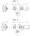
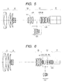
- Figs. 1 to 6 show the cross-sectional configurations of lenses, of zoom lenses according to the first embodiment of the present invention, which are located at the wide-angle end and infinity focus position in the first to sixth numerical embodiments.
- a first unit (front element) I has a positive refractive power
- a variator II serves as the second unit having a negative refractive power and capable of moving in the optical axis direction in magnification changing operation.
- the second unit II is monotonously moved to the image side on the optical axis to change the magnification from the wide-angle end to the telephoto end.
- magnification changing operation the second unit II is moved within a range including an imaging magnification of 1 ⁇ (-1 ⁇ ) (i.e. equal magnification).
- a compensator III serves as the third unit which can move in the optical axis direction to correct an image plane fluctuation accompanying magnification changing operation.
- a stop SP is used for light amount adjustment.
- a fourth unit IV having a positive refractive power is used for imaging.
- a glass block G is a color separation prism, optical filter, or the like.
- a wobbling unit wo can be slightly amplitude-driven in the optical axis direction to detect the best imaging position.
- a lens unit L4b is placed immediately before the wobbling unit in the fourth unit.
- An extender (magnification changing optical unit) EX for increasing or decreasing the overall focal length of the zoom lens system can be inserted/removed (or mounted/dismounted) in/from the space in the fourth unit.
- the configuration of a lens unit located closer to the image side than the stop SP is properly set such that a change in imaging magnification accompanying wobbling of the wobbling unit wo is reduced regardless of whether the extender EX is inserted/removed.
- the wobbling unit wo needs to be amplitude-driven at high speed in the optical axis direction. It is therefore preferable that the wobbling unit wo have a proper backfocus sensitivity degree and be light in weight.
- a zoom lens for a TV set needs to have a long backfocus and a small F-number, and hence requires many lenses constituting each unit.
- each lens has a large effective diameter, and an extender, macro photographing mechanism, flange-back adjustment mechanism, and the like must be arranged in the relay unit, resulting in a low degree of freedom in placing the wobbling unit.
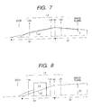
- Figs. 7 and 8 schematically show lens units behind the stop SP.
- Fig. 7 shows a state where the extender EX is not inserted.
- Fig. 8 shows a state where the extender EX is inserted. Referring to Fig. 8, the magnification of the extender EX is set to 2 ⁇ , and an image is enlarged by 2 ⁇ on an image plane.
- parameters that change upon insertion/removal of the extender EX and have great influences on the image height change ratio ⁇ y/fw are the incident angle ⁇ 1 of a principal ray on the wobbling unit wo and (S1 - E1).
- the allowable value of the wobbling amount ⁇ x will be described. It is said that the resolution of the visual sense of a person having 20/20 vision is about one minute. If, for example, the person watches a 30-inch TV screen (having a screen size of about 50 cm in the horizontal direction) at a distance of 2.5 m, the viewing angle in the horizontal direction becomes about 680 minutes. A resolution of one minute therefore corresponds to 0.15% of the screen.
- the depth of focus increases as compared with that at full aperture.
- a larger wobbling amount is required to detect the best focus position, and hence the image height change ratio increases.
- an image height change ratio is allowed at most 0.15% at F/5.6.
- An allowable value at full aperture (F/1.752) becomes about 0.06% which is about 1/3 the image height change ratio at F/5.6.
- the upper limit of conditional expression (1) is determined such that the image height change ratio at full aperture (F/1.752) falls within an image height change ratio of 0.06% (0.15% at F/5.6), and falls within the allowable range even if the image height change ratio changes upon insertion of the extender EX.
- ⁇ x ⁇ sk (1- ⁇ 2 1 ) ⁇ 2 2
- ⁇ 1 is a lateral magnification of the wobbling unit
- ⁇ 2 is a lateral magnification of an optical system placed at the image side with respect to the wobbling unit.
- the wobbling lens unit is disposed closer to the image side than the magnification changing optical unit capable of being inserted and removed, so that the wobbling amount ⁇ x has a relation proportional to the F-number since both ⁇ 1 and ⁇ 2 are constant before/after insertion of the magnification changing optical system.
- the F-number in practical use at the time of insertion of the 2x extender falls within a narrow range of about F/4 to F/5.6 because the F-number at the full aperture end increases. For this reason, if a maximum of 0.15% of the value at F/5.6 is allowed at the time of insertion of the extender, the allowable amount at full aperture (F/4) becomes about 0.1%. That is, an allowable amount as large as double the value before the insertion of the extender can be allowed.
- the allowable upper limit value of an image height change ratio indicated by conditional expressions (1) and (2) is the value set when the wobbling unit is amplitude-driven in the optical axis direction such that the amplitude halfwidth of a change in backfocus becomes 1/2 the depth of focus.
- this value changes depending on the manner of determining a wobbling amount with respect to the depth of focus (e.g., setting the amplitude halfwidth to 1/3 the depth of focus or to be equal to it), an assumed screen size, and the like.
- conditional expression (1) With approach to the lower limit value of conditional expression (1), a change in imaging magnification while the extender is not inserted is reduced, and an ideal condition is obtained.
- This condition is not necessarily a desired condition for an optical system in/from which the extender is inserted/removed.
- the refractive power ⁇ 4b of the lens unit L4b located immediately before the wobbling unit wo in the fourth unit IV preferably satisfies -0.001 ⁇ ⁇ 4b/Im ⁇ 0.0015 where Im is the image size of the image pickup element.
- the incident angle of a principal ray on the wobbling unit wo greatly changes from ⁇ 1 to ⁇ 2 or from ⁇ 2 to ⁇ 1, and a change in imaging magnification becomes large under one of the conditions.
- ⁇ x 2 F ⁇ x 1 where ⁇ x 1 is an amplitude halfwidth of the wobbling unit before insertion of the magnification changing optical system, ⁇ x 2 is an amplitude halfwidth of the wobbling unit after insertion of the magnification changing optical system, and F is a rate of change of F-number due to insertion/removal of the magnification changing optical system.
- X (1/ R ) H 2 1+ 1-( H / R ) 2 + BH 4 + CH 6 + DH 8 + EH 10
- the extender EX is preferably placed in a substantially afocal parallel light beam.
- a wide gap is required to satisfy the extender magnification requirement and optical performance requirement.
- three lenses of which form two units in the fourth unit and are located closest to the image side, are used as wobbling unit lenses.
- a reduction in the weight of the wobbling unit wo is achieved.
- a change in imaging magnification is small regardless of the presence/absence of the extender EX.
- Table 12 shows the numerical values of conditional expressions and imaging magnification change ratios in the respective numerical embodiments.
- Each imaging magnification change ratio is the value obtained when wobbling is performed upon setting the amplitude halfwidth to 1/2 the depth of focus at the full aperture end.
- the permissible circle of confusion of a 2/3-inch CCD image size: ⁇ 11 mm which is the mainstream in TV cameras is set to about 0.021 mm, the depth of focus at F/2 becomes about 0.04 mm.
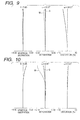
- Figs. 9 and 10 are aberration diagrams at the wide-angle end and telephoto end without insertion of the extender in the first numerical embodiment.
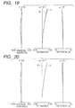
- Fig. 19 is an aberration diagram at the wide-angle end with insertion of the extender.
- the second lens located closer to the image side than the insertion gap of the extender EX is used as a wobbling unit lens.
- the lens unit L4c constituted by six lenses which form four units in the fourth unit and are located closer to the image side than the wobbling unit wo are constituted by two lens units L4c1 and L4c2.
- the use of the lens unit L4c2 allows macro photographing for proximity photographing and flange-back adjustment for adjusting the dimensional error between the reference surface of a lens (flange surface) and an image plane in a lens-interchangeable camera, independently of the main focusing lens.
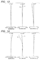
- Figs. 11 and 12 are aberration diagrams at the wide-angle end and telephoto end without insertion of the extender in the numerical embodiment 1.
- Fig. 20 is an aberration diagram at the wide-angle end with insertion of the extender.
- the extender can be inserted in the space with d24 to d26 by retracting (ejecting) part (L4b) of the fourth unit from the optical axis at the time of insertion of the extender EX.
- retracting part of the fourth unit By retracting part of the fourth unit, a reduction in the space for insertion/removal of the extender can be attained. This makes it possible to achieve a reduction in the size of the lens system and suppress a deterioration in optical performance at the time of insertion of the extender by effectively using the wide space.
- an appropriate imaging magnification change ratio can be kept by properly setting the refractive power of the lens unit L4b.
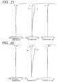
- Fig. 21 is an aberration diagram at the wide-angle end at the time of insertion of the extender in the numerical embodiment 3.
- the second lens located closer to the image side than the insertion gap for the extender EX is used as a wobbling unit lens.
- the lens unit L4b located closer to the object side than the wobbling unit wo has a negative refractive power.
- ⁇ 4b is brought closer to the lower limit, a change in imaging magnification (conditional expression (2)) accompanying insertion of the extender EX takes a large value.
- Figs. 13 and 14 are aberration diagrams at the wide-angle end and telephoto end without insertion of the extender in the numerical embodiment 4.
- Fig. 22 is an aberration diagram at the wide-angle end with insertion of the extender.
- the wobbling unit wo has a negative refractive power.
- ⁇ 4b is brought closer to the upper limit, a change in imaging magnification (conditional expression (2)) accompanying insertion/removal of the extender takes a large value.
- the unit L4c is integrally moved to allow macro photographing and flange-back adjustment.
- Figs. 15 and 16 are aberration diagrams at the wide-angle end and telephoto end without insertion of the extender in the numerical embodiment 5.
- Fig. 23 is an aberration diagram at the wide-angle end with insertion of the extender.
- an optical system is placed in the space in the fourth unit, in/from which the extender EX is inserted/removed, instead of setting a large space as an air gap at the time of 1x, and the optical system at the time of 1x is retracted (ejected) from the optical axis upon insertion of the extender.
- the lens units located closer to the object side than the extender EX are fixed regardless of insertion/removal of the extender EX.
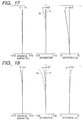
- Figs. 17 and 18 are aberration diagrams at the wide-angle end and telephoto end without insertion of the extender in the numerical embodiment 6.
- Fig. 24 is an aberration diagram at the wide-angle end with insertion the extender.
- a zoom lens suitable for a TV camera, video camera, or the like which has a large aperture of an F-number of about 1.8 to 2 and a high magnification ratio of 10 ⁇ or more, exhibits a small change in imaging magnification accompanying wobbling regardless of insertion/removal of an optical system such as the extender EX in the relay unit, and has excellent optical performance throughout the entire magnification change range.
- a photographing system (TV camera system) using one of the zoom lenses in the numerical embodiments 1 to 6 as a photographing optical system will be described next with reference to Fig. 25.
- this photographing system includes a photographing system body 106 including lenses, a photographing optical system 101 formed by one of the zoom lenses in the numerical embodiments 1 to 6, a glass block 102 corresponding to a filter or color separation prism, an image pickup element 103 such as a CCD for receiving an object image formed by the photographing optical system 101, and CPUs 104 and 105 for controlling the photographing system and lenses.
- a photographing system By using one of the zoom lenses in the numerical embodiments 1 to 6 for a photographing system such as a TV camera, a photographing system can be realized, in which a change in imaging magnification upon slight amplitude driving of a wobbling unit wo in the optical axis direction for autofocus operation is small regardless of whether an extender EX is inserted/removed, i.e., poor screen display can be prevented.
- the present invention is not limited to the zoom lenses shown in Figs. 1 to 6.
- a lens unit other than the lens units shown in Figs. 1 to 6 may be added to the zoom lens.
- the lens unit may be constituted by I, II, III, IV, and V units.
- the same reference numerals as in Fig. 26 denote the same parts in Fig. 25.
- a change in imaging magnification caused when the wobbling unit is slightly amplitude-driven in the optical axis direction can be suppressed small regardless of the insertion/removal of the magnification changing optical unit.
- conditional expression (1) if conditional expression (1) is satisfied, a change in imaging magnification accompanying wobbling without insertion of the magnification changing optical unit can be sufficiently suppressed small.
- conditional expression (2) If conditional expression (2) is satisfied, a change in imaging magnification accompanying wobbling with insertion of the magnification changing optical unit can be sufficiently suppressed small.
- conditional expression (3) If conditional expression (3) is satisfied, a change in incident angle on the wobbling unit upon insertion/removal of the magnification changing optical unit can be made small. This makes it possible to reduce a change in imaging magnification more reliably.
- this system is designed to retract part of the fourth unit from the optical axis by inserting the magnification changing optical unit, a large space for the insertion of the magnification changing optical unit can be ensured while a reduction in the overall size of the zoom lens is attained. This makes it possible to suppress a deterioration in optical performance at the time of insertion of the magnification changing optical unit.
Landscapes
- Physics & Mathematics (AREA)
- General Physics & Mathematics (AREA)
- Optics & Photonics (AREA)
- Lenses (AREA)
- Structure And Mechanism Of Cameras (AREA)
- Lens Barrels (AREA)
Abstract
Description
- The present invention relates to a zoom lens suitable for a TV camera, video camera, and the like.
- As an autofocus (AF) system in a video camera or the like, a system called "hill-climbing AF" which obtains the distance to a principal object and drives a focus unit to an appropriate position is widely used.
- In this system, the direction of the best imaging position is detected from a change in a video signal by using some of the lens units of an image pickup system for imaging, and the extension direction of a focusing lens is calculated. A merit of this system is that no optical system need be newly used for distance measurement.
- In addition, in this system, in order to check whether the best imaging position is located before or after the image pickup surface (CCD surface or film surface), a partial optical system of the image pickup system is slightly amplitude-driven (to be referred to as wobbled hereinafter) in the optical axis direction. A focus unit is driven to set the best focus on the image pickup surface on the basis of the detected signal.
- At this time, since part of the optical system is wobbled, the imaging magnification greatly changes to result in poor screen display unless lens units and the like are properly arranged.
- As a method of reducing a change in imaging magnification, the method disclosed in Japanese Patent No. 2744336 is available. This method is associated with a rear focus zoom lens which has the first unit having a positive refractive power, the second unit having a negative refractive power for magnification changing operation, the third unit having a positive refractive power, and the fourth unit having a positive refractive power and serving to correct an image plane fluctuation with a change in magnification, and is designed to perform focusing by using the fourth unit.
- A change in imaging magnification accompanying wobbling can be expressed by a paraxial trace. Several conditions for suppressing a change in imaging magnification accompanying wobbling small are described in USP 5,138,492.
- These conditions are, however, insufficient to be applied to an image pickup system which has a wobbling lens unit placed in a relay lens unit located closer to the image side than the stop and allows insertion/removal of an extender for shifting the focal length to the telephoto side.
- More specifically, the conditions described in the above reference are effective for a method of reducing a change in imaging magnification in a state where an optical arrangement behind the stop is fixed, but are not sufficient to be applied to a case wherein the arrangement of an optical system is changed upon insertion/removal of an extender or the like and the incident angle of an off-axis principal ray on a wobbling lens unit, in particular, changes.
- It is an object of the present invention to provide a 4-unit zoom lens which exhibits a small change in imaging magnification accompanying wobbling even with insertion of an optical system such as an extender in the fourth unit serving as a relay lens unit and also exhibits excellent optical performance throughout the entire magnification change range.
- In order to achieve the above object, according to the present invention, in a zoom lens in/from which a magnification changing optical unit for changing an overall focal length of the zoom lens can be inserted/removed, a wobbling unit which can be slightly amplitude-driven in an optical axis direction to detect a best imaging position is placed closer to an image side than an insertion position of the magnification changing optical unit.
- With this arrangement, a change in imaging magnification caused when the wobbling unit is slightly driven in the optical axis direction can be reduced regardless of insertion/removal of the magnification changing optical unit.
- The zoom lens sequentially includes, from an object side, a first unit which is fixed in magnification changing operation and has a positive refractive power, a second unit which moves in the optical axis direction in magnification changing operation and has a negative refractive power, a third unit for correcting an image plane fluctuation accompanying magnification changing operation, and a fourth unit having a positive refractive power for imaging, and a magnification changing optical unit which changes the overall focal length of the zoom lens can be inserted/removed in/from the fourth unit. In this zoom lens, a wobbling unit which can be slightly amplitude-driven in the optical axis direction to detect a best imaging position is placed closer to the image side than the insertion position of the magnification changing optical unit, and a stop for adjustment of light amount is preferably disposed at the object side with respect to the fourth unit.
- More specifically, for example, when the wobbling unit is placed in the fourth unit and amplitude-driven to make an amplitude halfwidth of a backfocus change amount become 1/2 a depth of focus,
- With this arrangement, a change in imaging magnification accompanying wobbling without insertion of the magnification changing optical unit can be suppressed sufficiently small.
- In addition, when the wobbling unit is placed in the fourth unit amplitude-driven to make an amplitude halfwidth of a backfocus change amount become 1/2 a depth of focus,
- In addition, in the fourth unit,
- With this arrangement, a change in incident angle on the wobbling unit upon insertion/removal of the magnification changing optical unit can be made small. This makes it possible to reduce a change in imaging magnification more reliably.
- Further, the amplitude halfwidth of the wobbling unit before/after insertion of the magnification changing optical system is preferably so set as to satisfy the following condition (4).
- Note that a reduction in the size and weight of the wobbling unit to be slightly amplitude-driven may be attained by placing the wobbling unit closest to the image side in the fourth unit.
- If this system is designed to retract part of the fourth unit from the optical axis by inserting the magnification changing optical unit, a large space for the insertion of the magnification changing optical unit can be ensured while a reduction in the overall size of the zoom lens is attained. This makes it possible to suppress a deterioration in optical performance at the time of insertion of the magnification changing optical unit.
-
- Fig. 1 is a sectional view of a zoom lens according to the first embodiment of the present invention at the wide-angle end in the first numerical embodiment;
- Fig. 2 is a sectional view of a zoom lens according to the first embodiment of the present invention at the wide-angle end in the second numerical embodiment;
- Fig. 3 is a sectional view of a zoom lens according to the first embodiment of the present invention at the wide-angle end in the third numerical embodiment;
- Fig. 4 is a sectional view of a zoom lens according to the first embodiment of the present invention at the wide-angle end in the fourth numerical embodiment;
- Fig. 5 is a sectional view of a zoom lens according to the first embodiment of the present invention at the wide-angle end in the fifth numerical embodiment;
- Fig. 6 is a sectional view of a zoom lens according to the first embodiment of the present invention at the wide-angle end in the sixth numerical embodiment;
- Fig. 7 is a schematic view showing an optical configuration after the stop of the zoom lens according to the first embodiment (without insertion of an extender);
- Fig. 8 is a schematic view showing an optical configuration after the stop of the zoom lens according to the first embodiment (with insertion of the extender);
- Fig. 9 is an aberration diagram at the wide-angle end in the first numerical embodiment;
- Fig. 10 is an aberration diagram at the telephoto end in the first numerical embodiment;
- Fig. 11 is an aberration diagram at the wide-angle end in the second numerical embodiment;
- Fig. 12 is an aberration diagram at the telephoto end in the second numerical embodiment;
- Fig. 13 is an aberration diagram at the wide-angle end in the fourth numerical embodiment;
- Fig. 14 is an aberration diagram at the telephoto end in the fourth numerical embodiment;
- Fig. 15 is an aberration diagram at the wide-angle end in the fifth numerical embodiment;
- Fig. 16 is an aberration diagram at the telephoto end in the fifth numerical embodiment;
- Fig. 17 is an aberration diagram at the wide-angle end in the sixth numerical embodiment;
- Fig. 18 is an aberration diagram at the telephoto end in the sixth numerical embodiment;
- Fig. 19 is an aberration diagram at the wide-angle end in the first numerical embodiment at the time of insertion of the extender;
- Fig. 20 is an aberration diagram at the wide-angle end in the second numerical embodiment at the time of insertion of the extender;
- Fig. 21 is an aberration diagram at the wide-angle end in the third numerical embodiment at the time of insertion of the extender;
- Fig. 22 is an aberration diagram at the wide-angle end in the fourth numerical embodiment at the time of insertion of the extender;
- Fig. 23 is an aberration diagram at the wide-angle end in the fifth numerical embodiment at the time of insertion of the extender;
- Fig. 24 is an aberration diagram at the wide-angle end in the sixth numerical embodiment at the time of insertion of the extender;
- Fig. 25 is a view showing the arrangement of a photographing system using the zoom lens according to the first embodiment as a photographing optical system; and
- Fig. 26 is view showing a photographing system according to another embodiment of the present invention.
-
- Figs. 1 to 6 show the cross-sectional configurations of lenses, of zoom lenses according to the first embodiment of the present invention, which are located at the wide-angle end and infinity focus position in the first to sixth numerical embodiments.
- Referring to Figs. 1 to 6, a first unit (front element) I has a positive refractive power, and a variator II serves as the second unit having a negative refractive power and capable of moving in the optical axis direction in magnification changing operation. The second unit II is monotonously moved to the image side on the optical axis to change the magnification from the wide-angle end to the telephoto end. In magnification changing operation, the second unit II is moved within a range including an imaging magnification of 1× (-1×) (i.e. equal magnification).
- A compensator III serves as the third unit which can move in the optical axis direction to correct an image plane fluctuation accompanying magnification changing operation.
- A stop SP is used for light amount adjustment. A fourth unit IV having a positive refractive power is used for imaging.
- A glass block G is a color separation prism, optical filter, or the like. A wobbling unit wo can be slightly amplitude-driven in the optical axis direction to detect the best imaging position. A lens unit L4b is placed immediately before the wobbling unit in the fourth unit.
- An extender (magnification changing optical unit) EX for increasing or decreasing the overall focal length of the zoom lens system can be inserted/removed (or mounted/dismounted) in/from the space in the fourth unit.
- In this embodiment, the configuration of a lens unit (to be referred to as a relay unit hereinafter) located closer to the image side than the stop SP is properly set such that a change in imaging magnification accompanying wobbling of the wobbling unit wo is reduced regardless of whether the extender EX is inserted/removed.
- The wobbling unit wo needs to be amplitude-driven at high speed in the optical axis direction. It is therefore preferable that the wobbling unit wo have a proper backfocus sensitivity degree and be light in weight. A zoom lens for a TV set needs to have a long backfocus and a small F-number, and hence requires many lenses constituting each unit. In addition, each lens has a large effective diameter, and an extender, macro photographing mechanism, flange-back adjustment mechanism, and the like must be arranged in the relay unit, resulting in a low degree of freedom in placing the wobbling unit.
- Figs. 7 and 8 schematically show lens units behind the stop SP. Fig. 7 shows a state where the extender EX is not inserted. Fig. 8 shows a state where the extender EX is inserted. Referring to Fig. 8, the magnification of the extender EX is set to 2×, and an image is enlarged by 2× on an image plane.
- Referring to Fig. 7, an image height change ratio can be expressed as follows. Letting α1 be the incident angle of sub-principal ray on the wobbling unit wo, wo be the power of the wobbling unit wo, S1 be the distance between the wobbling unit wo and an image plane, 4c be the power of lens unit L4c located closer to the image side than the wobbling unit wo, Δx be the wobbling amount, (S1 - E1) be the difference between the distance to a virtual image of the stop SP viewed from the wobbling unit wo and the distance to a virtual image of the image plane viewed from the wobbling unit wo, and Δy be the image height change amount at the time of wobbling, an image height change ratio Δy/fw (where fw is the focal length of the overall system at the wide-angle end) can be expressed by
- The wobbling amount Δx is a sufficiently small value relative to (S1 - E1), and hence can be expressed by
- In the configuration of the zoom lens according to this embodiment, parameters that change upon insertion/removal of the extender EX and have great influences on the image height change ratio Δy/fw are the incident angle α1 of a principal ray on the wobbling unit wo and (S1 - E1).
- The allowable value of the wobbling amount Δx will be described. It is said that the resolution of the visual sense of a person having 20/20 vision is about one minute. If, for example, the person watches a 30-inch TV screen (having a screen size of about 50 cm in the horizontal direction) at a distance of 2.5 m, the viewing angle in the horizontal direction becomes about 680 minutes. A resolution of one minute therefore corresponds to 0.15% of the screen.
- If the lens is stopped down, the depth of focus increases as compared with that at full aperture. In addition, a larger wobbling amount is required to detect the best focus position, and hence the image height change ratio increases.
- In consideration of the fact that the highest frequency in use of an F-number range is about full aperture: F/5.6, an image height change ratio is allowed at most 0.15% at F/5.6. An allowable value at full aperture (F/1.752) becomes about 0.06% which is about 1/3 the image height change ratio at F/5.6. The upper limit of conditional expression (1) is determined such that the image height change ratio at full aperture (F/1.752) falls within an image height change ratio of 0.06% (0.15% at F/5.6), and falls within the allowable range even if the image height change ratio changes upon insertion of the extender EX.
- The relationship between the wobbling amount Δx and the change amount in backfocus Δsk is expressed by
- In the present invention, the wobbling lens unit is disposed closer to the image side than the magnification changing optical unit capable of being inserted and removed, so that the wobbling amount Δx has a relation proportional to the F-number since both β1 and β2 are constant before/after insertion of the magnification changing optical system.
- Considering the wobbling amount after insertion of a 2× extender, since the F-number becomes doubled, the depth of focus also becomes doubled. The amplitude driving amount of the wobbling unit must also be doubled.
- The F-number in practical use at the time of insertion of the 2x extender falls within a narrow range of about F/4 to F/5.6 because the F-number at the full aperture end increases. For this reason, if a maximum of 0.15% of the value at F/5.6 is allowed at the time of insertion of the extender, the allowable amount at full aperture (F/4) becomes about 0.1%. That is, an allowable amount as large as double the value before the insertion of the extender can be allowed.
- The allowable upper limit value of an image height change ratio indicated by conditional expressions (1) and (2) is the value set when the wobbling unit is amplitude-driven in the optical axis direction such that the amplitude halfwidth of a change in backfocus becomes 1/2 the depth of focus. In practice, this value changes depending on the manner of determining a wobbling amount with respect to the depth of focus (e.g., setting the amplitude halfwidth to 1/3 the depth of focus or to be equal to it), an assumed screen size, and the like.
- Considering a system frequency using F-numbers equal to or larger than F/5.6 or setting of smaller full aperture F-numbers, a system is required in which the image height change ratio at full aperture is further suppressed and a change before/after insertion of an extender is smaller.
- Consider only a state where no extender is inserted. In this case, to reduce a change in imaging magnification accompanying wobbling, the incident angle α1 of a sub-principal ray on the wobbling unit and the difference (S1 - E1) between the distance E1 to the stop viewed from the wobbling unit and the distance S1 to the image plane viewed from the wobbling unit must be reduced.
- When the extender EX in the state shown in Fig. 7 is inserted (Fig. 8), the incident angle of sub-principal ray on the wobbling unit wo changes to α2, and a distance E2 to the stop SP viewed from the wobbling unit wo changes. However, a distance S2 to the image plane viewed from the wobbling unit wo is almost constant (S2 ≃ S1) regardless of insertion/removal of the extender, and hence a change in imaging magnification at the time of insertion of the extender remains.
- In order to reduce a change in imaging magnification accompanying wobbling in a state where the extender is not inserted, the following condition must be satisfied:
- With approach to the lower limit value of conditional expression (1), a change in imaging magnification while the extender is not inserted is reduced, and an ideal condition is obtained.
- While the extender is inserted, it is difficult to cancel out the distance E2 with respect to the distance S2 in Fig. 8, and a change in imaging magnification remains. This condition is not necessarily a desired condition for an optical system in/from which the extender is inserted/removed.
- If the upper limit value is exceeded, a change in imaging magnification without insertion of the extender is large. It indicates that this condition is not suitable for wobbling.
- Therefore, while the extender is inserted, the following is preferably satisfied:
- If the upper limit value of this conditional expression (2) is exceeded, it indicates that a change in imaging magnification at the time of insertion/removal of the extender is large.
- In addition, the refractive power 4b of the lens unit L4b located immediately before the wobbling unit wo in the fourth unit IV preferably satisfies
- If the positive or negative refractive power of the lens unit L4b is increased beyond the range of conditional expression (3), the incident angle of a principal ray on the wobbling unit wo greatly changes from α1 to α2 or from α2 to α1, and a change in imaging magnification becomes large under one of the conditions.
- It is preferable to set the amplitude amount of the wobbling unit to the following condition (4) before/after insertion of the magnification changing optical system.
- The numerical embodiments of this embodiment will be described below. In the numerical embodiments 5 to 6, let ri be the radius of curvature of the ith lens from the object side, di be the thickness or air gap of the ith optical member from the object side, and ni and γi ("vi" in the tables) be the refractive index and Abbe number, respectively, of the glass of the ith lens from the object side with respect to a d line.
- Letting the X-axis be the optical axis direction, the H-axis be a direction perpendicular to the optical axis, a traveling direction of light be positive, R be the paraxial radius of curvature, and B, C, D, and E be aspherical coefficients, an aspherical shape is expressed by
-
Numerical Embodiment 1 f =9.50∼185.25 Fno:1.85∼2.85 2ω:60.1° ∼3.4° r 1= 600.261 d 1= 2.20 n 1=1.76168 ν 1- 27.5 r 2= 81.461 d 2= 11.42 n 2=1.49845 ν 2= 81.6 r 3= -290.956 d 3= 7.63 r 4= 86.701 d 4= 7.86 n 3=1.62287 ν 3= 60.3 r 5=3044.710 d 5= 0.15 r 6= 66.016 d 6= 6.01 n 4=1.73234 ν 4= 54.7 r 7= 145.708 d 7=Variable r 8= 111.445 d 8= 0.80 n 5=1.88814 ν 5= 40.8 r 9= 16.812 d 9= 4.65 r10= -47.842 d10= 0.70 n 6=1.82017 ν 6= 46.6 r11= 33.779 d11= 2.24 r12= 28.944 d12= 5.20 n 7=1.81264 ν 7= 25.4 r13= -29.192 d13= 0.54 r14= -24.664 d14= 0.70 n 8=1.79196 ν 8= 47.4 r15= 132.572 d15=Variable r16= -28.806 d16= 0.75 n 9=1.74679 ν 9= 49.3 r17= 37.218 d17= 3.81 n10=1.85501 ν10= 23.9 r18= 449.023 d18=Variable r19= ∞(stop) d19= 1.80 r20= -231.233 d20= 3.33 n11=1.67340 ν11= 47.2 r21= -49.133 d21= 0.20 r22= -170.365 d22= 4.05 n12=1.51976 ν12= 52.4 r23= -38.625 d23= 0.20 r24= 36.315 d24= 10.16 n13=1.48915 ν13= 70.2 r25= -35.564 d25= 1.66 n14=1.83932 ν14= 37.2 r26= 0.000 d26= 36.00 r27= 97.385 d27= 6.36 n15=1.50349 ν15= 56.4 r28= -44.438 d28= 0.20 r29= -535.654 d29= 1.40 n16=1.83932 ν16= 37.2 r30= 21.016 d30= 7.22 n17=1.50349 ν17= 56.4 r31= -424.093 d31= 1.50 r32= 38.505 d32= 8.29 n18=1.62033 ν18= 58.9 r33= -27.482 d33= 1.40 n19=1.77621 ν19= 49.6 r34= 91.360 d34= 0.30 r35= 38.429 d35= 6.84 n20=1.53430 ν20= 48.8 r36= -52.407 d36= 5.00 r37= ∞ d37= 30.00 n21=1.60718 ν21= 38.0 r38= ∞ d38= 16.20 n22=1.51825 ν22= 64.2 r39= ∞ Extender Portion d26= 1.60 r27= 64.675 d27= 6.74 n15=1.49845 ν15= 81.5 r28= -54.795 d28= 0.20 r29= 25.068 d29= 6.49 n16=1.49845 ν16= 81.5 r30= -128.700 d30= 0.80 n17=1.85501 ν17= 23.9 r31= 56.237 d31= 11.25 r32= -106.936 d32= 0.90 n18=1.64254 ν18= 60.1 r33= 10.653 d33= 2.65 n19=1.85501 ν19= 23.9 r34= 14.647 d34= 5.37 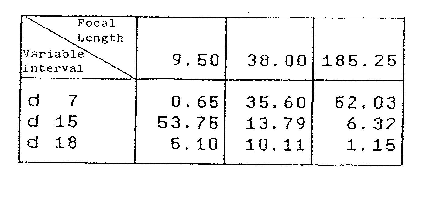
- In the numerical embodiment 1 shown in Fig. 1, to reduce variations in optical performance upon insertion of the extender EX, the extender EX is preferably placed in a substantially afocal parallel light beam. In addition, a wide gap is required to satisfy the extender magnification requirement and optical performance requirement.
- As a wobbling unit which satisfies conditional expression (1), has a proper backfocus sensitivity degree accompanying slight amplitude driving of the wobbling unit wo, and exhibits a small change in imaging magnification, all or some of lens units located closer to the image side than the extender EX are preferably used.
- In the numerical embodiment 1, three lenses of which form two units in the fourth unit and are located closest to the image side, are used as wobbling unit lenses. By making some lenses of the fourth unit movable, a reduction in the weight of the wobbling unit wo is achieved. In addition, by setting the refractive power of the lens unit L4b located immediately before the wobbling unit within the range of conditional expression (3), a change in imaging magnification is small regardless of the presence/absence of the extender EX.
- In the numerical embodiment 1, the extender EX can be inserted/removed in/from a space with gap d26 = 36 mm.
- Table 12 shows the numerical values of conditional expressions and imaging magnification change ratios in the respective numerical embodiments. Each imaging magnification change ratio is the value obtained when wobbling is performed upon setting the amplitude halfwidth to 1/2 the depth of focus at the full aperture end.
- If, for example, the permissible circle of confusion of a 2/3-inch CCD (image size: 11 mm) which is the mainstream in TV cameras is set to about 0.021 mm, the depth of focus at F/2 becomes about 0.04 mm.
- Figs. 9 and 10 are aberration diagrams at the wide-angle end and telephoto end without insertion of the extender in the first numerical embodiment. Fig. 19 is an aberration diagram at the wide-angle end with insertion of the extender.
-
Numerical Embodiment 2 f =9.50∼185.25 Fno:2.0∼2.85 2ω:60.1° ∼3.4° r 1= 622.723 d 1= 2.20 n 1=1.76168 ν 1= 27.5 r 2= 77.855 d 2= 12.34 n 2=1.48915 ν 2= 70.2 r 3= -323.998 d 3= 7.78 r 4= 86.923 d 4= 8.56 n 3=1.62032 ν 3= 63.4 r 5= -1529.464 d 5= 0.15 r 6= 64.688 d 6= 6.06 n 4=1.73234 ν 4= 54.7 r 7= 134.784 d 7=Variable r 8= 111.445 d 8= 0.80 n 5=1.88814 ν 5= 40.8 r 9= 16.812 d 9= 4.65 r10= -47.842 d10= 0.70 n 6=1.82017 ν 6= 46.6 r11= 33.779 d11= 2.24 r12= 28.944 d12= 5.20 n 7=1.81264 ν 7= 25.4 r13= -29.192 d13= 0.54 r14= -24.664 d14= 0.70 n 8=1.79196 ν 8= 47.4 r15= 132.572 d15=Variable r16= -28.806 d16= 0.75 n 9=1.74679 ν 9= 49.3 r17= 37.218 d17= 3.81 n10=1.85501 ν10= 23.9 r18= 449.023 d18=Variable r19= ∞ (Stop) d19 = 1.40 r20= -1109.872 d20= 4.46 n11=1.67340 ν11= 47.2 r21= -30.372 d21= 0.20 r22= 104.731 d22= 6.31 n12=1.48915 ν12= 70.2 r23= -26.574 d23= 1.20 n13=1.83932 ν13= 37.2 r24= -74.569 d24= 30.00 r25= 170.165 d25= 3.69 n14=1.48915 ν14= 70.2 r26= -86.018 d26= 2.50 r27= 46.559 d27= 4.04 n15=1.69979 ν15= 55.5 r28= 178.870 d28= 6.00 r29= -66.299 d29= 1.20 n16=1.08815 ν16= 40.8 r30= 151.817 d30= 7.03 n17=1.48915 ν17= 70.2 r31= -37.731 d31= 0.15 r32= 74.679 d32= 1.20 n18=1.80642 ν18= 35.0 r33= 28.773 d33= 4.28 r34= 78.908 d34= 8.64 n19=1.52033 ν19= 58.9 r35= -20.059 d35= 1.20 n20=1.88815 ν20= 40.8 r36= -66.519 d36= 4.03 r37= 1248.781 d37= 4.71 n21=1,66152 ν21= 50.9 r38= -35.175 d38= 4.00 r39= ∞ d39= 30.00 n22=1.60718 ν22= 38.0 r40= ∞ d40= 16.20 n23=1.51825 ν23= 64.2 r41= ∞ Extender Portion d24= 1.60 r25= -377.563 d25= 2.81 n14=1.52033 ν14= 58.9 r26= -49.635 d26= 0.20 r27= 19.162 d27= 5.72 n15=1.51976 ν15= 52.4 r28= 96.555 d28= 0.20 r29= 15.020 d29= 5.62 n16=1.51825 ν16= 64.1 r30= 137.066 d30= 0.80 n17=1.85501 ν17= 23.9 r31= 10.484 d31= 6.63 r32= -49.330 d32= 0.90 n18=1.64254 ν18= 60.1 r33= 11.941 d33= 2.99 n19=1.85501 ν19= 23.9 r34= 30.819 d34= 2.67 
- In the numerical embodiment 2 shown in Fig. 2, the second lens located closer to the image side than the insertion gap of the extender EX is used as a wobbling unit lens. The extender EX can be inserted/removed in/from a space with d24 = 30 mm.
- Since the positive refractive power 4b of the lens unit L4b located immediately before the wobbling unit wo is brought near to the upper limit in the numerical embodiment 1, a change (conditional expression (2)) in imaging magnification upon insertion/removal of the extender takes a large value.
- The lens unit L4c constituted by six lenses which form four units in the fourth unit and are located closer to the image side than the wobbling unit wo are constituted by two lens units L4c1 and L4c2. In addition, the use of the lens unit L4c2 allows macro photographing for proximity photographing and flange-back adjustment for adjusting the dimensional error between the reference surface of a lens (flange surface) and an image plane in a lens-interchangeable camera, independently of the main focusing lens.
- Figs. 11 and 12 are aberration diagrams at the wide-angle end and telephoto end without insertion of the extender in the numerical embodiment 1. Fig. 20 is an aberration diagram at the wide-angle end with insertion of the extender.
-
Numerical Embodiment 3 Extender Portion d24= 1.60 r25= 722.998 d25= 3.37 n14=1.52033 ν14= 58.9 r26= -69.098 d26= 0.20 r27= 21.904 d27= 5.85 n15=1.51976 ν15= 52.4 r28= 156.887 d28= 0.20 r29= 17.349 d29= 5.19 n16=1.51825 ν16= 64.1 r30= 117.012 d30= 0.80 n17=1.85501 ν17= 23.9 r31= 12.697 d31= 8.57 r32= 378.277 d32= 0.90 n18=1.64254 ν18= 60.1 r33= 12.453 d33=3.62 n19=1.85501 ν19= 23.9 r34= 25.927 d34= 6.00 - In contrast to the lens system in the numerical embodiment 2, in the numerical embodiment 3 shown in Fig. 3, the extender can be inserted in the space with d24 to d26 by retracting (ejecting) part (L4b) of the fourth unit from the optical axis at the time of insertion of the extender EX. By retracting part of the fourth unit, a reduction in the space for insertion/removal of the extender can be attained. This makes it possible to achieve a reduction in the size of the lens system and suppress a deterioration in optical performance at the time of insertion of the extender by effectively using the wide space.
- Even in a case where part of the fourth unit is retracted at the time of insertion of the extender, an appropriate imaging magnification change ratio can be kept by properly setting the refractive power of the lens unit L4b.
- Fig. 21 is an aberration diagram at the wide-angle end at the time of insertion of the extender in the numerical embodiment 3.
-
Numerical Embodiment 4 f=9.50∼185.25 Fno:2.0∼2.85 2ω:60.1° ∼3.4° r 1= 622.723 d 1= 2.20 n 1=1.76168 ν 1= 27.5 r 2= 77.855 d 2= 12.34 n 2=1.48915 ν 2= 70,2 r 3= -323.998 d 3= 7.78 r 4= 86.923 d 4= 8.66 n 3=1.62032 ν 3= 63.4 r 5= -1529.464 d 5= 0.15 r 6= 64.688 d 6= 6.06 n 4=1.73234 ν 4= 54.7 r 7= 134.784 d 7= Variable r 8= 111.446 d 8= 0.80 n 5=1.88814 ν 5= 40.8 r 9= 16.812 d 9= 4.65 r10= -47.842 d10= 0.70 n 6=1.82017 ν 6= 46.6 r11= 33.779 d11= 2.24 r12= 28.944 d12= 5.20 n 7=1.81264 ν 7= 25.4 r13= -29.192 d13= 0.54 r14= -24.664 d14= 0.70 n 8=1.79196 ν 8= 47.4 r15= 132.572 d15=Vaviable r16= -28.806 d16= 0.75 n 9=1.74579 ν 9= 49.3 r17= 37.218 d17= 3.81 n10=1.85501 ν10= 23.9 r18= 449.023 d18=Variable r19= ∞ (Stop) d19= 1.40 r20= -167.968 d20= 4.19 n11=1.66152 ν11= 50.9 r21= -28.839 d21= 0.20 r22= 216.499 d22= 2.57 n12=1.48915 ν12= 70.2 r23= -159.531 d23= 0.00 r24= 88.815 d24= 6.34 n13=1.48915 ν13= 70.2 r25= -29.606 d25= 1.20 n14=1.83932 ν14= 37.2 r26= -76.274 d26= 30.00 r27= 59.688 d27= 1.20 n15=1.48915 ν15= 70.2 r28= 35.023 d28= 2.50 r29= 43.898 d29= 4.98 n16=1.69979 ν16= 55.5 r30= -79.430 d30= 2.50 r31= -46.969 d31= 1.20 n17=1.88815 ν17= 40.8 r32= 72.323 d32= 7.79 n18=1.48915 ν18= 70.2 r33= -28.720 d33= 0.15 r34= 129.989 d34= 1.20 n19=1.80642 ν19= 35.0 r35= 29.797 d35= 3.71 r36= 66.767 d36= 9.33 n20=1.51976 ν20= 52.4 r37= -17.449 d37= 1.20 n21=1.88815 ν21= 40.8 r38- -49.582 d38= 3.79 r39= 819.738 d39= 4.62 n22=1.66152 ν22= 50.9 r40= -31.246 d40= 4.00 r41= ∞ d41= 30.00 n23=1.60718 ν23= 38.0 r42= ∞ d42= 16.20 n24=1.51825 ν24= 64.2 r43= ∞ Extender Portion d26= 1.60 r27= 746.348 d27= 3.32 n15=1.48915 ν15= 70.2 r28= -55.871 d28= 0.20 r29= 16.521 d29= 5.27 n16=1.49845 ν16= 81.5 r30= 36.028 d30= 0.20 r31= 13.452 d31= 4.96 n17=1.51825 ν17= 64.1 r32= 31.044 d32= 0.80 n18=1.85501 ν18= 23.9 r33= 9.442 d33= 7.64 r34= -37.409 d34= 0.90 n19=1.75844 ν19= 52.3 r35= 11.531 d35= 3.17 n20=1.85501 ν20= 23.9 r36= 45.968 d36= 1.97 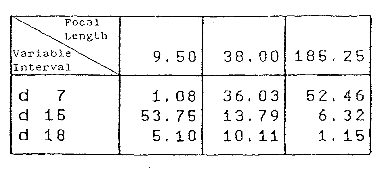
- In the numerical embodiment 4 shown in Fig. 4, the second lens located closer to the image side than the insertion gap for the extender EX is used as a wobbling unit lens. In addition, the extender EX can be inserted in a space with d26 = 30 mm.
- In the numerical embodiment 4, the lens unit L4b located closer to the object side than the wobbling unit wo has a negative refractive power. In contrast to the numerical embodiment 1, since 4b is brought closer to the lower limit, a change in imaging magnification (conditional expression (2)) accompanying insertion of the extender EX takes a large value.
- Figs. 13 and 14 are aberration diagrams at the wide-angle end and telephoto end without insertion of the extender in the numerical embodiment 4. Fig. 22 is an aberration diagram at the wide-angle end with insertion of the extender.
-
Numerical Embodiment 5 f=9.50∼185.25 Fno:2.0∼2.85 2ω:60.1° ∼3.4° r 1= 622.723 d 1= 2.20 n 1=1.76168 ν 1= 27.5 r 2= 77.855 d 2= 12.34 n 2=1.48915 ν 2= 70.2 r 3= -323.998 d 3= 7.78 r 4= 86.923 d 4= 8.66 n 3=1.62032 ν 3= 63.4 r 5= -1529.464 d 5= 0.15 r 6= 64.688 d 6= 6.06 n 4=1.73234 ν 4= 54.7 r 7= 134.784 d 7=Variable r 8= 111.445 d 8= 0.80 n 5=1.88814 ν 5= 40.8 r 9= 16.812 d 9= 4.65 r10= -47.842 d10= 0.70 n 6=1.82017 ν 6= 46.6 r11= 33.779 d11= 2.24 r12= 28.944 d12= 5.20 n 7=1.81264 ν 7= 25.4 r13= -29.192 d13= 0.54 r14= -24.664 d14= 0.70 n 8=1.79196 ν 8= 47.4 r15= 132.572 d15=Variable r16= -28.806 d16= 0.75 n 9=1.74679 ν 9= 49.3 r17= 37.218 d17= 3.81 n10=1.85501 ν10= 23.9 r18= 449.023 d18=Variable r19= ∞ (Stop) d19= 1.40 r20= -288.753 d20= 4.45 n11=1.66152 ν11= 50.9 r21= -27.952 d21= 0.20 r22= 64.233 d22= 7.14 n12=1.48915 ν12= 70.2 r23= -25.959 d23= 1.20 n13=1.83932 ν13= 37.2 r24= -72.322 d24= 30.00 r26= 47.982 d25= 5.34 n14=1.48915 ν14= 70.2 r26= -125.570 d26= 2.50 r27= -96.426 d27= 1.20 n15=1.69979 ν15= 55.5 r28= 191.570 d28= 5.00 r29= -122.237 d29= 1.20 n16=1.88815 ν16= 40.8 r30= 1090.682 d30= 5.32 n17=1.48915 ν17= 70.2 r31= -30.494 d31= 0.15 r32= 106.004 d32= 1.20 n18=1.80642 ν18= 35.0 r33= 34.262 d33= 2.67 r34= 47.028 d34= 8.44 n19=1.50349 ν19= 56.4 r35= -20.185 d35= 1.20 n20=1.88815 ν20= 40.8 r36= -76.910 d36= 2.56 r37= 90.563 d37= 4.83 n21=1.66152 ν21= 50.9 r38= -49.369 d38= 4.00 r39= ∞ d39= 30.00 n22=1.60718 ν22= 38.0 r40= ∞ d40= 16.20 n23=1.51825 ν23= 64.2 r41= ∞ Extender Portion d24= 1.60 r25= 1327.342 d25= 2.96 n14=1.52033 ν14= 58.9 r26= -65.631 d26= 0.20 r27= 19.393 d27= 5.95 n15=1.52033 ν15= 58.9 r28= 92.908 d28= 0.20 r29= 16.264 d29= 5.90 n.6=1.51825 ν16= 64.1 r30= 88.347 d30= 0.80 n17=1.85501 ν17= 23.9 r31= 10.562 d31= 6.15 r32= -61.482 d32= 0.90 n18=1.64254 ν18= 60.1 r33= 11.288 d33= 2.81 n19=1.85501 ν19= 23.9 r34= 24.985 d34= 2.54 
- In the numerical embodiment 5 shown in Fig. 5, the second lens located closer to the image side than the insertion gap for the extender EX is used as a wobbling unit lens, and the extender EX can be inserted/removed in/from a space with d24 = 30 mm. In the numerical embodiment 5, the wobbling unit wo has a negative refractive power.
- In the numerical embodiment 5, 4b is brought closer to the upper limit, a change in imaging magnification (conditional expression (2)) accompanying insertion/removal of the extender takes a large value.
- In this numerical embodiment, the unit L4c is integrally moved to allow macro photographing and flange-back adjustment.
- Figs. 15 and 16 are aberration diagrams at the wide-angle end and telephoto end without insertion of the extender in the numerical embodiment 5. Fig. 23 is an aberration diagram at the wide-angle end with insertion of the extender.
-
Numerical Embodiment 6 f =10.0∼440.0 Fno:1.75∼3.0 2ω:57.6° ∼1.4° r 1= 370.170 d 1= 5.50 n 1=1.72311 ν 1= 29.6 r 2= 179.081 d 2= 0.47 r 3= 177.086 d 3= 21.52 n 2=1.43496 ν 2= 95.1 r 4= -738.246 d 4= 0.30 r 5= 179.834 d 5= 16.94 n 3=1.43496 ν 3= 95.1 r 6=-18484.366 d 6= 0.30 r 7= 136.803 d 7= 11.61 n 4=1.49845 ν 4= 81.6 r 8= 299.938 d 8=Variable r 9= 2064.706 d 9= 2.00 n 5=1.32017 ν 5= 46.6 r10= 56.194 d10= 4.93 r11= -200.836 d11= 1.80 n 6=1.77621 ν 6= 49.6 r12= 58.527 d12= 5.92 r13= -70.671 d13= 1.80 n 7=1.82017 ν 7= 46.6 r14= 47.059 d14= 7.61 n 8-1.93306 ν 8= 21.3 r15= -741.457 d15=Variable r16= -3286.091 d16= 6.09 n 9=1.50014 ν 9= 65.0 r17= -100.506 d17= 0.30 r18= 101.499 d18= 2.50 n10=1.65223 ν10= 33.8 r19= 80.299 d19= 11.32 n11=1.59143 ν11= 61.2 r20= -160.387 d20= 0.20 r21= 153.942 d21= 11.39 n12=1.60548 ν12= 60.7 r22= -78.774 d22= 2.50 n13=1.85501 ν13= 23.9 r23= -210.812 d23= 0.20 r24= 126.384 d24= 7.22 n14=1.48915 ν14= 70.2 r25= -511.899 d25=Variable r26= ∞ (Stop) d26= 3.20 r27= -61.995 d27= 1.80 n15=1.79013 ν15= 44.2 r28= 27.859 d28= 5.10 n16=1.81265 ν16= 25.4 r29= 95.165 d29= 5.38 r30= -36.960 d30= 1.60 n17=1.73234 ν17= 54.7 r31= 61.070 d31= 13.54 n18=1.69911 ν18= 39.2 r32= -42.108 d32= 10.38 r33= -161.981 d33= 6.30 n19=1.77621 ν19= 49.6 r34= -78.477 d34= 8.00 r35= 122.002 d35= 6.76 n20=1.48915 ν20= 70.2 r36= -60.053 d36= 3.00 r37= -261.658 d37= 2.20 n21-1.83932 ν21= 37.2 r38= 35.540 d38= 6.45 n22=1.50349 ν22= 56.4 r39= -139.587 d39= 2.65 r40= 638.436 d40= 5.93 n23=1.55099 ν23= 45.8 r41= -36.259 d41= 2.20 n24=1.81265 ν24= 25.4 r42= -97.233 d42= 0.20 r43= 101.200 d43= 5.15 n25=1.51977 ν25= 52.4 r44= -76.148 d44= 5.00 r45= ∞ d45= 50.00 n26=1.51825 ν26= 64.2 r46= ∞ - R = -1.01x10+2 , B = 5.06x10⁻⁸, C=4.27x10⁻¹² , D=2.70x10⁻¹⁴ , E=-2.56x10⁻¹⁷
Extender Portion d29= 9.29 r30= 51.233 d30= 6.13 n17=1.48915 ν17= 70.2 r31= -81.169 d31= 6.03 r32= 2003.963 d32= 5.29 n18=1.69979 ν18= 55.5 r33= -41.347 d33= 1.20 n19=1.85501 ν19= 23.9 r34= -86.830 d34= 0.85 r35= 49.570 d35= 1.40 n20=1.82017 ν20= 46.6 r36= 33.003 d36= 4.09 r37= -672.531 d37= 0.90 n21=1.82017 ν21= 46.6 r38= 17.840 d38= 4.10 n22=1.85501 ν22= 23.9 r39= 35.205 d39= 5.92 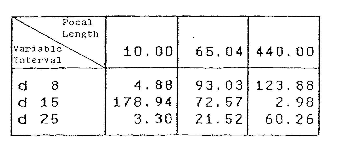
- In the numerical embodiment 6 shown in Fig. 6, the sixth lens of the fourth unit from the image side is used as a wobbling unit lens, and the extender EX can be inserted/removed in/from a space with d34 = 45.2 mm.
- In the numerical embodiment 6, unlike in the numerical embodiments 1 to 5, an optical system is placed in the space in the fourth unit, in/from which the extender EX is inserted/removed, instead of setting a large space as an air gap at the time of 1x, and the optical system at the time of 1x is retracted (ejected) from the optical axis upon insertion of the extender.
- In this case as well, by setting the refractive power of the lens unit L4b within an appropriate range, an image height change ratio can be suppressed low regardless of the insertion/removal of the extender EX.
- In each numerical embodiment described above, the lens units located closer to the object side than the extender EX are fixed regardless of insertion/removal of the extender EX. By placing an optical system at the time of 1x and insertion of the extender, the degree of freedom in design increases, and high optical performance with a low image height change ratio can be realized.
- Figs. 17 and 18 are aberration diagrams at the wide-angle end and telephoto end without insertion of the extender in the numerical embodiment 6. Fig. 24 is an aberration diagram at the wide-angle end with insertion the extender.

- As described above, according to this embodiment, there is provided a zoom lens suitable for a TV camera, video camera, or the like, which has a large aperture of an F-number of about 1.8 to 2 and a high magnification ratio of 10× or more, exhibits a small change in imaging magnification accompanying wobbling regardless of insertion/removal of an optical system such as the extender EX in the relay unit, and has excellent optical performance throughout the entire magnification change range.
- A photographing system (TV camera system) using one of the zoom lenses in the numerical embodiments 1 to 6 as a photographing optical system will be described next with reference to Fig. 25.
- Referring to Fig. 25, this photographing system includes a photographing system body 106 including lenses, a photographing optical system 101 formed by one of the zoom lenses in the numerical embodiments 1 to 6, a glass block 102 corresponding to a filter or color separation prism, an image pickup element 103 such as a CCD for receiving an object image formed by the photographing optical system 101, and CPUs 104 and 105 for controlling the photographing system and lenses.
- By using one of the zoom lenses in the numerical embodiments 1 to 6 for a photographing system such as a TV camera, a photographing system can be realized, in which a change in imaging magnification upon slight amplitude driving of a wobbling unit wo in the optical axis direction for autofocus operation is small regardless of whether an extender EX is inserted/removed, i.e., poor screen display can be prevented.
- The present invention is not limited to the zoom lenses shown in Figs. 1 to 6. A lens unit other than the lens units shown in Figs. 1 to 6 may be added to the zoom lens.
- For example, as shown in Fig. 26, the lens unit may be constituted by I, II, III, IV, and V units. The same reference numerals as in Fig. 26 denote the same parts in Fig. 25.
- As has been described above, according to the present invention, a change in imaging magnification caused when the wobbling unit is slightly amplitude-driven in the optical axis direction can be suppressed small regardless of the insertion/removal of the magnification changing optical unit.
- Note that if conditional expression (1) is satisfied, a change in imaging magnification accompanying wobbling without insertion of the magnification changing optical unit can be sufficiently suppressed small.
- If conditional expression (2) is satisfied, a change in imaging magnification accompanying wobbling with insertion of the magnification changing optical unit can be sufficiently suppressed small.
- If conditional expression (3) is satisfied, a change in incident angle on the wobbling unit upon insertion/removal of the magnification changing optical unit can be made small. This makes it possible to reduce a change in imaging magnification more reliably.
- Note that if the wobbling unit is placed closest to the image side in the fourth unit, a reduction in the size and weight of the wobbling unit to be slightly amplitude-driven can be attained.
- If this system is designed to retract part of the fourth unit from the optical axis by inserting the magnification changing optical unit, a large space for the insertion of the magnification changing optical unit can be ensured while a reduction in the overall size of the zoom lens is attained. This makes it possible to suppress a deterioration in optical performance at the time of insertion of the magnification changing optical unit.
Claims (12)
- A zoom lens in/from which a magnification changing optical unit for changing an overall focal length of said zoom lens can be inserted/removed, characterized in that a wobbling unit which can be slightly amplitude-driven in an optical axis direction to detect a best imaging position is placed closer to an image side than an insertion position of said magnification changing optical unit.
- A lens according to claim 1, wherein said zoom lens sequentially includes, from an object side, a first unit which is fixed in magnification changing operation and has a positive refractive power, a second unit which moves in the optical axis direction in magnification changing operation and has a negative refractive power, a third unit for correcting an image plane fluctuation accompanying magnification changing operation, and a fourth unit having a positive refractive power for imaging, and a magnification changing optical unit which changes the overall focal length of said zoom lens can be inserted/removed in/from said fourth unit.
- A lens according to claim 2, wherein a light amount adjustment stop is placed closer to the object side than said fourth unit.
- A lens according to claim 3, wherein when said wobbling unit is placed in said fourth unit and amplitude-driven to make an amplitude halfwidth of a backfocus change amount become 1/2 a depth of focus,
- A lens according to claim 3 or 4, wherein when said wobbling unit is placed in said fourth unit amplitude-driven to make an amplitude halfwidth of a backfocus change amount become 1/2 a depth of focus,
- A lens according to any one of claims 1 to 5, wherein in said fourth unit,
- A lens according to any one of claims 1 to 6, wherein said wobbling unit is placed closest to the image side in said fourth unit.
- A lens according to any one of claims 1 to 7, wherein part of said fourth unit is retracted on the optical axis by inserting said magnification changing optical unit.
- A lens according to any one of claims 1 to 8, wherein an optical system for macro photographing and flange-back adjustment is placed closer to the image side than said wobbling unit in said fourth unit, and said optical system can integrally move in macro photographing and flange-back adjustment.
- A lens according to any one of claims 1 to 9, wherein an optical system for macro photographing and flange-back adjustment is placed closer to the image side than said wobbling unit in said fourth unit, and said optical system comprises a lens unit fixed in macro photographing and flange-back adjustment and a lens unit which can move in macro photographing and flange-back adjustment.
- A lens according to any one of claims 1 to 10, wherein an amplitude halfwidth of the wobbling unit before/after insertion of said magnification changing optical unit is
- A photographing system comprising said zoom lens defined in any one of claims 1 to 10 and a camera on which said zoom lens is mounted.
Applications Claiming Priority (4)
| Application Number | Priority Date | Filing Date | Title |
|---|---|---|---|
| JP2000403516 | 2000-12-28 | ||
| JP2000403516 | 2000-12-28 | ||
| JP2001384439A JP3950685B2 (en) | 2000-12-28 | 2001-12-18 | Zoom lens and shooting system |
| JP2001384439 | 2001-12-18 |
Publications (2)
| Publication Number | Publication Date |
|---|---|
| EP1220001A1 true EP1220001A1 (en) | 2002-07-03 |
| EP1220001B1 EP1220001B1 (en) | 2003-10-08 |
Family
ID=26607259
Family Applications (1)
| Application Number | Title | Priority Date | Filing Date |
|---|---|---|---|
| EP01310870A Expired - Lifetime EP1220001B1 (en) | 2000-12-28 | 2001-12-24 | Zoom lens and photographing system |
Country Status (4)
| Country | Link |
|---|---|
| US (1) | US6965481B2 (en) |
| EP (1) | EP1220001B1 (en) |
| JP (1) | JP3950685B2 (en) |
| DE (1) | DE60100933T2 (en) |
Cited By (4)
| Publication number | Priority date | Publication date | Assignee | Title |
|---|---|---|---|---|
| EP1530070A1 (en) * | 2003-11-04 | 2005-05-11 | Canon Kabushiki Kaisha | Image-taking lens system and image-taking system |
| EP1530072A1 (en) * | 2003-11-07 | 2005-05-11 | Canon Kabushiki Kaisha | Zoom lens with insertable focal length converter and image taking system |
| US6965481B2 (en) * | 2000-12-28 | 2005-11-15 | Canon Kabushiki Kaisha | Zoom lens and photographing system |
| EP1708494A4 (en) * | 2004-01-19 | 2009-08-12 | Panasonic Corp | IMAGING DEVICE AND IMAGING METHOD |
Families Citing this family (17)
| Publication number | Priority date | Publication date | Assignee | Title |
|---|---|---|---|---|
| JP4508604B2 (en) * | 2003-11-06 | 2010-07-21 | キヤノン株式会社 | Zoom lens and imaging apparatus having the same |
| JP2005321545A (en) * | 2004-05-07 | 2005-11-17 | Sony Corp | Imaging device |
| JP4838557B2 (en) * | 2005-09-12 | 2011-12-14 | キヤノン株式会社 | Zoom lens and imaging apparatus having the same |
| JP2008039918A (en) * | 2006-08-02 | 2008-02-21 | Olympus Corp | Microscopic optical system and microscopic observation method |
| JP5448502B2 (en) * | 2009-03-02 | 2014-03-19 | キヤノン株式会社 | Adapter optical system and imaging optical system having the same |
| JP5443185B2 (en) * | 2010-01-29 | 2014-03-19 | 株式会社シグマ | Large-aperture telephoto zoom lens with anti-vibration function |
| JP5537186B2 (en) * | 2010-02-24 | 2014-07-02 | オリンパスイメージング株式会社 | Attachment lens device and imaging device including the same |
| JP5717988B2 (en) * | 2010-06-07 | 2015-05-13 | オリンパス株式会社 | Variable magnification optical system and imaging apparatus using the same |
| JP5241779B2 (en) * | 2010-07-26 | 2013-07-17 | キヤノン株式会社 | Zoom lens and imaging apparatus having the same |
| CN103782217B (en) | 2011-08-30 | 2016-05-18 | 富士胶片株式会社 | Variable magnification optical system and imaging device |
| US9478692B1 (en) | 2012-05-10 | 2016-10-25 | Lackheed Martin Corporation | X-ray multiband emission and conversion |
| US9432587B1 (en) | 2012-05-10 | 2016-08-30 | Lockheed Martin Corporation | Near-field enhanced photon conversion |
| US9521336B1 (en) * | 2012-05-10 | 2016-12-13 | Lockheed Martin Corporation | Multi-spectral photon converting imaging apparatus |
| JP6251009B2 (en) * | 2013-11-12 | 2017-12-20 | キヤノン株式会社 | Zoom lens and imaging apparatus having the same |
| JP6618268B2 (en) * | 2015-04-07 | 2019-12-11 | キヤノン株式会社 | Imaging device |
| CN106773032A (en) * | 2016-12-02 | 2017-05-31 | 中国航空工业集团公司洛阳电光设备研究所 | A kind of big visual field infrared optical system of zoom ratio three of ultrashort compact |
| JP7543007B2 (en) * | 2020-07-06 | 2024-09-02 | キヤノン株式会社 | Optical Systems and Instruments |
Citations (6)
| Publication number | Priority date | Publication date | Assignee | Title |
|---|---|---|---|---|
| JPH02210975A (en) * | 1989-02-10 | 1990-08-22 | Hitachi Ltd | video camera autofocus device |
| JPH0478808A (en) * | 1990-07-20 | 1992-03-12 | Canon Inc | rear focus zoom lens |
| US5138492A (en) * | 1990-07-20 | 1992-08-11 | Canon Kabushiki Kaisha | Rear-focus type zoom lens suppressing fluctuation of aberration |
| US5521758A (en) * | 1992-06-19 | 1996-05-28 | Canon Kabushiki Kaisha | Variable-magnification optical system capable of image stabilization |
| US5758206A (en) * | 1996-01-12 | 1998-05-26 | Canon Kabushiki Kaisha | Lens position control device for a zoom lens |
| US5771123A (en) * | 1996-02-27 | 1998-06-23 | Canon Kabushiki Kaisha | Zoom lens having image stabilizing function |
Family Cites Families (2)
| Publication number | Priority date | Publication date | Assignee | Title |
|---|---|---|---|---|
| US5786853A (en) * | 1994-04-12 | 1998-07-28 | Canon Kabushiki Kaisha | Lens control device |
| JP3950685B2 (en) * | 2000-12-28 | 2007-08-01 | キヤノン株式会社 | Zoom lens and shooting system |
-
2001
- 2001-12-18 JP JP2001384439A patent/JP3950685B2/en not_active Expired - Fee Related
- 2001-12-24 DE DE60100933T patent/DE60100933T2/en not_active Expired - Lifetime
- 2001-12-24 EP EP01310870A patent/EP1220001B1/en not_active Expired - Lifetime
- 2001-12-27 US US10/032,767 patent/US6965481B2/en not_active Expired - Fee Related
Patent Citations (6)
| Publication number | Priority date | Publication date | Assignee | Title |
|---|---|---|---|---|
| JPH02210975A (en) * | 1989-02-10 | 1990-08-22 | Hitachi Ltd | video camera autofocus device |
| JPH0478808A (en) * | 1990-07-20 | 1992-03-12 | Canon Inc | rear focus zoom lens |
| US5138492A (en) * | 1990-07-20 | 1992-08-11 | Canon Kabushiki Kaisha | Rear-focus type zoom lens suppressing fluctuation of aberration |
| US5521758A (en) * | 1992-06-19 | 1996-05-28 | Canon Kabushiki Kaisha | Variable-magnification optical system capable of image stabilization |
| US5758206A (en) * | 1996-01-12 | 1998-05-26 | Canon Kabushiki Kaisha | Lens position control device for a zoom lens |
| US5771123A (en) * | 1996-02-27 | 1998-06-23 | Canon Kabushiki Kaisha | Zoom lens having image stabilizing function |
Non-Patent Citations (2)
| Title |
|---|
| PATENT ABSTRACTS OF JAPAN vol. 014, no. 507 (E - 0998) 6 November 1990 (1990-11-06) * |
| PATENT ABSTRACTS OF JAPAN vol. 016, no. 296 (P - 1378) 30 June 1992 (1992-06-30) * |
Cited By (6)
| Publication number | Priority date | Publication date | Assignee | Title |
|---|---|---|---|---|
| US6965481B2 (en) * | 2000-12-28 | 2005-11-15 | Canon Kabushiki Kaisha | Zoom lens and photographing system |
| EP1530070A1 (en) * | 2003-11-04 | 2005-05-11 | Canon Kabushiki Kaisha | Image-taking lens system and image-taking system |
| US7423687B2 (en) | 2003-11-04 | 2008-09-09 | Canon Kabushiki Kaisha | Image-taking lens system and image-taking system |
| EP1530072A1 (en) * | 2003-11-07 | 2005-05-11 | Canon Kabushiki Kaisha | Zoom lens with insertable focal length converter and image taking system |
| EP1708494A4 (en) * | 2004-01-19 | 2009-08-12 | Panasonic Corp | IMAGING DEVICE AND IMAGING METHOD |
| US7847837B2 (en) | 2004-01-19 | 2010-12-07 | Panasonic Corporation | Imagine pickup device and imagine pickup method |
Also Published As
| Publication number | Publication date |
|---|---|
| JP3950685B2 (en) | 2007-08-01 |
| US6965481B2 (en) | 2005-11-15 |
| DE60100933D1 (en) | 2003-11-13 |
| US20020149692A1 (en) | 2002-10-17 |
| DE60100933T2 (en) | 2004-08-12 |
| EP1220001B1 (en) | 2003-10-08 |
| JP2002258157A (en) | 2002-09-11 |
Similar Documents
| Publication | Publication Date | Title |
|---|---|---|
| EP1220001B1 (en) | Zoom lens and photographing system | |
| EP2026113B1 (en) | Zoom lens of the telephoto type having four lens groups | |
| JP5142829B2 (en) | Zoom lens and imaging apparatus having the same | |
| EP0751414B1 (en) | Zoom lens | |
| US6084721A (en) | Zoom lens | |
| JP3486560B2 (en) | Zoom lens | |
| JP5006575B2 (en) | Zoom lens and imaging apparatus using the same | |
| JP2009175324A5 (en) | ||
| EP1092999B1 (en) | Zoom lens and photographing apparatus having the same | |
| EP2023178B1 (en) | Zoom lens of the telephoto type and having four lens groups | |
| JP5006634B2 (en) | Zoom lens and imaging apparatus having the same | |
| JPH06242378A (en) | Zoom lens | |
| US7236305B2 (en) | Zoom lens and image pickup apparatus having the same | |
| JPH10161026A (en) | Zoom lens | |
| JP3102200B2 (en) | Zoom lens | |
| JP4545849B2 (en) | Variable magnification optical system | |
| EP1148369B1 (en) | Zoom lens and photographing apparatus using the same | |
| JP4677210B2 (en) | Zoom lens and image pickup apparatus using the same | |
| JP4717399B2 (en) | Zoom lens and imaging apparatus having the same | |
| JP4630578B2 (en) | Zoom lens and imaging apparatus having the same | |
| JP2005215518A (en) | Zoom lens and imaging apparatus using the same | |
| JP4865218B2 (en) | Zoom lens and imaging apparatus having the same | |
| JPH0763992A (en) | Zoom lens and image pickup apparatus using the same | |
| JP3183047B2 (en) | Zoom lens | |
| JPH06250086A (en) | Zoom lens |
Legal Events
| Date | Code | Title | Description |
|---|---|---|---|
| PUAI | Public reference made under article 153(3) epc to a published international application that has entered the european phase |
Free format text: ORIGINAL CODE: 0009012 |
|
| AK | Designated contracting states |
Kind code of ref document: A1 Designated state(s): AT BE CH CY DE DK ES FI FR GB GR IE IT LI LU MC NL PT SE TR |
|
| AX | Request for extension of the european patent |
Free format text: AL;LT;LV;MK;RO;SI |
|
| 17P | Request for examination filed |
Effective date: 20021113 |
|
| GRAH | Despatch of communication of intention to grant a patent |
Free format text: ORIGINAL CODE: EPIDOS IGRA |
|
| RIC1 | Information provided on ipc code assigned before grant |
Ipc: 7G 02B 27/64 B Ipc: 7G 02B 15/14 A |
|
| RIC1 | Information provided on ipc code assigned before grant |
Ipc: 7G 02B 15/14 A Ipc: 7G 02B 27/64 B |
|
| AKX | Designation fees paid |
Designated state(s): DE FR GB NL |
|
| GRAS | Grant fee paid |
Free format text: ORIGINAL CODE: EPIDOSNIGR3 |
|
| GRAA | (expected) grant |
Free format text: ORIGINAL CODE: 0009210 |
|
| AK | Designated contracting states |
Kind code of ref document: B1 Designated state(s): DE FR GB NL |
|
| REG | Reference to a national code |
Ref country code: GB Ref legal event code: FG4D |
|
| REG | Reference to a national code |
Ref country code: IE Ref legal event code: FG4D |
|
| REF | Corresponds to: |
Ref document number: 60100933 Country of ref document: DE Date of ref document: 20031113 Kind code of ref document: P |
|
| ET | Fr: translation filed | ||
| PLBE | No opposition filed within time limit |
Free format text: ORIGINAL CODE: 0009261 |
|
| STAA | Information on the status of an ep patent application or granted ep patent |
Free format text: STATUS: NO OPPOSITION FILED WITHIN TIME LIMIT |
|
| REG | Reference to a national code |
Ref country code: IE Ref legal event code: MM4A |
|
| 26N | No opposition filed |
Effective date: 20040709 |
|
| PGFP | Annual fee paid to national office [announced via postgrant information from national office to epo] |
Ref country code: GB Payment date: 20131217 Year of fee payment: 13 Ref country code: DE Payment date: 20131231 Year of fee payment: 13 |
|
| PGFP | Annual fee paid to national office [announced via postgrant information from national office to epo] |
Ref country code: NL Payment date: 20131216 Year of fee payment: 13 |
|
| PGFP | Annual fee paid to national office [announced via postgrant information from national office to epo] |
Ref country code: FR Payment date: 20131227 Year of fee payment: 13 |
|
| REG | Reference to a national code |
Ref country code: DE Ref legal event code: R119 Ref document number: 60100933 Country of ref document: DE |
|
| REG | Reference to a national code |
Ref country code: NL Ref legal event code: V1 Effective date: 20150701 |
|
| REG | Reference to a national code |
Ref country code: NL Ref legal event code: V1 Effective date: 20150701 |
|
| GBPC | Gb: european patent ceased through non-payment of renewal fee |
Effective date: 20141224 |
|
| REG | Reference to a national code |
Ref country code: FR Ref legal event code: ST Effective date: 20150831 |
|
| PG25 | Lapsed in a contracting state [announced via postgrant information from national office to epo] |
Ref country code: NL Free format text: LAPSE BECAUSE OF NON-PAYMENT OF DUE FEES Effective date: 20150701 |
|
| PG25 | Lapsed in a contracting state [announced via postgrant information from national office to epo] |
Ref country code: GB Free format text: LAPSE BECAUSE OF NON-PAYMENT OF DUE FEES Effective date: 20141224 Ref country code: DE Free format text: LAPSE BECAUSE OF NON-PAYMENT OF DUE FEES Effective date: 20150701 |
|
| PG25 | Lapsed in a contracting state [announced via postgrant information from national office to epo] |
Ref country code: FR Free format text: LAPSE BECAUSE OF NON-PAYMENT OF DUE FEES Effective date: 20141231 |