EP1219890A2 - A lamp unit, projector, and a method of assembling - Google Patents
A lamp unit, projector, and a method of assembling Download PDFInfo
- Publication number
- EP1219890A2 EP1219890A2 EP01310766A EP01310766A EP1219890A2 EP 1219890 A2 EP1219890 A2 EP 1219890A2 EP 01310766 A EP01310766 A EP 01310766A EP 01310766 A EP01310766 A EP 01310766A EP 1219890 A2 EP1219890 A2 EP 1219890A2
- Authority
- EP
- European Patent Office
- Prior art keywords
- reflector
- light source
- light
- source lamp
- lamp
- Prior art date
- Legal status (The legal status is an assumption and is not a legal conclusion. Google has not performed a legal analysis and makes no representation as to the accuracy of the status listed.)
- Withdrawn
Links
Images


Classifications
-
- F—MECHANICAL ENGINEERING; LIGHTING; HEATING; WEAPONS; BLASTING
- F21—LIGHTING
- F21V—FUNCTIONAL FEATURES OR DETAILS OF LIGHTING DEVICES OR SYSTEMS THEREOF; STRUCTURAL COMBINATIONS OF LIGHTING DEVICES WITH OTHER ARTICLES, NOT OTHERWISE PROVIDED FOR
- F21V19/00—Fastening of light sources or lamp holders
-
- F—MECHANICAL ENGINEERING; LIGHTING; HEATING; WEAPONS; BLASTING
- F21—LIGHTING
- F21V—FUNCTIONAL FEATURES OR DETAILS OF LIGHTING DEVICES OR SYSTEMS THEREOF; STRUCTURAL COMBINATIONS OF LIGHTING DEVICES WITH OTHER ARTICLES, NOT OTHERWISE PROVIDED FOR
- F21V29/00—Protecting lighting devices from thermal damage; Cooling or heating arrangements specially adapted for lighting devices or systems
- F21V29/50—Cooling arrangements
- F21V29/60—Cooling arrangements characterised by the use of a forced flow of gas, e.g. air
- F21V29/67—Cooling arrangements characterised by the use of a forced flow of gas, e.g. air characterised by the arrangement of fans
-
- H—ELECTRICITY
- H04—ELECTRIC COMMUNICATION TECHNIQUE
- H04N—PICTORIAL COMMUNICATION, e.g. TELEVISION
- H04N9/00—Details of colour television systems
- H04N9/12—Picture reproducers
- H04N9/31—Projection devices for colour picture display, e.g. using electronic spatial light modulators [ESLM]
- H04N9/3102—Projection devices for colour picture display, e.g. using electronic spatial light modulators [ESLM] using two-dimensional electronic spatial light modulators
- H04N9/3105—Projection devices for colour picture display, e.g. using electronic spatial light modulators [ESLM] using two-dimensional electronic spatial light modulators for displaying all colours simultaneously, e.g. by using two or more electronic spatial light modulators
-
- H—ELECTRICITY
- H04—ELECTRIC COMMUNICATION TECHNIQUE
- H04N—PICTORIAL COMMUNICATION, e.g. TELEVISION
- H04N9/00—Details of colour television systems
- H04N9/12—Picture reproducers
- H04N9/31—Projection devices for colour picture display, e.g. using electronic spatial light modulators [ESLM]
- H04N9/3141—Constructional details thereof
- H04N9/315—Modulator illumination systems
-
- F—MECHANICAL ENGINEERING; LIGHTING; HEATING; WEAPONS; BLASTING
- F21—LIGHTING
- F21W—INDEXING SCHEME ASSOCIATED WITH SUBCLASSES F21K, F21L, F21S and F21V, RELATING TO USES OR APPLICATIONS OF LIGHTING DEVICES OR SYSTEMS
- F21W2131/00—Use or application of lighting devices or systems not provided for in codes F21W2102/00-F21W2121/00
- F21W2131/40—Lighting for industrial, commercial, recreational or military use
Definitions
- a projector has been used for presentation at conference, scientific society and exhibition.
- Such projector modulates a light beam irradiated by a lamp unit in accordance with image information to form an optical image and to enlarge and project the optical image.
- the lamp unit includes a light source lamp having a light emitting portion irradiating the light beam, and a substantially conic (cup-shaped) reflector for reflecting the light beam from the light emitting portion.
- the light source lamp is directly fixed at the bottom of the reflector by cement etc. with the light emitting portion being disposed at substantially the same position as the focus of the reflector so that the light emitting portion and neighborhood thereof are accommodated in the reflector.
- the attachment is formed on the reflector as an optical component, considering the accuracy of the reflection surface of the reflector etc., it is difficult for the attachment to have the most appropriate shape for holding and fixing the light source lamp, i.e. a complicated shape, so that the light source lamp may not be sufficiently held.
- a lamp unit includes: a light source lamp having a light emitting portion; a reflector disposed with the light emitting portion and a fixing portion thereinside that reflects a light beam irradiated by the light emitting portion; and a fixing member to which fixes the fixing portion of the light source lamp and the reflector are fixed, the light source lamp and the reflector being respectively fixed to the fixing member in a mutually independent manner, and a portion of the light source lamp between the fixing portion and the light emitting portion being exposed to an outside of the reflector.
- the fixing member may be formed as an integrated member or, alternatively, may be divided in plural.
- the attachment structure (a structure corresponding to the attachment of the conventional reflector) having the most suitable shape for supporting and fixing the light source lamp can be easily formed on the fixing member, thereby sufficiently supporting the light source lamp.
- the portion between the light emitting portion and the fixing portion of the light source lamp in other words, the portion disposed adjacent to the light emitting portion and of which temperature is easily raised in lighting the light source lamp, is exposed to the outside of the reflector, thereby allowing the heat to escape from the portion. Accordingly, the portion can be easily cooled, so that the temperature of the light emitting portion can be prevented from becoming too high, thereby lengthening the life of the light source lamp.
- the portion remote from the light emitting portion (fixing portion) can be supported and fixed and the portion between the light emitting portion and the fixing portion can be exposed to the outside of the reflector.
- the light transmitting member of the lamp unit may be divided in plural parts. Since the light transmitting member is divided in plural, i.e. composed of, for instance, a plurality of small glass plates, when the temperature inside the reflector is raised in accordance with temperature increase of the light source lamp in lighting, the crack of the light transmitting member on account of thermal deformation and the crack of the light transmitting member caused by fissure generated in processing the insert hole on the light transmitting member can be prevented.
- the light transmitting member may preferably be fixed to the fixing member. Since the light transmitting member is fixed to the fixing member, the attachment process thereof can be facilitated as compared to an arrangement attaching the light transmitting member to the reflector.
- the fixing member may preferably comprise a holder to which the fixing portion of the light source lamp is fixed and held and an air circulation channel may preferably penetrate the holder. Since an air circulation channel is provided to the holder of the fixing member, the fixing portion of the light source lamp fixed and held by the holder can be efficiently cooled, thereby lengthening the life of the light source lamp. Since the air circulation channel is formed on the holder of the fixing member, the shape of the reflector can be prevented from being too complicated and the air circulation channel can be easily formed.
- the light source lamp and the reflector are respectively positioned relative to the fixing member, positioning freedom of the respective components can be enhanced as compared to the conventional lamp unit having a light source lamp integrally attached with the reflector, thereby facilitating to enhance the illumination of the lamp unit.
- Fig. 1 schematically shows an optical unit 4 used in a projector 1 according to an embodiment of the present invention.
- the optical unit 4 optically processes the light beam irradiated by the light source to form an optical image corresponding to the image information, which includes an integrator illuminating optical system 41, a color separating optical system 42, a relay optical system 43, an electric optical device 44, a cross dichroic prism 45 and a projection lens 46.
- the integrator illuminating optical system 41 is an optical system for illuminating the image formation areas of the three liquid crystal panels 441 (respectively represented as liquid crystal panels 441R, 441G and 441B for each color light of red, green and blue), which includes a lamp unit 10, a UV filter 418, a first lens array 414, a second lens array 416, a polarization converter 415, a superimposing lens 419 and a reflection mirror 424.
- the lamp unit 10 has a light source lamp 11 as a radial light source for emitting radial light beam, a reflector 12 for reflecting the radial light emitted by the light source lamp ii and a below-described lamp housing 13 (sec Fig 2 et seq.) as a fixing member.
- a halogen lamp, a metal halide lamp, or a high-pressure mercury lamp is often used as the light source lamp 11.
- a parabolic mirror is used as the reflector 12.
- the structure of the lamp unit 10 will be described below in detail.
- the first lens array 414 has a matrix arrangement of lenses 414A having substantially rectangular profile viewed from optical axis direction.
- the respective lenses 414A split the beam emitted from the light source lamp 11 and passed the CV filter 418 into a plurality of partial light beams.
- the profile of the respective lenses 414A is approximately similar to the configuration of the image formation area of the liquid crystal panel 441. For instance, when the aspect ratio (ratio of horizontal and vertical dimensions) of the liquid crystal panels 441 is 4:3, the aspect ratio of the respective lenses is also set as 4:3.
- the second lens array 416 has approximately the same arrangement as the first lens array 414, where lenses 416A are disposed in matrix.
- the second lens array 416 focuses the image from the respective lenses 414A of the first lens array 414 onto the liquid crystal panel 441 as well as the superimposing lens 419.
- the polarization converter 415 is disposed between the second lens array 416 and the superimposing lens 419 for converting the light from the second lens array 416 to a single polarized light in order to enhance utilization efficiency of the light in the electric optical device 44.
- the respective partial light converted into single polarized light by the polarization converter 415 is substantially superimposed on the liquid crystal panels 441R, 441G and 441B of the electric optical device 44 by the superimposing lens 419. Since the projector 1 (the electric optical device 44) of the present embodiment using a liquid crystal panel 441 for modulating polarized light can use only single polarized light, approximately half of the light from the light source lamp 11 emitting random polarization light of other type cannot be utilized.
- the polarization converter 415 by using the polarization converter 415, all of the light emitted by the light source lamp 11 is converted into single polarized light to enhance utilization efficiency of the light in the electric optical device 44.
- polarization converter 415 is disclosed in, for instance, Japanese Patent Laid-Open publication No. Hei 8-304739.
- the color separating optical system 42 has two dichroic mirrors 421 and 422 and a reflection mirror 423, where the dichroic mirrors 421 and 422 separate the plurality of partial light beam irradiated by the integrator illuminating optical system 41 into three color lights of red, green and blue.
- the relay optical system 43 includes an incident-side lens 431, a relay lens 433 and reflection mirrors 432 and 434, which introduces blue light of the color lights separated by the color separating optical system 42 into the liquid crystal panel 441B.
- the blue color light component and the green light component of the light beam irradiated by the integrator illuminating optical system 41 are reflected by the dichroic mirror 421 of the color separating optical system 42 and the red color light component transmits through the dichroic mirror 421.
- the red color light transmitted through the dichroic mirror 421 is reflected by the reflection mirror 423 to reach to the liquid crystal panci 441R for red-color through a field lens 417.
- the field lens 417 converts the respective partial light beam emitted through the second lens array 416 into a light beam parallel to central axis thereof (main beam).
- the field lenses 417 provided in front of the other liquid crystal panels 441G and 441B function in the same manner.
- the green light is reflected by the dichroic mirror 422 to reach the liquid crystal panel 441G for green color through the field lens 417.
- the blue color transmits through the dichroic mirror 422 to pass the relay optical system 43 and reach the liquid crystal panel 441B for blue color through the field lens 417.
- the relay optical system 43 is used for the blue color in order to prevent decrease in light utilization etliciency on account of light diffusion, because the length of the optical path of the blue color light is longer than the length of the optical path of the other color lights, in other words, in order to directly transmit the partial light beam 'incident on the incident-side lens 431 to the field lens 417.
- the electric optical device 44 has the liquid crystal panels 441R, 441G and 441B as three optical modulators which, for instance, use a polysilicon TFT as switching element.
- the color lights separated by the color-separating optical systems 42 are modulated by the three crystal panels 441R, 441G and 441B in accordance with image information to form an optical image.
- the cross dichroic prism 45 combines the images modulated for respective color lights irradiated from the three liquid crystal panels 441R, 441G and 441B to form a color image.
- a dielectric multilayerfilm for reflecting red light and another dielectric multi-layer film for reflecting blue light are formed on the prism 45 along boundaries of the four right-angled prisms, the dielectric multilayers combining three color lights.
- the color image combined by the prism 45 is irradiated from the projection lens 46 and is enlarged and projected on a screen.
- Fig. 2 is a plan view of the above-described lamp unit 10
- Fig. 3 is a side elevational view thereof
- Fig. 4 is a vertical cross section thereof
- Fig. 5 is a front elevational view thereof
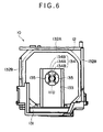
- Fig. 6 is a rear elevational view thereof
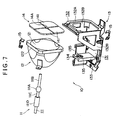
- Fig. 7 is an exploded perspective view thereof, respectively.
- the lamp unit 10 is accommodated in a casing (not shown) of a projector 1 and includes the light source lamp 11, the reflector 12 for aligning and irradiating the light beam irradiated by the light source lamp 11, and the lamp housing 13 as a fixing member on which the light source lamp 11 and the reflector 12 are mutually independently fixed.
- the light source lamp 11 is, for instance, a high-pressure mercury lamp and includes a glass light-emitting tube 111 and a pair of electrodes (not shown) accommodated inside the light-emitting tube 111.
- a light emitting portion 111A at the center of the light-emitting tube 111 is bulged relative to both sides 111B and 111C sandwiching the light emitting portion 111A.
- the pair of electrodes just oppose inside the light emitting portion 111A so that the light source lamp 11 is lit by the electric discharge between the pair of electrodes.
- an end of the first side 111B disposed on the left side in Fig. 4 penetrates a below-described protection glass plate 14 as a light transmitting member.
- a fixing portion 111D is formed on the second side 111C disposed on the right side in Fig. 4, through which the light-emitting tube 111 is supported and fixed to the lamp housing 13.
- the reflector 12 is formed in a cup-shape (approximately conic shape) of which inner surface is configured in an oval shape to be a reflection surface 121 as shown in Fig. 4.
- the reflector 12 is open to left side in the figure (light-emitting side) and the bottom is disposed on the right side in the figure.
- a flange 122 for attaching the reflector 12 to the lamp housing 13 is formed on the periphery of the opening of the reflector 12.
- An insert hole 123 for the light source lamp 11 to be inserted is formed at the center of the bottom of the reflector 12.
- the second side 111 C of the light-emitting tube 111 is inserted to the insert hole 123 while the light emitting portion 111A of the light-emitting tube 111 is disposed in the reflector 12.
- the disposition of the light-emitting tube 111 and the reflector 12 is adjusted so that the center of light emission in the light emitting portion 111A comes to the focus position of the reflector 12.
- the center of light emission refers to a position approximately at the center of an electric discharge channel generated between the pair of electrodes in the light-emitting tube 111.
- the reflector holder 132 has a body 132A formed in an approximately rectangular frame (Fig. 5 ), and two reinforcing members 132)3 vertically provided on both sides of the body 132A for reinforcing the body 132A and formed in an approximat triangle.
- the protection glass plate 14 is disposed at the back of the frame of the body 132A constituting the reflector holder 132.
- the protection glass plate 14 is divided in a plurality of pieces, i.e., for instance, in four approximate rectangular small glass plates 141.
- a through hole 14A is formed at the center of the protection glass plate 14, through which an end of the first end 11 IB of the light-emitting tube ill is penetrated.
- a peripheral portion of the opening of the reflector 12 is abutted to a backside of the protection glass plate 14 where the body 132A of the reflector holder 132 cannot be attached, so that a clip 15 holding the body 132A of the reflector holder 132, the protection glass plate 14 and the flange 122 of the reflector 12 pushes the flange 122 of the reflector 12 and the protection glass plate 14 against the body 132A of the reflector holder 132, thereby fixing the reflector 12 and the reflector holder 132 to the lamp housing 13.
- two clips 15 are used in the present embodiment, which are respectively disposed on the diagonal line of the protection glass plate 14.
- the protection glass plate 14 may be fixed on the reflector holder 132 using an adhesive as necessary.
- the light-emitting side of the reflector 12 is covered with the protection glass plate 14, so that, even when the light-emitting tube 111 is exploded, the fragments do not scatter to the outside of the reflector 12.
- the light source lamp holder 133 is formed in approximately planar C-shape (Fig. 2) and is located at a position remote from the bottom of the reflector 12 attached to the reflector holder 132 by a predetermined distance along a longitudinal direction of the light-emitting tube 111.
- the portion between the light emitting portion 111A of the light-emitting tube 111 disposed inside the reflector 12 and the fixing portion 111D of the light-emitting tube 11 ID supported by the light source lamp holder 133 is exposed to the outside of the reflector 12, so that the heat generated by the light source lamp 11 can be easily escaped therefrom and the portion can be cooled by cooling air.
- a support hole 134 for the fixing portion 111D of the light-emitting tube 111 to be inserted and fixed is formed at an approximate center of upper part of the light source lamp holder 133 (see Fig. 6).
- the support hole 134 is composed of an approximately circular insert hole 134A for the fixing portion 111D of the light-emitting tube 111 to be inserted and two approximately sectoral adhesive filling holes 134B continuing to the insert hole 134A for adhesive 134C such as cement (see Fig. 4) to be filled.
- the insert hole 134A and the adhesive filling hole 134B are continuously formed in a direction approximately orthogonal with the insertion direction of the light-emitting tube 111 to the insert hole 1 34A. Further, the two adhesive filling holes 134B are opposed sandwiching the insert hole 134A.
- two approximately sectoral air circulation holes 135 are formed around the insert hole 134A of the support hole 134.
- the two air circulation holes 135 are opposed sandwiching the insert hole 134A in the same manner as the two adhesive filling holes 134B.
- the air circulation holes 135 are not continued from the insert hole 134A unlike the adhesive filling hole 134B.
- the air circulation hole 135 By forming the air circulation hole 135 around the insert hole 135 for the light-emitting tube 111 to be held, the flow of the cooling air around the fixing portion 111D of the light-emitting tube 111 can be enhanced. In other words, since an air circulation channel can be formed around the fixing portion 111D of the light-emitting tube 111, the fixing portion 111D can be efficiently cooled.
- the protection glass plate 14 is attached to the reflector holder 132 of the lamp housing 13 by adhesive etc. Subsequently, the reflector 12 is disposed so that the opening thereof faces the protection glass plate IA atid the reflector 12 is attached to the reflector holder 132 by the clip 15 while the protection glass plate 14 is sandwiched by the reflector 12 and the reflector holder 132.
- the protection glass plate 14 may be fixed to the reflector holder 132 not by adhering and fixing the protection glass plate 14 to the reflector holder 132 but by sandwiching and holding the protection glass plate with the body 132A of the reflector holder 132 and the flange 122 of the reflector 12.
- the light source lamp 11 After attaching the protection glass plate 14 and the reflector 12 to the lamp housing 13, the light source lamp 11 is inserted to the insert hole 134A of the light source lamp holder 133 and the insert hole 12A of the reflector 12 in sequence. Then, after adjusting the center of light emission of the light source lamp 11 to the focus position of the reflector 12 to determine the position of the light source lamp 11 relative to the reflector 12, the adhesive filling hole 134B of the light source lamp holder 133 is filled to fix the light source lamp 11 to the light source lamp holder 133.
- the air circulation channel is formed around the fixing portion 111D of the light source lamp 11 by providing the air circulation hole 135 to the light source lamp holder 133, the air circulation channel may not necessarily be provided. However, the light source lamp 11 can be more efficiently cooled by providing the air circulation channel.
- the protection glass plate 14 is fixed to the lamp housing 13, the protection glass plate 14 may be directly fixed to the opening of the reflector as in the conventional arrangement.
- the protection glass plate 14 may be a separate type as in the above-described embodiment or, alternatively, may be an integrated type.
- the protection glass plate of the separate type is not restricted to be separated in four, but may be separated in two, three or more than four.
- the through hole 14A of the separate type projection glass plate 14 is formed in an approximate circular shape, a corner of the respective four small glass plate 141 may be cut in a triangle shape and the four small glass plates 141 may be combined so that cut portions are concentrated to the center of the protection glass plate 14, so that an approximate square through hole 14A is formed at the center of the protection glass plate 14. According to this arrangement, the through hole 14A can be easily formed to the protection glass plate 14 and crack generation can be prevented in processing the through hole 14A.
- the protection glass plate 14 for covering the light-emitting side of the reflector 12 is provided in the above-described embodiment, the lamp unit according to the present invention is not restricted to the arrangement and the protection glass plate may not be provided.
- the lamp housing 13 having integrated base 131, reflector holder 132 and the light source lamp holder 133 is used in the above-described embodiment, a separate type lamp housing having independent body of the base 131, the reflector holder 132 and the light source lamp holder 133 may be used.
- the light source lamp 11 can be detached from the base 131 together with the light source lamp holder 133 or the reflector 12 can be detached together with the reflector 132, so that the light source lamp 11 and the reflector 12 can be separated even after the lamp unit 10 is assembled.
- the light source lamp 11 can be solely exchanged when the life of the light source lamp 11 is exhausted. Further, the fixing portion 111D of the light source lamp 11 can be made unnecessary, and the first side 111C may be used as the fixing portion.
- the light source lamp 11 and the reflector 12 when illumination is found inferior after assembling the lamp unit 10, one of the light source lamp 11 and the reflector 12, the light source lamp for instance, is detached from the base 131 together with the light source lamp holder 133 and a new light source lamp holder 133 is attached to the base 133. Subsequently, a new light source lamp 11 is inserted to the support hole 134.of the light source lamp holder 133, which is fixed by cement etc. after positioning relative to the reflector 12.
- the relative position of the light source lamp 11 and the reflector 12 can be adjusted (alignment adjustment) after assembling the lamp unit 10, so that the illumination can be improved by exchanging one of the light source lamp 11 and the reflector 12.
- the projector of the present invention is not limited to those having a crystal liquid panel as an optical modulator, but may be those having an optical modulator of plasma element and micro mirror, having a reflective optical modulator for reflecting and modulating the incident light before emitting, and single-plate type, double-plate type and rear type.
- any arrangement is possible in implementing the present invention as long as the light beam irradiated from the source lamp is modulated in accordance with image information to form an optical image and the optical image is enlarged and projected by the projector.
Landscapes
- Engineering & Computer Science (AREA)
- General Engineering & Computer Science (AREA)
- Multimedia (AREA)
- Signal Processing (AREA)
- Projection Apparatus (AREA)
- Non-Portable Lighting Devices Or Systems Thereof (AREA)
Abstract
Description
- Conventionally, a projector has been used for presentation at conference, scientific society and exhibition. Such projector modulates a light beam irradiated by a lamp unit in accordance with image information to form an optical image and to enlarge and project the optical image.
- The lamp unit includes a light source lamp having a light emitting portion irradiating the light beam, and a substantially conic (cup-shaped) reflector for reflecting the light beam from the light emitting portion. The light source lamp is directly fixed at the bottom of the reflector by cement etc. with the light emitting portion being disposed at substantially the same position as the focus of the reflector so that the light emitting portion and neighborhood thereof are accommodated in the reflector.
- However, since an attachment for attaching and fixing the light source lamp has to be formed at the bottom of the above-described lamp unit, the configuration of the reflector becomes complicated and accuracy of the reflection surface is difficult to be improved.
- Further, since the attachment is formed on the reflector as an optical component, considering the accuracy of the reflection surface of the reflector etc., it is difficult for the attachment to have the most appropriate shape for holding and fixing the light source lamp, i.e. a complicated shape, so that the light source lamp may not be sufficiently held.
- A lamp unit according to the present invention includes: a light source lamp having a light emitting portion; a reflector disposed with the light emitting portion and a fixing portion thereinside that reflects a light beam irradiated by the light emitting portion; and a fixing member to which fixes the fixing portion of the light source lamp and the reflector are fixed, the light source lamp and the reflector being respectively fixed to the fixing member in a mutually independent manner, and a portion of the light source lamp between the fixing portion and the light emitting portion being exposed to an outside of the reflector.
- The fixing member may be formed as an integrated member or, alternatively, may be divided in plural.
- Since the light source lamp and the reflector are respectively independently fixed to the fixing member in the present invention, the attachment for attaching and fixing the light source lamp is not necessary to be formed on the reflector as an optical component. Accordingly, the shape of the reflector can be simplified and the accuracy of the reflection surface thereof can be easily improved, thereby enhancing illumination of the lamp unit.
- Since the light source lamp is attached to the fixing member, unlike the conventional arrangement where the shape of the attachment has to be determined considering accuracy of the reflector etc., the attachment structure (a structure corresponding to the attachment of the conventional reflector) having the most suitable shape for supporting and fixing the light source lamp can be easily formed on the fixing member, thereby sufficiently supporting the light source lamp.
- Since the portion between the light emitting portion and the fixing portion of the light source lamp, in other words, the portion disposed adjacent to the light emitting portion and of which temperature is easily raised in lighting the light source lamp, is exposed to the outside of the reflector, thereby allowing the heat to escape from the portion. Accordingly, the portion can be easily cooled, so that the temperature of the light emitting portion can be prevented from becoming too high, thereby lengthening the life of the light source lamp.
- Incidentally, since the light emitting portion and the neighborhood of the light emitting portion of the light source lamp are conventionally accommodated in the reflector, the temperature of the light source lamp is likely to become high when the lamp is lit and the light source lamp1s life is likely to be shortened.
- On the other hand, since the light source lamp is fixed to the fixing member in the present invention, the portion remote from the light emitting portion (fixing portion) can be supported and fixed and the portion between the light emitting portion and the fixing portion can be exposed to the outside of the reflector.
- A protective light transmitting member may preferably be provided on a light-emitting side of the reflector. Since the light-emitting side of the reflector is covered with the light transmitting member, even when the light source lamp is exploded, the fragment can be prevented from scattering to the outside of the reflector.
- The light transmitting member of the lamp unit may be divided in plural parts. Since the light transmitting member is divided in plural, i.e. composed of, for instance, a plurality of small glass plates, when the temperature inside the reflector is raised in accordance with temperature increase of the light source lamp in lighting, the crack of the light transmitting member on account of thermal deformation and the crack of the light transmitting member caused by fissure generated in processing the insert hole on the light transmitting member can be prevented.
- The light transmitting member may preferably be fixed to the fixing member. Since the light transmitting member is fixed to the fixing member, the attachment process thereof can be facilitated as compared to an arrangement attaching the light transmitting member to the reflector.
- Especially, since a troublesome process for attaching, for instance, adjacently-located small glass plates one by one is accompanied when the separate type light transmitting member is used, workability of the process can be improved by attaching the light transmitting member to the fixing member.
- In the lamp unit according to the present invention, the fixing member may preferably comprise a holder to which the fixing portion of the light source lamp is fixed and held and an air circulation channel may preferably penetrate the holder. Since an air circulation channel is provided to the holder of the fixing member, the fixing portion of the light source lamp fixed and held by the holder can be efficiently cooled, thereby lengthening the life of the light source lamp. Since the air circulation channel is formed on the holder of the fixing member, the shape of the reflector can be prevented from being too complicated and the air circulation channel can be easily formed.
- A method of assembling a lamp unit having a light source lamp and a reflector according to the present invention, includes the steps of: fixing one of the light source lamp and the reflector to a fixing member; positioning the other one of the light source lamp and the reflector relative to the one of the light source lamp and the reflector; and fixing the other one of the light source lamp and the reflector to the fixing member in a mutually independent manner.
- Since the light source lamp and the reflector are respectively positioned relative to the fixing member, positioning freedom of the respective components can be enhanced as compared to the conventional lamp unit having a light source lamp integrally attached with the reflector, thereby facilitating to enhance the illumination of the lamp unit.
- An example of the present invention will now be described in detail with reference to the accompanying drawings, in which:
- Fig. 1 is a plan view schematically showing an optical system of a projector according to an embodiment of the present invention;
- Fig. 2 is a plan view showing the lamp unit of the aforesaid embodiment;
- Fig. 3 is a side elevational view showing the lamp unit of the aforesaid embodiment;
- Fig. 4 is a cross section taken along IV-IV line of Fig. 4;
- Fig. 5 is a front elevational view showing the lamp unit of the aforesaid embodiment;
- Fig. 6 is a rear elevational view showing the lamp unit of the aforesaid embodiment; and,
- Fig. 7 is an exploded perspective view showing the lamp unit of the aforesaid embodiment.
-
- Fig. 1 schematically shows an
optical unit 4 used in aprojector 1 according to an embodiment of the present invention. - The
optical unit 4 optically processes the light beam irradiated by the light source to form an optical image corresponding to the image information, which includes an integrator illuminatingoptical system 41, a color separatingoptical system 42, a relayoptical system 43, an electricoptical device 44, a crossdichroic prism 45 and aprojection lens 46. - The integrator illuminating
optical system 41 is an optical system for illuminating the image formation areas of the three liquid crystal panels 441 (respectively represented as liquid crystal panels 441R, 441G and 441B for each color light of red, green and blue), which includes alamp unit 10, aUV filter 418, afirst lens array 414, asecond lens array 416, apolarization converter 415, asuperimposing lens 419 and areflection mirror 424. - The
lamp unit 10 has alight source lamp 11 as a radial light source for emitting radial light beam, areflector 12 for reflecting the radial light emitted by the light source lamp ii and a below-described lamp housing 13 (sec Fig 2 et seq.) as a fixing member. A halogen lamp, a metal halide lamp, or a high-pressure mercury lamp is often used as thelight source lamp 11. A parabolic mirror is used as thereflector 12. - The structure of the
lamp unit 10 will be described below in detail. - The
first lens array 414 has a matrix arrangement oflenses 414A having substantially rectangular profile viewed from optical axis direction. Therespective lenses 414A split the beam emitted from thelight source lamp 11 and passed theCV filter 418 into a plurality of partial light beams. The profile of therespective lenses 414A is approximately similar to the configuration of the image formation area of the liquid crystal panel 441. For instance, when the aspect ratio (ratio of horizontal and vertical dimensions) of the liquid crystal panels 441 is 4:3, the aspect ratio of the respective lenses is also set as 4:3. - The
second lens array 416 has approximately the same arrangement as thefirst lens array 414, wherelenses 416A are disposed in matrix. Thesecond lens array 416 focuses the image from therespective lenses 414A of thefirst lens array 414 onto the liquid crystal panel 441 as well as thesuperimposing lens 419. - The
polarization converter 415 is disposed between thesecond lens array 416 and thesuperimposing lens 419 for converting the light from thesecond lens array 416 to a single polarized light in order to enhance utilization efficiency of the light in the electricoptical device 44. - Specifically, the respective partial light converted into single polarized light by the
polarization converter 415 is substantially superimposed on the liquid crystal panels 441R, 441G and 441B of the electricoptical device 44 by thesuperimposing lens 419. Since the projector 1 (the electric optical device 44) of the present embodiment using a liquid crystal panel 441 for modulating polarized light can use only single polarized light, approximately half of the light from thelight source lamp 11 emitting random polarization light of other type cannot be utilized. - Accordingly, by using the
polarization converter 415, all of the light emitted by thelight source lamp 11 is converted into single polarized light to enhance utilization efficiency of the light in the electricoptical device 44. Incidentally,such polarization converter 415 is disclosed in, for instance, Japanese Patent Laid-Open publication No. Hei 8-304739. - The color separating
optical system 42 has twodichroic mirrors reflection mirror 423, where thedichroic mirrors optical system 41 into three color lights of red, green and blue. - The relay
optical system 43 includes an incident-side lens 431, arelay lens 433 andreflection mirrors optical system 42 into the liquid crystal panel 441B. - At this time, the blue color light component and the green light component of the light beam irradiated by the integrator illuminating
optical system 41 are reflected by thedichroic mirror 421 of the color separatingoptical system 42 and the red color light component transmits through thedichroic mirror 421. The red color light transmitted through thedichroic mirror 421 is reflected by thereflection mirror 423 to reach to the liquid crystal panci 441R for red-color through afield lens 417. Thefield lens 417 converts the respective partial light beam emitted through thesecond lens array 416 into a light beam parallel to central axis thereof (main beam). Thefield lenses 417 provided in front of the other liquid crystal panels 441G and 441B function in the same manner. - In the blue light and the green light reflected by the
dichroic mirror 421, the green light is reflected by thedichroic mirror 422 to reach the liquid crystal panel 441G for green color through thefield lens 417. On the other hand, the blue color transmits through thedichroic mirror 422 to pass the relayoptical system 43 and reach the liquid crystal panel 441B for blue color through thefield lens 417. Incidentally, the relayoptical system 43 is used for the blue color in order to prevent decrease in light utilization etliciency on account of light diffusion, because the length of the optical path of the blue color light is longer than the length of the optical path of the other color lights, in other words, in order to directly transmit the partial light beam 'incident on the incident-side lens 431 to thefield lens 417. - The electric
optical device 44 has the liquid crystal panels 441R, 441G and 441B as three optical modulators which, for instance, use a polysilicon TFT as switching element. The color lights separated by the color-separatingoptical systems 42 are modulated by the three crystal panels 441R, 441G and 441B in accordance with image information to form an optical image. - The cross
dichroic prism 45 combines the images modulated for respective color lights irradiated from the three liquid crystal panels 441R, 441G and 441B to form a color image. - Incidentally, a dielectric multilayerfilm for reflecting red light and another dielectric multi-layer film for reflecting blue light are formed on the
prism 45 along boundaries of the four right-angled prisms, the dielectric multilayers combining three color lights. The color image combined by theprism 45 is irradiated from theprojection lens 46 and is enlarged and projected on a screen. - Fig. 2 is a plan view of the above-described
lamp unit 10, Fig. 3 is a side elevational view thereof, Fig. 4 is a vertical cross section thereof, Fig. 5 is a front elevational view thereof, Fig. 6 is a rear elevational view thereof and Fig. 7 is an exploded perspective view thereof, respectively. - The
lamp unit 10 is accommodated in a casing (not shown) of aprojector 1 and includes thelight source lamp 11, thereflector 12 for aligning and irradiating the light beam irradiated by thelight source lamp 11, and thelamp housing 13 as a fixing member on which thelight source lamp 11 and thereflector 12 are mutually independently fixed. - The
light source lamp 11 is, for instance, a high-pressure mercury lamp and includes a glass light-emittingtube 111 and a pair of electrodes (not shown) accommodated inside the light-emittingtube 111. - A
light emitting portion 111A at the center of the light-emittingtube 111 is bulged relative to bothsides light emitting portion 111A. The pair of electrodes just oppose inside thelight emitting portion 111A so that thelight source lamp 11 is lit by the electric discharge between the pair of electrodes. - In the
sides tube 111, an end of thefirst side 111B disposed on the left side in Fig. 4 penetrates a below-describedprotection glass plate 14 as a light transmitting member. On the other hand, a fixingportion 111D is formed on thesecond side 111C disposed on the right side in Fig. 4, through which the light-emittingtube 111 is supported and fixed to thelamp housing 13. - The
reflector 12 is formed in a cup-shape (approximately conic shape) of which inner surface is configured in an oval shape to be areflection surface 121 as shown in Fig. 4. Thereflector 12 is open to left side in the figure (light-emitting side) and the bottom is disposed on the right side in the figure. - A
flange 122 for attaching thereflector 12 to thelamp housing 13 is formed on the periphery of the opening of thereflector 12. Aninsert hole 123 for thelight source lamp 11 to be inserted is formed at the center of the bottom of thereflector 12. - In the
reflector 12, thesecond side 111 C of the light-emittingtube 111 is inserted to theinsert hole 123 while thelight emitting portion 111A of the light-emittingtube 111 is disposed in thereflector 12. The disposition of the light-emittingtube 111 and thereflector 12 is adjusted so that the center of light emission in thelight emitting portion 111A comes to the focus position of thereflector 12. Incidentally, the center of light emission refers to a position approximately at the center of an electric discharge channel generated between the pair of electrodes in the light-emittingtube 111. - The
lamp housing 13 has a base 131 attached to a casing (not shown) of theprojector 1, areflector holder 132 and a lightsource lamp holder 133 as a holder of the present invention, thereflector holder 132 and the lightsource lamp holder 133 vertically provided on the base 131 in an opposing manner, thebase 131, thereflector holder 132 and the lightsource lamp holder 133 being integrally formed. - The
reflector holder 132 has abody 132A formed in an approximately rectangular frame (Fig. 5), and two reinforcing members 132)3 vertically provided on both sides of thebody 132A for reinforcing thebody 132A and formed in an approximat triangle. - The
protection glass plate 14 is disposed at the back of the frame of thebody 132A constituting thereflector holder 132. - The
protection glass plate 14 is divided in a plurality of pieces, i.e., for instance, in four approximate rectangularsmall glass plates 141. A throughhole 14A is formed at the center of theprotection glass plate 14, through which an end of thefirst end 11 IB of the light-emitting tube ill is penetrated. - A peripheral portion of the opening of the
reflector 12 is abutted to a backside of theprotection glass plate 14 where thebody 132A of thereflector holder 132 cannot be attached, so that aclip 15 holding thebody 132A of thereflector holder 132, theprotection glass plate 14 and theflange 122 of thereflector 12 pushes theflange 122 of thereflector 12 and theprotection glass plate 14 against thebody 132A of thereflector holder 132, thereby fixing thereflector 12 and thereflector holder 132 to thelamp housing 13. Incidentally, as shown in Fig. 5, twoclips 15 are used in the present embodiment, which are respectively disposed on the diagonal line of theprotection glass plate 14. Theprotection glass plate 14 may be fixed on thereflector holder 132 using an adhesive as necessary. - Accordingly, the light-emitting side of the
reflector 12 is covered with theprotection glass plate 14, so that, even when the light-emittingtube 111 is exploded, the fragments do not scatter to the outside of thereflector 12. - The light
source lamp holder 133 is formed in approximately planar C-shape (Fig. 2) and is located at a position remote from the bottom of thereflector 12 attached to thereflector holder 132 by a predetermined distance along a longitudinal direction of the light-emittingtube 111. - Accordingly, the portion between the
light emitting portion 111A of the light-emittingtube 111 disposed inside thereflector 12 and the fixingportion 111D of the light-emittingtube 11 ID supported by the lightsource lamp holder 133 is exposed to the outside of thereflector 12, so that the heat generated by thelight source lamp 11 can be easily escaped therefrom and the portion can be cooled by cooling air. - A
support hole 134 for the fixingportion 111D of the light-emittingtube 111 to be inserted and fixed is formed at an approximate center of upper part of the light source lamp holder 133 (see Fig. 6). - The
support hole 134 is composed of an approximatelycircular insert hole 134A for the fixingportion 111D of the light-emittingtube 111 to be inserted and two approximately sectoraladhesive filling holes 134B continuing to theinsert hole 134A for adhesive 134C such as cement (see Fig. 4) to be filled. Theinsert hole 134A and theadhesive filling hole 134B are continuously formed in a direction approximately orthogonal with the insertion direction of the light-emittingtube 111 to theinsert hole 1 34A. Further, the two adhesive fillingholes 134B are opposed sandwiching theinsert hole 134A. - In the light
source lamp holder 133, two approximately sectoral air circulation holes 135 are formed around theinsert hole 134A of thesupport hole 134. The two air circulation holes 135 are opposed sandwiching theinsert hole 134A in the same manner as the two adhesive fillingholes 134B. However, the air circulation holes 135 are not continued from theinsert hole 134A unlike theadhesive filling hole 134B. - By forming the
air circulation hole 135 around theinsert hole 135 for the light-emittingtube 111 to be held, the flow of the cooling air around the fixingportion 111D of the light-emittingtube 111 can be enhanced. In other words, since an air circulation channel can be formed around the fixingportion 111D of the light-emittingtube 111, the fixingportion 111D can be efficiently cooled. - Next, an assembly process of the
lamp unit 10 of the present embodiment will be described below. - Initially, the
protection glass plate 14 is attached to thereflector holder 132 of thelamp housing 13 by adhesive etc. Subsequently, thereflector 12 is disposed so that the opening thereof faces the protection glass plate IA atid thereflector 12 is attached to thereflector holder 132 by theclip 15 while theprotection glass plate 14 is sandwiched by thereflector 12 and thereflector holder 132. Incidentally, theprotection glass plate 14 may be fixed to thereflector holder 132 not by adhering and fixing theprotection glass plate 14 to thereflector holder 132 but by sandwiching and holding the protection glass plate with thebody 132A of thereflector holder 132 and theflange 122 of thereflector 12. - After attaching the
protection glass plate 14 and thereflector 12 to thelamp housing 13, thelight source lamp 11 is inserted to theinsert hole 134A of the lightsource lamp holder 133 and the insert hole 12A of thereflector 12 in sequence. Then, after adjusting the center of light emission of thelight source lamp 11 to the focus position of thereflector 12 to determine the position of thelight source lamp 11 relative to thereflector 12, theadhesive filling hole 134B of the lightsource lamp holder 133 is filled to fix thelight source lamp 11 to the lightsource lamp holder 133. - According to the above embodiment, following advantages can be obtained.
- (1) Since the
light source lamp 11 and thereflector 12 of thelamp unit 10 are respectively independently fixed to thelamp housing 13, the attachment for attaching and fixing thelight source lamp 11 is not necessary to be formed on thereflector 12 as an optical component. Accordingly, the shape of thereflector 12 can be simplified and the accuracy of the reflection surface 121 (especially the bottom of the reflection surface 121) can be easily improved, thereby enhancing illumination of thelamp unit 10. - (2) Since the
light source lamp 11 is attached to thelamp housing 13, thesupport hole 134 having the most suitable shape for supporting and fixing thelight source lamp 11 can be easily formed irrespective of complexity thereof, thereby sufficiently supporting thelight source lamp 11. - (3) Since the portion between the
light emitting portion 11 IA and the fixingportion 11 ID of thelight source lamp 11, in other words, the portion disposed adjacent to thelight emitting portion 11 IA of which temperature is easily raised in lighting thelight source lamp 11, is exposed to the outside of thereflector 12, thereby allowing the heat to easily escape from the portion. Accordingly, the portion can be easily cooled, so that the temperature of thelight emitting portion 111A can be prevented from becoming too high, thereby lengthening the life of thelight source lamp 11. Further, since the cooling efficiency of thelight source lamp 11 can be improved, the temperature control of thelight source lamp 11 by the cooling function of theprojector 1 by a cooling fan (not shown) etc., thereby improving re-lighting properties of thelight source lamp 11. - (4) Since the light-emitting side of the
reflector 12 is covered with theprotection glass plate 14, even when the light-emittingtube 111 of thelight source lamp 11 is exploded on account of life thereof, the fragment can be prevented from scattering to the outside of thereflector 12. - (5) Since the
protection glass plate 14 is composed of the foursmall glass plates 141, when the temperature inside thereflector 12 is raised in accordance with temperature increase of thelight source lamp 11 in lighting, the crack of the protection glass plate on account of thermal deformation can be prevented. - (6) Since the
protection glass plate 14 is fixed or held to thereflector holder 132 of thelamp housing 13, the attachment process thereof can be facilitated as compared to an arrangement attaching the protection glass plate to the opening of thereflector 12. Especially, though a troublesome process for attaching thesmall glass plate 141 one by one is accompanied since the separate typeprotection glass plate 14 is used in the present embodiment, workability of the process can be improved by attaching theprotection glass plate 14 to thelamp housing 13. - (7) Since the
air circulation hole 135 for forming an air circulation channel around the fixingportion 111D of thelight source lamp 11 is provided to the lightsource lamp holder 133 of thelamp housing 13, the fixingportion 111D can be efficiently cooled, thereby lengthening the life of thelight source lamp 11. - (8) Since the
light source lamp 11 is held by the lightsource lamp holder 133 of thelamp housing 13 and theair circulation hole 135 is formed to the lightsource lamp holder 133, the shape of thereflector 12 can be prevented from being complicated and theair circulation hole 135 can be easily formed. -
- Though the air circulation channel is formed around the fixing
portion 111D of thelight source lamp 11 by providing theair circulation hole 135 to the lightsource lamp holder 133, the air circulation channel may not necessarily be provided. However, thelight source lamp 11 can be more efficiently cooled by providing the air circulation channel. - Though the
protection glass plate 14 is fixed to thelamp housing 13, theprotection glass plate 14 may be directly fixed to the opening of the reflector as in the conventional arrangement. - The
protection glass plate 14 may be a separate type as in the above-described embodiment or, alternatively, may be an integrated type. The protection glass plate of the separate type is not restricted to be separated in four, but may be separated in two, three or more than four. - Though the through
hole 14A of the separate typeprojection glass plate 14 is formed in an approximate circular shape, a corner of the respective foursmall glass plate 141 may be cut in a triangle shape and the foursmall glass plates 141 may be combined so that cut portions are concentrated to the center of theprotection glass plate 14, so that an approximate square throughhole 14A is formed at the center of theprotection glass plate 14. According to this arrangement, the throughhole 14A can be easily formed to theprotection glass plate 14 and crack generation can be prevented in processing the throughhole 14A. - Though the
protection glass plate 14 for covering the light-emitting side of thereflector 12 is provided in the above-described embodiment, the lamp unit according to the present invention is not restricted to the arrangement and the protection glass plate may not be provided. - Though the
lamp housing 13 having integratedbase 131,reflector holder 132 and the lightsource lamp holder 133 is used in the above-described embodiment, a separate type lamp housing having independent body of thebase 131, thereflector holder 132 and the lightsource lamp holder 133 may be used. - According to the above arrangement, the
light source lamp 11 can be detached from the base 131 together with the lightsource lamp holder 133 or thereflector 12 can be detached together with thereflector 132, so that thelight source lamp 11 and thereflector 12 can be separated even after thelamp unit 10 is assembled. - By using the separable arrangement, the
light source lamp 11 can be solely exchanged when the life of thelight source lamp 11 is exhausted. Further, the fixingportion 111D of thelight source lamp 11 can be made unnecessary, and thefirst side 111C may be used as the fixing portion. - On the other hand, when illumination is found inferior after assembling the
lamp unit 10, one of thelight source lamp 11 and thereflector 12, the light source lamp for instance, is detached from the base 131 together with the lightsource lamp holder 133 and a new lightsource lamp holder 133 is attached to thebase 133. Subsequently, a newlight source lamp 11 is inserted to the support hole 134.of the lightsource lamp holder 133, which is fixed by cement etc. after positioning relative to thereflector 12. - According to the above arrangement, the relative position of the
light source lamp 11 and thereflector 12 can be adjusted (alignment adjustment) after assembling thelamp unit 10, so that the illumination can be improved by exchanging one of thelight source lamp 11 and thereflector 12. - Accordingly, when the above failure is caused to the
lamp unit 10, only one of thelight source lamp 11 and thereflector 12 can be detached from the base 131 together with theholders - The projector of the present invention is not limited to those having a crystal liquid panel as an optical modulator, but may be those having an optical modulator of plasma element and micro mirror, having a reflective optical modulator for reflecting and modulating the incident light before emitting, and single-plate type, double-plate type and rear type. In other words, any arrangement is possible in implementing the present invention as long as the light beam irradiated from the source lamp is modulated in accordance with image information to form an optical image and the optical image is enlarged and projected by the projector.
Claims (7)
- A lamp unit (10) comprising:wherein the light source lamp (11) and the reflector (12) are respectively fixed to the fixing member (13) in a mutually independent manner, anda light source lamp (11) having a light emitting portion (111A) and a fixing portion (111D);a reflector (12) disposed with the light emitting portion thereinside that reflects a light beam irradiated by the light emitting portion; anda fixing member (13) to which fixes the fixing portion of the light source lamp and the reflector are fixed,
wherein a portion of the light source lamp (11) between the fixing portion and the light emitting portion (111A) is exposed outside the reflector. - A lamp unit according to claim 1, further comprising a protective light transmitting member (14) provided on a light-emitting side of the reflector.
- A lamp unit according to claim 2, wherein the light transmitting member (14) is divided in plural parts.
- A lamp unit according to claim 2 or 3, wherein the light transmitting member (14) is fixed to the fixing member (13).
- A lamp unit according to any preceding claim, wherein the fixing member (13) comprises a holder (133) to which the fixing portion (111D) of the light source lamp (11) is fixed and held, and an air circulation channel (135) that penetrates the holder (133).
- A projector (1) comprising a lamp unit according to any preceding claim.
- A method of assembling a lamp unit having a light source lamp that irradiates light beam and a reflector that reflects the light beam from the light source lamp, comprising the steps of:fixing one of the light source lamp and the reflector to a fixing member;positioning the other one of the light source lamp and the reflector relative tot he one of the light source lamp and the reflector; and,fixing the other one of the light source lamp and the reflector to the fixing member in a mutually independent manner.
Applications Claiming Priority (2)
| Application Number | Priority Date | Filing Date | Title |
|---|---|---|---|
| JP2000392688 | 2000-12-25 | ||
| JP2000392688 | 2000-12-25 |
Publications (2)
| Publication Number | Publication Date |
|---|---|
| EP1219890A2 true EP1219890A2 (en) | 2002-07-03 |
| EP1219890A3 EP1219890A3 (en) | 2003-06-04 |
Family
ID=18858638
Family Applications (1)
| Application Number | Title | Priority Date | Filing Date |
|---|---|---|---|
| EP01310766A Withdrawn EP1219890A3 (en) | 2000-12-25 | 2001-12-21 | A lamp unit, projector, and a method of assembling |
Country Status (2)
| Country | Link |
|---|---|
| US (1) | US6695461B2 (en) |
| EP (1) | EP1219890A3 (en) |
Families Citing this family (14)
| Publication number | Priority date | Publication date | Assignee | Title |
|---|---|---|---|---|
| US6424969B1 (en) * | 1999-07-20 | 2002-07-23 | Inmentia, Inc. | System and method for organizing data |
| EP1357329A4 (en) * | 2001-01-11 | 2007-11-14 | Seiko Epson Corp | LIGHT SOURCE DEVICE, ITS MANUFACTURING METHOD AND ITS MANUFACTURING DEVICE; METHOD AND DEVICE FOR PLACING A REFLECTOR BURNING POINT, LIGHT SOURCE FOR PLACING A BURNING POINT, METHOD AND DEVICE FOR POSITIONING DISCHARGE LAMP EMISSION AND POSITIONING DISCHARGE LAMP REFLECTOR |
| JP4511800B2 (en) * | 2003-02-17 | 2010-07-28 | パナソニック株式会社 | Light source unit and projector provided with the same |
| JP3760921B2 (en) * | 2003-03-11 | 2006-03-29 | セイコーエプソン株式会社 | Light source device and projector |
| JP2005084325A (en) * | 2003-09-08 | 2005-03-31 | Seiko Epson Corp | Illumination device and projector using the same |
| JP4511275B2 (en) * | 2004-01-30 | 2010-07-28 | 三洋電機株式会社 | Projection display device |
| KR20050082853A (en) * | 2004-02-20 | 2005-08-24 | 삼성전자주식회사 | Lamp unit and display device of projector system |
| US7188959B2 (en) * | 2004-08-02 | 2007-03-13 | Hewlett-Packard Development Company, L.P. | Lamp receiver for use in projector systems |
| JP2006113539A (en) * | 2004-09-14 | 2006-04-27 | Seiko Epson Corp | Light source device and projector |
| TW200639566A (en) * | 2005-05-10 | 2006-11-16 | Young Optics Inc | Heat dissipation structure for projector |
| JP2007121824A (en) * | 2005-10-31 | 2007-05-17 | Sanyo Electric Co Ltd | Projection type image display apparatus |
| US20070222950A1 (en) * | 2006-03-21 | 2007-09-27 | Chin-Chung Chen | Projection apparatus and illmination system |
| JP2007272039A (en) * | 2006-03-31 | 2007-10-18 | Funai Electric Co Ltd | projector |
| JP2012083622A (en) * | 2010-10-13 | 2012-04-26 | Sanyo Electric Co Ltd | Lamp unit and projection type video display device equipped therewith |
Family Cites Families (17)
| Publication number | Priority date | Publication date | Assignee | Title |
|---|---|---|---|---|
| US3691365A (en) | 1970-08-11 | 1972-09-12 | Unilex Inc | Electronic flash lighting system |
| CH578743A5 (en) | 1974-03-26 | 1976-08-13 | Nigg Juerg | |
| US4293892A (en) | 1979-12-18 | 1981-10-06 | Polaroid Corporation | Zoom light apparatus |
| JPS62149160A (en) | 1985-12-23 | 1987-07-03 | Seiko Epson Corp | Manufacture of semiconductor device |
| DE3910191C1 (en) | 1989-03-23 | 1990-07-19 | Franz Sill Gmbh, 1000 Berlin, De | |
| JPH07209352A (en) | 1994-01-13 | 1995-08-11 | Advantest Corp | Spectrum analyzer |
| JPH08136882A (en) | 1994-11-04 | 1996-05-31 | Toshiba Corp | Projection type liquid crystal display |
| US5710430A (en) | 1995-02-15 | 1998-01-20 | Lucent Technologies Inc. | Method and apparatus for terahertz imaging |
| US5623145A (en) | 1995-02-15 | 1997-04-22 | Lucent Technologies Inc. | Method and apparatus for terahertz imaging |
| JP3976812B2 (en) | 1995-03-09 | 2007-09-19 | セイコーエプソン株式会社 | Polarized illumination device and projection display device |
| JP3624456B2 (en) * | 1995-03-30 | 2005-03-02 | セイコーエプソン株式会社 | Projection display |
| US5939721A (en) | 1996-11-06 | 1999-08-17 | Lucent Technologies Inc. | Systems and methods for processing and analyzing terahertz waveforms |
| US6467911B1 (en) | 1998-10-08 | 2002-10-22 | Minolta Co., Ltd. | Projector and lamp unit |
| JP4003327B2 (en) | 1998-12-25 | 2007-11-07 | 松下電器産業株式会社 | Projector light source aligning device |
| JP2000206619A (en) * | 1999-01-18 | 2000-07-28 | Matsushita Electric Ind Co Ltd | Lamp and LCD projection device |
| JP4225626B2 (en) | 1999-04-02 | 2009-02-18 | 三菱電機株式会社 | Light source device |
| JP2002025305A (en) | 2000-07-11 | 2002-01-25 | Sanei Denki Seisakusho:Kk | Floodlight device using high-pressure discharge lamp |
-
2001
- 2001-12-19 US US10/021,019 patent/US6695461B2/en not_active Expired - Fee Related
- 2001-12-21 EP EP01310766A patent/EP1219890A3/en not_active Withdrawn
Non-Patent Citations (1)
| Title |
|---|
| None |
Also Published As
| Publication number | Publication date |
|---|---|
| US6695461B2 (en) | 2004-02-24 |
| EP1219890A3 (en) | 2003-06-04 |
| US20020080612A1 (en) | 2002-06-27 |
Similar Documents
| Publication | Publication Date | Title |
|---|---|---|
| JP3471001B2 (en) | Illumination optical system and projection display device using the same | |
| US6695461B2 (en) | Lamp unit, projector, and fixing method of light source lamp and reflector | |
| US7011412B2 (en) | Polarization converter, an illumination optical device having the polarization converter and projector | |
| JP4479686B2 (en) | Lighting device and projector | |
| JP2738324B2 (en) | Projection type liquid crystal display | |
| CN103207506B (en) | Projection display | |
| JP2002139795A (en) | projector | |
| US6846079B2 (en) | Polarization converter, illumination optical device having the polarization converter and projector | |
| JP2002072162A (en) | Liquid crystal light valve and projection display device having the same | |
| US7059746B2 (en) | Illumination device and projector equipping the same | |
| JPH1164788A (en) | Illumination optical device and projection optical device | |
| JPH11119151A (en) | Light source device and projection device | |
| JP3491157B2 (en) | Lamp unit, projector, method of fixing light source lamp to reflector, and method of assembling lamp unit | |
| JP2002350778A (en) | Illumination optical system and projector having the same | |
| JP2023147554A (en) | projector | |
| JP2000147660A (en) | Optical device | |
| US7021794B2 (en) | Lighting unit and projector including the same | |
| JP2004279475A (en) | Optical apparatus and projector | |
| JP3941734B2 (en) | LIGHT SOURCE DEVICE, LIGHT SOURCE DEVICE MANUFACTURING METHOD, LIGHT SOURCE DEVICE MANUFACTURING DEVICE, AND PROJECTOR | |
| JP4487484B2 (en) | LIGHTING DEVICE AND PROJECTOR HAVING THE SAME | |
| JP5175458B2 (en) | Liquid crystal panel unit and projection display device | |
| JP4420428B2 (en) | Polarized illumination optical system and projection display device using the same | |
| JP2002196118A (en) | Optical element and projector | |
| JP4211790B2 (en) | Light source device and projector | |
| JP2001021995A (en) | Illuminating device and projection type video display device |
Legal Events
| Date | Code | Title | Description |
|---|---|---|---|
| PUAI | Public reference made under article 153(3) epc to a published international application that has entered the european phase |
Free format text: ORIGINAL CODE: 0009012 |
|
| AK | Designated contracting states |
Kind code of ref document: A2 Designated state(s): AT BE CH CY DE DK ES FI FR GB GR IE IT LI LU MC NL PT SE TR |
|
| AX | Request for extension of the european patent |
Free format text: AL;LT;LV;MK;RO;SI |
|
| PUAL | Search report despatched |
Free format text: ORIGINAL CODE: 0009013 |
|
| AK | Designated contracting states |
Designated state(s): AT BE CH CY DE DK ES FI FR GB GR IE IT LI LU MC NL PT SE TR |
|
| AX | Request for extension of the european patent |
Extension state: AL LT LV MK RO SI |
|
| AKX | Designation fees paid | ||
| REG | Reference to a national code |
Ref country code: DE Ref legal event code: 8566 |
|
| STAA | Information on the status of an ep patent application or granted ep patent |
Free format text: STATUS: THE APPLICATION IS DEEMED TO BE WITHDRAWN |
|
| 18D | Application deemed to be withdrawn |
Effective date: 20031205 |