EP1219857A1 - Double-tube shock absorber using a hydraulic fluid and a magnetorheological fluid - Google Patents
Double-tube shock absorber using a hydraulic fluid and a magnetorheological fluid Download PDFInfo
- Publication number
- EP1219857A1 EP1219857A1 EP00128693A EP00128693A EP1219857A1 EP 1219857 A1 EP1219857 A1 EP 1219857A1 EP 00128693 A EP00128693 A EP 00128693A EP 00128693 A EP00128693 A EP 00128693A EP 1219857 A1 EP1219857 A1 EP 1219857A1
- Authority
- EP
- European Patent Office
- Prior art keywords
- piston
- shock absorber
- fluid
- working chamber
- double
- Prior art date
- Legal status (The legal status is an assumption and is not a legal conclusion. Google has not performed a legal analysis and makes no representation as to the accuracy of the status listed.)
- Granted
Links
- 239000012530 fluid Substances 0.000 title claims abstract description 63
- 239000006096 absorbing agent Substances 0.000 title claims abstract description 39
- 230000035939 shock Effects 0.000 title claims abstract description 39
- 230000033001 locomotion Effects 0.000 claims abstract description 10
- 238000007789 sealing Methods 0.000 claims description 9
- 239000000725 suspension Substances 0.000 claims description 3
- 230000001419 dependent effect Effects 0.000 claims description 2
- 239000000696 magnetic material Substances 0.000 claims 1
- 238000013016 damping Methods 0.000 abstract description 5
- 239000007788 liquid Substances 0.000 description 3
- IJGRMHOSHXDMSA-UHFFFAOYSA-N Atomic nitrogen Chemical compound N#N IJGRMHOSHXDMSA-UHFFFAOYSA-N 0.000 description 2
- 229910001209 Low-carbon steel Inorganic materials 0.000 description 2
- 239000004809 Teflon Substances 0.000 description 2
- 229920006362 Teflon® Polymers 0.000 description 2
- 238000004519 manufacturing process Methods 0.000 description 2
- 239000000463 material Substances 0.000 description 2
- XEEYBQQBJWHFJM-UHFFFAOYSA-N Iron Chemical compound [Fe] XEEYBQQBJWHFJM-UHFFFAOYSA-N 0.000 description 1
- 239000000853 adhesive Substances 0.000 description 1
- 230000001070 adhesive effect Effects 0.000 description 1
- -1 e.g. Substances 0.000 description 1
- 239000007789 gas Substances 0.000 description 1
- WABPQHHGFIMREM-UHFFFAOYSA-N lead(0) Chemical compound [Pb] WABPQHHGFIMREM-UHFFFAOYSA-N 0.000 description 1
- 230000004048 modification Effects 0.000 description 1
- 238000012986 modification Methods 0.000 description 1
- 229910052757 nitrogen Inorganic materials 0.000 description 1
- 239000002245 particle Substances 0.000 description 1
- 229920002545 silicone oil Polymers 0.000 description 1
- 239000007787 solid Substances 0.000 description 1
- 238000003466 welding Methods 0.000 description 1
- 238000004804 winding Methods 0.000 description 1
- 229910000859 α-Fe Inorganic materials 0.000 description 1
Images



Classifications
-
- F—MECHANICAL ENGINEERING; LIGHTING; HEATING; WEAPONS; BLASTING
- F16—ENGINEERING ELEMENTS AND UNITS; GENERAL MEASURES FOR PRODUCING AND MAINTAINING EFFECTIVE FUNCTIONING OF MACHINES OR INSTALLATIONS; THERMAL INSULATION IN GENERAL
- F16F—SPRINGS; SHOCK-ABSORBERS; MEANS FOR DAMPING VIBRATION
- F16F9/00—Springs, vibration-dampers, shock-absorbers, or similarly-constructed movement-dampers using a fluid or the equivalent as damping medium
- F16F9/10—Springs, vibration-dampers, shock-absorbers, or similarly-constructed movement-dampers using a fluid or the equivalent as damping medium using liquid only; using a fluid of which the nature is immaterial
- F16F9/14—Devices with one or more members, e.g. pistons, vanes, moving to and fro in chambers and using throttling effect
- F16F9/16—Devices with one or more members, e.g. pistons, vanes, moving to and fro in chambers and using throttling effect involving only straight-line movement of the effective parts
- F16F9/22—Devices with one or more members, e.g. pistons, vanes, moving to and fro in chambers and using throttling effect involving only straight-line movement of the effective parts with one or more cylinders each having a single working space closed by a piston or plunger
- F16F9/28—Devices with one or more members, e.g. pistons, vanes, moving to and fro in chambers and using throttling effect involving only straight-line movement of the effective parts with one or more cylinders each having a single working space closed by a piston or plunger with two parallel cylinders and with the two pistons or plungers connected together
-
- F—MECHANICAL ENGINEERING; LIGHTING; HEATING; WEAPONS; BLASTING
- F16—ENGINEERING ELEMENTS AND UNITS; GENERAL MEASURES FOR PRODUCING AND MAINTAINING EFFECTIVE FUNCTIONING OF MACHINES OR INSTALLATIONS; THERMAL INSULATION IN GENERAL
- F16F—SPRINGS; SHOCK-ABSORBERS; MEANS FOR DAMPING VIBRATION
- F16F9/00—Springs, vibration-dampers, shock-absorbers, or similarly-constructed movement-dampers using a fluid or the equivalent as damping medium
- F16F9/32—Details
- F16F9/53—Means for adjusting damping characteristics by varying fluid viscosity, e.g. electromagnetically
- F16F9/535—Magnetorheological [MR] fluid dampers
Definitions
- the present invention relates to a shock absorber for use in a motor vehicle; and, more particularly, to a double-tube shock absorber using a magnetorheological (MR) fluid and a hydraulic fluid.
- MR magnetorheological
- motor vehicles are equipped with a suspension system to improve road-adherence and to provide ride-comfort for occupants.
- the suspension system includes springs and shock absorbers.
- the shock absorbers are disposed in parallel with the springs to damp the vibration of the springs.
- the shock absorbers utilize a fluid flow system incorporating therein either a hydraulic fluid having a constant viscosity or a fluid having a changeable viscosity, e.g., magnetorheological (MR) fluid.
- MR fluid is advantageous in that the viscosity thereof can be controlled with the application of a magnetic field in order to adjust a damping force being exerted on the springs depending on a traveling condition.
- MR fluid is a free-flowing liquid with a viscosity. Exposure to a magnetic field can transform the liquid into a near-solid in milliseconds; and with the removal of the magnetic field, the fluid can be returned to its liquid state just as quickly. The degree of change in the viscosity of the MR fluid is proportional to the magnitude of the applied magnetic field.
- Figs. 1 and 2 are a cross sectional view illustrating a conventional shock absorber using an MR fluid and an enlarged cross sectional view depicting a piston assembly shown in Fig. 1, respectively, disclosed in USPN 5,284,330 entitled "MAGNETORHEOLOGICAL FLUID DEVICE” issued on January 11, 1994.
- the shock absorber 10 comprises two principal components: a housing 20 and a piston assembly 30.
- the housing 20 includes a volume of magnetorheological (MR) fluid.
- the fluid includes carbonyl iron particles suspended in silicone oil.
- the housing 20 is generally of a cylindrical tube with a first closed end 22.
- a cylindrical sleeve 25 may be affixed to an inner cylinder by any conventional means, e.g., press fit, welding or adhesive to increase the cross-sectional surface area of the housing 20.
- the cylinder is closed at a second end thereof by an end member 26.
- a first seal 27 extends about an outer periphery of the end member 26 to prevent fluid leakage between the housing 20 and the end member 26.
- a second annular seal 28 is housed in a groove in an inner periphery of the end member 26 and seals against a piston rod 32.
- a scraper 29 can be used to wipe the MR fluid off the surface of piston rod 32 so as to minimize the loss of MR fluid past the second annular seal 28.
- the housing 20 is provided with a floating piston 21 to separate the MR fluid from a pressurized accumulator 23.
- the pressurized accumulator 23 is necessary to accommodate a fluid displaced by the piston rod 32 as well as to allow for thermal expansion of the fluid.
- the piston assembly 30 is shown in greater detail in Fig. 2.
- a piston head 34 is spool shaped with an upper outwardly extending flange 36 and a lower outwardly extending flange 38.
- a coil 40 is wound upon the spool-shaped piston head 34 between the upper flange 36 and the lower flange 38.
- the piston head 34 is made of a magnetically permeable material, such as low carbon steel.
- Guide rails 42 are attached around an outside of the piston head 34 at particular intervals. As shown in Figs. 1 and 2, four guide rails 42 are shown spaced uniformly about a periphery of the piston head 34.
- An electrical connection is made to the coil 40 through the piston rod 32 by lead wires 45 and 47.
- the first lead wire 45 is connected to a first end of an electrically conductive rod 48 which extends through the piston rod 32 to a Phono-jack connector 46.
- a center connection of the Phono-jack 46 is connected to a first end 39 of the coil 40.
- a second end 41 of windings of the coil 40 is attached to a "ground" connection on an outside of the Phono-jack 46.
- An electrical return path includes the piston rod 32 and the ground lead 47.
- an object of the present invention to provide a double-tube shock absorber using a magnetorheological fluid and a hydraulic fluid.
- a double-tube shock absorber comprising: an outer cylinder having a first working chamber; an inner cylinder located inside the first working chamber and having a second working chamber, wherein the first and the second working chamber are filled with a hydraulic fluid and a magnetorheological fluid, respectively; a first piston movably inserted into the first working chamber; a second piston having a coil movably inserted into the second working chamber, wherein each of the pistons includes one or more orifices; one or more first piston rods for leading the first piston in a reciprocating motion; and a second piston rod for leading the second piston in a reciprocating motion.
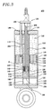
- An inventive double-tube shock absorber 100 for using in a vehicle, e.g., automobile, comprises a cylinder assembly 110 and a piston assembly 130, as shown in Fig. 3.
- the cylinder assembly 110 is provided with an outer cylinder 112 including an outer and an inner surface 121, 122, and an inner cylinder 114 having an outer and an inner surface 123, 124.
- the outer cylinder 112 incorporates therein a first working chamber 116.
- the inner cylinder 114 is located inside the first working chamber 116 and incorporates therein a second working chamber 118.
- the first and the second working chamber 116, 118 are filled with a hydraulic fluid 126 having a constant low viscosity and a magnetorheological (MR) fluid 128 having a changeable viscosity, respectively.
- the first and the second working chamber 116, 118 are isolated from each other for preventing the hydraulic fluid 126 and the MR fluid 128 from interflowing there between.
- the piston assembly 130 is provided with a first piston 132, a second piston 142, three of first piston rods 152, a second piston rod 154 and a rod fixture 156, as shown in Fig 4.
- the first piston 132 having an outer and an inner periphery 133, 134 is movably inserted into the first working chamber 116 with horizontally adjoining its outer periphery 133 to the inner surface 122 of the outer cylinder 112 and its inner periphery 134 to the outer surface 123 of the inner cylinder 114.
- the first piston 132 includes three of first orifices 135 for providing vertical flowing paths for the hydraulic fluid 126 in the first working chamber 116.
- the first piston 132 further includes a first and a second sealing member 136, 137 made of, e.g., Teflon or the like, wherein the first and the second sealing member 136, 137 are secured on the outer periphery 133 and on the inner periphery 134 of the first piston 132, respectively, for preventing the hydraulic fluid 126 from flowing along with the outer and the inner periphery 133, 134 of the first piston 132, respectively.
- a first and a second sealing member 136, 137 made of, e.g., Teflon or the like, wherein the first and the second sealing member 136, 137 are secured on the outer periphery 133 and on the inner periphery 134 of the first piston 132, respectively, for preventing the hydraulic fluid 126 from flowing along with the outer and the inner periphery 133, 134 of the first piston 132, respectively.
- the second piston 142 having an outer periphery 143 is movably inserted into the second working chamber 118 with horizontally adjoining its outer periphery 143 to the inner surface 124 of the inner cylinder 114.
- the second piston 142 includes three of second orifices 144 for providing vertical flowing paths for the MR fluid 128 in the second working chamber 118.
- the second piston 142 further includes a third sealing member 145 made of, e.g., Teflon or the like, and secured on the outer periphery 143 for preventing the MR fluid 128 from flowing along with the outer periphery 143 of the second piston 142.
- first and second orifices 135, 144 can be formed in the first piston 132 and the second piston 142, respectively.
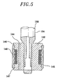
- the second piston 142 is structured for forming a magnetic field generator, e.g., solenoid, in such a way that the second piston 142 is shaped as a spool having an upper and a lower flange 146, 147, and is made of a magnetic permeable material, e.g., ferrite, low-carbon steel or the like, and further is convolved with a coil 148 at the outer periphery 143 thereof between the upper and the lower flange 146, 147. Accordingly, when an electrical current is applied to the coil 148, a magnetic field is generated around the second piston 142, which will, in turn, change the viscosity of the MR fluid 128 passing through the second orifices 144.
- a magnetic field generator e.g., solenoid
- first piston rods 152 for leading the first piston 132 in a reciprocating motion are rigidly joined to the first piston 132 at one end thereof. While the number of the first piston rods 152 is preferably three in the above description, the present invention is not limited thereto. Considering various mechanical factors, e.g., balance, tensile force, compressive force or the like, charged to the first piston rods 152, one or more first piston rods 152 can be rigidly joined to the first piston 132.
- the second piston rod 154 for leading the second piston 142 in a reciprocating motion is rigidly joined to the second piston 142 at one end thereof.
- the second piston rod 154 includes an interior cavity 158 where electrical connections (not shown) for applying the electric signal to the coil 148 are installed.
- first piston rods 152 and the second piston rod 154 are secured to the rod fixture 156 in such a way that the reciprocating motions of the first piston 132 and the second piston 142 are dependent on and coincident to each other during the operation of the double-tube shock absorber 100.
- the double-tube shock absorber 100 further comprises a number of first and second sealing parts 160, 161, a first and a second floating piston 163, 164 and a first and a second accumulator 165, 166.
- the first and second sealing parts 160, 161, respectively, prevent the hydraulic fluid 126 and the MR fluid 128 from leaking along with the first piston rods 152 and the second piston rod 154, respectively.
- the first and the second floating piston 163, 164 are movably inserted into the outer cylinder 112 and the inner cylinder 114, respectively.
- Each of the accumulator 165, 166 is filled with a gas, e.g., nitrogen, wherein the first and the second accumulator 165, 166 are, respectively, necessary to accommodate the hydraulic and the MR fluid 126, 128 displaced by the first piston rods 152 and the second piston rod 154 as well as to allow for thermal expansion of the hydraulic and the MR fluid 126, 128.
- a gas e.g., nitrogen
- the double-tube shock absorber 100 of the present invention utilizes both the hydraulic fluid 126 in the first chamber 116 and the MR fluid 128 in the second chamber 118. Accordingly, the double-tube shock absorber 100 can sensitively respond to the impulse applied thereto by using the hydraulic fluid 126 having relatively low viscosity and, at the same time, can modulate the damping force by using the MR fluid 128 having adjustable viscosity in consideration with various factors, e.g., driving conditions, driver's controls and so on. Furthermore, the expensive MR fluid 128 is employed in only the second working chamber 118 of the inner cylinder 114, thereby reducing the amount of the MR fluid 128 needed and, hence, reducing the manufacturing cost of the double-tube shock absorber 100.
Landscapes
- Engineering & Computer Science (AREA)
- General Engineering & Computer Science (AREA)
- Mechanical Engineering (AREA)
- Physics & Mathematics (AREA)
- Electromagnetism (AREA)
- Fluid-Damping Devices (AREA)
Abstract
Description
- The present invention relates to a shock absorber for use in a motor vehicle; and, more particularly, to a double-tube shock absorber using a magnetorheological (MR) fluid and a hydraulic fluid.
- Typically, motor vehicles are equipped with a suspension system to improve road-adherence and to provide ride-comfort for occupants. The suspension system includes springs and shock absorbers. The shock absorbers are disposed in parallel with the springs to damp the vibration of the springs.
- The shock absorbers utilize a fluid flow system incorporating therein either a hydraulic fluid having a constant viscosity or a fluid having a changeable viscosity, e.g., magnetorheological (MR) fluid. The use of MR fluid is advantageous in that the viscosity thereof can be controlled with the application of a magnetic field in order to adjust a damping force being exerted on the springs depending on a traveling condition.
- Particularly, MR fluid is a free-flowing liquid with a viscosity. Exposure to a magnetic field can transform the liquid into a near-solid in milliseconds; and with the removal of the magnetic field, the fluid can be returned to its liquid state just as quickly. The degree of change in the viscosity of the MR fluid is proportional to the magnitude of the applied magnetic field.
- Figs. 1 and 2 are a cross sectional view illustrating a conventional shock absorber using an MR fluid and an enlarged cross sectional view depicting a piston assembly shown in Fig. 1, respectively, disclosed in USPN 5,284,330 entitled "MAGNETORHEOLOGICAL FLUID DEVICE" issued on January 11, 1994.
- The shock absorber 10 comprises two principal components: a
housing 20 and apiston assembly 30. Thehousing 20 includes a volume of magnetorheological (MR) fluid. The fluid includes carbonyl iron particles suspended in silicone oil. - The
housing 20 is generally of a cylindrical tube with a first closedend 22. Acylindrical sleeve 25 may be affixed to an inner cylinder by any conventional means, e.g., press fit, welding or adhesive to increase the cross-sectional surface area of thehousing 20. The cylinder is closed at a second end thereof by anend member 26. Afirst seal 27 extends about an outer periphery of theend member 26 to prevent fluid leakage between thehousing 20 and theend member 26. - A second
annular seal 28 is housed in a groove in an inner periphery of theend member 26 and seals against apiston rod 32. Ascraper 29 can be used to wipe the MR fluid off the surface ofpiston rod 32 so as to minimize the loss of MR fluid past the secondannular seal 28. - The
housing 20 is provided with afloating piston 21 to separate the MR fluid from a pressurizedaccumulator 23. The pressurizedaccumulator 23 is necessary to accommodate a fluid displaced by thepiston rod 32 as well as to allow for thermal expansion of the fluid. - The
piston assembly 30 is shown in greater detail in Fig. 2. Apiston head 34 is spool shaped with an upper outwardly extendingflange 36 and a lower outwardly extendingflange 38. Acoil 40 is wound upon the spool-shaped piston head 34 between theupper flange 36 and thelower flange 38. Thepiston head 34 is made of a magnetically permeable material, such as low carbon steel.Guide rails 42 are attached around an outside of thepiston head 34 at particular intervals. As shown in Figs. 1 and 2, fourguide rails 42 are shown spaced uniformly about a periphery of thepiston head 34. - An electrical connection is made to the
coil 40 through thepiston rod 32 bylead wires first lead wire 45 is connected to a first end of an electricallyconductive rod 48 which extends through thepiston rod 32 to a Phono-jack connector 46. A center connection of the Phono-jack 46 is connected to afirst end 39 of thecoil 40. Asecond end 41 of windings of thecoil 40 is attached to a "ground" connection on an outside of the Phono-jack 46. An electrical return path, then, includes thepiston rod 32 and theground lead 47. - However, such an MR shock absorber has some inherent drawbacks. First, since the MR fluid has a higher viscosity than the conventional hydraulic fluid even in the absence of a magnetic field, the MR shock absorber tends to exert a harder damping force against external forces applied thereto, resulting in a deteriorated ride-comfort under certain circumstances. Furthermore, the MR fluid is costly, increasing the manufacturing cost of the shock absorber.
- It is, therefore, an object of the present invention to provide a double-tube shock absorber using a magnetorheological fluid and a hydraulic fluid.
- In accordance with the present invention, there is provided a double-tube shock absorber comprising: an outer cylinder having a first working chamber; an inner cylinder located inside the first working chamber and having a second working chamber, wherein the first and the second working chamber are filled with a hydraulic fluid and a magnetorheological fluid, respectively; a first piston movably inserted into the first working chamber; a second piston having a coil movably inserted into the second working chamber, wherein each of the pistons includes one or more orifices; one or more first piston rods for leading the first piston in a reciprocating motion; and a second piston rod for leading the second piston in a reciprocating motion.
- The above and other objects and features of the present invention will become apparent from the following description of preferred embodiments given in conjunction with the accompanying drawings, in which:
- Fig. 1
- is a schematic cross sectional view illustrating a shock absorber using a magnetorheological fluid previously disclosed;
- Fig. 2
- shows an enlarged cross sectional view illustrating a piston assembly incorporated in the shock absorber shown in Fig. 1;
- Fig. 3
- offers a schematic cross sectional view depicting a double-tube shock absorber using both a magnetorheological fluid and a hydraulic fluid in accordance with the present invention;
- Fig. 4
- represents a perspective view portraying piston assembly incorporated in the double-tube shock absorber shown in Fig. 3; and
- Fig. 5
- provides an enlarged cross sectional view of a portion "A" shown in Fig. 3.
- An inventive double-tube shock absorber 100 for using in a vehicle, e.g., automobile, comprises a
cylinder assembly 110 and apiston assembly 130, as shown in Fig. 3. - The
cylinder assembly 110 is provided with anouter cylinder 112 including an outer and aninner surface inner cylinder 114 having an outer and aninner surface outer cylinder 112 incorporates therein afirst working chamber 116. Theinner cylinder 114 is located inside thefirst working chamber 116 and incorporates therein asecond working chamber 118. The first and thesecond working chamber hydraulic fluid 126 having a constant low viscosity and a magnetorheological (MR)fluid 128 having a changeable viscosity, respectively. The first and thesecond working chamber hydraulic fluid 126 and theMR fluid 128 from interflowing there between. - As shown in Figs. 3 and 4, the
piston assembly 130 is provided with afirst piston 132, asecond piston 142, three offirst piston rods 152, asecond piston rod 154 and arod fixture 156, as shown in Fig 4. - The
first piston 132 having an outer and aninner periphery first working chamber 116 with horizontally adjoining itsouter periphery 133 to theinner surface 122 of theouter cylinder 112 and itsinner periphery 134 to theouter surface 123 of theinner cylinder 114. Thefirst piston 132 includes three offirst orifices 135 for providing vertical flowing paths for thehydraulic fluid 126 in the first workingchamber 116. Thefirst piston 132 further includes a first and asecond sealing member second sealing member outer periphery 133 and on theinner periphery 134 of thefirst piston 132, respectively, for preventing thehydraulic fluid 126 from flowing along with the outer and theinner periphery first piston 132, respectively. - The
second piston 142 having anouter periphery 143 is movably inserted into thesecond working chamber 118 with horizontally adjoining itsouter periphery 143 to theinner surface 124 of theinner cylinder 114. Thesecond piston 142 includes three ofsecond orifices 144 for providing vertical flowing paths for theMR fluid 128 in thesecond working chamber 118. Thesecond piston 142 further includes athird sealing member 145 made of, e.g., Teflon or the like, and secured on theouter periphery 143 for preventing theMR fluid 128 from flowing along with theouter periphery 143 of thesecond piston 142. - Although the number of the
orifices 135 and that of theorifices 144 are preferably three, respectively, in the above description, the present invention is not limited thereto. Depending on the maximum amount of damping force required to the double-tube shock absorber 100 of the present invention, one or more first andsecond orifices first piston 132 and thesecond piston 142, respectively. - As shown in Fig. 5, the
second piston 142 is structured for forming a magnetic field generator, e.g., solenoid, in such a way that thesecond piston 142 is shaped as a spool having an upper and alower flange coil 148 at theouter periphery 143 thereof between the upper and thelower flange coil 148, a magnetic field is generated around thesecond piston 142, which will, in turn, change the viscosity of theMR fluid 128 passing through thesecond orifices 144. - Returning to Figs. 3 and 4, three of the
first piston rods 152 for leading thefirst piston 132 in a reciprocating motion are rigidly joined to thefirst piston 132 at one end thereof. While the number of thefirst piston rods 152 is preferably three in the above description, the present invention is not limited thereto. Considering various mechanical factors, e.g., balance, tensile force, compressive force or the like, charged to thefirst piston rods 152, one or morefirst piston rods 152 can be rigidly joined to thefirst piston 132. - The
second piston rod 154 for leading thesecond piston 142 in a reciprocating motion is rigidly joined to thesecond piston 142 at one end thereof. Thesecond piston rod 154 includes aninterior cavity 158 where electrical connections (not shown) for applying the electric signal to thecoil 148 are installed. - Another opposite ends of the
first piston rods 152 and thesecond piston rod 154 are secured to therod fixture 156 in such a way that the reciprocating motions of thefirst piston 132 and thesecond piston 142 are dependent on and coincident to each other during the operation of the double-tube shock absorber 100. - The double-
tube shock absorber 100 further comprises a number of first and second sealingparts piston second accumulator parts hydraulic fluid 126 and the MR fluid 128 from leaking along with thefirst piston rods 152 and thesecond piston rod 154, respectively. The first and the second floatingpiston outer cylinder 112 and theinner cylinder 114, respectively. Each of theaccumulator second accumulator MR fluid first piston rods 152 and thesecond piston rod 154 as well as to allow for thermal expansion of the hydraulic and theMR fluid - As may be seen from the above, it should be appreciated that the double-
tube shock absorber 100 of the present invention utilizes both thehydraulic fluid 126 in thefirst chamber 116 and theMR fluid 128 in thesecond chamber 118. Accordingly, the double-tube shock absorber 100 can sensitively respond to the impulse applied thereto by using thehydraulic fluid 126 having relatively low viscosity and, at the same time, can modulate the damping force by using theMR fluid 128 having adjustable viscosity in consideration with various factors, e.g., driving conditions, driver's controls and so on. Furthermore, the expensive MR fluid 128 is employed in only the second workingchamber 118 of theinner cylinder 114, thereby reducing the amount of theMR fluid 128 needed and, hence, reducing the manufacturing cost of the double-tube shock absorber 100. - While the present invention has been shown and described with respect to the particular embodiments, it will be apparent to those skilled in the art that many changes and modifications may be made without departing from the scope of the invention defined in the appended claims.
Claims (12)
- A double-tube shock absorber comprising:an outer cylinder having a first working chamber; an inner cylinder located inside the first working chamber and having a second working chamber, wherein the first and the second working chamber are filled with a hydraulic fluid and a magnetorheological (MR) fluid, respectively;a first piston movably inserted into the first working chamber;a second piston convolved by a coil and movably inserted into the second working chamber, wherein the first and the second piston include one or more orifices, respectively;one or more first piston rods for leading the first piston in a reciprocating motion; and
a second piston rod for leading the second piston in a reciprocating motion. - The shock absorber of claim 1, wherein the first and the second working chamber are isolated from each other for preventing the hydraulic fluid and the MR fluid from interflowing therebetween.
- The shock absorber of claim 1, wherein the first piston is provided with an outer and an inner periphery and includes a first and a second sealing member, the first and the second sealing member being secured on the outer periphery and on the inner periphery, respectively, for preventing the hydraulic fluid from flowing along with the outer and the inner periphery of the first piston.
- The shock absorber of claim 1, wherein the second piston is provided with an outer periphery and includes a third sealing member secured on the outer periphery for preventing the MR fluid from flowing along with the outer periphery of the second piston.
- The shock absorber of claim 1, wherein the second piston is structured to form a magnetic field generator, wherein the second piston is made of a magnetic material and is convolved with the coil at an outer periphery thereof.
- The shock absorber of claim 1 further comprising a rod fixture rigidly holding thereon the first and the second piston rod at once in such a way that the reciprocating motions of the first and the second piston are dependent on and coincident to each other.
- The shock absorber of claim 1 further comprising a number of sealing parts for preventing the hydraulic fluid and the MR fluid from leaking along with the first piston rod and the second piston rod.
- The shock absorber of claim 1, wherein the second piston rod includes an interior cavity through which an electrical current is applied to the coil.
- The shock absorber of claim 1 further comprising a first and a second floating piston movably inserted into the outer and the inner cylinder, respectively.
- The shock absorber of claim 9 further comprising a first and a second accumulator filled with a gas, wherein the first and the second accumulator are installed in the outer and inner cylinder, respectively.
- A motor vehicle incorporating therein the double-tube shock absorber according to claim 1.
- A suspension system incorporating therein the double-tube shock absorber according to claim 1.
Priority Applications (2)
| Application Number | Priority Date | Filing Date | Title |
|---|---|---|---|
| DE2000618956 DE60018956T2 (en) | 2000-12-29 | 2000-12-29 | Twin-tube vibration damper filled with hydraulic fluid and magnetorheological fluid |
| EP20000128693 EP1219857B1 (en) | 2000-12-29 | 2000-12-29 | Double-tube shock absorber using a hydraulic fluid and a magnetorheological fluid |
Applications Claiming Priority (1)
| Application Number | Priority Date | Filing Date | Title |
|---|---|---|---|
| EP20000128693 EP1219857B1 (en) | 2000-12-29 | 2000-12-29 | Double-tube shock absorber using a hydraulic fluid and a magnetorheological fluid |
Publications (2)
| Publication Number | Publication Date |
|---|---|
| EP1219857A1 true EP1219857A1 (en) | 2002-07-03 |
| EP1219857B1 EP1219857B1 (en) | 2005-03-23 |
Family
ID=8170861
Family Applications (1)
| Application Number | Title | Priority Date | Filing Date |
|---|---|---|---|
| EP20000128693 Expired - Lifetime EP1219857B1 (en) | 2000-12-29 | 2000-12-29 | Double-tube shock absorber using a hydraulic fluid and a magnetorheological fluid |
Country Status (2)
| Country | Link |
|---|---|
| EP (1) | EP1219857B1 (en) |
| DE (1) | DE60018956T2 (en) |
Cited By (10)
| Publication number | Priority date | Publication date | Assignee | Title |
|---|---|---|---|---|
| EP1408253A3 (en) * | 2002-10-08 | 2004-06-16 | Delphi Technologies, Inc. | Magnetorheological piston having a core |
| KR100514370B1 (en) * | 2002-10-21 | 2005-09-13 | 현대자동차주식회사 | Apparatus for controlling a rolling for power train in vehicles |
| EP1903252A1 (en) * | 2006-09-19 | 2008-03-26 | Delphi Technologies, Inc. | Magnetorheological damper |
| US7897060B2 (en) | 2004-08-27 | 2011-03-01 | Fraunhofer-Gesselschaft Zur Forderung Der Angewandten Forschung E.V. | Magnetorheological materials having a high switching factor and use thereof |
| ES2373195A1 (en) * | 2008-12-01 | 2012-02-01 | Francisco Javier Muñoz Labrador | Pro-active magnetoreological suspension system (Machine-translation by Google Translate, not legally binding) |
| KR101556716B1 (en) | 2014-02-19 | 2015-10-02 | 고두일 | Shock absorber apparatus for vehicle provided with restitutive strusture by magnetic force |
| CN110953284A (en) * | 2019-12-05 | 2020-04-03 | 广西科技大学 | A series extruded magnetorheological damper |
| CN113508690A (en) * | 2021-05-08 | 2021-10-19 | 河南科技大学 | A flexible threshing device that can automatically adjust the threshing gap |
| CN117662663A (en) * | 2023-12-01 | 2024-03-08 | 贵州轮胎股份有限公司 | ring buffer |
| CN119393477A (en) * | 2024-12-30 | 2025-02-07 | 杭州安衡迅科技有限公司 | Integrated vibration damper |
Families Citing this family (3)
| Publication number | Priority date | Publication date | Assignee | Title |
|---|---|---|---|---|
| DE102007017589B3 (en) * | 2007-04-13 | 2008-10-02 | Fraunhofer-Gesellschaft zur Förderung der angewandten Forschung e.V. | Damping device with field-controllable fluid |
| CN102561173B (en) * | 2011-12-19 | 2014-07-16 | 北京工业大学 | Speed type structure connecting and locking device containing shear thickening liquid |
| CN109058355B (en) * | 2018-07-24 | 2020-06-19 | 南京理工大学 | Hydraulic cylinder suitable for instantaneous high-speed heavy load buffering |
Citations (6)
| Publication number | Priority date | Publication date | Assignee | Title |
|---|---|---|---|---|
| DE4200977A1 (en) * | 1992-01-16 | 1993-07-22 | Montan Hydraulik Gmbh & Co Kg | SHOCK ABSORBER |
| GB2267947A (en) * | 1992-06-17 | 1993-12-22 | Gec Alsthom Ltd | Controllable motion-damper |
| US5284330A (en) | 1992-06-18 | 1994-02-08 | Lord Corporation | Magnetorheological fluid devices |
| EP0607545A1 (en) * | 1992-12-02 | 1994-07-27 | Öhlins Racing Ab | Shock absorber |
| WO1999027273A2 (en) * | 1997-11-25 | 1999-06-03 | Lord Corporation | Adjustable valve and vibration dampers utilizing same |
| US5956951A (en) * | 1996-09-20 | 1999-09-28 | Mr Technologies | Adjustable magneto-rheological fluid device |
-
2000
- 2000-12-29 DE DE2000618956 patent/DE60018956T2/en not_active Expired - Lifetime
- 2000-12-29 EP EP20000128693 patent/EP1219857B1/en not_active Expired - Lifetime
Patent Citations (6)
| Publication number | Priority date | Publication date | Assignee | Title |
|---|---|---|---|---|
| DE4200977A1 (en) * | 1992-01-16 | 1993-07-22 | Montan Hydraulik Gmbh & Co Kg | SHOCK ABSORBER |
| GB2267947A (en) * | 1992-06-17 | 1993-12-22 | Gec Alsthom Ltd | Controllable motion-damper |
| US5284330A (en) | 1992-06-18 | 1994-02-08 | Lord Corporation | Magnetorheological fluid devices |
| EP0607545A1 (en) * | 1992-12-02 | 1994-07-27 | Öhlins Racing Ab | Shock absorber |
| US5956951A (en) * | 1996-09-20 | 1999-09-28 | Mr Technologies | Adjustable magneto-rheological fluid device |
| WO1999027273A2 (en) * | 1997-11-25 | 1999-06-03 | Lord Corporation | Adjustable valve and vibration dampers utilizing same |
Cited By (11)
| Publication number | Priority date | Publication date | Assignee | Title |
|---|---|---|---|---|
| EP1408253A3 (en) * | 2002-10-08 | 2004-06-16 | Delphi Technologies, Inc. | Magnetorheological piston having a core |
| KR100514370B1 (en) * | 2002-10-21 | 2005-09-13 | 현대자동차주식회사 | Apparatus for controlling a rolling for power train in vehicles |
| US7897060B2 (en) | 2004-08-27 | 2011-03-01 | Fraunhofer-Gesselschaft Zur Forderung Der Angewandten Forschung E.V. | Magnetorheological materials having a high switching factor and use thereof |
| EP1903252A1 (en) * | 2006-09-19 | 2008-03-26 | Delphi Technologies, Inc. | Magnetorheological damper |
| ES2373195A1 (en) * | 2008-12-01 | 2012-02-01 | Francisco Javier Muñoz Labrador | Pro-active magnetoreological suspension system (Machine-translation by Google Translate, not legally binding) |
| KR101556716B1 (en) | 2014-02-19 | 2015-10-02 | 고두일 | Shock absorber apparatus for vehicle provided with restitutive strusture by magnetic force |
| CN110953284A (en) * | 2019-12-05 | 2020-04-03 | 广西科技大学 | A series extruded magnetorheological damper |
| CN113508690A (en) * | 2021-05-08 | 2021-10-19 | 河南科技大学 | A flexible threshing device that can automatically adjust the threshing gap |
| CN117662663A (en) * | 2023-12-01 | 2024-03-08 | 贵州轮胎股份有限公司 | ring buffer |
| CN119393477A (en) * | 2024-12-30 | 2025-02-07 | 杭州安衡迅科技有限公司 | Integrated vibration damper |
| CN119393477B (en) * | 2024-12-30 | 2025-06-10 | 杭州安衡迅科技有限公司 | Integrated vibration damper |
Also Published As
| Publication number | Publication date |
|---|---|
| DE60018956D1 (en) | 2005-04-28 |
| EP1219857B1 (en) | 2005-03-23 |
| DE60018956T2 (en) | 2006-03-23 |
Similar Documents
| Publication | Publication Date | Title |
|---|---|---|
| US6279702B1 (en) | Shock absorber using a hydraulic fluid and a magnetorheological fluid | |
| US6360856B1 (en) | Double-tube shock absorber using a hydraulic fluid and a magnetorheological fluid | |
| US12005755B2 (en) | Methods and apparatus for controlling a fluid damper | |
| EP1219857B1 (en) | Double-tube shock absorber using a hydraulic fluid and a magnetorheological fluid | |
| US5632361A (en) | Vibration damper, in particular for motor vehicles | |
| US6382369B1 (en) | Magneto-rheological fluid damper with an external coil | |
| KR101024124B1 (en) | Pressurized Magnetorheological Fluid Damper | |
| US6419058B1 (en) | Magnetorheological damper with piston bypass | |
| JP3055939B2 (en) | Vehicle engine mount | |
| EP0414508A1 (en) | Vibration damping device | |
| US6390253B1 (en) | Magneto-rheological damping apparatus | |
| US11280380B2 (en) | Magnetorheological hydraulic damper with passive damping chamber | |
| JP2000514161A (en) | Variable vibration device | |
| EP0718523A1 (en) | Vibration damping device using ER fluids | |
| JPH02296024A (en) | Rotary shock absorber | |
| EP1219858B1 (en) | Shock absorber using a hydraulic fluid and a magnetorheological fluid | |
| KR100696952B1 (en) | Asymmetric Damping Control Damper Using Magnetofluidic Fluids | |
| RU2084721C1 (en) | Hydraulic shock-absorber | |
| US5261649A (en) | Elastic mount having main fluid chamber communicating with auxiliary fluid chamber partially defined by oscillating plate actuated by moving coil in annular gap between two yokes connected to permanent magnet | |
| EP1070872A1 (en) | Controlled oscillating damper | |
| JP3418380B2 (en) | shock absorber | |
| JP2002195340A (en) | Double tube type shock absorber | |
| RU2204067C2 (en) | Hydraulic shock absorber | |
| KR101963496B1 (en) | Magneto Rheological For Vehicle | |
| CN210830288U (en) | Magnetorheological vibration damper |
Legal Events
| Date | Code | Title | Description |
|---|---|---|---|
| PUAI | Public reference made under article 153(3) epc to a published international application that has entered the european phase |
Free format text: ORIGINAL CODE: 0009012 |
|
| AK | Designated contracting states |
Kind code of ref document: A1 Designated state(s): AT BE CH CY DE DK ES FI FR GB GR IE IT LI LU MC NL PT SE TR |
|
| AX | Request for extension of the european patent |
Free format text: AL;LT;LV;MK;RO;SI |
|
| 17P | Request for examination filed |
Effective date: 20021218 |
|
| AKX | Designation fees paid |
Designated state(s): DE FR GB IT |
|
| GRAP | Despatch of communication of intention to grant a patent |
Free format text: ORIGINAL CODE: EPIDOSNIGR1 |
|
| GRAS | Grant fee paid |
Free format text: ORIGINAL CODE: EPIDOSNIGR3 |
|
| GRAA | (expected) grant |
Free format text: ORIGINAL CODE: 0009210 |
|
| AK | Designated contracting states |
Kind code of ref document: B1 Designated state(s): DE FR GB IT |
|
| REG | Reference to a national code |
Ref country code: GB Ref legal event code: FG4D |
|
| REG | Reference to a national code |
Ref country code: IE Ref legal event code: FG4D |
|
| REF | Corresponds to: |
Ref document number: 60018956 Country of ref document: DE Date of ref document: 20050428 Kind code of ref document: P |
|
| PLBE | No opposition filed within time limit |
Free format text: ORIGINAL CODE: 0009261 |
|
| STAA | Information on the status of an ep patent application or granted ep patent |
Free format text: STATUS: NO OPPOSITION FILED WITHIN TIME LIMIT |
|
| ET | Fr: translation filed | ||
| 26N | No opposition filed |
Effective date: 20051227 |
|
| REG | Reference to a national code |
Ref country code: FR Ref legal event code: PLFP Year of fee payment: 17 |
|
| REG | Reference to a national code |
Ref country code: FR Ref legal event code: PLFP Year of fee payment: 18 |
|
| REG | Reference to a national code |
Ref country code: FR Ref legal event code: PLFP Year of fee payment: 19 |
|
| PGFP | Annual fee paid to national office [announced via postgrant information from national office to epo] |
Ref country code: FR Payment date: 20190821 Year of fee payment: 20 |
|
| PGFP | Annual fee paid to national office [announced via postgrant information from national office to epo] |
Ref country code: DE Payment date: 20190820 Year of fee payment: 20 |
|
| PGFP | Annual fee paid to national office [announced via postgrant information from national office to epo] |
Ref country code: IT Payment date: 20191216 Year of fee payment: 20 |
|
| PGFP | Annual fee paid to national office [announced via postgrant information from national office to epo] |
Ref country code: GB Payment date: 20191008 Year of fee payment: 20 |
|
| REG | Reference to a national code |
Ref country code: DE Ref legal event code: R071 Ref document number: 60018956 Country of ref document: DE |
|
| REG | Reference to a national code |
Ref country code: GB Ref legal event code: PE20 Expiry date: 20201228 |
|
| PG25 | Lapsed in a contracting state [announced via postgrant information from national office to epo] |
Ref country code: GB Free format text: LAPSE BECAUSE OF EXPIRATION OF PROTECTION Effective date: 20201228 |