EP1219797A1 - Système d'admission de gaz dans une chambre à combustion comportant des moyens de déflection - Google Patents
Système d'admission de gaz dans une chambre à combustion comportant des moyens de déflection Download PDFInfo
- Publication number
- EP1219797A1 EP1219797A1 EP01403249A EP01403249A EP1219797A1 EP 1219797 A1 EP1219797 A1 EP 1219797A1 EP 01403249 A EP01403249 A EP 01403249A EP 01403249 A EP01403249 A EP 01403249A EP 1219797 A1 EP1219797 A1 EP 1219797A1
- Authority
- EP
- European Patent Office
- Prior art keywords
- cylinder
- duct
- intake system
- wall
- intake
- Prior art date
- Legal status (The legal status is an assumption and is not a legal conclusion. Google has not performed a legal analysis and makes no representation as to the accuracy of the status listed.)
- Ceased
Links
Images


Classifications
-
- F—MECHANICAL ENGINEERING; LIGHTING; HEATING; WEAPONS; BLASTING
- F02—COMBUSTION ENGINES; HOT-GAS OR COMBUSTION-PRODUCT ENGINE PLANTS
- F02B—INTERNAL-COMBUSTION PISTON ENGINES; COMBUSTION ENGINES IN GENERAL
- F02B31/00—Modifying induction systems for imparting a rotation to the charge in the cylinder
- F02B31/04—Modifying induction systems for imparting a rotation to the charge in the cylinder by means within the induction channel, e.g. deflectors
-
- F—MECHANICAL ENGINEERING; LIGHTING; HEATING; WEAPONS; BLASTING
- F02—COMBUSTION ENGINES; HOT-GAS OR COMBUSTION-PRODUCT ENGINE PLANTS
- F02B—INTERNAL-COMBUSTION PISTON ENGINES; COMBUSTION ENGINES IN GENERAL
- F02B1/00—Engines characterised by fuel-air mixture compression
- F02B1/02—Engines characterised by fuel-air mixture compression with positive ignition
- F02B1/04—Engines characterised by fuel-air mixture compression with positive ignition with fuel-air mixture admission into cylinder
-
- F—MECHANICAL ENGINEERING; LIGHTING; HEATING; WEAPONS; BLASTING
- F02—COMBUSTION ENGINES; HOT-GAS OR COMBUSTION-PRODUCT ENGINE PLANTS
- F02B—INTERNAL-COMBUSTION PISTON ENGINES; COMBUSTION ENGINES IN GENERAL
- F02B75/00—Other engines
- F02B75/12—Other methods of operation
- F02B2075/125—Direct injection in the combustion chamber for spark ignition engines, i.e. not in pre-combustion chamber
-
- F—MECHANICAL ENGINEERING; LIGHTING; HEATING; WEAPONS; BLASTING
- F02—COMBUSTION ENGINES; HOT-GAS OR COMBUSTION-PRODUCT ENGINE PLANTS
- F02F—CYLINDERS, PISTONS OR CASINGS, FOR COMBUSTION ENGINES; ARRANGEMENTS OF SEALINGS IN COMBUSTION ENGINES
- F02F1/00—Cylinders; Cylinder heads
- F02F1/24—Cylinder heads
- F02F1/42—Shape or arrangement of intake or exhaust channels in cylinder heads
- F02F1/4214—Shape or arrangement of intake or exhaust channels in cylinder heads specially adapted for four or more valves per cylinder
-
- F—MECHANICAL ENGINEERING; LIGHTING; HEATING; WEAPONS; BLASTING
- F02—COMBUSTION ENGINES; HOT-GAS OR COMBUSTION-PRODUCT ENGINE PLANTS
- F02F—CYLINDERS, PISTONS OR CASINGS, FOR COMBUSTION ENGINES; ARRANGEMENTS OF SEALINGS IN COMBUSTION ENGINES
- F02F1/00—Cylinders; Cylinder heads
- F02F1/24—Cylinder heads
- F02F2001/244—Arrangement of valve stems in cylinder heads
- F02F2001/245—Arrangement of valve stems in cylinder heads the valve stems being orientated at an angle with the cylinder axis
-
- F—MECHANICAL ENGINEERING; LIGHTING; HEATING; WEAPONS; BLASTING
- F02—COMBUSTION ENGINES; HOT-GAS OR COMBUSTION-PRODUCT ENGINE PLANTS
- F02F—CYLINDERS, PISTONS OR CASINGS, FOR COMBUSTION ENGINES; ARRANGEMENTS OF SEALINGS IN COMBUSTION ENGINES
- F02F3/00—Pistons
- F02F3/26—Pistons having combustion chamber in piston head
-
- Y—GENERAL TAGGING OF NEW TECHNOLOGICAL DEVELOPMENTS; GENERAL TAGGING OF CROSS-SECTIONAL TECHNOLOGIES SPANNING OVER SEVERAL SECTIONS OF THE IPC; TECHNICAL SUBJECTS COVERED BY FORMER USPC CROSS-REFERENCE ART COLLECTIONS [XRACs] AND DIGESTS
- Y02—TECHNOLOGIES OR APPLICATIONS FOR MITIGATION OR ADAPTATION AGAINST CLIMATE CHANGE
- Y02T—CLIMATE CHANGE MITIGATION TECHNOLOGIES RELATED TO TRANSPORTATION
- Y02T10/00—Road transport of goods or passengers
- Y02T10/10—Internal combustion engine [ICE] based vehicles
- Y02T10/12—Improving ICE efficiencies
Definitions
- the invention relates to a gas intake system in at least one combustion chamber of a cylinder of a combustion.
- Petrol engines especially injection engines direct, optimize engine operation with so-called “poor” mixtures, that is to say fuel mixtures in which there is a strong excess of oxidizing gas, such as air, relative to the amount of fuel introduced into the cylinder.
- the excess gas prevents part of the fuel remains unburnt after combustion and is discharged with exhaust gases.
- the ignition is done by auto-ignition fuel in areas where the gas / fuel mixture is rich.
- Optimizing combustion in diesel engines involves in particular promoting the air / fuel mixture and thus bringing air around the fuel jets.
- the vortex movement is notably created at the end of compression, and particularly during the injection phase of the fuel, by the flow of air in the combustion carried out in the piston head.
- the "swirl" movement created during the phase fuel intake also requires a specific layout of the admission system.
- permeability being defined as the flow air flow through the inlet port of a valve when its opening. Reduced permeability leads to degradation filling the engine combustion chambers with air, especially at high loads. Indeed, in this case, the quantity air admitted into the cylinder is less than the amount of air which is necessary for optimal combustion of the mixture air / fuel.
- the devices increase the number of parts to to assemble, the complexity of the admission systems as well as their cost of assembly.
- the invention provides a system for admitting air into at least one combustion chamber of a cylinder of a combustion engine, which comprises at least one duct for admission of gases, in particular of air, which opens into the chamber through an inlet orifice which is closed by an intake valve which has a control stem and which is eccentric relative to the axis of the cylinder and of the type at least one downstream section of the intake duct includes aerodynamic deflection means, characterized in that the aerodynamic deflection means comprise at least a first protrusion of the internal surface of the wall which is located on a first deflection zone of the internal surface of the wall of the duct in the vicinity of the valve stem, so to favor the formation of a so-called "swirl" vortex movement in which the gases contained in the cylinder are driven in a rotational movement around an axis substantially parallel to the axis of the cylinder.
- an upstream, downstream orientation will be used corresponding to the general direction of gas flow in the intake system, from left to right according to figure 1.
- the description deals with an injection petrol engine direct, however it is not limiting.
- the invention can apply to different types of engines such as a indirect injection petrol or diesel engine.
- the cylinder 10 is produced in the form of a bore 12 cylindrical with vertical axis A1 arranged in an engine block 14.
- a piston 16 has an axial reciprocating movement in the bore 12 and it delimits, downwards, the volume of the cylinder.
- the engine block 14 is covered with a cylinder head 18, one side of which lower 20 delimits cylinder 10 upwards.
- combustion chamber 22 The space between the piston 16, the cylinder head 18 and the cylinder 10 is called combustion chamber 22.
- the engine cylinder head has an intake duct 24 gases, especially air, in cylinder 10.
- the intake duct 24, here comprises an upstream section 26 which is divided into first and second downstream sections 28 and 30.
- Each first and second downstream sections 28 and 30 opens into combustion chamber 22 through a first and a second inlet ports 32 and 34 closed by a first and a second intake valves 36 and 38 respectively.
- Each of the intake valves 36 and 38 is controlled by a tail 37 and 39 respectively which extends in the downstream section 28 and 30 and crosses the wall of the conduit 24.
- the first and second orifices 32, 34 are offset by relative to the axis A1 of cylinder 10.
- the cylinder 10 also includes a spark plug 35 to sparks, which can be arranged substantially along the axis A1 of the cylinder.
- the cylinder head 18 also includes a conduit exhaust 42 of the burnt gas which opens through an orifice outlet 44 in the underside 20 of the cylinder head.
- Each of the outlet orifices 44 of the exhaust duct 42 is intended for be closed by an exhaust valve 46 which has, by example, a diameter greater than the diameter of the valves 36 and 38.
- the cylinder 10 also includes a fuel injector, the nose 48 of which opens directly in room 22.
- the piston 16 has, in its upper face 50, a concave recess 52 (also called bowl) which, when viewed from above, has a shape substantially circular.
- the recess 52 is eccentric with respect to the axis A1 of the cylinder. Indeed, it is interesting that the injector and the recess 52 are arranged so that the injection axis of fuel through the injector comes in roughly tangential to the lateral surface of the recess 52, inwards of it.
- Turbulence forms in particular in sections downstream 28 and 30 near the inlet ports 32 and 34.
- the turbulence is also due to the detachment of the air boundary layer of the inner surface of the walls of downstream sections 28 and 30.
- the existence of the boundary layer is due to the friction of the air with the internal surface of the walls.
- it is formed by air which are located near the surface internal and whose flow velocity is different from the velocity overall air in the corresponding downstream section 28, 30.
- His thickness is the distance at which the air speed reaches 99% of the speed of the flow undisturbed by friction with the internal surface 64.
- Figure 2 shows in particular the flow of a flow of air in the downstream section 28 of an intake system according to the state of technique.
- the air flow comprises a central flow 60 and a layer boundary 62 which is located between the central flow 60 and a surface internal 64 of the downstream section 28.
- the flow of the boundary layer 62 is laminar upstream of the downstream section 28, that is to say that the boundary layer 62 is bonded to the internal surface 64 of the wall of the downstream section 28.
- the flow of the boundary layer 62 becomes turbulent in a downstream end zone 66, that is to say that the boundary layer 62 is detached from the downstream end zone 66 of the internal surface 64 of the downstream section 28.
- the detachment thus produced is unfavorable to the flow of air in the intake duct 24. It increases with the flow air flowing in the intake duct 24. In addition, it does not not allow to obtain an optimal swirl movement.
- deflection means aerodynamics 68 include at least a first protrusion 70 of the internal surface 64 of the wall of the first downstream section 28.
- the protuberance 70 is located in a first zone of deflection 72 of the internal surface 64 of the wall of the downstream section 28 of the conduit 24, near the valve stem 37.
- Such a protuberance 70 makes it possible to promote the diet laminar air flow at the free downstream end of the duct 24. It thus makes it possible to orient the air flow in an area orifice 32 which promotes the formation of movement swirl swirl.
- the air flow is directed towards an area of the orifice 32 located near the tubular wall of the bore 12 of the cylinder
- the aerodynamic deflection is such that the boundary layer 62 is held against the internal wall 64. The flow flow is then laminar until it enters the combustion chamber 22.
- the first protuberance 70 makes it possible to orient the air flow and change its incident angle to the wall cylindrical of the combustion chamber 22.
- Figures 3 and 4 show in strong lines the downstream section 28 according to the invention which comprises the first protuberance 70, as well as the direction 71 of the air during their entering the combustion chamber 22.
- the dotted lines 74 represent the position of the internal surface 64 of the wall of the downstream section 28 according to the state of the technical, They also represent direction 75 of the air during their entry into the combustion chamber 22.
- the angle that extends between the cylindrical wall of the chamber 22 and the air direction 71 of the invention is smaller than the angle separating said cylindrical wall from the air direction 75 according to the state of the art.
- the distance D1 between the inlet port 32 and the air impact zone with the tubular wall of the combustion 22 according to the invention is lower than the distance D2 corresponding according to the state of the art.
- the shape, dimensions and position of the protuberance 70 are determined so that the permeability of the inlet port 32 corresponding, as well as the swirling swirl movement are optimal.
- the intake duct 24 can be of the tangential type, that is to say that the direction of the air flow passing through the orifices input 32 and 34 is oriented substantially tangential to the cylindrical wall of the combustion chamber 22.
- the first protuberance 70 can be made in one piece with the intake duct 24.
- the first protuberance 70 can be produced during molding the intake duct 24.
- the protuberance 70 can also be obtained by deformation of the internal surface 64 of the wall of the conduit 24 of outside to inside.
- the deformation can for example be carried out by a punch of which a pressure head applies a force on the outer surface of the wall of the conduit 24 facing the deflection zone 72 so as to cause the deformation of the conduit 24.
- the first protuberance 70 can be attached, for example by welding or gluing, on the first deflection zone 72 of the conduit 24.
- the deflection means aerodynamics 68 have a second protuberance 76 of the internal surface 64 of the wall of the downstream section 28 of the conduit 24. It is located on a second deflection zone 78, near valve stem 37.
- the second deflection zone 78 is located substantially at the opposite of the first deflection zone 72 with respect to the stem 37 of valve 36, in accordance with FIG. 7.
- the interaction between valve stem 37 and the second protuberance 76 also makes it possible to press the boundary layer 62 against the internal surface 64 of the wall of the first downstream section 28 so as to favor the laminar flow regime the air in the free downstream end of the conduit 24 and also allows to orient the flow in an area of the orifice 32 which promotes the formation of the swirl swirl movement.
- the flow is preferably oriented in the area before orifice 32, i.e. the area downstream of the duct 24 relative to the general direction of air flow in the intake duct 24.
- the section of the inlet port 32 of the valve 36 is sufficient to allow the passage of the quantity of air necessary for the combustion of the fuel charge.
- the second valve 38 then closes the second inlet port 34 and the admission system according to the invention allows the introduction, into the combustion chamber 22, of the quantity of air required animated by a high swirl movement.
- the presence of the first 70 and second 76 protuberances disadvantage the separation of the boundary layer and directs the flow of air, which increases the formation of the swirl movement by the admission system.
- the large swirl swirl movement allows promote the mixing of air and fuel in the combustion 22 and improve engine performance.
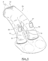
- Figure 5 illustrates in perspective an intake system which includes in particular a first 28 and a second 30 sections downstream, each comprising a first 70 and a second 76 protuberances.
- the intake duct 24 described previously comprises two downstream sections 28 and 30 which each lead into the combustion chamber through an inlet 32 and 34 respectively.
- the air intake system may include a intake duct opening into the combustion chamber by a single inlet orifice closed by a valve.
Landscapes
- Engineering & Computer Science (AREA)
- Chemical & Material Sciences (AREA)
- Combustion & Propulsion (AREA)
- Mechanical Engineering (AREA)
- General Engineering & Computer Science (AREA)
- Cylinder Crankcases Of Internal Combustion Engines (AREA)
Abstract
Description
caractérisé en ce que les moyens de déflexion aérodynamique comportent au moins une première protubérance de la surface interne de la paroi qui est située sur une première zone de déflexion de la surface interne de la paroi du conduit à proximité de la queue de soupape, de façon à favoriser la formation d'un mouvement tourbillonnaire dit de "swirl" dans lequel les gaz contenus dans le cylindre sont animés d'un mouvement de rotation autour d'un axe sensiblement parallèle à l'axe du cylindre.
- les moyens de déflexion comportent une seconde protubérance qui est située dans une seconde zone de déflexion agencée sensiblement en vis-à-vis de la première zone de déflexion ;
- l'une au moins des protubérances est réalisée en une seule pièce avec le conduit ;
- l'une au moins des protubérances est réalisée par déformation de la surface interne de la paroi du conduit, de l'extérieur vers l'intérieur ;
- l'une au moins des protubérances est rapportée sur l'une des zones de déflexion du conduit ;
- l'un au moins des conduits est de type tangentiel à la paroi cylindrique de la chambre de combustion ;
- il comporte deux conduits d'admission, et les deux conduits d'admission comportent chacun au moins une protubérance et sont sensiblement symétriques l'un par rapport à l'autre selon un plan de symétrie médian.
- la figure 1 représente une vue schématique en coupe axiale illustrant un cylindre d'un moteur équipé d'un système d'admission selon l'état de la technique ;
- la figure 2 est une vue en coupe selon un plan sensiblement horizontal 2-2 de la figure 1 du système d'admission selon l'état de la technique ;
- la figure 3 est une vue en coupe similaire à celle représentée à la figure 2 qui illustre un système d'admission selon l'invention ;
- la figure 4 est une vue similaire à celle représentée à la figure précédente, le système d'admission étant réalisé selon une variante ;
- la figure 5 est une vue en perspective du système d'admission réalisé selon la variante représentée à la figure précédente.
Claims (7)
- Système d'admission de gaz dans au moins une chambre de combustion (22) d'un cylindre (10) d'un moteur à combustion, qui comporte au moins un conduit d'admission (24) des gaz, notamment d'air, qui débouche dans la chambre (22) par un orifice d'entrée (32, 34) qui est obturé par une soupape d'admission (36, 38) qui comporte une queue de commande (37, 39) et qui est excentré par rapport à l'axe (A1) du cylindre (10) et du type dont au moins un tronçon aval (28, 30) du conduit d'admission (24) comporte des moyens de déflexion aérodynamique (68),
caractérisé en ce que les moyens de déflexion aérodynamique (68) comportent au moins une première protubérance (70) de la surface interne (64) de la paroi qui est située dans une première zone de déflexion (72) de la surface interne (64) de la paroi du conduit (24) à proximité de la queue de soupape (37, 39), de façon à favoriser la formation d'un mouvement tourbillonnaire dit de "swirl" dans lequel les gaz contenus dans le cylindre (10) sont animés d'un mouvement de rotation autour d'un axe sensiblement parallèle à l'axe du cylindre (10). - Système d'admission selon la revendication précédente, caractérisé en ce que les moyens de déflexion (68) comportent une seconde protubérance (76) qui est située dans une seconde zone de déflexion (78) agencée sensiblement en vis-à-vis de la première zone de déflexion (72).
- Système d'admission selon l'une des revendications précédentes, caractérisé en ce que l'une au moins des protubérances (70, 76) est réaiisée en une seule pièce avec le conduit (24).
- Système d'admission selon la revendication précédente, caractérisé en ce que l'une au moins des protubérances (70, 76) est réalisée par déformation de la surface interne (64) de la paroi du conduit (24), de l'extérieur vers l'intérieur.
- Système d'admission selon l'une quelconque des revendications précédentes, caractérisé en ce que l'une au moins des protubérances (70,76) est rapportée dans l'une des zones de déflexion (72, 78) du conduit (24).
- Système d'admission selon l'une quelconque des revendications précédentes, caractérisé en ce que l'un au moins des conduits (24) est de type tangentiel à la paroi cylindrique de la chambre de combustion (22).
- Système d'admission selon l'une quelconque des revendications précédentes, caractérisé en ce qu'il comporte deux tronçons aval (28, 30), et en ce que les deux tronçons aval (28, 30) comportent chacun au moins une protubérance (70, 76) et sont sensiblement symétriques l'un par rapport à l'autre selon un plan (P) de symétrie médian.
Applications Claiming Priority (2)
| Application Number | Priority Date | Filing Date | Title |
|---|---|---|---|
| FR0017156A FR2819015B1 (fr) | 2000-12-28 | 2000-12-28 | Systeme d'admission de gaz dans une chambre de combustion comportant des moyens de deflexion |
| FR0017156 | 2000-12-28 |
Publications (1)
| Publication Number | Publication Date |
|---|---|
| EP1219797A1 true EP1219797A1 (fr) | 2002-07-03 |
Family
ID=8858298
Family Applications (1)
| Application Number | Title | Priority Date | Filing Date |
|---|---|---|---|
| EP01403249A Ceased EP1219797A1 (fr) | 2000-12-28 | 2001-12-14 | Système d'admission de gaz dans une chambre à combustion comportant des moyens de déflection |
Country Status (2)
| Country | Link |
|---|---|
| EP (1) | EP1219797A1 (fr) |
| FR (1) | FR2819015B1 (fr) |
Cited By (2)
| Publication number | Priority date | Publication date | Assignee | Title |
|---|---|---|---|---|
| EP1550801A1 (fr) * | 2003-12-30 | 2005-07-06 | Iveco S.p.A. | Culasse pour un moteur à combustion interne à gaz et procédé de sa fabrication |
| CN113250868A (zh) * | 2021-06-30 | 2021-08-13 | 潍柴动力股份有限公司 | 一种进气道结构及发动机 |
Citations (8)
| Publication number | Priority date | Publication date | Assignee | Title |
|---|---|---|---|---|
| DE850967C (de) * | 1951-05-06 | 1952-09-29 | Maschf Augsburg Nuernberg Ag | Einrichtung zur Erzeugung einer Drehbewegung der Luftladung im Zylinder einer luftverdichtenden Brennkraftmaschine |
| CH318570A (de) * | 1951-11-27 | 1957-01-15 | Texaco Development Corp | Viertakt-Verbrennungsmotor |
| GB835098A (en) * | 1956-12-12 | 1960-05-18 | Augsburg I Nurnberg A G Maschf | Improvements in and relating to internal combustion engines |
| US3335707A (en) * | 1964-04-25 | 1967-08-15 | Motoren Werke Mannheim Ag | Internal combustion engines |
| US4344394A (en) * | 1978-06-12 | 1982-08-17 | Automotive Engine Associates | High swirl very low pollution piston engine employing optimizable vorticity |
| US4606308A (en) * | 1985-09-16 | 1986-08-19 | General Motors Corporation | Engine cylinder intake port |
| US5762042A (en) * | 1996-02-29 | 1998-06-09 | Mitsubishi Jidosha Kogyo Kabushiki Kaisha | Internal combustion engine |
| US6105545A (en) * | 1999-02-12 | 2000-08-22 | General Motors Corporation | Intake port for an internal combustion engine |
-
2000
- 2000-12-28 FR FR0017156A patent/FR2819015B1/fr not_active Expired - Fee Related
-
2001
- 2001-12-14 EP EP01403249A patent/EP1219797A1/fr not_active Ceased
Patent Citations (8)
| Publication number | Priority date | Publication date | Assignee | Title |
|---|---|---|---|---|
| DE850967C (de) * | 1951-05-06 | 1952-09-29 | Maschf Augsburg Nuernberg Ag | Einrichtung zur Erzeugung einer Drehbewegung der Luftladung im Zylinder einer luftverdichtenden Brennkraftmaschine |
| CH318570A (de) * | 1951-11-27 | 1957-01-15 | Texaco Development Corp | Viertakt-Verbrennungsmotor |
| GB835098A (en) * | 1956-12-12 | 1960-05-18 | Augsburg I Nurnberg A G Maschf | Improvements in and relating to internal combustion engines |
| US3335707A (en) * | 1964-04-25 | 1967-08-15 | Motoren Werke Mannheim Ag | Internal combustion engines |
| US4344394A (en) * | 1978-06-12 | 1982-08-17 | Automotive Engine Associates | High swirl very low pollution piston engine employing optimizable vorticity |
| US4606308A (en) * | 1985-09-16 | 1986-08-19 | General Motors Corporation | Engine cylinder intake port |
| US5762042A (en) * | 1996-02-29 | 1998-06-09 | Mitsubishi Jidosha Kogyo Kabushiki Kaisha | Internal combustion engine |
| US6105545A (en) * | 1999-02-12 | 2000-08-22 | General Motors Corporation | Intake port for an internal combustion engine |
Cited By (2)
| Publication number | Priority date | Publication date | Assignee | Title |
|---|---|---|---|---|
| EP1550801A1 (fr) * | 2003-12-30 | 2005-07-06 | Iveco S.p.A. | Culasse pour un moteur à combustion interne à gaz et procédé de sa fabrication |
| CN113250868A (zh) * | 2021-06-30 | 2021-08-13 | 潍柴动力股份有限公司 | 一种进气道结构及发动机 |
Also Published As
| Publication number | Publication date |
|---|---|
| FR2819015A1 (fr) | 2002-07-05 |
| FR2819015B1 (fr) | 2003-05-23 |
Similar Documents
| Publication | Publication Date | Title |
|---|---|---|
| EP1217186A2 (fr) | Moteur à injection directe pourvu d'un faible angle de nappe et procédés permettant d'utiliser un tel moteur | |
| EP1219797A1 (fr) | Système d'admission de gaz dans une chambre à combustion comportant des moyens de déflection | |
| EP1215377B1 (fr) | Système d'admission de gaz dans une chambre de combustion dont le conduit d'admission comporte une nervure | |
| EP1188912B1 (fr) | Dispositif d'admission d'air dans un cylindre de moteur à combustion | |
| FR2923268A1 (fr) | Culasse d'un moteur a combustion interne comportant un conduit d'admission muni d'une pente adaptee a la generation d'un tourbillon dans le cylindre | |
| FR2549897A1 (fr) | Dispositif d'admission pour moteur a combustion interne | |
| FR2819014A1 (fr) | Systeme d'admission de gaz dans un cylindre d'un moteur a combustion | |
| EP1591642A1 (fr) | Circuit d'admission comportant un orifice muni d'une entaille pour conférer un mouvement tourbillonnaire aux gaz admis | |
| FR2916798A3 (fr) | Siege de soupape anti-reflux | |
| FR2924165A3 (fr) | Culasse de moteur a combustion interne dont les conduits d'admission presentent un meplat generateur de tourbillons axiaux | |
| FR2716495A1 (fr) | Dispositions permettant d'améliorer le fonctionnement des moteurs Diesel à injection directe. | |
| FR2849902A1 (fr) | Piston pour moteur a combustion comportant une cavite constituee d'au moins deux zones de profils differents | |
| FR2801638A1 (fr) | Systeme d'admission de gaz dans un moteur a combustion | |
| EP0264312B1 (fr) | Moteur à allumage par compression comportant une préchambre à bougie inclinée | |
| FR2770875A1 (fr) | Moteur a combustion interne a allumage commande, a injection directe et a bougie decalee | |
| EP1944477B1 (fr) | Siège de soupape usiné en plusieurs chanfreins | |
| FR2869358A1 (fr) | Circuit d'admission comportant des moyens d'orientation des gaz tangentiellement a un mouvement tourbillonnaire | |
| FR2713282A1 (fr) | Moteur à allumage par compression à injection directe, à combustion améliorée. | |
| EP1247957A1 (fr) | Dispositif d'admission d'air dans un cylindre de moteur à combustion | |
| EP0661423B1 (fr) | Moteur à allumage par compression à écoulement de gaz dirigé, à la sortie d'une chambre de turbulence | |
| FR2712028A1 (fr) | Moteur à combustion interne à injection indirecte de carburant. | |
| FR2776754A1 (fr) | Chambre de combustion et moteur a combustion interne | |
| FR2923865A1 (fr) | Culasse d'un moteur a combustion interne comportant un pan incline le long d'un bord avant d'un orifice d'admission adapte a la generation d'un tourbillon dans un cylindre | |
| FR3020657A1 (fr) | Moteur thermique deux temps de vehicule automobile a lumieres d'admission vrillees avec des aretes laterales droites | |
| FR2927125A1 (fr) | Dispositif d'admission d'air a conduit divise. |
Legal Events
| Date | Code | Title | Description |
|---|---|---|---|
| PUAI | Public reference made under article 153(3) epc to a published international application that has entered the european phase |
Free format text: ORIGINAL CODE: 0009012 |
|
| AK | Designated contracting states |
Kind code of ref document: A1 Designated state(s): AT BE CH CY DE DK ES FI FR GB GR IE IT LI LU MC NL PT SE TR |
|
| AX | Request for extension of the european patent |
Free format text: AL;LT;LV;MK;RO;SI |
|
| RAP1 | Party data changed (applicant data changed or rights of an application transferred) |
Owner name: RENAULT S.A.S. |
|
| AKX | Designation fees paid | ||
| 17P | Request for examination filed |
Effective date: 20021205 |
|
| RBV | Designated contracting states (corrected) |
Designated state(s): AT BE CH CY LI |
|
| RBV | Designated contracting states (corrected) |
Designated state(s): BE DE ES IT |
|
| REG | Reference to a national code |
Ref country code: DE Ref legal event code: 8566 |
|
| STAA | Information on the status of an ep patent application or granted ep patent |
Free format text: STATUS: THE APPLICATION HAS BEEN REFUSED |
|
| 18R | Application refused |
Effective date: 20060904 |