EP1219530A2 - Shock absorbing construction for motorcycles - Google Patents
Shock absorbing construction for motorcycles Download PDFInfo
- Publication number
- EP1219530A2 EP1219530A2 EP01129726A EP01129726A EP1219530A2 EP 1219530 A2 EP1219530 A2 EP 1219530A2 EP 01129726 A EP01129726 A EP 01129726A EP 01129726 A EP01129726 A EP 01129726A EP 1219530 A2 EP1219530 A2 EP 1219530A2
- Authority
- EP
- European Patent Office
- Prior art keywords
- shock absorbing
- absorbing member
- reinforcing ribs
- impact force
- motorcycles
- Prior art date
- Legal status (The legal status is an assumption and is not a legal conclusion. Google has not performed a legal analysis and makes no representation as to the accuracy of the status listed.)
- Granted
Links
Images



Classifications
-
- B—PERFORMING OPERATIONS; TRANSPORTING
- B62—LAND VEHICLES FOR TRAVELLING OTHERWISE THAN ON RAILS
- B62J—CYCLE SADDLES OR SEATS; AUXILIARY DEVICES OR ACCESSORIES SPECIALLY ADAPTED TO CYCLES AND NOT OTHERWISE PROVIDED FOR, e.g. ARTICLE CARRIERS OR CYCLE PROTECTORS
- B62J17/00—Weather guards for riders; Fairings or stream-lining parts not otherwise provided for
- B62J17/02—Weather guards for riders; Fairings or stream-lining parts not otherwise provided for shielding only the rider's front
-
- B—PERFORMING OPERATIONS; TRANSPORTING
- B62—LAND VEHICLES FOR TRAVELLING OTHERWISE THAN ON RAILS
- B62J—CYCLE SADDLES OR SEATS; AUXILIARY DEVICES OR ACCESSORIES SPECIALLY ADAPTED TO CYCLES AND NOT OTHERWISE PROVIDED FOR, e.g. ARTICLE CARRIERS OR CYCLE PROTECTORS
- B62J23/00—Other protectors specially adapted for cycles
-
- B—PERFORMING OPERATIONS; TRANSPORTING
- B62—LAND VEHICLES FOR TRAVELLING OTHERWISE THAN ON RAILS
- B62J—CYCLE SADDLES OR SEATS; AUXILIARY DEVICES OR ACCESSORIES SPECIALLY ADAPTED TO CYCLES AND NOT OTHERWISE PROVIDED FOR, e.g. ARTICLE CARRIERS OR CYCLE PROTECTORS
- B62J27/00—Safety equipment
- B62J27/30—Crash bars; Crash bungs
-
- B—PERFORMING OPERATIONS; TRANSPORTING
- B62—LAND VEHICLES FOR TRAVELLING OTHERWISE THAN ON RAILS
- B62K—CYCLES; CYCLE FRAMES; CYCLE STEERING DEVICES; RIDER-OPERATED TERMINAL CONTROLS SPECIALLY ADAPTED FOR CYCLES; CYCLE AXLE SUSPENSIONS; CYCLE SIDECARS, FORECARS, OR THE LIKE
- B62K2202/00—Motorised scooters
Definitions
- the present invention relates to a shock absorbing construction for motorcycles in which a shock absorbing member projecting from the vehicle body is provided so that the shock absorbing member absorbs the impact by being collapsed.
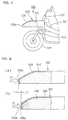
- Fig. 7 is a side view of a shock absorbing construction for motorcycles in the related art.
- a shock absorbing member 105 is disposed upwardly of the front wheel 104 by mounting a fork 103 on the head pipe 102 provided on a vehicle body frame 101 of a motorcycle 100, mounting a front wheel 104 on the fork 103, and mounting a deforming element (hereinafter referred to as "shock absorbing member") 105 at the front end of the vehicle body frame 101.
- the shock absorbing member 105 is manufactured by filling foam material 108 in a hollow portion 107 of a frame body 106.
- Fig. 8(a), (b) are an explanatory drawing showing the operation of the shock absorbing construction for motorcycles of the related art.
- the foam material 108 can be collapsed easily. Therefore, in order to absorb an impact force by means of the foam material 108 with a large amount of foaming space, it is required to increase the size of the foam material 108 to ensure the increased amount of collapse of the foam material 108. As a consequent, the dimensional standard of the shock absorbing member increases too much and thus it is difficult to put it into practical use.
- the invention according to Claim 1 is a shock absorbing construction for motorcycles including a shock absorbing member projecting from the vehicle body, and allowing the shock absorbing member to absorb an impact force by being collapsed, characterized in that the shock absorbing member comprises a plurality of cavities and a reinforcing rib for dividing the adjacent cavities, and all or some of these reinforcing ribs are formed with a thinner portion.
- the shock absorbing member comprises a plurality of cavities and a reinforcing rib for dividing the adjacent cavities, and all or some of these reinforcing ribs are formed with a thinner portion.
- providing a plurality of cavities helps to accommodate the reinforcing ribs in these cavities when the shock absorbing member is collapsed. Therefore, the sufficient amount of collapse of the shock absorbing member is ensured.
- Fig. 1 is a side view of a motorcycle mainly comprising a shock absorbing construction according to the present invention.
- the motorcycle 10 is a scooter type vehicle comprising a vehicle body frame 11, a front fork 12 mounted on a head pipe 11a of the vehicle body frame 11, a front wheel 13 mounted on the front fork 12, a steering handle 14 connected to the front fork 12, a swing unit 15 (an engine 15a, a transmission mechanism 15b) mounted at the rear portion of the vehicle body frame 11, a rear wheel 16 mounted on the rear portion of the swing unit 15, a seat 17 disposed at the rear top of the vehicle body frame 11, a front cover 18a for covering the front portion of the head pipe 11a, a center cover 18b extending rearward from the front cover 18a for covering the center of the vehicle body frame 11, a side cover 18c extending rearward from the center cover 18b for covering the rear portion of the vehicle body frame 11, and a shock absorbing structure 20 according to the present invention provided on the front cover 18a.
- the shock absorbing construction 20 comprises a frame body 22 of a shock absorbing member 21 mounted on the front cover 18a by means of, for example, tightening means (not shown), and a plurality of reinforcing ribs 30... provided in a space 25 in the frame body 22.
- the frame body 22 comprises a ceiling wall 23 bent generally at the center into an inverted V-shape, and a peripheral wall 24 provided around the periphery of the ceiling wall 23, and a rear portion 24d of the peripheral wall 24 is mounted to the front cover 18a.
- the shock absorbing member 21 is a resin member projecting frontward from the vehicle body, or from the front wheel 13, by the distance L2. In this arrangement, the shock absorbing member 21 can absorb the impact by being collapsed when the motorcycle 10 comes into collision with an obstruction by any chance.
- the occupant is protected form the impact by the shock absorbing member 21, which absorbs an impact by being collapsed.
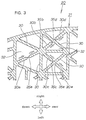
- Fig. 2 is a cross sectional view taken along the line 2-2 in Fig. 1.
- the peripheral wall 24 of the frame body 22 is a wall portion formed generally in U-shape in cross section, comprising a front wall 24a extending linearly in the direction of the width along the front end of the ceiling wall 23 (See also Fig. 1), a left side wall 24b extending rearward from the left end of the front wall 24a and being curved in part (front end portion) thereof, a right side wall 24c extending rearward from the right end of the front wall 24a and being curved in part (front end portion) thereof, and the rear wall 24d connecting the rear ends of the left and right side walls 24b and 24c and being curved corresponding to the configuration of the front cover 18a.
- the shock absorbing member 21 is a construction in which a plurality of reinforcing ribs 30... are provided in the space 25 of the above-described frame body 22, the reinforcing ribs 30... divide the interior of the frame body 22 into a plurality of cavities 32..., and some of the reinforcing ribs 30a-30g out of these reinforcing ribs 30... are formed respectively with thinner portions 35a-35g.
- Arranging the plurality of reinforcing ribs 30... so that the cavities 32...are formed into generally triangular shape as shown in Fig. 2 helps the frame body 22 to have a desired strength.
- the positions to arrange the reinforcing ribs 30... are not limited to the positions shown in Fig. 2, and they may be changed arbitrary according to the strength required for the shock absorbing member 21.
- the thinner portions 35a-35g is formed, for example, by the steps of selecting suitable reinforcing ribs 30a-30g out of the reinforcing ribs 30... that are subjected to a compressive load, and then forming the thinner portion 35a-35g on the selected reinforcing ribs 30a-30g respectively.
- the reinforcing ribs 30a-30g are provided on the right side and the left side of the shock absorbing member 21 so as to be symmetric with respect to a axle 37, and the thinner portions 35a-35g are provided on the left and right reinforcing ribs 30a-30g.
- reinforcing ribs 30a-30g on the right side and of the reinforcing ribs 30a-30g on the left side are the same, only the reinforcing ribs 30a-30g on the right side are described and the description of the reinforcing ribs 30a-30g on the left side is omitted.
- Fig. 3 is an enlarged view of the portion 3 in Fig. 2 showing a state in which the thinner portion 35a is formed at the center of the reinforcing rib 30a; the thinner portion 35b is formed at the rear end of the reinforcing rib 30b (or the portion to be joined to the reinforcing rib 30); the thinner portion 35c is formed at the front end of the reinforcing rib 30c (or the portion to be joined to the reinforcing rib 30), the thinner portion 35d is formed at the rear end of the reinforcing rib 30d (or the portion to be joined to the reinforcing rib 30); the thinner portion 35e is formed at the front end of the reinforcing rib 30e (or the portion to be joined to the reinforcing rib 30).
- the compressive force acts on these reinforcing ribs 30a-30g in the axial direction as shown by the arrows. Therefore, by forming the thinner portions 35a-35g on the reinforcing ribs 30a-30g, the thinner portions 35a-35g may be broken or deformed effectively.
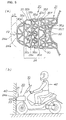
- Fig. 4(a), (b) are explanatory drawings showing the first operation of the shock absorbing construction for motorcycles according to the present invention.
- an impact force F1 acts on the tip of the reinforcing rib 30a as shown by the arrow (1), and a compressive force acts on the reinforcing rib 30a as shown by the arrow (2).
- a compressive force acts on the reinforcing rib 30b as shown by the arrow (3), and a compressive force acts on the reinforcing rib 30c as shown by the arrow (4).
- a compressive force acts on the reinforcing rib 30d as shown by the arrow (5), and a compressive force acts on the reinforcing rib 30e as shown by the arrow (6).
- Fig. 5 (a), (b) are explanatory drawings showing the second operation of the shock absorbing construction for motorcycles according to the present invention
- the thinner portion 35a of the reinforcing rib 30a, the thinner portion 35b of the reinforcing rib 30b, the thinner portion 35c of the reinforcing rib 30c, the thinner portion 35d of the reinforcing rib 30d, the thinner portion 35e of the reinforcing rib 30e, the thinner portion 35f of the reinforcing rib 30f, and the thinner portion 35g of the reinforcing rib 30g are broken.
- Breakage of the respective thinner portions 35a-35g removes the support by the reinforcing ribs 30a-30g. Therefore, the load can be concentrated on other reinforcing ribs 30..., and thus other reinforcing ribs 30... may be collapsed to the state shown in the figure.
- the thinner portions 35a-35g are provided generally over the whole area of a central portion 26 of the shock absorbing member 21, the whole area of the central portion 26 of the shock absorbing member 21 can be collapsed effectively, thereby ensuring a large amount of collapse L2 of the shock absorbing member 21.
- the increased amount of collapse L2 (shown in (a)) of the shock absorbing member 21 contributes to absorb an impact force F sufficiently when the front end 24a of the shock absorbing member 21 comes into collision with the obstruction 40, and thus a occupant 42 may be protected from the impact force F.
- the shock absorbing member 21 comprises the plurality of cavities 32..., and the reinforcing ribs 30...for dividing the adjacent cavities 32, 32, and the thinner portions 35a-35g are formed on some of the reinforcing ribs 30a-30g out of these reinforcing ribs 30....
- the thinner portions 35a-35g formed on the reinforcing ribs 30a-30g can adjust the strength of the reinforcing ribs 30a-30g. Therefore, the strength of the shock absorbing member 21, or the extent of collapse can be suitably adjusted according to the impact force.
- the shock absorbing member 21 can be formed in dimensions that are suitable for practical use, and simultaneously, the impact force can be absorbed sufficiently.
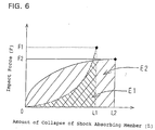
- Fig. 6 is a graph showing a relation between an impact force and the amount of collapse in the shock absorbing construction according to the present invention.
- the graph representing the case where a shock absorbing member according to the related art is collapsed in a dashed line is shown as a "comparative example", and the graph representing the case where a shock absorbing member according to the present invention is collapsed in a solid line is shown as an "embodiment”.
- the vertical axis represents an impact force (F)
- the lateral axis represents the amount of collapse (L) of the shock absorbing member.
- the comparative example shows that the amount of collapse of the shock absorbing member is as small as L1, and the graph in a dashed line represents a concave curve. Therefore, the amount of impact energy that can be absorbed is small in the area E1 surrounded by 0-F1-L1, where it is difficult to protect the occupant sufficiently from the impact force.
- the amount of collapse of the shock absorbing member is as large as L2, and the graph in a solid line represents a convex curve. Therefore, the amount of impact energy that can be absorbed is large in the area E2 surrounded by 0-F2-L2, where the occupants can be protected sufficiently from the impact force.
- shock absorbing member 21 is formed of resin
- shock absorbing member 21 is attached at the front end of the vehicle body.
- the same effect can be achieved even when the shock absorbing member 21 is mounted at the rear end or at the left and right sides of the vehicle body.
- the shock absorbing member according to Claim 1 is provided with a plurality of cavities and reinforcing ribs for dividing the adjacent cavities, and all or some of the reinforcing ribs are formed with thinner portions.
- Provision of thinner portions for all or some of the reinforcing ribs enables to adjust the strength of the reinforcing rib. Therefore, the strength of the shock absorbing member can be suitably adjusted according to the impact force.
- the dimensions of the shock absorbing member can be selected to be suitable for practical use, and simultaneously, an impact force can be absorbed sufficiently.
- a shock absorbing member 21 comprises a plurality of cavities 35... and reinforcing ribs 30... for dividing adjacent cavities 35, 35, and all or some 30a-30g of these reinforcing ribs 30...are formed with thinner portions 35a-35g respectively.
- a shock absorbing member 21 projecting forward from the front wheel 13 is provided so that the shock absorbing member 21 absorbs the impact by being collapsed.
Landscapes
- Engineering & Computer Science (AREA)
- Mechanical Engineering (AREA)
- Vibration Dampers (AREA)
- Body Structure For Vehicles (AREA)
Abstract
Description
- The present invention relates to a shock absorbing construction for motorcycles in which a shock absorbing member projecting from the vehicle body is provided so that the shock absorbing member absorbs the impact by being collapsed.
- Fig. 7 is a side view of a shock absorbing construction for motorcycles in the related art.
- A
shock absorbing member 105 is disposed upwardly of thefront wheel 104 by mounting afork 103 on thehead pipe 102 provided on avehicle body frame 101 of amotorcycle 100, mounting afront wheel 104 on thefork 103, and mounting a deforming element (hereinafter referred to as "shock absorbing member") 105 at the front end of thevehicle body frame 101. - The
shock absorbing member 105 is manufactured by fillingfoam material 108 in a hollow portion 107 of aframe body 106. - Fig. 8(a), (b) are an explanatory drawing showing the operation of the shock absorbing construction for motorcycles of the related art.
- In (a), when a motorcycle 100 (shown in Fig. 7) comes into collision with an obstruction, the
tip portion 105a of theshock absorbing member 105 hits the obstruction, and an impact force F1 generated by collision acts on thetip portion 105a as shown by the arrow. - In (b), when an impact force F1 acts on the tip portion 108a of the
foam material 108, the tip portion 108a will be collapsed. Accordingly, by thetip portion 105a of theshock absorbing material 105 being collapsed as much as the amount of collapse L1, an impact force F1 is absorbed to protect the occupant. - Incidentally, when the tip potion 108a of the
foam material 108 is collapsed, the space in thefoam material 108 is decreased, and thus it resists being collapsed. Therefore, when the foaming space is too small, it is difficult to ensure the sufficient amount of collapse of theshock absorbing member 105, and thus an impact force cannot be absorbed sufficiently. - In order to absorb an impact force sufficiently, it is conceivable to increase the foaming space in the
foam material 108 so that the amount of collapse of thefoam material 108 is also increased. - However, when the forming space in the
foam material 108 is too much, thefoam material 108 can be collapsed easily. Therefore, in order to absorb an impact force by means of thefoam material 108 with a large amount of foaming space, it is required to increase the size of thefoam material 108 to ensure the increased amount of collapse of thefoam material 108. As a consequent, the dimensional standard of the shock absorbing member increases too much and thus it is difficult to put it into practical use. - Accordingly, it is an object of the present invention to provide a shock absorbing construction for motorcycles that has a dimensional standard suitable for practical use and can absorb the impact force sufficiently.
- In order to achieve the object described above, the invention according to
Claim 1 is a shock absorbing construction for motorcycles including a shock absorbing member projecting from the vehicle body, and allowing the shock absorbing member to absorb an impact force by being collapsed, characterized in that the shock absorbing member comprises a plurality of cavities and a reinforcing rib for dividing the adjacent cavities, and all or some of these reinforcing ribs are formed with a thinner portion. - The shock absorbing member comprises a plurality of cavities and a reinforcing rib for dividing the adjacent cavities, and all or some of these reinforcing ribs are formed with a thinner portion. By forming a thinner portion on all or some of the reinforcing ribs, the strength of the reinforcing ribs can be controlled. Therefore, the strength of the shock absorbing member can be adequately adjusted for the impact force.
- In addition, providing a plurality of cavities helps to accommodate the reinforcing ribs in these cavities when the shock absorbing member is collapsed. Therefore, the sufficient amount of collapse of the shock absorbing member is ensured.
- Hereinafter, a preferred embodiment of the present invention will be described with reference to the accompanying drawings, in which:
- Fig. 1 is a side view of a motorcycle comprising a shock absorbing construction according to the present invention.
- Fig. 2 is a cross sectional view taken along the line 2-2 in Fig. 1.
- Fig. 3 is an enlarged view showing the
portion 3 in Fig. 2. - Fig. 4 is an explanatory drawing showing the first operation of the shock absorbing construction for motorcycles according to the present invention.
- Fig. 5 is an explanatory drawing showing the second operation of the shock absorbing construction for motorcycles according to the present invention.
- Fig. 6 is a graph representing a relation between an impact force and the amount of collapse in the shock absorbing construction according to the present invention.
- Fig. 7 is a side view of the shock absorbing construction for motorcycles of the related art.
- Fig. 8 is an explanatory drawing showing the operation of the shock absorbing construction for motorcycles of the related art.
-
- Referring now to the attached drawings, an embodiment of the present invention will be described. The drawing should be oriented so that the reference numerals can be viewed in the right way.
- Fig. 1 is a side view of a motorcycle mainly comprising a shock absorbing construction according to the present invention.
- The
motorcycle 10 is a scooter type vehicle comprising avehicle body frame 11, afront fork 12 mounted on ahead pipe 11a of thevehicle body frame 11, afront wheel 13 mounted on thefront fork 12, asteering handle 14 connected to thefront fork 12, a swing unit 15 (anengine 15a, atransmission mechanism 15b) mounted at the rear portion of thevehicle body frame 11, arear wheel 16 mounted on the rear portion of theswing unit 15, aseat 17 disposed at the rear top of thevehicle body frame 11, afront cover 18a for covering the front portion of thehead pipe 11a, acenter cover 18b extending rearward from thefront cover 18a for covering the center of thevehicle body frame 11, aside cover 18c extending rearward from thecenter cover 18b for covering the rear portion of thevehicle body frame 11, and ashock absorbing structure 20 according to the present invention provided on thefront cover 18a. Theshock absorbing construction 20 comprises aframe body 22 of ashock absorbing member 21 mounted on thefront cover 18a by means of, for example, tightening means (not shown), and a plurality of reinforcingribs 30... provided in aspace 25 in theframe body 22. - The
frame body 22 comprises aceiling wall 23 bent generally at the center into an inverted V-shape, and aperipheral wall 24 provided around the periphery of theceiling wall 23, and arear portion 24d of theperipheral wall 24 is mounted to thefront cover 18a. - It is also applicable to mount the
frame body 22 to thefront cover 18a and to thevehicle body frame 11, whereby theshock absorbing member 21 can be mounted on the vehicle body more firmly. - The
shock absorbing member 21 is a resin member projecting frontward from the vehicle body, or from thefront wheel 13, by the distance L2. In this arrangement, theshock absorbing member 21 can absorb the impact by being collapsed when themotorcycle 10 comes into collision with an obstruction by any chance. - As described above, the occupant is protected form the impact by the
shock absorbing member 21, which absorbs an impact by being collapsed. - Fig. 2 is a cross sectional view taken along the line 2-2 in Fig. 1.
- The
peripheral wall 24 of theframe body 22 is a wall portion formed generally in U-shape in cross section, comprising afront wall 24a extending linearly in the direction of the width along the front end of the ceiling wall 23 (See also Fig. 1), aleft side wall 24b extending rearward from the left end of thefront wall 24a and being curved in part (front end portion) thereof, aright side wall 24c extending rearward from the right end of thefront wall 24a and being curved in part (front end portion) thereof, and therear wall 24d connecting the rear ends of the left andright side walls front cover 18a. - Providing the
peripheral wall 24 around theceiling wall 23 in this way defines thespace 25 in theframe body 22. - The
shock absorbing member 21 is a construction in which a plurality of reinforcingribs 30... are provided in thespace 25 of the above-describedframe body 22, the reinforcingribs 30... divide the interior of theframe body 22 into a plurality ofcavities 32..., and some of the reinforcingribs 30a-30g out of these reinforcingribs 30... are formed respectively withthinner portions 35a-35g. - Arranging the plurality of reinforcing
ribs 30... so that thecavities 32...are formed into generally triangular shape as shown in Fig. 2 helps theframe body 22 to have a desired strength.. - The positions to arrange the reinforcing
ribs 30... are not limited to the positions shown in Fig. 2, and they may be changed arbitrary according to the strength required for theshock absorbing member 21. - The
thinner portions 35a-35g is formed, for example, by the steps of selecting suitable reinforcingribs 30a-30g out of the reinforcingribs 30... that are subjected to a compressive load, and then forming thethinner portion 35a-35g on the selected reinforcingribs 30a-30g respectively. - In other words, the reinforcing
ribs 30a-30g are provided on the right side and the left side of theshock absorbing member 21 so as to be symmetric with respect to aaxle 37, and thethinner portions 35a-35g are provided on the left and right reinforcingribs 30a-30g. - According to the
shock absorbing member 21, when an impact force F acts on thefront wall 24a as shown by an outline arrow, a compressive force acts in the direction of the axis of the reinforcingribs 30a-30g on the right side, and a compressive force acts in the direction of the axis of the reinforcingribs 30a-30g on the left side. - Since the construction of the reinforcing
ribs 30a-30g on the right side and of the reinforcingribs 30a-30g on the left side are the same, only the reinforcingribs 30a-30g on the right side are described and the description of the reinforcingribs 30a-30g on the left side is omitted. - Fig. 3 is an enlarged view of the
portion 3 in Fig. 2 showing a state in which thethinner portion 35a is formed at the center of the reinforcingrib 30a; thethinner portion 35b is formed at the rear end of the reinforcingrib 30b (or the portion to be joined to the reinforcing rib 30); thethinner portion 35c is formed at the front end of the reinforcingrib 30c (or the portion to be joined to the reinforcing rib 30), thethinner portion 35d is formed at the rear end of the reinforcingrib 30d (or the portion to be joined to the reinforcing rib 30); thethinner portion 35e is formed at the front end of the reinforcingrib 30e (or the portion to be joined to the reinforcing rib 30). - When the impact force F acts on the
front wall 24a (shown in Fig. 2) of theshock absorbing member 21, the compressive force acts on these reinforcingribs 30a-30g in the axial direction as shown by the arrows. Therefore, by forming thethinner portions 35a-35g on the reinforcingribs 30a-30g, thethinner portions 35a-35g may be broken or deformed effectively. - The operation of the
shock absorbing construction 20 according to the present invention as described above will now be described. - Fig. 4(a), (b) are explanatory drawings showing the first operation of the shock absorbing construction for motorcycles according to the present invention.
- In (a), the
front end 24a of theshock absorbing member 21 comes into collision with anobstruction 40 during traveling of themotorcycle 10. As a consequent, an impact force F acts on thefront end 24a of theshock absorbing member 21. - In (b), an impact force F1 acts on the tip of the reinforcing
rib 30a as shown by the arrow (1), and a compressive force acts on the reinforcingrib 30a as shown by the arrow (2). Then, a compressive force acts on the reinforcingrib 30b as shown by the arrow (3), and a compressive force acts on the reinforcingrib 30c as shown by the arrow (4). Concurrently, a compressive force acts on the reinforcingrib 30d as shown by the arrow (5), and a compressive force acts on the reinforcingrib 30e as shown by the arrow (6). - Fig. 5 (a), (b) are explanatory drawings showing the second operation of the shock absorbing construction for motorcycles according to the present invention
- In (a), on the right side, the
thinner portion 35a of the reinforcingrib 30a, thethinner portion 35b of the reinforcingrib 30b, thethinner portion 35c of the reinforcingrib 30c, thethinner portion 35d of the reinforcingrib 30d, thethinner portion 35e of the reinforcingrib 30e, thethinner portion 35f of the reinforcingrib 30f, and thethinner portion 35g of the reinforcingrib 30g are broken. - Concurrently, the respective
thinner portions 35a-35g of the reinforcingribs 30a-30g on the left side are also broken as in the case of the right side. - Breakage of the respective
thinner portions 35a-35g removes the support by the reinforcingribs 30a-30g. Therefore, the load can be concentrated on other reinforcingribs 30..., and thus other reinforcingribs 30... may be collapsed to the state shown in the figure. - Since the
thinner portions 35a-35g are provided generally over the whole area of acentral portion 26 of theshock absorbing member 21, the whole area of thecentral portion 26 of theshock absorbing member 21 can be collapsed effectively, thereby ensuring a large amount of collapse L2 of theshock absorbing member 21. - In (b), the increased amount of collapse L2 (shown in (a)) of the
shock absorbing member 21 contributes to absorb an impact force F sufficiently when thefront end 24a of theshock absorbing member 21 comes into collision with theobstruction 40, and thus a occupant 42 may be protected from the impact force F. - As described above, the
shock absorbing member 21 comprises the plurality ofcavities 32..., and the reinforcingribs 30...for dividing theadjacent cavities thinner portions 35a-35g are formed on some of the reinforcingribs 30a-30g out of these reinforcingribs 30.... - The
thinner portions 35a-35g formed on the reinforcingribs 30a-30g can adjust the strength of the reinforcingribs 30a-30g. Therefore, the strength of theshock absorbing member 21, or the extent of collapse can be suitably adjusted according to the impact force. - In addition, provision of the plurality of
cavities 32...contributes to ensure sufficient amount of collapse L2 of theshock absorbing member 21. - Since the extent of collapse of the
shock absorbing member 21 can be adjusted to ensure the amount of collapse L2 as is described thus far, theshock absorbing member 21 can be formed in dimensions that are suitable for practical use, and simultaneously, the impact force can be absorbed sufficiently. - Fig. 6 is a graph showing a relation between an impact force and the amount of collapse in the shock absorbing construction according to the present invention.
- The graph representing the case where a shock absorbing member according to the related art is collapsed in a dashed line is shown as a "comparative example", and the graph representing the case where a shock absorbing member according to the present invention is collapsed in a solid line is shown as an "embodiment". The vertical axis represents an impact force (F), and the lateral axis represents the amount of collapse (L) of the shock absorbing member.
- The comparative example shows that the amount of collapse of the shock absorbing member is as small as L1, and the graph in a dashed line represents a concave curve. Therefore, the amount of impact energy that can be absorbed is small in the area E1 surrounded by 0-F1-L1, where it is difficult to protect the occupant sufficiently from the impact force.
- The reason why the graph in a dashed line represents a concave curve here is that the shock absorbing member (foam material) in the comparative example can be collapsed by a relatively small impact force.
- In the embodiment, the amount of collapse of the shock absorbing member is as large as L2, and the graph in a solid line represents a convex curve. Therefore, the amount of impact energy that can be absorbed is large in the area E2 surrounded by 0-F2-L2, where the occupants can be protected sufficiently from the impact force.
- The reason why the graph in a solid line represents a convex curve here is that the shock absorbing member in the embodiment is collapsed by a suitable impact force.
- In the embodiment described above, the case where some of the reinforcing
ribs 30a-30g out of the reinforcingribs 30... are formed withthinner portions 35a-35g respectively is described. However, it is not limited thereto, and is also applicable to form a thinner portion for all the reinforcingribs 30.... The locations for forming thethinner portions 35a-35g may be determined as appropriate. - Though an example in which the
shock absorbing member 21 is formed of resin is described in the embodiment described above, it is also possible to form it of other materials, such as aluminum alloy, steel, or the like. - In the embodiment described above, an example in which the
shock absorbing member 21 is attached at the front end of the vehicle body is shown. However, the same effect can be achieved even when theshock absorbing member 21 is mounted at the rear end or at the left and right sides of the vehicle body. - The present invention in the arrangement described above provides the following advantages.
- The shock absorbing member according to
Claim 1 is provided with a plurality of cavities and reinforcing ribs for dividing the adjacent cavities, and all or some of the reinforcing ribs are formed with thinner portions. - Provision of thinner portions for all or some of the reinforcing ribs enables to adjust the strength of the reinforcing rib. Therefore, the strength of the shock absorbing member can be suitably adjusted according to the impact force.
- In addition, provision of a plurality of cavities enables to accommodate the reinforcing ribs in these cavities when the shock absorbing member is collapsed. Therefore, the sufficient amount of collapse of the shock absorbing member is ensured.
- As is described thus far, since the extent of collapse of the shock absorbing member can be adjusted to establish the amount of collapse, the dimensions of the shock absorbing member can be selected to be suitable for practical use, and simultaneously, an impact force can be absorbed sufficiently.
- In summary it is an object to provide a shock absorbing construction for motorcycles that has a dimensional standard suitable for practical use and can absorb the impact sufficiently.
- To achieve this, a
shock absorbing member 21 comprises a plurality of cavities 35... and reinforcingribs 30... for dividing adjacent cavities 35, 35, and all or some 30a-30g of these reinforcingribs 30...are formed withthinner portions 35a-35g respectively. Ashock absorbing member 21 projecting forward from thefront wheel 13 is provided so that theshock absorbing member 21 absorbs the impact by being collapsed.
Claims (1)
- A shock absorbing construction for motorcycles including a shock absorbing member (21) projecting from the vehicle body (11), and allowing the shock absorbing member (21) to absorb an impact force by being collapsed, characterized in that the shock absorbing member (21) comprises a plurality of cavities (32...) and a reinforcing rib (30...) for dividing the adjacent cavities (32...), and all or some (30a - 30g) of these reinforcing ribs (30...) are formed with a thinner portion (35a - 35g).
Applications Claiming Priority (2)
| Application Number | Priority Date | Filing Date | Title |
|---|---|---|---|
| JP2000396770A JP4394272B2 (en) | 2000-12-27 | 2000-12-27 | Shock absorption structure of motorcycle |
| JP2000396770 | 2000-12-27 |
Publications (3)
| Publication Number | Publication Date |
|---|---|
| EP1219530A2 true EP1219530A2 (en) | 2002-07-03 |
| EP1219530A3 EP1219530A3 (en) | 2003-08-13 |
| EP1219530B1 EP1219530B1 (en) | 2007-08-08 |
Family
ID=18862006
Family Applications (1)
| Application Number | Title | Priority Date | Filing Date |
|---|---|---|---|
| EP01129726A Expired - Lifetime EP1219530B1 (en) | 2000-12-27 | 2001-12-13 | Shock absorbing construction for motorcycles |
Country Status (7)
| Country | Link |
|---|---|
| US (1) | US6547294B2 (en) |
| EP (1) | EP1219530B1 (en) |
| JP (1) | JP4394272B2 (en) |
| CN (1) | CN1198743C (en) |
| DE (1) | DE60129783T2 (en) |
| ES (1) | ES2291266T3 (en) |
| TW (1) | TWI243778B (en) |
Families Citing this family (10)
| Publication number | Priority date | Publication date | Assignee | Title |
|---|---|---|---|---|
| JP4472898B2 (en) * | 2001-08-07 | 2010-06-02 | 株式会社イノアックコーポレーション | Shock absorber for motorcycle |
| DE10307974B4 (en) * | 2002-03-13 | 2010-12-02 | Peguform Gmbh | Bumper with deformation element |
| US20070256882A1 (en) * | 2006-05-05 | 2007-11-08 | Bombardier Recreational Products Inc. | Three-Wheel Vehicle |
| JP2011530054A (en) * | 2008-08-07 | 2011-12-15 | ビーエーエスエフ ソシエタス・ヨーロピア | Energy absorption structure |
| CN102442380B (en) * | 2010-10-08 | 2013-12-25 | 苏州益高电动车辆制造有限公司 | Anti-collision safety device for vehicles |
| US9241850B2 (en) | 2011-09-02 | 2016-01-26 | Ferno-Washington, Inc. | Litter support assembly for medical care units having a shock load absorber and methods of their use |
| US10647283B2 (en) * | 2015-11-27 | 2020-05-12 | Kyoraku Co., Ltd. | Shock absorber |
| US11117637B2 (en) | 2018-07-25 | 2021-09-14 | Harley-Davidson Motor Company Group, LLC | Motorcycle frame |
| JP7715618B2 (en) * | 2021-12-10 | 2025-07-30 | 株式会社ダイセル | shock absorbing device |
| US20250074346A1 (en) * | 2023-09-01 | 2025-03-06 | Ford Global Technologies, Llc | Vehicle bumper |
Family Cites Families (10)
| Publication number | Priority date | Publication date | Assignee | Title |
|---|---|---|---|---|
| GB197809A (en) * | 1922-04-05 | 1923-05-24 | Arthur George Green | Improvements in the preparation of azo compounds |
| US4311335A (en) * | 1980-04-24 | 1982-01-19 | Henry F. Winiecki | Crash resistant motorcycle |
| SE427342B (en) * | 1980-07-14 | 1983-03-28 | Bjorn Heggkvist | DEVICE OF A MOTORCYCLE TO PROTECT THE DRIVER DURING A COLLISION |
| US4413856A (en) * | 1981-08-07 | 1983-11-08 | General Motors Corporation | Hardbar energy absorbing bumper system for vehicles |
| FR2704286B1 (en) * | 1993-04-23 | 1995-06-02 | Gec Alsthom Transport Sa | Shock absorption device. |
| US5636866A (en) * | 1994-09-21 | 1997-06-10 | Kojima Press Industry Co., Ltd. | Shock absorbing structure for motor vehicle |
| US5700545A (en) * | 1995-05-31 | 1997-12-23 | The Oakwood Group | Energy absorbing structure |
| DE19629879A1 (en) * | 1996-07-24 | 1998-01-29 | Bayerische Motoren Werke Ag | Vehicle frame with access, especially for a two-wheeler |
| US6199942B1 (en) * | 1998-02-04 | 2001-03-13 | Oakwood Energy Management, Inc. | Modular energy absorbing assembly |
| US6062632A (en) * | 1998-03-20 | 2000-05-16 | Solectria Corporation | Vehicle body collision energy absorption system |
-
2000
- 2000-12-27 JP JP2000396770A patent/JP4394272B2/en not_active Expired - Fee Related
-
2001
- 2001-11-16 TW TW090128471A patent/TWI243778B/en not_active IP Right Cessation
- 2001-12-13 DE DE60129783T patent/DE60129783T2/en not_active Expired - Fee Related
- 2001-12-13 ES ES01129726T patent/ES2291266T3/en not_active Expired - Lifetime
- 2001-12-13 EP EP01129726A patent/EP1219530B1/en not_active Expired - Lifetime
- 2001-12-27 CN CNB011439602A patent/CN1198743C/en not_active Expired - Fee Related
- 2001-12-27 US US10/026,783 patent/US6547294B2/en not_active Expired - Fee Related
Non-Patent Citations (1)
| Title |
|---|
| None |
Also Published As
| Publication number | Publication date |
|---|---|
| TWI243778B (en) | 2005-11-21 |
| CN1362342A (en) | 2002-08-07 |
| EP1219530A3 (en) | 2003-08-13 |
| JP4394272B2 (en) | 2010-01-06 |
| DE60129783D1 (en) | 2007-09-20 |
| JP2002193169A (en) | 2002-07-10 |
| EP1219530B1 (en) | 2007-08-08 |
| ES2291266T3 (en) | 2008-03-01 |
| DE60129783T2 (en) | 2007-12-06 |
| CN1198743C (en) | 2005-04-27 |
| US20020084658A1 (en) | 2002-07-04 |
| US6547294B2 (en) | 2003-04-15 |
Similar Documents
| Publication | Publication Date | Title |
|---|---|---|
| JP4478654B2 (en) | Body floor structure | |
| US6764099B2 (en) | Shock absorbing structure for vehicles | |
| JP4520055B2 (en) | Shock absorption structure for motorcycles | |
| EP1219530B1 (en) | Shock absorbing construction for motorcycles | |
| JP2005001430A (en) | Vehicle body front structure of automobile | |
| US10343721B2 (en) | Front vehicle body reinforcing structure | |
| JP2005178682A (en) | Body front structure of automobile | |
| JP2006290311A (en) | Body front structure | |
| JP5171285B2 (en) | Body front structure | |
| JP4676281B2 (en) | Vehicle flap | |
| JP4532003B2 (en) | Shock absorption structure for motorcycles | |
| JP4757757B2 (en) | Front bumper | |
| KR20200134493A (en) | Front vehicle body reinforcing structure | |
| JP2005178543A (en) | Vehicle front wheel support structure | |
| JP5772475B2 (en) | Body front structure | |
| JP4745516B2 (en) | Shock absorption structure of a motorcycle with a cabin | |
| JP5958790B2 (en) | Impact energy absorption type underlamp protector | |
| JP4908126B2 (en) | Front fender | |
| JP2008080881A (en) | Front bumper | |
| JP2000095117A (en) | Shock absorbing steering column device | |
| KR20220060950A (en) | The bumper structure for automobiles improved so that the collision performance can be sufficiently exhibited | |
| KR100406152B1 (en) | Impact absorption body reinforcement structure make use of reinforcement bar | |
| JP2013116706A (en) | Vehicle body rear structure | |
| JP2006321360A (en) | Bumper structure for vehicles | |
| KR19980031307A (en) | Shock-absorbing structure of vehicle engine mounting member |
Legal Events
| Date | Code | Title | Description |
|---|---|---|---|
| PUAI | Public reference made under article 153(3) epc to a published international application that has entered the european phase |
Free format text: ORIGINAL CODE: 0009012 |
|
| AK | Designated contracting states |
Kind code of ref document: A2 Designated state(s): AT BE CH CY DE DK ES FI FR GB GR IE IT LI LU MC NL PT SE TR |
|
| AX | Request for extension of the european patent |
Free format text: AL;LT;LV;MK;RO;SI |
|
| PUAL | Search report despatched |
Free format text: ORIGINAL CODE: 0009013 |
|
| AK | Designated contracting states |
Designated state(s): AT BE CH CY DE DK ES FI FR GB GR IE IT LI LU MC NL PT SE TR |
|
| AX | Request for extension of the european patent |
Extension state: AL LT LV MK RO SI |
|
| 17P | Request for examination filed |
Effective date: 20030723 |
|
| AKX | Designation fees paid |
Designated state(s): DE ES FR GB IT |
|
| GRAP | Despatch of communication of intention to grant a patent |
Free format text: ORIGINAL CODE: EPIDOSNIGR1 |
|
| GRAS | Grant fee paid |
Free format text: ORIGINAL CODE: EPIDOSNIGR3 |
|
| GRAA | (expected) grant |
Free format text: ORIGINAL CODE: 0009210 |
|
| AK | Designated contracting states |
Kind code of ref document: B1 Designated state(s): DE ES FR GB IT |
|
| RAP1 | Party data changed (applicant data changed or rights of an application transferred) |
Owner name: HONDA GIKEN KOGYO KABUSHIKI KAISHA |
|
| REG | Reference to a national code |
Ref country code: GB Ref legal event code: FG4D |
|
| REF | Corresponds to: |
Ref document number: 60129783 Country of ref document: DE Date of ref document: 20070920 Kind code of ref document: P |
|
| ET | Fr: translation filed | ||
| REG | Reference to a national code |
Ref country code: ES Ref legal event code: FG2A Ref document number: 2291266 Country of ref document: ES Kind code of ref document: T3 |
|
| PLBE | No opposition filed within time limit |
Free format text: ORIGINAL CODE: 0009261 |
|
| STAA | Information on the status of an ep patent application or granted ep patent |
Free format text: STATUS: NO OPPOSITION FILED WITHIN TIME LIMIT |
|
| 26N | No opposition filed |
Effective date: 20080509 |
|
| PGFP | Annual fee paid to national office [announced via postgrant information from national office to epo] |
Ref country code: IT Payment date: 20081220 Year of fee payment: 8 |
|
| PGFP | Annual fee paid to national office [announced via postgrant information from national office to epo] |
Ref country code: ES Payment date: 20090120 Year of fee payment: 8 Ref country code: FR Payment date: 20081212 Year of fee payment: 8 |
|
| PGFP | Annual fee paid to national office [announced via postgrant information from national office to epo] |
Ref country code: DE Payment date: 20081211 Year of fee payment: 8 |
|
| PGFP | Annual fee paid to national office [announced via postgrant information from national office to epo] |
Ref country code: GB Payment date: 20081210 Year of fee payment: 8 |
|
| GBPC | Gb: european patent ceased through non-payment of renewal fee |
Effective date: 20091213 |
|
| REG | Reference to a national code |
Ref country code: FR Ref legal event code: ST Effective date: 20100831 |
|
| PG25 | Lapsed in a contracting state [announced via postgrant information from national office to epo] |
Ref country code: FR Free format text: LAPSE BECAUSE OF NON-PAYMENT OF DUE FEES Effective date: 20091231 |
|
| PG25 | Lapsed in a contracting state [announced via postgrant information from national office to epo] |
Ref country code: DE Free format text: LAPSE BECAUSE OF NON-PAYMENT OF DUE FEES Effective date: 20100701 |
|
| PG25 | Lapsed in a contracting state [announced via postgrant information from national office to epo] |
Ref country code: GB Free format text: LAPSE BECAUSE OF NON-PAYMENT OF DUE FEES Effective date: 20091213 |
|
| PG25 | Lapsed in a contracting state [announced via postgrant information from national office to epo] |
Ref country code: IT Free format text: LAPSE BECAUSE OF NON-PAYMENT OF DUE FEES Effective date: 20091213 |
|
| REG | Reference to a national code |
Ref country code: ES Ref legal event code: FD2A Effective date: 20110405 |
|
| PG25 | Lapsed in a contracting state [announced via postgrant information from national office to epo] |
Ref country code: ES Free format text: LAPSE BECAUSE OF NON-PAYMENT OF DUE FEES Effective date: 20110323 |
|
| PG25 | Lapsed in a contracting state [announced via postgrant information from national office to epo] |
Ref country code: ES Free format text: LAPSE BECAUSE OF NON-PAYMENT OF DUE FEES Effective date: 20091214 |