EP1219529A2 - Vehicle front body structure - Google Patents
Vehicle front body structure Download PDFInfo
- Publication number
- EP1219529A2 EP1219529A2 EP01130718A EP01130718A EP1219529A2 EP 1219529 A2 EP1219529 A2 EP 1219529A2 EP 01130718 A EP01130718 A EP 01130718A EP 01130718 A EP01130718 A EP 01130718A EP 1219529 A2 EP1219529 A2 EP 1219529A2
- Authority
- EP
- European Patent Office
- Prior art keywords
- flanges
- web
- impact
- thickness
- impact absorbing
- Prior art date
- Legal status (The legal status is an assumption and is not a legal conclusion. Google has not performed a legal analysis and makes no representation as to the accuracy of the status listed.)
- Granted
Links
Images



Classifications
-
- B—PERFORMING OPERATIONS; TRANSPORTING
- B62—LAND VEHICLES FOR TRAVELLING OTHERWISE THAN ON RAILS
- B62D—MOTOR VEHICLES; TRAILERS
- B62D25/00—Superstructure or monocoque structure sub-units; Parts or details thereof not otherwise provided for
- B62D25/08—Front or rear portions
-
- B—PERFORMING OPERATIONS; TRANSPORTING
- B62—LAND VEHICLES FOR TRAVELLING OTHERWISE THAN ON RAILS
- B62D—MOTOR VEHICLES; TRAILERS
- B62D21/00—Understructures, i.e. chassis frame on which a vehicle body may be mounted
- B62D21/15—Understructures, i.e. chassis frame on which a vehicle body may be mounted having impact absorbing means, e.g. a frame designed to permanently or temporarily change shape or dimension upon impact with another body
- B62D21/152—Front or rear frames
Definitions
- This invention relates to a vehicle front body structure, and more particularly, to an energy absorbing structure primarily for protection of pedestrians' legs.
- This conventional front body structure is, however, designed to be an impact absorbing structure effective for collision between vehicles or collision between a vehicle and some construction such as an electric pole or a guardrail. And thus this impact absorbing structure is not intended for protection of objects to be protected including pedestrians (hereinafter referred to as "protection objects").
- the present invention provides a vehicle front body structure capable of protecting protection objects as well as offering protection in collision between vehicles.
- a vehicle front body structure which comprises: left and right side frames extending in the longitudinal direction of a vehicle body; left and right first impact absorbing members provided at front ends of the left and right side frames, respectively, for absorbing impact caused by collision with a vehicle; and second impact absorbing members provided at front ends of the left and right first impact absorbing members for absorbing impact caused by collision with an object to be protected, wherein each of the second impact absorbing members has a generally U-shaped cross-section and comprises an upper flange and a lower flange each having a front end and extending forward from respective one of the first impact absorbing members, and a web connecting the front ends of the upper and lower flanges, and the web has a thickness greater than those of the upper and lower flanges.
- an impact energy caused by collision between vehicles is thus absorbed by the first impact absorbing members buckled.
- the second impact absorbing member is buckled with the thinner upper and lower flanges buckled, preventing the buckling of the thicker web. That is, the web is made thicker to minimize the plastic deformation thereof.
- the upper and lower flanges are made thinner to promote plastic deformation of the flanges.
- the upper and lower flanges extending in the longitudinal direction allow longer distance and time period from the plastic deformation starting point to the plastic deformation end point, resulting in even and long-duration impact energy absorption. This causes plastic deformation to begin with a relatively small force and enables a reduced reactive force, thereby providing sufficient protection to a protection object in collision with the object.
- the upper and lower flanges extending forward of the first impact absorbing members are preferably inclined upward or downward; and an angle of inclination of the upper and lower flanges is preferably set at at least (T/L) radian in which T is the thickness of the flanges and L is the length of the flanges. That is, the upper and lower flanges are inclined at a predetermined angle with respect to a horizontal line so as to promote bending deformation of the flanges, increasing the responsivity, thereby further mitigating collision impact to a protection object.
- the bending deformation of the flanges can absorb more energy with a reduced stroke, allowing a space accommodating the second impact absorbing member to be smaller.
- a corner formed between the upper or lower flange and the web is preferably curved to have a radius of curvature set at three to five times the thickness of the flanges.
- the rounded corners between the flanges and the web allow the flanges to be smoothly deformed downward (or upward). It has been found that the radius of curvature less than three times the thickness of the flanges is disadvantageously too small to facilitate development of the corner.
- the radius of curvature more than five times the thickness of the flanges is too large to leave sufficient linear sections of the flanges, causing possible decrease in energy absorption efficiency due to increase in peak acceleration. Accordingly it is desirable to select the radius of curvature in a range from three to five times the thickness of the flanges.
- a vehicle front body structure has left and right side frames 11L, 11R (L indicates left and R indicates right. This applies hereinafter.), a bumper beam 12 extended between and fixed with a plurality of bolts 13 to the frames 11L, 11R, left and right first impact absorbing members 14L, 14R for absorbing impact of collision between vehicles, provided respectively at left and right end portions of the bumper beam 12 and at front end portions of the left and right side frames 11L, 11R, second impact absorbing members 15L, 15R for absorbing impact of collision with protection objects, provided at front portions of the left and right first impact absorbing members 14L, 14R, and a bumper face 16 covering those members.
- the bumper face 16 bends in a sufficient manner.
- the side frame 11L or 11R resists it, resulting in insufficient energy absorption.
- the first impact absorbing members 14L, 14R and the second impact absorbing members 15L, 15R are provided only at the front ends of the side frames 11L, 11R. This allows the impact absorption properties of the vehicle to be even in the transverse direction.
- FIG. 2 shows the first impact absorbing member 14L welded to the bumper beam 12, and the second impact absorbing member 15L for protection objects, welded to the first absorbing member 14L.
- the first absorbing member 14L is in a bellows-like shape so as to be buckled and plastically deformed when receiving a large impact from the left in the figure, thereby absorbing the impact energy.
- a sufficiently large opening 18 is provided in a front wall 17 of the first absorbing member 14L. The opening 18 serves as a hole for accommodating the second absorbing member 15L plastically deformed to a large extent as described later.
- the second absorbing member 15L is a cross-sectionally U-shaped member consisting of an upper flange 21 and a lower flange 22 extending forward of the first absorbing member 14L by length L, and a web 23 connecting the front ends of the upper and lower flanges 21, 22.
- the web 23 has a thickness greater than that of the upper and lower flanges 21, 22. Specifically, with the thickness of the flanges 21, 22 denoted by "T" and that of the web 23 by "W,” T ⁇ W.
- the second absorbing member 15L may be obtained by bending a blank of the thickness T with the reinforcement plate 24 of the thickness t welded thereto. Thus degree of freedom in processing is increased.
- the second absorbing member 15L may be produced by preparing a flat plate having thickness W at the middle and thickness T at the opposite ends in a rolling process and bending it.
- the web 23 first receives an external force and bends in a dogleg shape before the flanges 21, 22 do. More specifically, the opposite ends of the web 23 are supported on the flanges 21, 22 while the middle section of the web 23 is free, so that a horizontal external force applied to the web 23 causes the web 23 to be bent in a dogleg shape. Such bending occurs at a low acceleration (hereinafter referred to as a "G"). On the other hand, the subsequent buckling of the flanges 21, 22 occurs at a G significantly greater than that of the web 23.
- G low acceleration
- the G is lower in the former-half of plastic deformation of the second absorbing member, and greater in the latter-half (this will be described with reference to FIG. 5A). In order to improve impact energy absorption, it is required to make the G peak lower.
- the present invention suppresses deformation of the web 23 by providing the web 23 with a larger thickness.
- the flanges 21, 22 are made thinner to promote the plastic deformation thereof.
- the flanges 21, 22 are deformed in the overall range of plastic deformation, averaging the G, and thereby achieving a lower peak (See FIG. 5B).
- the upper and lower flanges 21, 22 are preferably inclined downward at an inclination angle of ⁇ radian, and a corner formed between the flange 21 and the web 23 is curved with a radius of curvature R as shown in the figure.
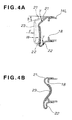
- FIGS. 4A and 4B illustrate the function of the upper and lower flanges 21, 22 with the inclination angle ⁇ and the curved corner.
- imaginary lines depict the second absorbing member 15L before deformation
- solid lines depict the middle of deformation.
- FIG. 4B shows the last stage of plastic deformation in which the flanges 21, 22 are drawn downward.
- the curves of curvature radius R See FIG. 3
- the curves of curvature radius R See FIG. 3
- the curves of curvature radius R See FIG. 3
- a large curvature facilitates development of the curve as shown in the figure.
- the radius of curvature R should be selected in a range from three to five times the thickness of the flanges. It has been confirmed that the radius of curvature R less than three times the thickness of the flanges is disadvantageously too small to enable easy development of the corners. The radius of curvature R more than five times the thickness of the flanges provides too large curves to leave sufficient linear sections of the flanges 21, 22, resulting in possible decrease in energy absorption efficiency due to an increased peak G.
- the radius of curvature R is selected in a range from three to five times the thickness of the flanges.
- angle of inclination ⁇ should be set at at least (T/L) radian in which T is the thickness of the flanges and L is the length of the flanges.
- the inclination angle ⁇ is set not less than (T/L) radian.
- the inclination angle ⁇ is set not greater than 5x(T/L) radian, and is preferably set at 3(T/L) radian.
- the inclination angle ⁇ greater than 5x(T/L) radian causes the flanges 21, 22 to be bendably deformed only at the front ends (intersecting points with the web 23) at the input of impact, resulting in less energy absorption.
- the inclination of (T/L) radian corresponds to that of the flanges 21, 22 with the front ends (intersections with the web 23) lowered (or raised) by T from a horizontal line.
- FIGS. 5A and 5B are comparative graphs illustrating impact absorption effects.
- the horizontal axis indicates stroke and the vertical axis indicates acceleration.
- FIG. 5A is of a comparative example with the flanges and web having the same thickness. It is found in the figure that the higher peak occurs in the last stage of a stroke.
- FIG. 5B is of the embodiment with the thinner flanges and the thicker web. It is found that the peak is lower.
- the expression "the first impact absorbing members are provided at front end portions of the side flames" includes both the case where the first absorbing members are directly provided at the front end portions of the side frames and the case where the first absorbing members are provided indirectly to the front portions of the side frames via the bumper beam or brackets.
- a vehicle front body structure having first impact absorbing members (14L, 14R) for absorbing impact caused by collision between vehicles and second impact absorbing members (15L, 15R) for absorbing impact caused by collision with an object to be protected.
- Each second impact absorbing member has a generally U-shape cross-section, consisting of upper and lower flanges (21, 22) extending forward from respective front end of the first impact absorbing members, and a web (23). The thickness of the web is made greater than those of the upper and lower flanges so that an impact energy produced by collision with a protection object is absorbed by buckling or plastic deformation of the upper and lower flanges, with minimized deformation of the thick web.
Landscapes
- Engineering & Computer Science (AREA)
- Chemical & Material Sciences (AREA)
- Combustion & Propulsion (AREA)
- Transportation (AREA)
- Mechanical Engineering (AREA)
- Body Structure For Vehicles (AREA)
Abstract
Description
Claims (4)
- A vehicle front body structure comprising:wherein each of said second impact absorbing members has a generally U-shaped cross-section and comprises an upper flange (21) and a lower flange (22) each having a front end and extending forward from respective one of said first impact absorbing members, and a web (23) connecting the front ends of said upper and lower flanges, and said web has a thickness greater than those of said upper and lower flanges.left and right side frames (11L, 11R) extending longitudenally of a vehicle body;left and right first impact absorbing members (14L, 14R) provided at front ends of said left and right side frames, respectively, for absorbing impact caused by collision with a vehicle; andsecond impact absorbing members (15L, 15R) provided at front ends of said left and right first impact absorbing members for absorbing impact caused by collision with an object to be protected,
- The front body structure of claim 1, wherein said upper and lower flanges (21, 22) extending forward of said first impact absorbing members (14L, 14R) are inclined upward or downward, and an angle of inclination () of said upper and lower flanges is set at at least (T/L) radian in which T is the thickness of said flanges and L is the length of said flanges.
- The front body structure of claim 1, wherein a corner formed between said upper or lower flange (21, 22) and said web (23) is curved to have a radius of curvature (R) set at three to five times the thickness of said flanges.
- The front body structure according to claim 2, wherein a corner formed between said upper or lower flange (21, 22) and said web (23) is curved to have a radius of curvature (R) set at three to five times the thickness of said flanges.
Applications Claiming Priority (2)
| Application Number | Priority Date | Filing Date | Title |
|---|---|---|---|
| JP2000395910A JP3540744B2 (en) | 2000-12-26 | 2000-12-26 | Vehicle front structure |
| JP2000395910 | 2000-12-26 |
Publications (3)
| Publication Number | Publication Date |
|---|---|
| EP1219529A2 true EP1219529A2 (en) | 2002-07-03 |
| EP1219529A3 EP1219529A3 (en) | 2003-11-05 |
| EP1219529B1 EP1219529B1 (en) | 2004-09-22 |
Family
ID=18861288
Family Applications (1)
| Application Number | Title | Priority Date | Filing Date |
|---|---|---|---|
| EP01130718A Expired - Lifetime EP1219529B1 (en) | 2000-12-26 | 2001-12-21 | Vehicle front body structure |
Country Status (3)
| Country | Link |
|---|---|
| EP (1) | EP1219529B1 (en) |
| JP (1) | JP3540744B2 (en) |
| DE (1) | DE60105747T2 (en) |
Families Citing this family (6)
| Publication number | Priority date | Publication date | Assignee | Title |
|---|---|---|---|---|
| JP4506499B2 (en) * | 2005-02-15 | 2010-07-21 | マツダ株式会社 | Front body structure of automobile |
| JP4583214B2 (en) * | 2005-03-28 | 2010-11-17 | 株式会社神戸製鋼所 | Automotive bumper structure |
| JP5016507B2 (en) * | 2008-01-30 | 2012-09-05 | 本田技研工業株式会社 | Vehicle front bumper device |
| DE102009049553A1 (en) | 2009-10-16 | 2011-04-21 | Hbpo Gmbh | Crash management system for mounting in motor vehicle to control consequences of collision with e.g. pedestrians, has carrier element whose area lies closer to vehicle than ends of crash boxes, where ends are directed away from vehicle |
| JP6623676B2 (en) * | 2015-10-23 | 2019-12-25 | スズキ株式会社 | Vehicle front structure |
| CN108001533A (en) * | 2017-11-22 | 2018-05-08 | 奇瑞汽车股份有限公司 | Front deck vehicle frame |
Family Cites Families (3)
| Publication number | Priority date | Publication date | Assignee | Title |
|---|---|---|---|---|
| NL1001169C2 (en) * | 1995-09-11 | 1997-03-13 | Hoogovens Staal Bv | Crash unit, sleeve-shaped part and method for manufacturing a tube sheath deformable by syrups. |
| US5876078A (en) * | 1997-01-21 | 1999-03-02 | Ford Global Technologies, Inc. | Bumper and front rail assembly for vehicle |
| JP3870503B2 (en) * | 1997-09-01 | 2007-01-17 | 日産自動車株式会社 | Automotive bumper structure |
-
2000
- 2000-12-26 JP JP2000395910A patent/JP3540744B2/en not_active Expired - Fee Related
-
2001
- 2001-12-21 DE DE60105747T patent/DE60105747T2/en not_active Expired - Lifetime
- 2001-12-21 EP EP01130718A patent/EP1219529B1/en not_active Expired - Lifetime
Also Published As
| Publication number | Publication date |
|---|---|
| DE60105747D1 (en) | 2004-10-28 |
| JP3540744B2 (en) | 2004-07-07 |
| EP1219529B1 (en) | 2004-09-22 |
| DE60105747T2 (en) | 2005-05-12 |
| EP1219529A3 (en) | 2003-11-05 |
| JP2002193054A (en) | 2002-07-10 |
Similar Documents
| Publication | Publication Date | Title |
|---|---|---|
| EP1816036B1 (en) | Impact absorbing member and vehicle bumper structure | |
| CA2245851C (en) | Front structure of car body, and method of absorbing impact by means of the front structure | |
| US5348114A (en) | Front chassis frame for automobile | |
| JP5329188B2 (en) | Bumper reinforcement | |
| WO2010007481A1 (en) | Pillar structure of vehicle and method for manufacturing the same | |
| EP2345560A1 (en) | Underrun prevention member for vehicle bumper beam | |
| US20040113463A1 (en) | Reinforced structure for rear part of front side rail in vehicle | |
| EP1676752A2 (en) | Bumper beam structure having support walls for center gusset | |
| JP2005145224A (en) | Vehicle hood structure | |
| KR960005860B1 (en) | Rear body structure of car | |
| EP1219529B1 (en) | Vehicle front body structure | |
| JP5207228B2 (en) | Inner panel for vehicle | |
| EP2200876B1 (en) | Vehicle inner panel | |
| JPH11321717A (en) | Fender structure | |
| JP5459054B2 (en) | Body parts for vehicles | |
| JP3617481B2 (en) | Auto body front structure | |
| JP7459687B2 (en) | Vehicle front body structure | |
| JP3136637B2 (en) | Energy absorber for vehicle bumper | |
| JPH0820297A (en) | Bumper reinforcement | |
| JP4036219B2 (en) | Automotive engine hood structure | |
| US7097221B2 (en) | Bumper having a roll-formed ridge | |
| JPH10278706A (en) | Bumper reinforcement mounting structure | |
| EP2428432B1 (en) | Front side vehicle body structure | |
| JP7826636B2 (en) | Vehicle cowl components | |
| US20260084751A1 (en) | Vehicle front structure |
Legal Events
| Date | Code | Title | Description |
|---|---|---|---|
| PUAI | Public reference made under article 153(3) epc to a published international application that has entered the european phase |
Free format text: ORIGINAL CODE: 0009012 |
|
| AK | Designated contracting states |
Kind code of ref document: A2 Designated state(s): AT BE CH CY DE DK ES FI FR GB GR IE IT LI LU MC NL PT SE TR |
|
| AX | Request for extension of the european patent |
Free format text: AL;LT;LV;MK;RO;SI |
|
| PUAL | Search report despatched |
Free format text: ORIGINAL CODE: 0009013 |
|
| AK | Designated contracting states |
Kind code of ref document: A3 Designated state(s): AT BE CH CY DE DK ES FI FR GB GR IE IT LI LU MC NL PT SE TR |
|
| AX | Request for extension of the european patent |
Extension state: AL LT LV MK RO SI |
|
| 17P | Request for examination filed |
Effective date: 20031219 |
|
| GRAP | Despatch of communication of intention to grant a patent |
Free format text: ORIGINAL CODE: EPIDOSNIGR1 |
|
| GRAS | Grant fee paid |
Free format text: ORIGINAL CODE: EPIDOSNIGR3 |
|
| AKX | Designation fees paid |
Designated state(s): DE FR GB |
|
| GRAA | (expected) grant |
Free format text: ORIGINAL CODE: 0009210 |
|
| AK | Designated contracting states |
Kind code of ref document: B1 Designated state(s): DE FR GB |
|
| REG | Reference to a national code |
Ref country code: GB Ref legal event code: FG4D |
|
| REG | Reference to a national code |
Ref country code: IE Ref legal event code: FG4D |
|
| REF | Corresponds to: |
Ref document number: 60105747 Country of ref document: DE Date of ref document: 20041028 Kind code of ref document: P |
|
| ET | Fr: translation filed | ||
| PLBE | No opposition filed within time limit |
Free format text: ORIGINAL CODE: 0009261 |
|
| STAA | Information on the status of an ep patent application or granted ep patent |
Free format text: STATUS: NO OPPOSITION FILED WITHIN TIME LIMIT |
|
| 26N | No opposition filed |
Effective date: 20050623 |
|
| PGFP | Annual fee paid to national office [announced via postgrant information from national office to epo] |
Ref country code: FR Payment date: 20061208 Year of fee payment: 6 |
|
| PGFP | Annual fee paid to national office [announced via postgrant information from national office to epo] |
Ref country code: GB Payment date: 20061220 Year of fee payment: 6 |
|
| GBPC | Gb: european patent ceased through non-payment of renewal fee |
Effective date: 20071221 |
|
| REG | Reference to a national code |
Ref country code: FR Ref legal event code: ST Effective date: 20081020 |
|
| PG25 | Lapsed in a contracting state [announced via postgrant information from national office to epo] |
Ref country code: GB Free format text: LAPSE BECAUSE OF NON-PAYMENT OF DUE FEES Effective date: 20071221 |
|
| PG25 | Lapsed in a contracting state [announced via postgrant information from national office to epo] |
Ref country code: FR Free format text: LAPSE BECAUSE OF NON-PAYMENT OF DUE FEES Effective date: 20071231 |
|
| PGFP | Annual fee paid to national office [announced via postgrant information from national office to epo] |
Ref country code: DE Payment date: 20091217 Year of fee payment: 9 |
|
| REG | Reference to a national code |
Ref country code: DE Ref legal event code: R119 Ref document number: 60105747 Country of ref document: DE Effective date: 20110701 |
|
| PG25 | Lapsed in a contracting state [announced via postgrant information from national office to epo] |
Ref country code: DE Free format text: LAPSE BECAUSE OF NON-PAYMENT OF DUE FEES Effective date: 20110701 |