EP1219518A2 - A park brake system for vehicles - Google Patents
A park brake system for vehicles Download PDFInfo
- Publication number
- EP1219518A2 EP1219518A2 EP01130537A EP01130537A EP1219518A2 EP 1219518 A2 EP1219518 A2 EP 1219518A2 EP 01130537 A EP01130537 A EP 01130537A EP 01130537 A EP01130537 A EP 01130537A EP 1219518 A2 EP1219518 A2 EP 1219518A2
- Authority
- EP
- European Patent Office
- Prior art keywords
- brake system
- park brake
- park
- control unit
- drive motor
- Prior art date
- Legal status (The legal status is an assumption and is not a legal conclusion. Google has not performed a legal analysis and makes no representation as to the accuracy of the status listed.)
- Granted
Links
Images


Classifications
-
- B—PERFORMING OPERATIONS; TRANSPORTING
- B60—VEHICLES IN GENERAL
- B60T—VEHICLE BRAKE CONTROL SYSTEMS OR PARTS THEREOF; BRAKE CONTROL SYSTEMS OR PARTS THEREOF, IN GENERAL; ARRANGEMENT OF BRAKING ELEMENTS ON VEHICLES IN GENERAL; PORTABLE DEVICES FOR PREVENTING UNWANTED MOVEMENT OF VEHICLES; VEHICLE MODIFICATIONS TO FACILITATE COOLING OF BRAKES
- B60T7/00—Brake-action initiating means
- B60T7/02—Brake-action initiating means for personal initiation
- B60T7/08—Brake-action initiating means for personal initiation hand actuated
- B60T7/10—Disposition of hand control
- B60T7/107—Disposition of hand control with electrical power assistance
-
- B—PERFORMING OPERATIONS; TRANSPORTING
- B60—VEHICLES IN GENERAL
- B60T—VEHICLE BRAKE CONTROL SYSTEMS OR PARTS THEREOF; BRAKE CONTROL SYSTEMS OR PARTS THEREOF, IN GENERAL; ARRANGEMENT OF BRAKING ELEMENTS ON VEHICLES IN GENERAL; PORTABLE DEVICES FOR PREVENTING UNWANTED MOVEMENT OF VEHICLES; VEHICLE MODIFICATIONS TO FACILITATE COOLING OF BRAKES
- B60T13/00—Transmitting braking action from initiating means to ultimate brake actuator with power assistance or drive; Brake systems incorporating such transmitting means, e.g. air-pressure brake systems
- B60T13/74—Transmitting braking action from initiating means to ultimate brake actuator with power assistance or drive; Brake systems incorporating such transmitting means, e.g. air-pressure brake systems with electrical assistance or drive
- B60T13/746—Transmitting braking action from initiating means to ultimate brake actuator with power assistance or drive; Brake systems incorporating such transmitting means, e.g. air-pressure brake systems with electrical assistance or drive and mechanical transmission of the braking action
Definitions
- the present invention relates to a park brake system for vehicles that comprises an actuator with an electric drive motor and an electronic control unit.
- Conventional park brakes in vehicles usually include a pair of disk or drum brakes at the rear wheels of the vehicle, a mechanical actuating member such as a manually operated lever or a park brake pedal, and a brake cable connecting the brakes with the actuating member.
- More sophisticated vehicles have an electric drive that actuates the park brake in response to a manually operated electric switch that can be mounted in the vehicle's dash board.
- the park brake function is either off or on.
- the present invention provides a park brake system for vehicles that permits a more flexible function.
- a park brake system for vehicles has an actuator with an electric drive motor and an electronic control unit provided with an interface.
- a reduction gear has an input connected to the output of the electric motor and an output member for connection to mechanical brakes of the vehicle.
- a command unit has a transducer connected to the electronic control unit. The transducer converts position indication signals into appropriate digital signals to enable the control unit to generate corresponding brake control commands. With appropriate control signals from the electronic control unit, the mechanical brake system can thus reflect positional brake commands from the command unit within an operating range from OFF to ON, including partial activation conditions of the park brake.
- a park brake typically requires high actuation forces above 1000 N. Generating sufficiently high actuation forces with an electric drive normally entails high consumption of electric power. In addition, when the park brake is in the activated condition, it must remain in that condition even after ignition has been switched off and, therefore, without consumption of electric energy. Conventionally, some mechanical blocking means such as a latch would thus be required to maintain the park brake in an activated condition independent of the availability of electric current.
- the reduction gear comprises a fist reduction train and a second reduction train, the first reduction train including a toothed belt connecting an output gear of the drive motor with an intermediate gear and the second reduction train including a threaded spindle and a screw nut engaged with the spindle, the second reduction train being functionally arranged between the intermediate gear and the output member.
- the command unit comprises a manual actuating member movable within a predefined actuating range extending between a home position and an end position, any actuating stroke of the manual actuating member within this range being converted by the transducer into brake control commands adapted to move the output member across a corresponding stroke within a predefined range of brake strokes.
- the command unit has a ratchet mechanism with a predetermined number of latching positions along the actuating range for selectively latching the actuating member in one of the latching positions, and further has a spring biasing the actuation member to the home position.
- the ratchet mechanism would typically provide a clicking sound in operation, similar to the sound generated by a conventional park brake lever.
- a park brake system is shown that generally includes an actuator 10 with an electric drive motor, a reduction gear and an output member 12, mechanical brakes on wheels 14, 16 of a vehicle, a pair of brake cables 18, 20 for connection of output member 12 to the brakes on wheels 14, 16, and a command unit 22 that is connected to the actuator 10 via line 24.
- the actuator 10 incorporates an electronic control unit, to be disclosed in further detail below.
- a transducer incorporated in the command unit 22 for converting brake control commands into corresponding control signals for the electronic control unit.
- the command unit 22 can be incorporated in a vehicle dashboard 23, for example.
- the actuator 10 (Fig. 2) has a generally parallelepipedal housing structure 30 molded of plastics with an integrally molded bearing sleeve 32.
- the housing structure 30 has a base wall 34 extending perpendicularly to the axis of bearing sleeve 32.
- Base wall 34 has an integrally molded tubular mounting structure 36 for a rotor shaft 38.
- Rotor shaft 38 belongs to a rotor 40 of an electric motor, the stator 42 of which is mounted on a printed circuit board 44 in turn mounded on and rigidly connected to base wall 34 in a parallel relationship.
- the electric motor is of an external rotor, brushless DC type, e.g. a 4-phase DC motor.
- the printed circuit board 44 accommodates components of an electronic control unit to be described below with reference to Fig. 4.
- a gear wheel 52 to is attached to rotor shaft 38.
- An externally threaded spindle 54 is rotatably and axially slidably mounted within bearing sleeve 32.
- a gear wheel 56 of larger diameter than gear wheel 52 is mounted rotatably, but axially fixed.
- Gear wheel 56 is attached to a lead screw nut 58 by screws 60.
- Lead screw nut 58 is engaged with an external thread 62 of spindle 54.
- a toothed belt 64 connects gear wheel 52 with gear wheel 56.
- Integrally connected with spindle 54 is an actuating shaft 66 having a free end to which a balanced cable bracket 68 is pivotally connected.
- the cable bracket 68 is an output member of the actuator 10.
- the actuator incorporates a two-step reduction gear train between the electric motor and the output member: a first step is a belt drive including gear wheels 52 and 56, and toothed belt 64; a second step is a screw-nut drive and includes threaded spindle 54 and lead screw nut 58.
- the first step has a high efficiency above 95 %; the second step has a moderate efficiency of about 40 %, but it is designed to be self-locking under all circumstances.
- High performance plastics are preferably used for all spindle gear components.
- a bellows 70 is engaged about actuating shaft 66 between cable bracket 68 and bearing sleeve 32.
- a hood 72 is fitted onto base wall 34 with a space 74 adapted to accommodate an axial length of spindle 54. It is noted in Fig. 2 that rotor 40 and stator 42 of the electric motor, and the two-step gear train are arranged on opposite sides of base wall 34.
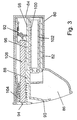
- the manual command unit (22 in Fig. 1), also referred to as a palette unit, has a housing 80 for attachment in the vehicle dashboard, for example.
- Housing 80 defines a generally cylindrical guide cavity 82 with a closed bottom 84 and an outwardly widening handle cavity 86 connected to the end of guide cavity opposite bottom 84.
- a rack structure 96 is fixedly mounted within guide cavity 82 to be coextensive with an axial stroke of ratchet 92.
- Rack structure 96 co-operates with ratchet 92.
- Rack structure 96 is carried by a hollow cylindrical guide member 98 accommodating a piston 100 and a helical pressure spring 102. Piston 100 is connected to handle assembly 88 for joint axial movement against the action of pressure spring 102.
- Release button 94 is axially movably mounted in handle assembly 88 and biased to a normal non-actuated position by a pressure spring 104.
- An actuating rod 106 is connected to release button and has a free end opposite ratchet 92. By depressing release button 94, ratchet 92 is disengaged from rack structure 96.
- the electronic control unit within actuator 10 includes a microprocessor 120 with conventional supply and input terminals, a CAN bus interface 122 for connection to a CAN bus installed in the vehicle, an interface 124 for a number of analog inputs and an interface 126 for connection to the 24, i.e. to manual command unit 22.
- Outputs of microprocessor 120 are connected to inputs of a driver circuit 128 the outputs of which, in turn, are connected to the control gates of power semiconductors 130a to 130d each of which is associated with one of the four windings 132a to 132d of stator 42 (Fig. 2).
- Semiconductors 130a and 130b have their drains interconnected, and a current measurement resistor R1 is connected between both drains and ground.
- semiconductors 130c and 130d have their drains interconnected, and a current measurement resistor R2 is connected between both drains and ground. Current measurement inputs are detected across resistors R1 and R2 and fed to microprocessor 120 through an A/D interface 134.
- the transducer associated with the manual command unit shown in Fig. 3 includes a printed circuit board 140 attached to handle assembly 88 for joint axial movement.
- a plurality of Hall detectors 142a to 142e are mounted on printed circuit board 140 in an axially extending row and spaced from each other.
- a magnetic strip 146 is attached to housing 80 of the manual command unit in a position aligned with the row of Hall detectors 142a to 142e. These Hall detectors with magnetic strip 146 form a position encoder for detecting the position of handle assembly 88 relative to housing 80.
- a row of LEDs 150 is also mounted on printed circuit board 140.
- the actuating rod 106 is made of transparent plastics and constitutes a light guide. When the LEDs 150 are activated, light is coupled into actuating rod 106 for illumination of release button 94.
- a further Hall detector 152 mounted on printed circuit board 140 co-operates with a magnet 154 carried by a pivotal lever 156 coupled with ratchet 92.
- the Hall detector 152 and magnet 154 function as a switch, an "auto-brake” switch, as will be explained below.
- Figs. 1 to 5 of the drawings the park brake system is shown in an non-activated condition.
- spindle 54 with actuating shaft 66 and cable bracket 68 are extended to a first end position so that brake cables 18 20 are not tensioned.
- No electric current is fed to the windings 132a to 132d of the electric motor.
- Spindle 54 is blocked in the fully extended position due to the self-locking feature of the particular thread design of thread 62.
- the handle assembly 88 is in a home position and magnetic strip 146 (Fig. 5) covers only one of the Hall detectors, i.e. Hall detector 142e.
- handle 90 is pulled against the action of spring 102, and handle assembly 88 is moved partially out of housing 80.
- Ratchet 92 engages behind one of the teeth of rack 96, making a clicking noise.
- Magnetic strip 146 now covers Hall detector 142d and uncovers Hall detector 142e, and a corresponding position detection signal is sent on line 24 to the electronic control unit shown in Fig. 4.
- Interface 126 converts these position signals into brake control commands supplied to an input of microprocessor 120.
- microprocessor 120 In response, microprocessor 120 generates appropriate control signals for driver circuit 128, which then drives power semiconductors 130a to 130d to feed electric current to stator windings 132a to 132d of the electric motor.
- the amount of electric current is sensed by resistors R1 and R2, reflecting the torque developed by the electric motor.
- Rotation of gear wheel 52 is converted by the two-step reduction gear into axial movement of spindle 54, thereby moving cable bracket 68 and causing brake cables 18, 20 to be tensioned.
- the degree of park brake actuation will depend on the position of handle assembly 88 relative to housing 80 of the manual command unit 22 within a predetermined range between the home position shown in Fig. 3 and an end position where the handle 90 and release button 94 will project some 20 or 30 mm from the dashboard.
- magnetic strip 146 covers all of the Hall detectors 142a to 142d, only Hall detector 142e remaining uncovered.
- release button 94 is pushed and the free end of actuating rod 106 urges ratchet 92 to disengage from the teeth of rack 92, thereby permitting the handle assembly 88 to return to its home position under the action of spring 102.
- This will cause Hall detector 142e to be covered by magnetic strip 146, and all other Hall detectors will be uncovered.
- a corresponding position signal will be generated and sent to interface 122, thereby causing the microprocessor 120 to generate appropriate brake control signals to move cable bracket 68 to the initial position.
- actuation rod 106 causes lever 156 to pivot and magnet 154 to cover Hall detector 152, thereby generating an "auto-brake" signal supplied to the electronic control unit.
- the LEDs 150 are activated to signal the auto-brake mode by illumination of release button 94.
- the electronic control unit will now automatically activate the park brake whenever a complete stop of the vehicle is detected, and deactivate the park brake as required, e.g. when the accelerator pedal is depressed.
- the release button 94 is depressed again. Alternatively, handle 9 is pulled.
- the auto-brake function may also be disabled whenever the reverse gear is used or when ignition is switched off.
Landscapes
- Engineering & Computer Science (AREA)
- Transportation (AREA)
- Mechanical Engineering (AREA)
- Braking Systems And Boosters (AREA)
- Regulating Braking Force (AREA)
- Braking Elements And Transmission Devices (AREA)
- Braking Arrangements (AREA)
Abstract
Description
Claims (17)
- A park brake system for vehicles comprising:said transducer providing position indicating signals that are converted by said interface into digital control signals enabling the electronic control unit to generate corresponding brake control commands.an actuator with an electric drive motor and an electronic control unit having an interface,a reduction gear having an input connected to the output of the electric motor and an output member for connection to mechanical brakes of the vehicle, anda command unit with a transducer connected to the interface of said electronic control unit;
- The park brake system of claim 1, wherein said reduction gear comprises a fist reduction train and a second reduction train, the first reduction train including a toothed belt connecting an output gear of said drive motor with an intermediate gear and the second reduction train including a threaded spindle and a screw nut engaged with said spindle, said second reduction train being functionally arranged between said intermediate gear and said output member.
- The park brake system of claim 2, wherein said second reduction train is self-locking.
- The park brake system of claim 2, wherein said screw nut forms a hub portion of said intermediate gear and said spindle is axially movably mounted and has a free end provided with said output member.
- The park brake system of claim 4, wherein said output member is adapted for connection to a brake cable.
- The park brake system of claim 1, wherein said electric drive motor is a high torque brushless DC motor.
- The park brake system of claim 2, comprising a common carrier with a base wall mounting said drive motor and said spindle.
- The park brake system of claim 7, wherein said base wall is integrally molded with a tubular mounting structure for said spindle and for said screw nut.
- The park brake system of claim 7, wherein said base wall is integrally molded with a tubular mounting structure for the rotor of said electric drive motor.
- The park brake system of claim 2, wherein said drive motor and reduction gear are mounted on opposite sides of said base wall.
- The park brake system of claim 1, wherein said command unit comprises a manual actuating member movable within a predefined actuating range extending between a home position and an end position, any actuating stroke of said manual actuating member within said range being converted by said transducer into control signals adapted to move said output member across a corresponding stroke within a predefined range of brake strokes.
- The park brake system of claim 11, wherein the transducer comprises a plurality of Hall detectors spaced from each other in a direction corresponding to said actuating range and a magnetic strip, said plurality of Hall detectors and said magnetic strip being movable relative to each other on movement of said manual actuating member to incrementally expose said Hall detectors to said magnetic strip.
- The park brake system of claim 11, wherein said command unit has a ratchet mechanism with a predetermined number of latching positions along said actuating range for selectively latching said actuating member in one of said latching positions, and further has a spring biasing said actuation member to said home position.
- The park brake system of claim 13, wherein said command unit comprises a release button adapted to act on said ratchet mechanism to unlatch said actuating member.
- The park brake system of claim 14, wherein said command unit has an auto-brake control switch which, on actuation, provides a brake activation command whenever the vehicle comes to a complete stop.
- The park brake system of claim 15, wherein said release button functions to actuate said auto-brake control switch if said actuating member is in the home position.
- The park brake system of claim 16, wherein said release button is equipped with visual indication means signalling activation of the auto-brake switch.
Priority Applications (1)
| Application Number | Priority Date | Filing Date | Title |
|---|---|---|---|
| DE2001130537 DE1219518T1 (en) | 2000-12-29 | 2001-12-21 | Parking brake system for motor vehicles |
Applications Claiming Priority (2)
| Application Number | Priority Date | Filing Date | Title |
|---|---|---|---|
| DE20022050 | 2000-12-29 | ||
| DE20022050U | 2000-12-29 |
Publications (3)
| Publication Number | Publication Date |
|---|---|
| EP1219518A2 true EP1219518A2 (en) | 2002-07-03 |
| EP1219518A3 EP1219518A3 (en) | 2002-08-21 |
| EP1219518B1 EP1219518B1 (en) | 2007-10-24 |
Family
ID=7950674
Family Applications (1)
| Application Number | Title | Priority Date | Filing Date |
|---|---|---|---|
| EP01130537A Expired - Lifetime EP1219518B1 (en) | 2000-12-29 | 2001-12-21 | A park brake system for vehicles |
Country Status (4)
| Country | Link |
|---|---|
| US (1) | US6513632B2 (en) |
| EP (1) | EP1219518B1 (en) |
| JP (1) | JP2002255017A (en) |
| DE (1) | DE60131064T2 (en) |
Cited By (6)
| Publication number | Priority date | Publication date | Assignee | Title |
|---|---|---|---|---|
| FR2894213A1 (en) * | 2005-12-02 | 2007-06-08 | Peugeot Citroen Automobiles Sa | Electric hand brake for motor vehicle, has control arm connected to actuator through device converting linear movement of input cable into jerk type non-linear movement of output cable connected to force return spring |
| DE102007047547A1 (en) * | 2007-09-28 | 2009-04-02 | Volkswagen Ag | Brake pedal actuating force detecting device for vehicle, has permanent magnet arranged opposite to Hall sensor and causing relative movement of force receiving unit with respect to force transmission unit for changing Hall voltage |
| WO2009074323A3 (en) * | 2007-12-12 | 2009-07-30 | Lucas Automotive Gmbh | Safety concept for an intelligent actuator |
| FR2941760A1 (en) * | 2009-02-04 | 2010-08-06 | Commissariat Energie Atomique | Cable cylinder, has cable extended into socketed screw and integrated to socketed screw, so that translation of socketed screw causes displacement of cable, and belt extended at level that is same as level of bearing |
| CN103573876A (en) * | 2012-07-27 | 2014-02-12 | 曙制动器工业株式会社 | Drum brake type electric parking brake apparatus |
| CN104417510A (en) * | 2013-09-02 | 2015-03-18 | 通用汽车环球科技运作有限责任公司 | Hand brake device for a vehicle |
Families Citing this family (37)
| Publication number | Priority date | Publication date | Assignee | Title |
|---|---|---|---|---|
| US5983745A (en) * | 1997-04-28 | 1999-11-16 | Petrak; Gregory H. | Park brake cable system including connector clip and associated method of tensioning |
| JP3894733B2 (en) * | 2001-02-15 | 2007-03-22 | 本田技研工業株式会社 | Electric parking brake device |
| EP1231119B1 (en) * | 2001-02-09 | 2005-05-04 | TRW Automotive Electronics & Components GmbH & Co. KG | A park brake system for vehicles |
| WO2003024756A2 (en) * | 2001-09-21 | 2003-03-27 | Petrak Gregory H | Method and apparatus for tensioning an emergency brake system on a vehicle |
| US7331255B2 (en) * | 2001-09-21 | 2008-02-19 | Petrak Gregory H | Method and apparatus for tensioning an emergency brake system on a vehicle |
| US6655506B2 (en) * | 2001-12-26 | 2003-12-02 | Delphi Technologies, Inc. | Electromechanical parking brake |
| AU2003249581A1 (en) * | 2002-07-11 | 2004-02-02 | Brakes India Limited | High performance drum brake assembly for automotive braking system |
| JP2004125163A (en) * | 2002-08-08 | 2004-04-22 | Advics:Kk | Electric brake device |
| JP2004068977A (en) * | 2002-08-08 | 2004-03-04 | Advics:Kk | Wedge-operated disc brake device |
| US7011188B2 (en) * | 2002-08-28 | 2006-03-14 | Ventra Group Inc. | Cable tension sensing device |
| DE102004012355A1 (en) * | 2003-03-18 | 2004-09-30 | Continental Teves Ag & Co. Ohg | Actuator unit for electromechanically operated disk brake has regulator unit arranged at least partly between electric motor and housing accommodating second reduction gear mechanism |
| DE10361127C5 (en) | 2003-12-22 | 2013-10-24 | Brose Fahrzeugteile GmbH & Co. Kommanditgesellschaft, Würzburg | Control device, in particular motor vehicle parking brake |
| IL161323A0 (en) * | 2004-04-08 | 2004-09-27 | Mag Eh Ltd | Electromechanical parking brake |
| FR2878215B1 (en) * | 2004-11-25 | 2007-01-05 | Renault Sas | ELECTRIC BRAKE DEVICE FOR VEHICLE |
| JP4379321B2 (en) * | 2004-12-07 | 2009-12-09 | 株式会社アドヴィックス | Electric brake device for vehicle |
| DE102005001234A1 (en) * | 2005-01-11 | 2006-07-20 | Wabco Gmbh & Co.Ohg | Brake cylinder with parking brake function |
| JP4685491B2 (en) * | 2005-03-31 | 2011-05-18 | 日立オートモティブシステムズ株式会社 | Pedal device |
| DE102005018003A1 (en) * | 2005-04-18 | 2006-10-19 | Siemens Ag | Electric drive of a parking brake |
| DE102005034868B3 (en) * | 2005-07-26 | 2006-08-10 | Knorr-Bremse Systeme für Nutzfahrzeuge GmbH | Disc brake for commercial motor vehicle, has brake lining pressed on over rotatable adjusting spindle, such that thrust piece is pressed at brake disc, and skewable bellow provided for sealing outlet region of spindle from brake caliper |
| DE112006002895B4 (en) * | 2005-10-31 | 2021-12-16 | ZF Active Safety US lnc. | Electrical actuator for a vehicle brake assembly |
| DE102006011928B4 (en) * | 2006-03-14 | 2009-02-26 | Oechsler Ag | Electromotive actuator for a parking brake |
| WO2009018497A1 (en) * | 2007-07-31 | 2009-02-05 | Petrak Gregory H | System and method for tensioning an emergency brake system |
| KR101179103B1 (en) * | 2008-02-20 | 2012-09-07 | 주식회사 만도 | Electric parking brake |
| JP4593649B2 (en) * | 2008-05-23 | 2010-12-08 | 株式会社ホンダアクセス | Vehicle lighting device |
| US8528705B2 (en) * | 2009-10-05 | 2013-09-10 | Ventra Group, Inc. | Brake actuator with improved efficiency |
| DE102010009166B4 (en) * | 2010-02-24 | 2016-07-28 | Honigmann Industrielle Elektronik Gmbh | hysteresis |
| WO2013163458A2 (en) | 2012-04-25 | 2013-10-31 | Innovative System Solutions, Inc | Apparatus, system and method for tensioning an emergency brake system |
| US20150275991A1 (en) * | 2012-10-01 | 2015-10-01 | Deconcepts Pty Ltd | Brake actuation device |
| KR20150069065A (en) * | 2013-12-12 | 2015-06-23 | 주식회사 만도 | electronic parking brake system and control method thereof |
| JP6443354B2 (en) * | 2016-01-22 | 2018-12-26 | 株式会社アドヴィックス | Electric braking device for vehicle |
| US9744950B1 (en) | 2016-08-09 | 2017-08-29 | Ford Global Technologies | Performance electric parking brake controllers |
| US9975529B2 (en) | 2016-08-09 | 2018-05-22 | Ford Global Technologies, Llc | Performance electric parking brake controllers |
| US11002326B2 (en) | 2016-08-31 | 2021-05-11 | Mando Corporation | Electronic parking brake |
| KR102671888B1 (en) * | 2016-08-31 | 2024-06-03 | 에이치엘만도 주식회사 | Electronic parking brake |
| JP6761842B2 (en) * | 2018-10-26 | 2020-09-30 | 株式会社ハイレックスコーポレーション | Load load device |
| FR3118015B1 (en) * | 2020-12-17 | 2023-03-31 | Thales Sa | Winch equipped with a variable torque limiter |
| IT202400000681A1 (en) * | 2024-01-16 | 2025-07-16 | Finan Co S R L | PARKING BRAKE CONTROL SYSTEM OF A MOTOR VEHICLE |
Family Cites Families (17)
| Publication number | Priority date | Publication date | Assignee | Title |
|---|---|---|---|---|
| IT1232034B (en) * | 1989-03-09 | 1992-01-23 | Rgb Spa | ELECTROMECHANICAL LINEAR ACTUATOR |
| DE3924327A1 (en) * | 1989-04-29 | 1990-10-31 | Teves Gmbh Alfred | TRAVEL SENSOR FOR MEASURING MECHANICAL MOTION SIZES |
| ES2084186T3 (en) * | 1990-10-09 | 1996-05-01 | Stridsberg Licensing Ab | AN ELECTRIC POWER TRAIN FOR VEHICLES. |
| US5180038A (en) * | 1992-01-24 | 1993-01-19 | Orscheln Co. | Electronically controlled parking brake system |
| FR2726525B1 (en) * | 1994-11-03 | 1997-01-17 | Rockwell Body & Chassis Syst | ELECTRIC MOTOR VEHICLE PARKING BRAKE |
| DE19627117A1 (en) * | 1995-08-30 | 1997-03-06 | Rohnstock Hans Juergen | Device for measured dispensing of silicon mass or adhesive |
| DE19718679A1 (en) * | 1997-05-02 | 1998-11-05 | Itt Mfg Enterprises Inc | Control system for vehicle parking brake |
| KR100567637B1 (en) * | 1997-11-22 | 2006-04-05 | 콘티넨탈 테베스 아게 운트 코. 오하게 | Method and system of operation of mechanical and electric parking brake for automobile |
| DE19755933C1 (en) * | 1997-12-17 | 1999-08-12 | Kuester & Co Gmbh | Parking brake for vehicles |
| US6213259B1 (en) * | 1998-02-25 | 2001-04-10 | Dura Automotive Systems, Inc. | Device, method and system for control of an electrically powered parking brake |
| FR2782048B1 (en) * | 1998-08-04 | 2000-09-08 | Peugeot | HAND CONTROL DEVICE OF AN ELECTRIC ACTUATOR FOR ACTIVATION OF A SECONDARY BRAKE OF A MOTOR VEHICLE |
| FR2793203B1 (en) * | 1999-05-07 | 2001-06-01 | Renault | ELECTRIC HAND BRAKE CONTROL METHOD AND DEVICE |
| DE10025731B4 (en) * | 1999-05-29 | 2016-02-11 | Continental Teves Ag & Co. Ohg | Service brake system with integrated electric parking brake system |
| US6802401B1 (en) * | 1999-06-01 | 2004-10-12 | Continental Teves Ag & Co., Ohg | Device and method for controlling an electrically actuated parking brake |
| DE19955301B4 (en) * | 1999-11-17 | 2007-11-15 | Bicc Holdings Gmbh | Switch Remote Drive |
| DE19962556A1 (en) * | 1999-12-23 | 2001-07-19 | Daimler Chrysler Ag | Arrangement for actuating vehicle electrical parking brake has redundant electrical switching devices decoupled in direction of motion for detecting parking brake applied, released |
| FR2808486B1 (en) * | 2000-05-03 | 2002-08-30 | Coutier Moulage Gen Ind | ELECTROMECHANICAL DEVICE FOR CONTROLLING A SPARE BRAKE ACTUATOR AND PARKING A MOTOR VEHICLE |
-
2001
- 2001-12-21 EP EP01130537A patent/EP1219518B1/en not_active Expired - Lifetime
- 2001-12-21 DE DE60131064T patent/DE60131064T2/en not_active Expired - Lifetime
- 2001-12-27 JP JP2001396259A patent/JP2002255017A/en active Pending
- 2001-12-27 US US10/034,147 patent/US6513632B2/en not_active Expired - Lifetime
Cited By (9)
| Publication number | Priority date | Publication date | Assignee | Title |
|---|---|---|---|---|
| FR2894213A1 (en) * | 2005-12-02 | 2007-06-08 | Peugeot Citroen Automobiles Sa | Electric hand brake for motor vehicle, has control arm connected to actuator through device converting linear movement of input cable into jerk type non-linear movement of output cable connected to force return spring |
| DE102007047547A1 (en) * | 2007-09-28 | 2009-04-02 | Volkswagen Ag | Brake pedal actuating force detecting device for vehicle, has permanent magnet arranged opposite to Hall sensor and causing relative movement of force receiving unit with respect to force transmission unit for changing Hall voltage |
| DE102007047547B4 (en) * | 2007-09-28 | 2018-02-08 | Volkswagen Ag | Device and method for detecting an operating force of a brake pedal |
| WO2009074323A3 (en) * | 2007-12-12 | 2009-07-30 | Lucas Automotive Gmbh | Safety concept for an intelligent actuator |
| US8423241B2 (en) | 2007-12-12 | 2013-04-16 | Lucas Automotive Gmbh | Safety concept for an intelligent actuator |
| FR2941760A1 (en) * | 2009-02-04 | 2010-08-06 | Commissariat Energie Atomique | Cable cylinder, has cable extended into socketed screw and integrated to socketed screw, so that translation of socketed screw causes displacement of cable, and belt extended at level that is same as level of bearing |
| CN103573876A (en) * | 2012-07-27 | 2014-02-12 | 曙制动器工业株式会社 | Drum brake type electric parking brake apparatus |
| CN103573876B (en) * | 2012-07-27 | 2016-10-05 | 曙制动器工业株式会社 | Drum brake type electric parking brake device |
| CN104417510A (en) * | 2013-09-02 | 2015-03-18 | 通用汽车环球科技运作有限责任公司 | Hand brake device for a vehicle |
Also Published As
| Publication number | Publication date |
|---|---|
| DE60131064D1 (en) | 2007-12-06 |
| EP1219518B1 (en) | 2007-10-24 |
| EP1219518A3 (en) | 2002-08-21 |
| US6513632B2 (en) | 2003-02-04 |
| DE60131064T2 (en) | 2008-08-14 |
| US20020084154A1 (en) | 2002-07-04 |
| JP2002255017A (en) | 2002-09-11 |
Similar Documents
| Publication | Publication Date | Title |
|---|---|---|
| EP1219518B1 (en) | A park brake system for vehicles | |
| JP3132117U (en) | Parking brake device for vehicle | |
| US6386338B1 (en) | Electric parking brake manual override | |
| EP1767419B1 (en) | Electrically driven cable drive device and electric brake device | |
| US4843901A (en) | Electric shift apparatus with manual override | |
| CN100422006C (en) | Actuating mechanism of automobile parking brake | |
| US6736233B2 (en) | Electro-mechanical actuator for an adjustable pedal system | |
| US7448475B2 (en) | Device for controlling a motor-vehicle servo-assisted brake | |
| US20110112741A1 (en) | Electric parking brake for vehicle | |
| KR101454925B1 (en) | Electronic Parking Brake Device Using Load Sensing Limit Switch | |
| CN114787006A (en) | Brake pressure generator capable of electromechanical driving | |
| KR101391103B1 (en) | Motor axial connecting typed electrical parking brake in vehicle | |
| US5969495A (en) | Accelerator device for electromotive vehicles | |
| JPH04505736A (en) | automotive control system | |
| JP4832976B2 (en) | Electric cable drive device and electric parking brake | |
| JP4928089B2 (en) | Electric cable drive device and electric brake device | |
| US6647814B2 (en) | Selective drive mechanism | |
| JP4867292B2 (en) | Tension sensor and electric parking brake | |
| KR100928220B1 (en) | Electronic parking brake system | |
| JP4867278B2 (en) | Tension sensor and electric parking brake | |
| KR100452289B1 (en) | Parking brake apparatus actuated by a motor | |
| KR20110057761A (en) | Electronic parking brake | |
| JP2009012576A (en) | Electric parking brake device | |
| HK1083087A (en) | Device for controlling a motor-vehicle servo-assisted brake | |
| HUP0203862A2 (en) | Controller of arrester brake |
Legal Events
| Date | Code | Title | Description |
|---|---|---|---|
| PUAI | Public reference made under article 153(3) epc to a published international application that has entered the european phase |
Free format text: ORIGINAL CODE: 0009012 |
|
| AK | Designated contracting states |
Kind code of ref document: A2 Designated state(s): AT BE CH CY DE DK ES FI FR GB GR IE IT LI LU MC NL PT SE TR |
|
| AX | Request for extension of the european patent |
Free format text: AL;LT;LV;MK;RO;SI |
|
| PUAL | Search report despatched |
Free format text: ORIGINAL CODE: 0009013 |
|
| AK | Designated contracting states |
Kind code of ref document: A3 Designated state(s): AT BE CH CY DE DK ES FI FR GB GR IE IT LI LU MC NL PT SE TR |
|
| AX | Request for extension of the european patent |
Free format text: AL;LT;LV;MK;RO;SI |
|
| EL | Fr: translation of claims filed | ||
| DET | De: translation of patent claims | ||
| 17P | Request for examination filed |
Effective date: 20030203 |
|
| AKX | Designation fees paid |
Designated state(s): DE FR GB IT |
|
| GRAP | Despatch of communication of intention to grant a patent |
Free format text: ORIGINAL CODE: EPIDOSNIGR1 |
|
| GRAS | Grant fee paid |
Free format text: ORIGINAL CODE: EPIDOSNIGR3 |
|
| GRAA | (expected) grant |
Free format text: ORIGINAL CODE: 0009210 |
|
| AK | Designated contracting states |
Kind code of ref document: B1 Designated state(s): DE FR GB IT |
|
| REG | Reference to a national code |
Ref country code: GB Ref legal event code: FG4D Free format text: NOT ENGLISH |
|
| REF | Corresponds to: |
Ref document number: 60131064 Country of ref document: DE Date of ref document: 20071206 Kind code of ref document: P |
|
| RAP2 | Party data changed (patent owner data changed or rights of a patent transferred) |
Owner name: TRW AUTOMOTIVE ELECTRONICS & COMPONENTS GMBH |
|
| ET | Fr: translation filed | ||
| PLBE | No opposition filed within time limit |
Free format text: ORIGINAL CODE: 0009261 |
|
| STAA | Information on the status of an ep patent application or granted ep patent |
Free format text: STATUS: NO OPPOSITION FILED WITHIN TIME LIMIT |
|
| 26N | No opposition filed |
Effective date: 20080725 |
|
| PGFP | Annual fee paid to national office [announced via postgrant information from national office to epo] |
Ref country code: FR Payment date: 20091221 Year of fee payment: 9 Ref country code: GB Payment date: 20091216 Year of fee payment: 9 Ref country code: IT Payment date: 20091218 Year of fee payment: 9 |
|
| GBPC | Gb: european patent ceased through non-payment of renewal fee |
Effective date: 20101221 |
|
| REG | Reference to a national code |
Ref country code: FR Ref legal event code: ST Effective date: 20110831 |
|
| PG25 | Lapsed in a contracting state [announced via postgrant information from national office to epo] |
Ref country code: FR Free format text: LAPSE BECAUSE OF NON-PAYMENT OF DUE FEES Effective date: 20110103 |
|
| PG25 | Lapsed in a contracting state [announced via postgrant information from national office to epo] |
Ref country code: GB Free format text: LAPSE BECAUSE OF NON-PAYMENT OF DUE FEES Effective date: 20101221 |
|
| PG25 | Lapsed in a contracting state [announced via postgrant information from national office to epo] |
Ref country code: IT Free format text: LAPSE BECAUSE OF NON-PAYMENT OF DUE FEES Effective date: 20101221 |
|
| PGFP | Annual fee paid to national office [announced via postgrant information from national office to epo] |
Ref country code: DE Payment date: 20141230 Year of fee payment: 14 |
|
| REG | Reference to a national code |
Ref country code: DE Ref legal event code: R119 Ref document number: 60131064 Country of ref document: DE |
|
| PG25 | Lapsed in a contracting state [announced via postgrant information from national office to epo] |
Ref country code: DE Free format text: LAPSE BECAUSE OF NON-PAYMENT OF DUE FEES Effective date: 20160701 |