EP1219473A2 - Plug-in tow device - Google Patents
Plug-in tow device Download PDFInfo
- Publication number
- EP1219473A2 EP1219473A2 EP01310333A EP01310333A EP1219473A2 EP 1219473 A2 EP1219473 A2 EP 1219473A2 EP 01310333 A EP01310333 A EP 01310333A EP 01310333 A EP01310333 A EP 01310333A EP 1219473 A2 EP1219473 A2 EP 1219473A2
- Authority
- EP
- European Patent Office
- Prior art keywords
- shaft
- towing device
- inches
- bracket
- notch
- Prior art date
- Legal status (The legal status is an assumption and is not a legal conclusion. Google has not performed a legal analysis and makes no representation as to the accuracy of the status listed.)
- Granted
Links
Images


Classifications
-
- B—PERFORMING OPERATIONS; TRANSPORTING
- B60—VEHICLES IN GENERAL
- B60D—VEHICLE CONNECTIONS
- B60D1/00—Traction couplings; Hitches; Draw-gear; Towing devices
- B60D1/48—Traction couplings; Hitches; Draw-gear; Towing devices characterised by the mounting
- B60D1/488—Traction couplings; Hitches; Draw-gear; Towing devices characterised by the mounting mounted directly to the chassis of the towing vehicle
-
- B—PERFORMING OPERATIONS; TRANSPORTING
- B60—VEHICLES IN GENERAL
- B60D—VEHICLE CONNECTIONS
- B60D1/00—Traction couplings; Hitches; Draw-gear; Towing devices
- B60D1/48—Traction couplings; Hitches; Draw-gear; Towing devices characterised by the mounting
- B60D1/52—Traction couplings; Hitches; Draw-gear; Towing devices characterised by the mounting removably mounted
-
- B—PERFORMING OPERATIONS; TRANSPORTING
- B60—VEHICLES IN GENERAL
- B60D—VEHICLE CONNECTIONS
- B60D1/00—Traction couplings; Hitches; Draw-gear; Towing devices
- B60D1/48—Traction couplings; Hitches; Draw-gear; Towing devices characterised by the mounting
- B60D1/56—Traction couplings; Hitches; Draw-gear; Towing devices characterised by the mounting securing to the vehicle bumper
- B60D1/565—Traction couplings; Hitches; Draw-gear; Towing devices characterised by the mounting securing to the vehicle bumper having an eyelet
Definitions
- the present invention relates to land vehicles and vehicle mounting or clamps, and more particularly, to a towing device having one portion detachably attached to the vehicle and another portion engageable with the first portion,
- Optimally, such a design would be attached directly to a forward location along the vehicle's main frame, so as to put minimal stress on associated brackets in transferring loads from the tow hitch to the frame.
- the ideal hitch should be located as close to the center of the front of the vehicle as possible, to align the vehicle with whatever machinery is towing it. The present invention is directed to fulfilling these needs and others as described below.
- a towing device including a bracket and an elongate hitch rod.
- the bracket includes a longitudinal bore and one or more pins oriented transverse to the longitudinal bore. An end portion of each pin extends partially into the longitudinal bore.
- the hitch rod includes a cylindrical shaft and a clevis connected to the shaft's distal end. The clevis is attached to the shaft in a manner that weights the shaft in a desired orientation.
- the shaft includes at least one groove with a spiral portion and a notch. The spiral portion extends from the shaft's proximal end and ends with the notch.
- the transverse pin engages the notch, thereby locking the rod with the bracket.
- the weighted orientation of the shaft encourages this engaged arrangement.
- a bracket in accordance with other aspects of the invention, includes a longitudinal bore with a transverse protrusion extending partially into the longitudinal bore.
- a hitch rod is provided and formed as a cylindrical shaft with a groove located therealong.
- the groove includes a spiral portion and a notch, with the spiral portion extending from the shaft's proximal end and ending with the notch.
- the hitch rod includes a desired orientation, the hitch rod being weighted to move to the desired orientation.
- the hitch rod includes a connection member connected to the shaft distal end. The connection member is attached to the shaft in a manner that weights the shaft in a desired orientation.
- the connection member is a clevis.
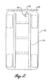
- the present invention is a plug-in tow device 10 having a bracket 12 and a hitch rod 14.
- the bracket 12 is attached to a forward end of one of the vehicle's main rail frames 16.
- the frame 16 is a C-shaped beam, and the bracket 12 is bolted directly to the frame 16.
- FIGURE 2 is a bottom-up schematic plan view of the plug-in tow device 10 showing their relative placement.
- the vehicle includes a body 18 and a forward bumper 20. An opening 22 in the bumper is provided to accommodate the hitch rod, as described below.
- the bracket includes an attachment flange 30 that is shaped to correspond to the shape of frame 16.
- a body portion 32 includes a longitudinal bore 34 and a transverse pin 34.
- the longitudinal bore is cylindrically shaped with a diameter in the range of about 1.5 inches to about 3.0 inches.
- the pin 34 is positioned within the body 32 such that the distal end of the pin extends a small distance transversely into the bore 34, for example by an amount of about 0.2 to about 0.5 inches.
- the pin extends into the bore at a location from the front of the bracket in the range of about 6 inches to about 10 inches.
- the body 32 may further include various flanges and holes to accommodate other components.
- the pin is formed of a material known to those of skill in the art, such as from an aluiminum or iron material.
- the pin is a component that is formed separately from the bracket itself. In this regard, the pin may be threaded to the blacket or pressed into place. Alternatively, the pin may be integrally formed with the bracket, if desired.
- the hitch rod 16 includes a cylindrical shaft 50 and a clevis 52, as shown best in FIGURE 3.
- the elongate hitch rod is a steel rod of a length in the range of about 12 inches to about 20 inches, with the shaft having a length of an amount in the range of about 10 inches to about 18 inches.
- the clevis includes opposed upper and lower arms 56, 58, respectively. Holes 54 extend through each arm and are aligned to one another. Referring particularly to FIGURE 4, the clevis 52 is attached to the shaft 50 such that the center of gravity of the clevis is below the center of gravity for the shaft.
- connection heads could be used in lieu a clevis/pin arrangement.
- a simple ring may be provided.
- the shaft 52 includes one or more grooves 60.
- the plug-in tow device 10 can be located on either left or right side rail frames.
- Each groove includes a spiral portion 62 and a notch portion 64.
- the notch portion 64 is placed so that when the hitch rod is located in an upright orientation (as is shown in FIGURE 4), the notch is positioned along the side of the shaft, approximately mid-height.
- the notch is oriented rearward.
- each groove extends a total longitudinal distance along the shaft by an amount in the range of about 4 inches to about 8 inches.
- hitch rod To connect the hitch rod with an installed bracket, an operator inserts the hitch rod through the bumper opening and into the longitudinal bore 34.
- the hitch rod should be oriented so that the groove will engage the transverse pin within the bore. For the embodiments shown, this means basically orienting the hitch rod upside down when inserting it into the bore.
- the hitch rod follows the connection of the fixed pins within the grooves.
- the opening in the bumper may be made large enough to clear the rod clevis, or alternatively, the hitch rod may be made long enough to extend out the bumper opening.
- the grooves change direction and thereby force the transverse pin into the recessed notch 64. This secures the connection of the rod 14 to the drive bracket 12, particularly as the weight of the vehicle as it's towed will tend to trap the pin into the rearward facing notch. Removal of the hitch is done in reverse order.
- the hitch rod may be installed into the bracket without any tools or separate cross-pin pieces, which could be easily misplaced.
- the hitch rod will always move to its weighted orientation, thus ensuring that it remaining within the notch 64.
- the bracket may be equipped with two transverse pins, located opposite one another, and two grooves.
- each groove would engage a pin, thereby providing a redundant rod-bracket connection.
Landscapes
- Engineering & Computer Science (AREA)
- Transportation (AREA)
- Mechanical Engineering (AREA)
- Agricultural Machines (AREA)
- Electric Cable Installation (AREA)
- Body Structure For Vehicles (AREA)
- Snaps, Bayonet Connections, Set Pins, And Snap Rings (AREA)
Abstract
Description
Claims (17)
- A towing device comprising:wherein during use, the at least one transverse pin engages the notch and the weighted orientation of the shaft encourages the engaged arrangement.(a) a bracket connectable to a vehicle, the bracket having a longitudinal bore and at least one pin oriented transverse to the longitudinal bore, an end portion of the pin extending partially into the longitudinal bore;(b) an elongate hitch rod including a cylindrical shaft with a distal end and a proximal end and a clevis connected to the shaft distal end; the clevis being attached to the shaft in a manner that weights the shaft in a desired orientation; the shaft including at least one groove with a spiral portion and a notch; the spiral portion extending from the shaft proximal end and ending with the notch;
- The towing device of Claim 1, wherein the bracket includes an attachment flange adapted to connect to a vehicle main frame rail.
- The towing device of Claim 1, wherein the at least one pin extends into the bore by an amount in the range of about 0.2 inches to about 0.5 inches.
- The towing device of Claim 1, wherein the at least one pin is located approximately mid-way along the longitudinal bore.
- The towing device of Claim 1, wherein the at least one pin is separable from the bracket and it connected thereto by being threaded or pressed into the bracket.
- The towing device of Claim 1, wherein the bracket includes a single pin oriented transverse to the longitudinal bore.
- The towing device of Claim 6, wherein the longitudinal bore is cylindrically shaped with a diameter in the range of about 1.5 inches to about 3.0 inches; the pin extending into the bore at a location in the range of about 6 inches to about 10 inches from the front of the bracket.
- The towing device of Claim 1, wherein the elongate hitch rod is of a length in the range of about 12 inches to about 20 inches.
- The towing device of Claim 1, wherein the elongate hitch rod is formed from steel.
- The towing device of Claim 1, wherein the clevis includes an upper ann and a lower arm; the upper arm being located closer to the shaft than the lower arm.
- The towing device of Claim 1, wherein the shaft includes a single groove with a spiral portion and a notch.
- The towing device of Claim 1, wherein the shaft is of a length in the range of about 10 inches to about 18 inches; and wherein the at least one groove extends a total longitudinal distance along the shaft by an amount in the range of about 4 inches to about 8 inches.
- The towing device of Claim 1, wherein the spiral is located about the shaft in a clockwise direction.
- A towing device comprising:wherein during use, an operator inserts the proximal end of the shaft into the longitudinal bore, engaging the at least one groove with the at least one transverse protrusion; while continuing to insert the shaft into the bore, the operator moves the shaft so that each protrusion follows its respective groove until engaging the notch.(a) a bracket connectable to a vehicle, the bracket having a longitudinal bore and at least one transverse protrusion extending partially into the longitudinal bore;(b) a hitch rod formed as a cylindrical shaft with a distal end and a proximal end, the shaft including at least one groove with a spiral portion and a notch; the spiral portion extending from the shaft proximal end and ending with the notch;
- The towing device of Claim 14, wherein the connection member is a clevis.
- The towing device of Claim 14, wherein the hitch rod includes a desired orientation, the hitch rod being weighted to move to the desired orientation.
- The towing device of Claim 16, wherein the hitch rod includes a connection member connected to the shaft distal end; the connection member being attached to the shaft in a manner that weights the shaft in the desired orientation.
Applications Claiming Priority (2)
| Application Number | Priority Date | Filing Date | Title |
|---|---|---|---|
| US09/735,102 US6386573B1 (en) | 2000-12-11 | 2000-12-11 | Plug-in tow device |
| US735102 | 2000-12-11 |
Publications (3)
| Publication Number | Publication Date |
|---|---|
| EP1219473A2 true EP1219473A2 (en) | 2002-07-03 |
| EP1219473A3 EP1219473A3 (en) | 2003-01-02 |
| EP1219473B1 EP1219473B1 (en) | 2006-04-19 |
Family
ID=24954370
Family Applications (1)
| Application Number | Title | Priority Date | Filing Date |
|---|---|---|---|
| EP01310333A Expired - Lifetime EP1219473B1 (en) | 2000-12-11 | 2001-12-11 | Plug-in tow device |
Country Status (7)
| Country | Link |
|---|---|
| US (1) | US6386573B1 (en) |
| EP (1) | EP1219473B1 (en) |
| AT (1) | ATE323610T1 (en) |
| AU (1) | AU779782B2 (en) |
| CA (1) | CA2363426C (en) |
| DE (1) | DE60118870T2 (en) |
| MX (1) | MXPA01011678A (en) |
Families Citing this family (18)
| Publication number | Priority date | Publication date | Assignee | Title |
|---|---|---|---|---|
| US6749212B2 (en) * | 2002-02-21 | 2004-06-15 | Trek Bicycle Corporation | Bicycle trailer hitch or accessory mount |
| NL1021479C2 (en) * | 2002-09-17 | 2004-04-06 | Brink Internat B V | Coupling assembly for vehicles. |
| US6837510B1 (en) * | 2002-09-27 | 2005-01-04 | James L. Karls | Pinball hitch |
| KR100521604B1 (en) * | 2003-04-14 | 2005-10-12 | 현대자동차주식회사 | Front shipping hook structure capable of providing multi-face supports and relevant improved structures in an Automobile for fastening the same |
| US20050253445A1 (en) * | 2003-07-18 | 2005-11-17 | Aaron Beiler | Self propelled trailer |
| US20080211289A1 (en) * | 2007-03-01 | 2008-09-04 | Aaron Beiler | Self-Propelled Trailer |
| USD569770S1 (en) | 2007-03-23 | 2008-05-27 | Biery Jr Jack F | Vehicular tow bar for accepting a storable coupler |
| US8047331B2 (en) * | 2008-02-13 | 2011-11-01 | Spicer John W | Ladder attachment for hitch |
| WO2013033237A1 (en) * | 2011-08-29 | 2013-03-07 | Bright Technologies, Llc | Locking pin with spring retention mechanism |
| CN104648064A (en) * | 2014-06-19 | 2015-05-27 | 东风柳州汽车有限公司 | Detachable front towing hook device for heavy lorry |
| WO2016004200A2 (en) | 2014-07-01 | 2016-01-07 | Beiler Aaron Jay | Self-propelled trailer |
| DE102014110829A1 (en) * | 2014-07-30 | 2016-02-04 | Dr. Ing. H.C. F. Porsche Aktiengesellschaft | Abschleppösenanordnung |
| DE102014110830A1 (en) * | 2014-07-30 | 2016-02-04 | Dr. Ing. H.C. F. Porsche Aktiengesellschaft | Device for attaching a tow bar or a tow rope |
| US10017091B2 (en) | 2014-12-11 | 2018-07-10 | New Heights Llc | Self-propelled trailer |
| JP6407778B2 (en) * | 2015-03-26 | 2018-10-17 | 株式会社神戸製鋼所 | Bumper reinforcement and hook bracket mounting structure |
| US10464463B2 (en) | 2016-08-11 | 2019-11-05 | New Heights, Llc | Mobile storage device |
| US20230166571A1 (en) * | 2021-11-30 | 2023-06-01 | Jerry A. Edwards | Adapter assembly for vehicle baseplate and tow bar assembly |
| DE102024104978B4 (en) * | 2024-02-22 | 2026-05-07 | Dr. Ing. H.C. F. Porsche Aktiengesellschaft | Towing eye arrangement for an interchangeable towing eye for a motor vehicle, motor vehicle |
Family Cites Families (19)
| Publication number | Priority date | Publication date | Assignee | Title |
|---|---|---|---|---|
| US2133065A (en) * | 1936-03-28 | 1938-10-11 | Weber Tobias | Coupler |
| US2639160A (en) | 1950-01-23 | 1953-05-19 | Robert H Studebaker | Trailer hitch |
| DE863001C (en) * | 1951-05-08 | 1953-01-15 | Wilhelm Peppmeier | Drawbar for trailer couplings on vehicles |
| US2940776A (en) | 1958-12-22 | 1960-06-14 | Eugene W Curtis | Trailer coupling mechanism |
| US3685864A (en) * | 1971-03-22 | 1972-08-22 | Robert M Hall | Locking pin coupling |
| US3801134A (en) * | 1972-07-26 | 1974-04-02 | D Dees | Multi-hitch element tow hitch construction |
| US4253680A (en) | 1979-03-09 | 1981-03-03 | Albright John M | Hitch facilitating |
| US4298212A (en) * | 1979-11-27 | 1981-11-03 | Jamison Merle A | Hitch pin |
| US4783094A (en) * | 1987-07-20 | 1988-11-08 | Sands John E | Safety device for hitch pins |
| US5149122A (en) * | 1991-04-26 | 1992-09-22 | Helber Robert A | Adjustable hitch assembly |
| US5472222A (en) * | 1994-09-02 | 1995-12-05 | Marcy; Dewey R. | Hitch for goose neck trailer |
| US5536032A (en) * | 1995-02-13 | 1996-07-16 | Allied Products Corporation | Implement and hitch |
| US5685554A (en) * | 1995-10-27 | 1997-11-11 | Poxleitner; Harold C. | Telescoping tow bar apparatus |
| US5860671A (en) | 1996-08-08 | 1999-01-19 | Pro-Hitch Manufacturing, Inc. | Retractable trailer hitch |
| US5853187A (en) | 1996-11-22 | 1998-12-29 | Maier; James P. | Snowmobile hitch |
| DE19651562A1 (en) * | 1996-12-11 | 1998-06-18 | Peter Rocca | Vehicle towbar for towing trailer or caravan |
| US5871222A (en) | 1997-04-22 | 1999-02-16 | Webb; Micheal L. | Detachable ball hitch apparatus and methods |
| US6149181A (en) * | 1998-02-03 | 2000-11-21 | Biederman; Frederick Lee | Self-storing hitch |
| US6099015A (en) * | 1999-10-07 | 2000-08-08 | Quick-Hitch, Inc. | Hitch system for gooseneck trailer |
-
2000
- 2000-12-11 US US09/735,102 patent/US6386573B1/en not_active Expired - Lifetime
-
2001
- 2001-11-15 MX MXPA01011678A patent/MXPA01011678A/en unknown
- 2001-11-20 CA CA002363426A patent/CA2363426C/en not_active Expired - Fee Related
- 2001-12-07 AU AU97142/01A patent/AU779782B2/en not_active Ceased
- 2001-12-11 DE DE60118870T patent/DE60118870T2/en not_active Expired - Lifetime
- 2001-12-11 EP EP01310333A patent/EP1219473B1/en not_active Expired - Lifetime
- 2001-12-11 AT AT01310333T patent/ATE323610T1/en not_active IP Right Cessation
Non-Patent Citations (1)
| Title |
|---|
| None |
Also Published As
| Publication number | Publication date |
|---|---|
| ATE323610T1 (en) | 2006-05-15 |
| CA2363426C (en) | 2008-07-08 |
| CA2363426A1 (en) | 2002-06-11 |
| MXPA01011678A (en) | 2004-11-10 |
| AU779782B2 (en) | 2005-02-10 |
| DE60118870D1 (en) | 2006-05-24 |
| EP1219473A3 (en) | 2003-01-02 |
| EP1219473B1 (en) | 2006-04-19 |
| AU9714201A (en) | 2002-06-13 |
| DE60118870T2 (en) | 2006-12-07 |
| US6386573B1 (en) | 2002-05-14 |
Similar Documents
| Publication | Publication Date | Title |
|---|---|---|
| CA2363426C (en) | Plug-in tow device | |
| US6802523B1 (en) | Safety fastener for ball and socket hitch | |
| US4840392A (en) | Trailer hitch guide | |
| US6536794B2 (en) | Tow hitch assembly for all-terrain vehicles | |
| US5580076A (en) | Automatic trailer hitch system | |
| US5161815A (en) | Self aligning trailer hitch | |
| US6796573B2 (en) | Trailer hitch guide | |
| US6902181B1 (en) | Trailer hitch having rapid adjustment | |
| US4792153A (en) | Trailer hitch | |
| US5516139A (en) | Guide assembly | |
| US4944525A (en) | Self locking trailer hitch | |
| WO2002034569A2 (en) | Accessory mounting system for trailer hitch assembly | |
| US20110210530A1 (en) | Tow hitch | |
| US20020017770A1 (en) | Trailer rack rack | |
| US4863185A (en) | Universal trailer hitch apparatus | |
| US4192524A (en) | Trailer hitch apparatus | |
| US20030080263A1 (en) | Accessory mounting adapter for a trailer hitch assembly | |
| CA2095949A1 (en) | Self Aligning Hitch | |
| US4976453A (en) | Towing hitch with shiftable hitch member | |
| AU749207B2 (en) | Adjustable coupler for a weight distributing trailer hitch apparatus | |
| US7025371B2 (en) | Hitching apparatus and method of use | |
| EP2080644A1 (en) | A swivel hitch | |
| US6866315B2 (en) | Receiver assembly with load bed extender | |
| US20070057485A1 (en) | Trailer hitch guidance system | |
| US20040012170A1 (en) | Accessory mounting adapter for a trailer hitch assembly |
Legal Events
| Date | Code | Title | Description |
|---|---|---|---|
| PUAI | Public reference made under article 153(3) epc to a published international application that has entered the european phase |
Free format text: ORIGINAL CODE: 0009012 |
|
| AK | Designated contracting states |
Kind code of ref document: A2 Designated state(s): AT BE CH CY DE DK ES FI FR GB GR IE IT LI LU MC NL PT SE TR |
|
| AX | Request for extension of the european patent |
Free format text: AL;LT;LV;MK;RO;SI |
|
| PUAL | Search report despatched |
Free format text: ORIGINAL CODE: 0009013 |
|
| AK | Designated contracting states |
Kind code of ref document: A3 Designated state(s): AT BE CH CY DE DK ES FI FR GB GR IE IT LI LU MC NL PT SE TR |
|
| AX | Request for extension of the european patent |
Free format text: AL;LT;LV;MK;RO;SI |
|
| 17P | Request for examination filed |
Effective date: 20030626 |
|
| AKX | Designation fees paid |
Designated state(s): AT BE CH CY DE DK ES FI FR GB GR IE IT LI LU MC NL PT SE TR |
|
| 17Q | First examination report despatched |
Effective date: 20041207 |
|
| GRAP | Despatch of communication of intention to grant a patent |
Free format text: ORIGINAL CODE: EPIDOSNIGR1 |
|
| GRAS | Grant fee paid |
Free format text: ORIGINAL CODE: EPIDOSNIGR3 |
|
| GRAA | (expected) grant |
Free format text: ORIGINAL CODE: 0009210 |
|
| AK | Designated contracting states |
Kind code of ref document: B1 Designated state(s): AT BE CH CY DE DK ES FI FR GB GR IE IT LI LU MC NL PT SE TR |
|
| PG25 | Lapsed in a contracting state [announced via postgrant information from national office to epo] |
Ref country code: IT Free format text: LAPSE BECAUSE OF FAILURE TO SUBMIT A TRANSLATION OF THE DESCRIPTION OR TO PAY THE FEE WITHIN THE PRESCRIBED TIME-LIMIT;WARNING: LAPSES OF ITALIAN PATENTS WITH EFFECTIVE DATE BEFORE 2007 MAY HAVE OCCURRED AT ANY TIME BEFORE 2007. THE CORRECT EFFECTIVE DATE MAY BE DIFFERENT FROM THE ONE RECORDED. Effective date: 20060419 Ref country code: CH Free format text: LAPSE BECAUSE OF FAILURE TO SUBMIT A TRANSLATION OF THE DESCRIPTION OR TO PAY THE FEE WITHIN THE PRESCRIBED TIME-LIMIT Effective date: 20060419 Ref country code: AT Free format text: LAPSE BECAUSE OF FAILURE TO SUBMIT A TRANSLATION OF THE DESCRIPTION OR TO PAY THE FEE WITHIN THE PRESCRIBED TIME-LIMIT Effective date: 20060419 Ref country code: BE Free format text: LAPSE BECAUSE OF FAILURE TO SUBMIT A TRANSLATION OF THE DESCRIPTION OR TO PAY THE FEE WITHIN THE PRESCRIBED TIME-LIMIT Effective date: 20060419 Ref country code: FI Free format text: LAPSE BECAUSE OF FAILURE TO SUBMIT A TRANSLATION OF THE DESCRIPTION OR TO PAY THE FEE WITHIN THE PRESCRIBED TIME-LIMIT Effective date: 20060419 Ref country code: LI Free format text: LAPSE BECAUSE OF FAILURE TO SUBMIT A TRANSLATION OF THE DESCRIPTION OR TO PAY THE FEE WITHIN THE PRESCRIBED TIME-LIMIT Effective date: 20060419 |
|
| REG | Reference to a national code |
Ref country code: GB Ref legal event code: FG4D |
|
| REG | Reference to a national code |
Ref country code: SE Ref legal event code: TRGR |
|
| REF | Corresponds to: |
Ref document number: 60118870 Country of ref document: DE Date of ref document: 20060524 Kind code of ref document: P |
|
| REG | Reference to a national code |
Ref country code: IE Ref legal event code: FG4D |
|
| PG25 | Lapsed in a contracting state [announced via postgrant information from national office to epo] |
Ref country code: DK Free format text: LAPSE BECAUSE OF FAILURE TO SUBMIT A TRANSLATION OF THE DESCRIPTION OR TO PAY THE FEE WITHIN THE PRESCRIBED TIME-LIMIT Effective date: 20060719 |
|
| PG25 | Lapsed in a contracting state [announced via postgrant information from national office to epo] |
Ref country code: ES Free format text: LAPSE BECAUSE OF FAILURE TO SUBMIT A TRANSLATION OF THE DESCRIPTION OR TO PAY THE FEE WITHIN THE PRESCRIBED TIME-LIMIT Effective date: 20060730 |
|
| PG25 | Lapsed in a contracting state [announced via postgrant information from national office to epo] |
Ref country code: PT Free format text: LAPSE BECAUSE OF FAILURE TO SUBMIT A TRANSLATION OF THE DESCRIPTION OR TO PAY THE FEE WITHIN THE PRESCRIBED TIME-LIMIT Effective date: 20060919 |
|
| REG | Reference to a national code |
Ref country code: CH Ref legal event code: PL |
|
| PG25 | Lapsed in a contracting state [announced via postgrant information from national office to epo] |
Ref country code: IE Free format text: LAPSE BECAUSE OF NON-PAYMENT OF DUE FEES Effective date: 20061211 |
|
| PG25 | Lapsed in a contracting state [announced via postgrant information from national office to epo] |
Ref country code: MC Free format text: LAPSE BECAUSE OF NON-PAYMENT OF DUE FEES Effective date: 20061231 |
|
| PLBE | No opposition filed within time limit |
Free format text: ORIGINAL CODE: 0009261 |
|
| STAA | Information on the status of an ep patent application or granted ep patent |
Free format text: STATUS: NO OPPOSITION FILED WITHIN TIME LIMIT |
|
| 26N | No opposition filed |
Effective date: 20070122 |
|
| EN | Fr: translation not filed | ||
| PG25 | Lapsed in a contracting state [announced via postgrant information from national office to epo] |
Ref country code: FR Free format text: LAPSE BECAUSE OF FAILURE TO SUBMIT A TRANSLATION OF THE DESCRIPTION OR TO PAY THE FEE WITHIN THE PRESCRIBED TIME-LIMIT Effective date: 20070309 Ref country code: GR Free format text: LAPSE BECAUSE OF FAILURE TO SUBMIT A TRANSLATION OF THE DESCRIPTION OR TO PAY THE FEE WITHIN THE PRESCRIBED TIME-LIMIT Effective date: 20060720 |
|
| PG25 | Lapsed in a contracting state [announced via postgrant information from national office to epo] |
Ref country code: TR Free format text: LAPSE BECAUSE OF FAILURE TO SUBMIT A TRANSLATION OF THE DESCRIPTION OR TO PAY THE FEE WITHIN THE PRESCRIBED TIME-LIMIT Effective date: 20060419 Ref country code: LU Free format text: LAPSE BECAUSE OF NON-PAYMENT OF DUE FEES Effective date: 20061211 |
|
| PG25 | Lapsed in a contracting state [announced via postgrant information from national office to epo] |
Ref country code: FR Free format text: LAPSE BECAUSE OF FAILURE TO SUBMIT A TRANSLATION OF THE DESCRIPTION OR TO PAY THE FEE WITHIN THE PRESCRIBED TIME-LIMIT Effective date: 20060419 Ref country code: CY Free format text: LAPSE BECAUSE OF FAILURE TO SUBMIT A TRANSLATION OF THE DESCRIPTION OR TO PAY THE FEE WITHIN THE PRESCRIBED TIME-LIMIT Effective date: 20060419 |
|
| PGFP | Annual fee paid to national office [announced via postgrant information from national office to epo] |
Ref country code: SE Payment date: 20101229 Year of fee payment: 10 Ref country code: GB Payment date: 20101229 Year of fee payment: 10 Ref country code: NL Payment date: 20101224 Year of fee payment: 10 |
|
| PGFP | Annual fee paid to national office [announced via postgrant information from national office to epo] |
Ref country code: DE Payment date: 20101229 Year of fee payment: 10 |
|
| REG | Reference to a national code |
Ref country code: NL Ref legal event code: V1 Effective date: 20120701 |
|
| REG | Reference to a national code |
Ref country code: SE Ref legal event code: EUG |
|
| GBPC | Gb: european patent ceased through non-payment of renewal fee |
Effective date: 20111211 |
|
| REG | Reference to a national code |
Ref country code: DE Ref legal event code: R119 Ref document number: 60118870 Country of ref document: DE Effective date: 20120703 |
|
| PG25 | Lapsed in a contracting state [announced via postgrant information from national office to epo] |
Ref country code: DE Free format text: LAPSE BECAUSE OF NON-PAYMENT OF DUE FEES Effective date: 20120703 Ref country code: SE Free format text: LAPSE BECAUSE OF NON-PAYMENT OF DUE FEES Effective date: 20111212 Ref country code: GB Free format text: LAPSE BECAUSE OF NON-PAYMENT OF DUE FEES Effective date: 20111211 |
|
| PG25 | Lapsed in a contracting state [announced via postgrant information from national office to epo] |
Ref country code: NL Free format text: LAPSE BECAUSE OF NON-PAYMENT OF DUE FEES Effective date: 20120701 |