EP1219384B1 - Laser-welding head - Google Patents
Laser-welding head Download PDFInfo
- Publication number
- EP1219384B1 EP1219384B1 EP01130674A EP01130674A EP1219384B1 EP 1219384 B1 EP1219384 B1 EP 1219384B1 EP 01130674 A EP01130674 A EP 01130674A EP 01130674 A EP01130674 A EP 01130674A EP 1219384 B1 EP1219384 B1 EP 1219384B1
- Authority
- EP
- European Patent Office
- Prior art keywords
- laser
- laser beam
- welding head
- head according
- roller
- Prior art date
- Legal status (The legal status is an assumption and is not a legal conclusion. Google has not performed a legal analysis and makes no representation as to the accuracy of the status listed.)
- Expired - Lifetime
Links
Images


Classifications
-
- B—PERFORMING OPERATIONS; TRANSPORTING
- B23—MACHINE TOOLS; METAL-WORKING NOT OTHERWISE PROVIDED FOR
- B23K—SOLDERING OR UNSOLDERING; WELDING; CLADDING OR PLATING BY SOLDERING OR WELDING; CUTTING BY APPLYING HEAT LOCALLY, e.g. FLAME CUTTING; WORKING BY LASER BEAM
- B23K26/00—Working by laser beam, e.g. welding, cutting or boring
- B23K26/20—Bonding
- B23K26/21—Bonding by welding
-
- B—PERFORMING OPERATIONS; TRANSPORTING
- B23—MACHINE TOOLS; METAL-WORKING NOT OTHERWISE PROVIDED FOR
- B23K—SOLDERING OR UNSOLDERING; WELDING; CLADDING OR PLATING BY SOLDERING OR WELDING; CUTTING BY APPLYING HEAT LOCALLY, e.g. FLAME CUTTING; WORKING BY LASER BEAM
- B23K26/00—Working by laser beam, e.g. welding, cutting or boring
- B23K26/08—Devices involving relative movement between laser beam and workpiece
- B23K26/0869—Devices involving movement of the laser head in at least one axial direction
- B23K26/0876—Devices involving movement of the laser head in at least one axial direction in at least two axial directions
- B23K26/0884—Devices involving movement of the laser head in at least one axial direction in at least two axial directions in at least three axial directions, e.g. manipulators, robots
-
- B—PERFORMING OPERATIONS; TRANSPORTING
- B23—MACHINE TOOLS; METAL-WORKING NOT OTHERWISE PROVIDED FOR
- B23K—SOLDERING OR UNSOLDERING; WELDING; CLADDING OR PLATING BY SOLDERING OR WELDING; CUTTING BY APPLYING HEAT LOCALLY, e.g. FLAME CUTTING; WORKING BY LASER BEAM
- B23K26/00—Working by laser beam, e.g. welding, cutting or boring
- B23K26/02—Positioning or observing the workpiece, e.g. with respect to the point of impact; Aligning, aiming or focusing the laser beam
- B23K26/035—Aligning the laser beam
- B23K26/037—Aligning the laser beam by pressing on the workpiece, e.g. using a pressing roller foot
-
- B—PERFORMING OPERATIONS; TRANSPORTING
- B23—MACHINE TOOLS; METAL-WORKING NOT OTHERWISE PROVIDED FOR
- B23K—SOLDERING OR UNSOLDERING; WELDING; CLADDING OR PLATING BY SOLDERING OR WELDING; CUTTING BY APPLYING HEAT LOCALLY, e.g. FLAME CUTTING; WORKING BY LASER BEAM
- B23K26/00—Working by laser beam, e.g. welding, cutting or boring
- B23K26/20—Bonding
- B23K26/21—Bonding by welding
- B23K26/24—Seam welding
- B23K26/244—Overlap seam welding
-
- B—PERFORMING OPERATIONS; TRANSPORTING
- B23—MACHINE TOOLS; METAL-WORKING NOT OTHERWISE PROVIDED FOR
- B23K—SOLDERING OR UNSOLDERING; WELDING; CLADDING OR PLATING BY SOLDERING OR WELDING; CUTTING BY APPLYING HEAT LOCALLY, e.g. FLAME CUTTING; WORKING BY LASER BEAM
- B23K2103/00—Materials to be soldered, welded or cut
- B23K2103/02—Iron or ferrous alloys
- B23K2103/04—Steel or steel alloys
Definitions
- the present invention relates to a laser-welding head. More specifically, the present invention relates to a laser-welding head capable of pressing overlapping workpieces close together for welding, such as lap welding for welding together component members of an automotive body.
- a welding head capable of pressing together overlapping workpieces and of welding the overlapping workpieces is attached to the extremity of, for example, the robot arm of a laser-welding robot, and the laser-welding robot moves the welding head along a weld line previously taught to the laser-welding robot.
- various laser-welding heads have been proposed.
- a laser-welding machine proposed in JP-A No. Hei 3-57580 is provided with a pressing unit including a roller for pressing parts of workpieces near a weld line along which a spot of a laser beam emitted by a laser unit is moved, and a spring for pressing the roller against the workpieces.
- a laser-welding robot proposed in JP-U No. Hei 4-80682 includes a movable rolling member, a cylinder actuator holding the rolling member for vertical movement, and a stationary rolling member supported at a fixed position opposite to a head. Overlapped workpieces are held between the movable rolling member and the stationary rolling member for welding.
- a laser-welding method proposed in JP-A No. Hei 10-113783 uses a local pressing unit including a pressing cylinder actuator and a steel ball, and welds together workpieces pressing the workpieces by the local pressing unit.
- the laser-welding robot proposed in JP-U No. Hei 4-80682 and the laser-welding method proposed in JP-A No. Hei 10-113783 need a large cylinder actuator and a large space for installing the large cylinder actuator, and need complicated control operations using a control valve for controlling the cylinder actuator having a large stroke capacity for minute actions.
- DE 44 03 999 A1 discloses a device for welding at least two layered workpieces with an endless seam.
- the device comprises a pressing device that is movable along a line using a roller.
- the pressing force is exerted by a pneumatic pressing cylinder.
- the roller is supported on one side, only. Thus a flat side surface thereof extends along a profile of a laser beam projected by a laser beam unit.
- a laser welding head carried by a robotic arm welds sheet metal workpieces to each other along an elongate seam while maintaining a precise focusing of the laser bean on the seam as it is formed in the face of minor variations in the dimensions.
- the head includes a workpiece gripping assembly including a fluid pressure actuated motor having its cylinder coupled to one of two workpiece engaging members.
- a laser beam unit is guided by a roller that is rolling along the seam line.
- EP 1 005 944 A2 provides a method for laser welding overlapping seams on coated metal sheets.
- a laser beam is focussed by a movable mirror toward its destination.
- a roller pressed the metal sheets together.
- WO 97/37808 relates to a welding and/or cutting device.
- a laser beam projecting unit is provided with an adjustment device along several lateral or rotational axis using drives.
- the present invention has been made in view of the foregoing problems in the prior art and it is therefore an object of the present invention to provide a laser-welding head capable of applying a constant pressure to Parts of workpieces to be welded together regardless of the undulation of the parts of the workpieces to be depressed and of adjusting the constant pressure to be applied to the parts of the workpieces to a desired level.
- a laser-welding head according to claim 1 is provided.
- the pressing device has a roller.
- the roller is supported with its flat side surface inclined at a predetermined angle to a direction in which a laser beam projected by the laser beam projecting unit travels.
- the roller is supported such that the flat side surface thereof extends along the profile of the focused laser beam projected by the laser beam projecting unit.
- the position of the laser beam projecting unit an the pressing unit is adjusted by a fine-adjustment device.
- the fine adjustment device consists of first and second fine-adjustment mechanisms for moving the laser beam projecting unit laterally with respect to the weld line and moving the same vertically.
- the laser beam projecting unit is held on the pressing unit by the fine adjustment device so as to be movable relative to the position of the pressing device.
- the pressing unit includes a support member and a movable member capable of moving relative to the support member
- the pneumatic cylinder actuator has an air cylinder supported an the support member, and a piston rod having one end fastened to the movable member
- the pressing device is supported an the movable member
- the laser beam projecting unit is mounted an the movable member.
- the pneumatic cylinder actuator is connected to an air-pressure control means, and the air-pressure control means controls the pressure of compressed air supplied to the pneumatic cylinder actuator to apply a desired pressure to the movable member.
- the movable member is movable relative to the support member along a linear guide formed on the support member.
- the stroke of the piston rod of the pneumatic cylinder actuator is smaller than the diameter of the pressure-bearing surface of the piston rod.
- the stroke of the piston rod of the pneumatic cylinder actuator is in the range of 1 to 5 cm.
- the support member is mounted on the extremity of a robot arm.
- the part of the workpiece with which the roller comes into contact is exposed to the laser beam when the laser beam is not focused.
- the pressing device has a roller support structure fixed to the movable member, and a roller supported for turning on the roller support structure.
- the roller support structure includes an upper member having an L-shaped cross section, an intermediate member having a substantially L-shaped cross section, having an inclined surface inclined outward with respect to the movable member, and joined to the upper member, and a roller support member joined to the inclined surface of the intermediate member to support the roller with its flat side surface inclined to a vertical.
- the laser beam projecting unit projects a laser beam emitted by a YAG laser.
- the pressing unit is mounted on the extremity of a robot arm.
- parts to be welded together are overlapping parts of first and second workpieces.
- a robot is provided with the laser-welding head according to the present invention.
- the laser-welding head of the present invention is capable of always applying a fixed pressure to the parts of the workpieces to be welded, of applying a pressure to the workpieces and of varying the pressure, and can be formed in compact construction.
- the welding head A is mounted on the extremity 1 of a robot arm of a welding robot to press parts of overlapping workpieces near a weld line during welding. More specifically, the welding head A presses overlapping parts of a first workpiece 2 and a second workpiece 3, such as steel plates, extending along a weld line while the first workpiece 2 and the second workpiece 3 are welded together with a laser beam 4.
- the welding head A includes, as essential components, a joining member 5, a pressing unit 6 mounted on the joining member 5, and a laser-welding unit 7 mounted on the pressing unit 6.
- the joining member 5 is a flange matching a flange fixed to the extremity of the robot arm 1.
- the joining member 5 holding the pressing unit 6 is attached to the extremity of the robot arm 1.
- the pressing unit 6 has a support member 8, a pneumatic cylinder actuator 9 held on an upper part of the support member 8, a movable member 11 capable of vertically moving along a vertical, linear guide 10 formed on the support member 8, and a pressing device 12 fixed to a lower part 11a of the movable member 11.
- the support member 8 is mounted on the joining member 5 so as to be substantially vertical to the surfaces of parts of the workpieces 2 and 3 to be welded during a welding operation.
- the pneumatic cylinder actuator 9 has an air cylinder 9b and a piston rod 9a.
- the air cylinder 9b is attached to the support member 8.
- the lower end 13 of the piston rod 9a is fixed to the movable member 11.
- the pneumatic cylinder actuator 9 is a short-stroke cylinder actuator of a short length having a flat upper surface.
- the stroke of the piston rod 9a of the pneumatic cylinder actuator 9 is smaller than the diameter of the pressure-receiving surface of the piston rod 9.
- the stroke is, for example, in the range of 1 to 5 cm.
- the diameter of the pressure-receiving surface of the piston rod 9a is, for example, in the range of 7 to 12 cm.
- the diameter of the pressure-receiving surface of the piston rod 9a is equal to the diameter of the piston rod 9a.
- the extremity of the piston rod 9a of the pneumatic cylinder actuator 9 is fixedly connected to an upper end part 14 of the movable member 11 to depress the movable member 11.
- the pneumatic cylinder actuator 9 is connected by a pipe 31 to a pressure regulator 30 (air pressure control means), connected by a pipe 33 to a compressor 32, i.e., a compressed-air source.
- the pressure regulator 30 regulates the pressure of compressed air to be supplied to the pneumatic cylinder actuator 9 at a desired pressure.
- the pressure of the compressed air can be easily adjusted to a desired pressure and the compressed air of a desired pressure can be continuously supplied to the pneumatic cylinder actuator 9.
- the pneumatic cylinder actuator 9 is capable of exerting a large pressure of, for example, 100 kgf.
- the movable member 11 having the upper end part 14 fixedly connected to the extremity 13 of the piston rod 9a of the pneumatic cylinder actuator 9 can be moved vertically along the linear guide 10 on the support member 8 by axially moving the piston rod 9a of the pneumatic cylinder actuator 9.
- the laser-welding unit 7 is connected to an appropriate part, such as a central part, of the surface of the movable member 11.
- the pressing device 12 includes a roller support structure 15 fixed to a lower part 11a of the movable member 11, and a roller 16 supported for rotation on the roller support structure 15.
- the roller support structure 15 includes an L-shaped upper member 15a and an inverted-L-shaped intermediate member 15b joined to the horizontal lower surface of the upper member 15a, and a roller support member 15c joined to an inclined side surface of the intermediate member 15b.
- An upper part of a vertical wall of the upper member 15a is applied to and fastened with bolts to the lower part 11a of the movable member 11.
- the inclination of the inclined surface of the roller support member 15c is adjusted so that a flat side surface of the roller 16 extends along a laser beam 4.
- the extension of the flat side surface of the roller 16 along the laser beam 4 signifies a state in which the flat side surface of the roller 16 is parallel to the profile of the focused laser beam 4.
- the flat side surface of the roller 16 is inclined at an angle in the range of 1° to 10° to a vertical.
- a touching position 42 where the roller 16 touches the workpiece 2 is irradiated with the laser beam 4 if he laser beam 4 is not focused.
- the touching position 42 is very close to a focal position 4a on which the laser beam 4 is focused in a spot.
- the roller 16 Since the touching position 42 is very close to the focal position 4a, the roller 16 is able to apply a pressure to parts of the workpieces 2 and 3 very close to a weld line 40 and the laser beam 4 can be always focused at the focal position 4a on the weld line 40.
- the upper member 15a and the intermediate member 15b are fastened together with bolts. Slots through which the bolts are passed are formed in the horizontal part of the upper member 15a to enable positional adjustment of the intermediate member 15b relative to the upper member 15a.
- the intermediate member 15b and the roller support member 15c are fastened together with bolts. Slots through which the bolts are passed are formed in the inclined part of the intermediate member 15b to enable positional adjustment of the roller support member 15c relative to the intermediate member 15b.
- the roller support structure thus constructed is capable of supporting the roller 16 at a position near the weld line 40 on which the laser beam 4 is focused for laser welding.
- the roller 16 is mounted on a shaft 15d supported for rotation in bearings fitted in a hole formed in a lower part of the roller support member 15c coaxially with the shaft 15d.
- the roller 16 is supported on the roller support member 15c by the shaft 15d.
- the roller 16 is supported on the roller support structure 15 such that the flat side surface of the roller 16 is parallel to the profile of the focused laser beam 4. Therefore, the roller 16 is able to apply a pressure to parts of the workpieces 2 and 3 very close to the weld line 40. Since the roller 16 is supported for rotation on the roller support member 15c, the roller 16 is able to roll smoothly along the surface of the workpiece 2.
- the laser-welding unit 7 includes a laser beam projecting device 17 capable of projecting the laser beam on the workpieces 2 and 3 welding, a fine-adjustment stage 18 holding the laser beam projecting device 17 and capable of moving the laser beam projecting device 17 laterally and vertically with respect to the weld line 40, and a laser beam projecting device support member 19 holding the fine-adjustment stage 18.
- the laser beam projecting device 17 projects, for example, a YAG laser beam (yttrium-aluminum-garnet laser beam) emitted by a YAG laser.
- a YAG laser beam can be focused in a small spot, which is desirable for precision welding.
- a YAG laser beam is easy to handle because the same can be transmitted by an optical-fiber cable.
- An optical-fiber cable may be connected to an upper part 17a of the laser beam projecting device 17, a YAG laser beam may be transmitted through the optical-fiber cable to the laser beam projecting device 17.
- the YAG laser beam can be thus transmitted by the optical-fiber cable to the laser beam projecting device 17 without using a plurality of mirrors.
- the welding head A of the present invention may employ a laser beam other than that emitted by a YAG laser, such as a laser beam emitted by a CO 2 laser.
- a laser beam 4 such as a YAG laser beam, is transmitted by an optical-fiber cable, not shown, to the upper part 17a of the laser beam projecting device 17.
- the laser beam projecting device 17 projects the laser beam 4 on parts to be welded of the workpieces 2 and 3.
- the laser beam 4 is focused on the weld line 40 or at a position lightly in front of or slightly behind the weld line 40.
- the laser beam projecting device support member 19 has a holding part holding the fine-adjustment stage 18, and a base part fastened to the movable member 11.
- the fine-adjustment stage 18 includes a first fine-adjustment mechanism 20A for laterally moving the laser beam projecting device 17 with respect to the weld line 40, and a second fine-adjustment mechanism 20B for vertically moving the laser beam projecting device 17 with respect to the weld line 40.
- the first fine-adjustment mechanism 20A includes a rack 21 having a base part 21a and provided with teeth 21b, a shaft 23 integrally provided with a pinion 22 which engages the teeth 21b of the rack 21 in its middle part, a slide block 24 holding the shaft 23 for rotation, and knobs 25 attached to the opposite ends of the shaft 23.
- the slide block 24 is fixed to the laser beam projecting device 17.
- the base part 21a of the rack 21 is fixed to the second fine-adjustment mechanism 20B.
- the knob 25 is rotated to move the slide block 24 to the right or to the left together with the laser beam projecting device 17.
- the second fine-adjustment mechanism 20B includes a slide rack 26 provided with teeth 26a, a shaft 28 integrally provided with a pinion 27 which engages the teeth 26a of the slide rack 26 in its middle part, a base block 29 supporting the shaft 28 for rotation, and knobs 25 attached to the opposite ends of the shaft 28.
- the base block 29 is fastened to the laser beam projecting device support member 19.
- the base part 21a of the rack 21 is fixed to the slide rack 26.
- the knob 25 of the second fine-adjustment mechanism 20B is rotated to move the slide rack 26 vertically to move the laser beam projecting device 17 vertically.
- the first fine-adjustment mechanism 20A and the second fine-adjustment mechanism 20B are operated properly to adjust the position of the laser beam projecting device 17 so that the laser beam 4 projected by the laser beam projecting device 17 may fall at a desired position on the workpieces 2 and 3.
- the fine-adjustment stage 18 may be of any suitable construction other than the foregoing construction shown in Figs. 3(a) to 3(c) , provided that the fine-adjustment stage 18 is capable of adjusting the vertical and the lateral position of the laser beam projecting device 17 with respect to the weld line 40.
- the welding head of the present invention is capable of applying a fixed pressure to the workpieces regardless of the undulation of the surfaces of parts to be welded of the workpieces.
- the pressure to be applied by the welding head can be easily adjusted to a desired level and can be increased to a high pressure on the order of 100 kgf.
- the laser beam can be properly focused on the workpieces even if the surfaces of parts to be welded of the workpieces undulate. Since the lateral and vertical positions of the laser beam projecting device with respect to the weld line can be minutely adjusted by operating the fine-adjustment stage, the position of the spot of the laser beam on the workpieces can be easily changed.
- the present invention is not limited thereto in its practical application.
- a laser beam emitted by a gas laser such as a CO 2 laser
- a laser beam emitted by a semiconductor laser may be used instead of the laser beam emitted by the YAG laser.
- a steel ball supported for rotation may be employed instead of the roller in pressing the workpieces.
- the welding head of the present invention has been described as being held on the robot arm of the welding robot, the welding head is applicable to various laser-welding machines other than the welding robot.
- the welding head of the present invention is capable of achieving laser welding applying a fixed pressure to parts to be welded of workpieces regardless of the undulation of the surfaces of the parts to be welded, of easily adjusting the pressure to be applied to the workpieces to a desired level, and of applying a high pressure on the order of 100 kgf to the workpieces.
- the roller 16 Since the roller 16 is supported with its flat side surface inclined at an angle to the direction of travel of the laser beam 4, such as a vertical, the roller 16 is able to apply a pressure to the workpieces at the touching position 42, where the roller 16 touches the upper workpiece, very close to the focal position 4a on which the laser beam 4 is focused. Consequently, the laser beam projecting device 17 is able to focus the laser beam 4 always at the focal position 4a on the weld line 40, and hence it is possible to prevent the deviation of the focal point on which the laser beam 4 is focused from the weld line 40 due to the undulation of the surfaces of parts to be welded of the workpieces.
- the welding head is capable of easily changing the focal position on which the laser beam is focused in lateral and vertical directions and hence the welding head is capable of readily dealing with the use of different laser beams.
Landscapes
- Physics & Mathematics (AREA)
- Optics & Photonics (AREA)
- Engineering & Computer Science (AREA)
- Plasma & Fusion (AREA)
- Mechanical Engineering (AREA)
- Robotics (AREA)
- Laser Beam Processing (AREA)
Abstract
Description
- The present invention relates to a laser-welding head. More specifically, the present invention relates to a laser-welding head capable of pressing overlapping workpieces close together for welding, such as lap welding for welding together component members of an automotive body.
- When welding together two overlapping steel sheets by lap welding which presses the two overlapping steel sheets close together and irradiates overlapping parts of the steel sheets with a laser beam, such as lap welding for welding overlapping component members of an automotive body, a welding head capable of pressing together overlapping workpieces and of welding the overlapping workpieces is attached to the extremity of, for example, the robot arm of a laser-welding robot, and the laser-welding robot moves the welding head along a weld line previously taught to the laser-welding robot. various laser-welding heads have been proposed.
- A laser-welding machine proposed in
JP-A No. Hei 3-57580 - A laser-welding robot proposed in
JP-U No. Hei 4-80682 - A laser-welding method proposed in
JP-A No. Hei 10-113783 - When welding workpieces together by the laser-welding machine proposed in JP-A No. Hel 3-57580, however, the spring is strained according to the vertical undulations of portions of the workpieces along a weld line and the pressure applied to the roller varies accordingly. Consequently, the roller is unable to apply a fixed pressure to the workpieces. Such a problem may be solved by using a constant-force spring. However, a constant-force spring having a large loading capacity on the order of 100 kgf is very large and hence it is difficult to incorporate such a large constant-force spring into the laser-welding machine. Moreover, the pressure to be applied to the workpieces by the constant-force spring is unadjustable.
- The laser-welding robot proposed in
JP-U No. Hei 4-80682 JP-A No. Hei 10-113783 -
DE 44 03 999 A1 discloses a device for welding at least two layered workpieces with an endless seam. The device comprises a pressing device that is movable along a line using a roller. The pressing force is exerted by a pneumatic pressing cylinder. The roller is supported on one side, only. Thus a flat side surface thereof extends along a profile of a laser beam projected by a laser beam unit. - In
US 5,142,118 a laser welding unit is proposed. A laser welding head carried by a robotic arm welds sheet metal workpieces to each other along an elongate seam while maintaining a precise focusing of the laser bean on the seam as it is formed in the face of minor variations in the dimensions. The head includes a workpiece gripping assembly including a fluid pressure actuated motor having its cylinder coupled to one of two workpiece engaging members. - According to
FR 2 636 554 -
EP 1 005 944 A2 provides a method for laser welding overlapping seams on coated metal sheets. A laser beam is focussed by a movable mirror toward its destination. A roller pressed the metal sheets together. -
WO 97/37808 - The present invention has been made in view of the foregoing problems in the prior art and it is therefore an object of the present invention to provide a laser-welding head capable of applying a constant pressure to Parts of workpieces to be welded together regardless of the undulation of the parts of the workpieces to be depressed and of adjusting the constant pressure to be applied to the parts of the workpieces to a desired level.
- According to the present invention, a laser-welding head according to claim 1 is provided.
- The pressing device has a roller. The roller is supported with its flat side surface inclined at a predetermined angle to a direction in which a laser beam projected by the laser beam projecting unit travels. The roller is supported such that the flat side surface thereof extends along the profile of the focused laser beam projected by the laser beam projecting unit.
- The position of the laser beam projecting unit an the pressing unit is adjusted by a fine-adjustment device. The fine adjustment device consists of first and second fine-adjustment mechanisms for moving the laser beam projecting unit laterally with respect to the weld line and moving the same vertically. The laser beam projecting unit is held on the pressing unit by the fine adjustment device so as to be movable relative to the position of the pressing device.
- In the laser-welding head, it is preferable that the pressing unit includes a support member and a movable member capable of moving relative to the support member, the pneumatic cylinder actuator has an air cylinder supported an the support member, and a piston rod having one end fastened to the movable member, the pressing device is supported an the movable member, and the laser beam projecting unit is mounted an the movable member.
- Preferably, the pneumatic cylinder actuator is connected to an air-pressure control means, and the air-pressure control means controls the pressure of compressed air supplied to the pneumatic cylinder actuator to apply a desired pressure to the movable member.
- Preferably, the movable member is movable relative to the support member along a linear guide formed on the support member.
- Preferably, the stroke of the piston rod of the pneumatic cylinder actuator is smaller than the diameter of the pressure-bearing surface of the piston rod.
- Preferably, the stroke of the piston rod of the pneumatic cylinder actuator is in the range of 1 to 5 cm.
- Preferably, the support member is mounted on the extremity of a robot arm.
- Preferably, the part of the workpiece with which the roller comes into contact is exposed to the laser beam when the laser beam is not focused.
- Preferably, the pressing device has a roller support structure fixed to the movable member, and a roller supported for turning on the roller support structure.
- Preferably, the roller support structure includes an upper member having an L-shaped cross section, an intermediate member having a substantially L-shaped cross section, having an inclined surface inclined outward with respect to the movable member, and joined to the upper member, and a roller support member joined to the inclined surface of the intermediate member to support the roller with its flat side surface inclined to a vertical.
- Preferably, the laser beam projecting unit projects a laser beam emitted by a YAG laser.
- Preferably, the pressing unit is mounted on the extremity of a robot arm.
- Preferably, parts to be welded together are overlapping parts of first and second workpieces.
- According to the present invention a robot is provided with the laser-welding head according to the present invention.
- The laser-welding head of the present invention is capable of always applying a fixed pressure to the parts of the workpieces to be welded, of applying a pressure to the workpieces and of varying the pressure, and can be formed in compact construction.
-
-
Fig. 1 is a perspective view of a laser-welding head in a preferred embodiment according to the present invention; -
Fig. 2 is an enlarged sectional view of a portion near workpieces of the laser-welding head shown inFig. 1 ; -
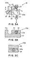
Fig. 3 (a) is a perspective view of a fine adjustment device included in the laser-welding head in the preferred embodiment;Fig. 3(b) is a sectional view of a first fine adjustment mechanism included in the fine adjustment device ofFig. 3(a) taken in the direction of the arrow B inFig. 3(a) ; and -
Fig. 3 (c) is a longitudinal sectional view of a second fine adjustment mechanism included in the fine adjustment device ofFig. 3(a) . - A laser-welding head in a preferred embodiment according to the present invention will be described by way of example with reference to the accompanying drawings.
- Referring to
Fig. 1 showing a laser-welding head (hereinafter referred to simply as "welding head") A in a perspective view, the welding head A is mounted on the extremity 1 of a robot arm of a welding robot to press parts of overlapping workpieces near a weld line during welding. More specifically, the welding head A presses overlapping parts of afirst workpiece 2 and asecond workpiece 3, such as steel plates, extending along a weld line while thefirst workpiece 2 and thesecond workpiece 3 are welded together with alaser beam 4. The welding head A includes, as essential components, a joiningmember 5, apressing unit 6 mounted on the joiningmember 5, and a laser-welding unit 7 mounted on thepressing unit 6. - The joining
member 5 is a flange matching a flange fixed to the extremity of the robot arm 1. The joiningmember 5 holding thepressing unit 6 is attached to the extremity of the robot arm 1. - The
pressing unit 6 has a support member 8, a pneumatic cylinder actuator 9 held on an upper part of the support member 8, amovable member 11 capable of vertically moving along a vertical,linear guide 10 formed on the support member 8, and apressing device 12 fixed to a lower part 11a of themovable member 11. - The support member 8 is mounted on the joining
member 5 so as to be substantially vertical to the surfaces of parts of theworkpieces - The pneumatic cylinder actuator 9 has an air cylinder 9b and a
piston rod 9a. The air cylinder 9b is attached to the support member 8. Thelower end 13 of thepiston rod 9a is fixed to themovable member 11. - As shown in
Fig. 1 , the pneumatic cylinder actuator 9 is a short-stroke cylinder actuator of a short length having a flat upper surface. When the pneumatic cylinder actuator 9 is viewed from above, the vertical movement of thepiston rod 9a can be hardly recognized. The stroke of thepiston rod 9a of the pneumatic cylinder actuator 9 is smaller than the diameter of the pressure-receiving surface of the piston rod 9. The stroke is, for example, in the range of 1 to 5 cm. The diameter of the pressure-receiving surface of thepiston rod 9a is, for example, in the range of 7 to 12 cm. The diameter of the pressure-receiving surface of thepiston rod 9a is equal to the diameter of thepiston rod 9a. - The extremity of the
piston rod 9a of the pneumatic cylinder actuator 9 is fixedly connected to anupper end part 14 of themovable member 11 to depress themovable member 11. The pneumatic cylinder actuator 9 is connected by apipe 31 to a pressure regulator 30 (air pressure control means), connected by apipe 33 to acompressor 32, i.e., a compressed-air source. Thepressure regulator 30 regulates the pressure of compressed air to be supplied to the pneumatic cylinder actuator 9 at a desired pressure. Thus, the pressure of the compressed air can be easily adjusted to a desired pressure and the compressed air of a desired pressure can be continuously supplied to the pneumatic cylinder actuator 9. Consequently, themovable member 11 is always urged by a fixed pressure applied thereto by the pneumatic cylinder actuator 9, the pressure exerted by the pneumatic cylinder actuator 9 can be changed. The pneumatic cylinder actuator 9 is capable of exerting a large pressure of, for example, 100 kgf. - The
movable member 11 having theupper end part 14 fixedly connected to theextremity 13 of thepiston rod 9a of the pneumatic cylinder actuator 9 can be moved vertically along thelinear guide 10 on the support member 8 by axially moving thepiston rod 9a of the pneumatic cylinder actuator 9. The laser-welding unit 7 is connected to an appropriate part, such as a central part, of the surface of themovable member 11. - The
pressing device 12 includes aroller support structure 15 fixed to a lower part 11a of themovable member 11, and aroller 16 supported for rotation on theroller support structure 15. - As shown in
Fig. 2 , theroller support structure 15 includes an L-shapedupper member 15a and an inverted-L-shapedintermediate member 15b joined to the horizontal lower surface of theupper member 15a, and aroller support member 15c joined to an inclined side surface of theintermediate member 15b. An upper part of a vertical wall of theupper member 15a is applied to and fastened with bolts to the lower part 11a of themovable member 11. The inclination of the inclined surface of theroller support member 15c is adjusted so that a flat side surface of theroller 16 extends along alaser beam 4. - The extension of the flat side surface of the
roller 16 along thelaser beam 4 signifies a state in which the flat side surface of theroller 16 is parallel to the profile of thefocused laser beam 4. For example, the flat side surface of theroller 16 is inclined at an angle in the range of 1° to 10° to a vertical. A touchingposition 42 where theroller 16 touches theworkpiece 2 is irradiated with thelaser beam 4 if helaser beam 4 is not focused. The touchingposition 42 is very close to afocal position 4a on which thelaser beam 4 is focused in a spot. Since the touchingposition 42 is very close to thefocal position 4a, theroller 16 is able to apply a pressure to parts of theworkpieces weld line 40 and thelaser beam 4 can be always focused at thefocal position 4a on theweld line 40. - The
upper member 15a and theintermediate member 15b are fastened together with bolts. Slots through which the bolts are passed are formed in the horizontal part of theupper member 15a to enable positional adjustment of theintermediate member 15b relative to theupper member 15a. Theintermediate member 15b and theroller support member 15c are fastened together with bolts. Slots through which the bolts are passed are formed in the inclined part of theintermediate member 15b to enable positional adjustment of theroller support member 15c relative to theintermediate member 15b. - The roller support structure thus constructed is capable of supporting the
roller 16 at a position near theweld line 40 on which thelaser beam 4 is focused for laser welding. - As shown in
Fig. 2 , theroller 16 is mounted on ashaft 15d supported for rotation in bearings fitted in a hole formed in a lower part of theroller support member 15c coaxially with theshaft 15d. Thus theroller 16 is supported on theroller support member 15c by theshaft 15d. As mentioned above, theroller 16 is supported on theroller support structure 15 such that the flat side surface of theroller 16 is parallel to the profile of thefocused laser beam 4. Therefore, theroller 16 is able to apply a pressure to parts of theworkpieces weld line 40. Since theroller 16 is supported for rotation on theroller support member 15c, theroller 16 is able to roll smoothly along the surface of theworkpiece 2. - The laser-
welding unit 7 includes a laserbeam projecting device 17 capable of projecting the laser beam on theworkpieces adjustment stage 18 holding the laserbeam projecting device 17 and capable of moving the laserbeam projecting device 17 laterally and vertically with respect to theweld line 40, and a laser beam projectingdevice support member 19 holding the fine-adjustment stage 18. - The laser
beam projecting device 17 projects, for example, a YAG laser beam (yttrium-aluminum-garnet laser beam) emitted by a YAG laser. A YAG laser beam can be focused in a small spot, which is desirable for precision welding. A YAG laser beam is easy to handle because the same can be transmitted by an optical-fiber cable. An optical-fiber cable may be connected to anupper part 17a of the laserbeam projecting device 17, a YAG laser beam may be transmitted through the optical-fiber cable to the laserbeam projecting device 17. The YAG laser beam can be thus transmitted by the optical-fiber cable to the laserbeam projecting device 17 without using a plurality of mirrors. Thus the laserbeam projecting device 17 is simple in construction. The welding head A of the present invention may employ a laser beam other than that emitted by a YAG laser, such as a laser beam emitted by a CO2 laser. - A
laser beam 4, such as a YAG laser beam, is transmitted by an optical-fiber cable, not shown, to theupper part 17a of the laserbeam projecting device 17. The laserbeam projecting device 17 projects thelaser beam 4 on parts to be welded of theworkpieces laser beam 4 is focused on theweld line 40 or at a position lightly in front of or slightly behind theweld line 40. - The laser beam projecting
device support member 19 has a holding part holding the fine-adjustment stage 18, and a base part fastened to themovable member 11. - Referring to
Figs. 3(a) to 3(c) , the fine-adjustment stage 18 includes a first fine-adjustment mechanism 20A for laterally moving the laserbeam projecting device 17 with respect to theweld line 40, and a second fine-adjustment mechanism 20B for vertically moving the laserbeam projecting device 17 with respect to theweld line 40. - As shown in
Figs. 3(a) and 3(b) , the first fine-adjustment mechanism 20A includes arack 21 having abase part 21a and provided with teeth 21b, ashaft 23 integrally provided with apinion 22 which engages the teeth 21b of therack 21 in its middle part, aslide block 24 holding theshaft 23 for rotation, and knobs 25 attached to the opposite ends of theshaft 23. Theslide block 24 is fixed to the laserbeam projecting device 17. Thebase part 21a of therack 21 is fixed to the second fine-adjustment mechanism 20B. Theknob 25 is rotated to move theslide block 24 to the right or to the left together with the laserbeam projecting device 17. - As shown in
Figs. 3(a) and 3(c) , the second fine-adjustment mechanism 20B includes aslide rack 26 provided withteeth 26a, ashaft 28 integrally provided with a pinion 27 which engages theteeth 26a of theslide rack 26 in its middle part, abase block 29 supporting theshaft 28 for rotation, and knobs 25 attached to the opposite ends of theshaft 28. Thebase block 29 is fastened to the laser beam projectingdevice support member 19. Thebase part 21a of therack 21 is fixed to theslide rack 26. Theknob 25 of the second fine-adjustment mechanism 20B is rotated to move theslide rack 26 vertically to move the laserbeam projecting device 17 vertically. - The first fine-
adjustment mechanism 20A and the second fine-adjustment mechanism 20B are operated properly to adjust the position of the laserbeam projecting device 17 so that thelaser beam 4 projected by the laserbeam projecting device 17 may fall at a desired position on theworkpieces - The fine-
adjustment stage 18 may be of any suitable construction other than the foregoing construction shown inFigs. 3(a) to 3(c) , provided that the fine-adjustment stage 18 is capable of adjusting the vertical and the lateral position of the laserbeam projecting device 17 with respect to theweld line 40. - A welding procedure using the welding head A will be described hereinafter.
- (1) The
knobs 25 of the fine-adjustment stage 18 are operated properly to position of the laserbeam projecting device 17 at a desired position. For example, the position of the laserbeam projecting device 17 is adjusted such that thelaser beam 4 is focused on a part of the workpiece near a part of the same depressed by theroller 16. - (2) The welding robot moves the extremity of the robot arm 1 along a predetermined path taught beforehand to the welding robot to move the welding head A so that the spot of the
focused laser beam 4 moves along theweld line 40. An edge of thefirst workpiece 2 placed on thesecond workpiece 3 corresponds to theweld line 40 shown inFig. 2 . - (3) The
roller 16 is in contact with a part of the surface of thefirst workpiece 2 near theweld line 40 and rolls along a line parallel to and close to theweld line 40 pressing thefirst workpiece 2 against thesecond workpiece 3 to press thefirst workpiece 2 and thesecond workpiece 3 close together. - (4) The
first workpiece 2 and thesecond workpiece 3 pressed together by theroller 16 are welded together with thelaser beam 4 projected by the laserbeam projecting device 17. - (5) Even if the surfaces of parts of the
workpieces weld line 40 undulate, theroller 16 pressed by the pneumatic cylinder actuator 9 is able to move vertically following the undulating surfaces of the parts of theworkpieces - (6) Since the pressure of the compressed air supplied to the pneumatic cylinder actuator 9 is regulated at a desired level by the
pressure regulator 30, a fixed pressure is applied to theworkpieces roller 16. - (7) Since the
roller 16 and the laserbeam projecting device 17 are fixedly mounted on themovable member 11, the laserbeam projecting device 17 moves vertically according to the vertical movement of theroller 16 along the undulating surface of thefirst workpiece 2, so that the distance between the laserbeam projecting device 17 and theweld line 40 remains constant and hence thelaser beam 4 is focused always correctly on theweld line 40. Since the parts to be welded of theworkpieces piston rod 9a of the pneumatic cylinder actuator 9 may be short. Thus the pneumatic cylinder actuator 9 has a small overall length, which is effective in forming the welding head A in small construction. - Thus the welding head of the present invention is capable of applying a fixed pressure to the workpieces regardless of the undulation of the surfaces of parts to be welded of the workpieces. The pressure to be applied by the welding head can be easily adjusted to a desired level and can be increased to a high pressure on the order of 100 kgf. The laser beam can be properly focused on the workpieces even if the surfaces of parts to be welded of the workpieces undulate. Since the lateral and vertical positions of the laser beam projecting device with respect to the weld line can be minutely adjusted by operating the fine-adjustment stage, the position of the spot of the laser beam on the workpieces can be easily changed.
- Although the invention has been described in its preferred embodiment, the present invention is not limited thereto in its practical application. For example, a laser beam emitted by a gas laser, such as a CO2 laser, or a laser beam emitted by a semiconductor laser may be used instead of the laser beam emitted by the YAG laser. A steel ball supported for rotation may be employed instead of the roller in pressing the workpieces. Although the welding head of the present invention has been described as being held on the robot arm of the welding robot, the welding head is applicable to various laser-welding machines other than the welding robot.
- As apparent from the foregoing description, the welding head of the present invention is capable of achieving laser welding applying a fixed pressure to parts to be welded of workpieces regardless of the undulation of the surfaces of the parts to be welded, of easily adjusting the pressure to be applied to the workpieces to a desired level, and of applying a high pressure on the order of 100 kgf to the workpieces.
- Since the
roller 16 is supported with its flat side surface inclined at an angle to the direction of travel of thelaser beam 4, such as a vertical, theroller 16 is able to apply a pressure to the workpieces at thetouching position 42, where theroller 16 touches the upper workpiece, very close to thefocal position 4a on which thelaser beam 4 is focused. Consequently, the laserbeam projecting device 17 is able to focus thelaser beam 4 always at thefocal position 4a on theweld line 40, and hence it is possible to prevent the deviation of the focal point on which thelaser beam 4 is focused from theweld line 40 due to the undulation of the surfaces of parts to be welded of the workpieces. - The welding head is capable of easily changing the focal position on which the laser beam is focused in lateral and vertical directions and hence the welding head is capable of readily dealing with the use of different laser beams.
Claims (17)
- A laser-welding head comprising:- a pressing device capable of moving along parts of workpieces near a weld line to press together the same parts of the workpieces,- a pressing unit for applying a predetermined pressure to the pressing device to press the pressing device toward the parts of the workpieces near the weld line, and- a laser beam projecting unit mounted on the pressing unit for movement together with the pressing device;wherein the pressing unit includes a pneumatic cylinder actuator for applying the predetermined pressure to the pressing device.
wherein a position of the laser beam projecting unit on the pressing unit is adjusted by a fine-adjustment device,
wherein the fine-adjustment device consists of first and second fine adjustment mechanisms for moving the laser beam projecting unit laterally with respect to the weld line and moving the same vertically,
wherein the laser beam projecting unit is held on the pressing unit by the fine adjustment device so as to be movable relative to position of the pressing device,
wherein the first and second fine-adjustment mechanisms are operable to adjust the position of the laser beam projecting device so that the laser beam projected by the laser beam projecting device falls at a desired position on the workpieces, wherein the first and second fine - adjustment devices include knobs being rotatable,
wherein the knob of the first fine - adjustment device is rotated to move the laser beam projecting device to the right or to the left of the weld line,
wherein the knob of the second fine-adjustment device is rotated to move the laser beam projecting device vertically. - The laser-welding head according to claim 1, wherein the pressing unit includes a support member and a movable member capable of moving relative to the support member, the pneumatic cylinder actuator has an air cylinder supported on the support member, and a piston rod having one end fastened to the movable member, the pressing device is supported on the movable member, and the laser beam projecting unit is mounted on the movable member.
- The laser-welding head according to claim 2, wherein the pneumatic cylinder actuator is connected to an air-pressure control means, and the air-pressure control means controls the pressure of compressed air supplied to the pneumatic cylinder actuator to apply a desired pressure to the movable member.
- The laser-welding head according to claim 2, wherein the movable member is movable relative to the support member along a linear guide formed on the support member.
- The laser-welding head according to claim 2, wherein a stroke of the piston rod of the pneumatic cylinder actuator is smaller than a diameter of a pressure-bearing surface of the piston rod.
- The laser-welding head according to claim 2, wherein a stroke of the piston rod of the pneumatic cylinder actuator is in the range of 1 to 5 cm.
- The laser-welding head according to claim 2, wherein the support member is mounted on an extremity of a robot arm.
- The laser-welding head according to claim 1, wherein the pressing device has a roller.
- The laser-welding head according to claim 8, wherein the roller is supported with its flat side surface inclined at a predetermined angle to a direction in which a laser beam projected by the laser beam projecting unit travels.
- The laser-welding head according to claim 9, wherein the roller is supported such that the flat side surface thereof extends along a profile of the laser beam projected and focused by the laser beam projecting unit.
- The laser-welding head according to claim 10, wherein a part of the workpiece with which the roller comes into contact is exposed to the laser beam when the laser beam is not focused.
- The laser-welding head according to claim 2, wherein the pressing device has a roller support structure fixed to the movable member, and a roller supported for rotation on the roller support structure.
- The laser-welding head according to claim 12, wherein the roller support structure includes: an upper member having an L-shaped cross section, an intermediate member having a substantially L-shaped cross section, having an inclined surface inclined outward with respect to the movable member, and joined to the upper member, and a roller support member joined to the inclined surface of the intermediate member to support the roller with its flat side surface inclined to a vertical.
- The laser-welding head according to claim 1, wherein the laser beam projecting unit projects a laser beam emitted by a YAG laser.
- The laser-welding head according to claim 1, wherein the pressing unit is mounted on an extremity of a robot arm.
- The laser-welding head according to claim 1, wherein parts to be welded together are overlapping parts of first and second workpieces.
- A robot provided with the laser-welding head according to any one of claims 1 to 16.
Applications Claiming Priority (2)
| Application Number | Priority Date | Filing Date | Title |
|---|---|---|---|
| JP2000392086 | 2000-12-25 | ||
| JP2000392086A JP3482452B2 (en) | 2000-12-25 | 2000-12-25 | Press head for laser welding |
Publications (3)
| Publication Number | Publication Date |
|---|---|
| EP1219384A2 EP1219384A2 (en) | 2002-07-03 |
| EP1219384A3 EP1219384A3 (en) | 2003-11-05 |
| EP1219384B1 true EP1219384B1 (en) | 2009-10-21 |
Family
ID=18858131
Family Applications (1)
| Application Number | Title | Priority Date | Filing Date |
|---|---|---|---|
| EP01130674A Expired - Lifetime EP1219384B1 (en) | 2000-12-25 | 2001-12-21 | Laser-welding head |
Country Status (6)
| Country | Link |
|---|---|
| US (1) | US6633018B2 (en) |
| EP (1) | EP1219384B1 (en) |
| JP (1) | JP3482452B2 (en) |
| KR (1) | KR100479698B1 (en) |
| AT (1) | ATE446160T1 (en) |
| DE (1) | DE60140247D1 (en) |
Families Citing this family (39)
| Publication number | Priority date | Publication date | Assignee | Title |
|---|---|---|---|---|
| AU2002253572A1 (en) * | 2001-04-27 | 2002-11-11 | Honda Giken Kogyo Kabushiki Kaisha | Method and appratus for laser beam welding of overlapping sheets |
| KR20040000995A (en) * | 2002-06-26 | 2004-01-07 | 현대자동차주식회사 | A work compressing device for laser welding system |
| FR2847187B1 (en) * | 2002-11-18 | 2005-09-23 | Le Controle Ind | SYSTEM AND METHOD FOR MOVING A POINT OF FOCUSING POWER LASER RADIATION |
| CN1953851B (en) * | 2004-05-06 | 2010-05-12 | 比克-维奥雷克斯有限公司 | Method of manufacturing razor head with laser weldment |
| EP2537626B1 (en) * | 2004-05-18 | 2019-06-26 | Kawasaki Jukogyo Kabushiki Kaisha | Body structure for rolling stock |
| KR100569021B1 (en) | 2004-06-17 | 2006-04-07 | 현대자동차주식회사 | Pressure roller device for laser welding |
| US7505504B2 (en) | 2004-10-07 | 2009-03-17 | Sango Co., Ltd. | Laser processing device |
| US20060112581A1 (en) * | 2004-12-01 | 2006-06-01 | Bernhard Nortmann | Alignment guide for a power tool |
| JP4804104B2 (en) * | 2005-10-21 | 2011-11-02 | 川崎重工業株式会社 | Railway vehicle side structure and manufacturing method thereof |
| JP4688634B2 (en) * | 2005-10-27 | 2011-05-25 | 川崎重工業株式会社 | Laser welding method and laser welding apparatus |
| US20070210046A1 (en) * | 2006-03-07 | 2007-09-13 | Jin-Sheng Lai | Roller adjusting device of optical laser-lens seat |
| KR100764714B1 (en) | 2006-06-20 | 2007-10-09 | 현대자동차주식회사 | Laser welding part press device |
| DE102007002856B4 (en) * | 2007-01-15 | 2012-02-09 | Edag Gmbh & Co. Kgaa | Device for flanging and welding or soldering of components |
| DE102007053737B4 (en) * | 2007-11-12 | 2019-01-17 | Sauer Gmbh Lasertec | Multi-axis machining machine connector Elasticity control method |
| KR100853617B1 (en) | 2008-03-24 | 2008-08-22 | 김유찬 | Automatic pressure regulating material pressurizing device and method |
| US8334477B1 (en) * | 2008-07-21 | 2012-12-18 | Roll Forming Corporation | Method and apparatus for laser welding elongated workpieces |
| FR2947470A1 (en) * | 2009-07-02 | 2011-01-07 | Air Liquide Welding France | SYSTEM FOR POSITIONING A LASER HEAD WITH MULTIPLE AXES |
| JP5496632B2 (en) * | 2009-12-14 | 2014-05-21 | 川崎重工業株式会社 | Laser processing head and laser processing apparatus including the same |
| AT509520B1 (en) * | 2010-03-10 | 2012-07-15 | Dtec Gmbh | WELDING DEVICE AND WELDING PROCESS |
| US8299392B2 (en) * | 2010-04-23 | 2012-10-30 | Benecor, Inc. | Rotating laser welding pressure unit |
| WO2012135732A1 (en) * | 2011-03-30 | 2012-10-04 | Illinois Tool Works Inc. | System for and method of welding large panel assemblies using a welding robot and a pressing component |
| JP5207156B2 (en) * | 2011-07-19 | 2013-06-12 | 日産自動車株式会社 | Dissimilar materials joining equipment |
| DE202011052291U1 (en) * | 2011-12-14 | 2012-01-30 | Scansonic Mi Gmbh | Device for material processing by means of a laser beam |
| JP5486105B1 (en) * | 2013-04-09 | 2014-05-07 | テクノコート株式会社 | Laser overlay welding method, laser welding method, laser cutting method, laser quenching method, laser overlay welding apparatus, laser welding apparatus, laser cutting apparatus and laser quenching apparatus |
| CN106563879B (en) * | 2016-11-08 | 2019-05-17 | 深圳市锐博精创科技有限公司 | Prepressing type laser welding head |
| KR101949586B1 (en) | 2017-03-28 | 2019-04-29 | 신철우 | Laser welding apparatus |
| CN108406143B (en) * | 2018-04-04 | 2020-10-30 | 大族激光科技产业集团股份有限公司 | A flexible pressure roller mechanism and adaptive laser welding device |
| CN108581238B (en) * | 2018-04-10 | 2020-06-26 | 威克锐光电科技(苏州)有限公司 | Laser welding pressing device and pressing welding method |
| CN109590757B (en) * | 2018-12-28 | 2024-06-21 | 中冶南方工程技术有限公司 | Laser welding device with pre-leveling function |
| CN110181821B (en) * | 2019-06-21 | 2023-12-29 | 南京帝耐激光科技有限公司 | Laser welding car lamp system and method |
| CN110576261B (en) * | 2019-08-21 | 2021-06-25 | 中车青岛四方机车车辆股份有限公司 | Laser stitch welding device and welding method thereof |
| CN111805083A (en) * | 2020-08-03 | 2020-10-23 | 威克锐光电科技(苏州)有限公司 | A driven pressing device for laser welding |
| CN113263281B (en) * | 2021-05-18 | 2022-02-11 | 广州中益机械有限公司 | Method for welding thin plate and thick plate |
| CN113523571B (en) * | 2021-06-30 | 2023-07-14 | 北京航星机器制造有限公司 | Laser welding tooling and welding method for rudder wing product with skin skeleton structure |
| CN113523566B (en) * | 2021-08-10 | 2023-09-15 | 速博达(深圳)自动化有限公司 | Laser welding lamination coaxial compensation mechanism, battery module welding tool and method |
| US12472580B2 (en) * | 2022-06-01 | 2025-11-18 | Caterpillar Inc. | Laser handheld trimming and welding device |
| CN116460438B (en) * | 2023-04-28 | 2026-04-10 | 武汉凯奇冶金焊接设备制造有限责任公司 | A support wheel device for a laser welding machine and a laser welding machine |
| CN118023699A (en) * | 2024-03-08 | 2024-05-14 | 唐山开元焊接自动化技术研究所有限公司 | Integrated laser stitch welding device and use method |
| CN118081016B (en) * | 2024-04-02 | 2024-07-23 | 江门市朗达锂电池有限公司 | A laser welding machine for lithium battery production |
Citations (1)
| Publication number | Priority date | Publication date | Assignee | Title |
|---|---|---|---|---|
| WO1997037808A1 (en) * | 1996-04-04 | 1997-10-16 | Kuka Schweissanlagen Gmbh | Welding and/or cutting device |
Family Cites Families (13)
| Publication number | Priority date | Publication date | Assignee | Title |
|---|---|---|---|---|
| JPH0344387Y2 (en) | 1986-12-19 | 1991-09-18 | ||
| FR2636554B1 (en) * | 1988-09-20 | 1992-12-04 | Peugeot | DEVICE FOR WELDING SHEETS OR THE LIKE BY A LASER BEAM |
| JPH0357580A (en) | 1989-07-26 | 1991-03-12 | Ishikawajima Harima Heavy Ind Co Ltd | laser welding equipment |
| JPH0480682U (en) | 1990-11-26 | 1992-07-14 | ||
| US5142118A (en) * | 1991-05-14 | 1992-08-25 | Progressive Tool & Industries Co. | Laser welding unit |
| JPH05337669A (en) | 1992-06-10 | 1993-12-21 | Toshiba Corp | Laser processing equipment |
| DE9319146U1 (en) * | 1993-12-14 | 1995-03-16 | Kuka Schweißanlagen + Roboter GmbH, 86165 Augsburg | Device for welding and / or cutting |
| DE4403999C2 (en) * | 1994-02-09 | 1996-12-19 | Ford Werke Ag | Device for welding two- or multi-layer sheet metal components along an interrupted or continuous weld |
| JPH10113783A (en) | 1996-10-07 | 1998-05-06 | Horie Metal Co Ltd | Laser welding method for galvanized steel sheet |
| JPH11226763A (en) | 1998-02-17 | 1999-08-24 | Nissan Motor Co Ltd | Laser welding equipment |
| DE19854217C2 (en) * | 1998-11-24 | 2002-05-02 | Bayerische Motoren Werke Ag | Laser beam welding process for lap seams on coated metal sheets |
| JP3596329B2 (en) * | 1999-02-16 | 2004-12-02 | 日産自動車株式会社 | Laser welding apparatus and laser welding method |
| JP2000288756A (en) * | 1999-04-02 | 2000-10-17 | Nissan Motor Co Ltd | Laser welding apparatus and laser welding method |
-
2000
- 2000-12-25 JP JP2000392086A patent/JP3482452B2/en not_active Expired - Lifetime
-
2001
- 2001-12-18 US US10/020,189 patent/US6633018B2/en not_active Expired - Lifetime
- 2001-12-21 AT AT01130674T patent/ATE446160T1/en not_active IP Right Cessation
- 2001-12-21 DE DE60140247T patent/DE60140247D1/en not_active Expired - Lifetime
- 2001-12-21 EP EP01130674A patent/EP1219384B1/en not_active Expired - Lifetime
- 2001-12-22 KR KR10-2001-0083149A patent/KR100479698B1/en not_active Expired - Fee Related
Patent Citations (1)
| Publication number | Priority date | Publication date | Assignee | Title |
|---|---|---|---|---|
| WO1997037808A1 (en) * | 1996-04-04 | 1997-10-16 | Kuka Schweissanlagen Gmbh | Welding and/or cutting device |
Also Published As
| Publication number | Publication date |
|---|---|
| JP3482452B2 (en) | 2003-12-22 |
| KR100479698B1 (en) | 2005-03-30 |
| KR20020052961A (en) | 2002-07-04 |
| US20020079295A1 (en) | 2002-06-27 |
| JP2002192375A (en) | 2002-07-10 |
| US6633018B2 (en) | 2003-10-14 |
| EP1219384A3 (en) | 2003-11-05 |
| DE60140247D1 (en) | 2009-12-03 |
| EP1219384A2 (en) | 2002-07-03 |
| ATE446160T1 (en) | 2009-11-15 |
Similar Documents
| Publication | Publication Date | Title |
|---|---|---|
| US6633018B2 (en) | Laser welding head with associated roller | |
| US7748593B2 (en) | Friction stir welding apparatus and method of operating same | |
| US5142118A (en) | Laser welding unit | |
| JP5864557B2 (en) | Method and apparatus for laser joining thin metal plate parts | |
| JP3394750B2 (en) | Work pressing device | |
| KR100515627B1 (en) | Laser welding method and laser welding apparatus | |
| EP1273383A1 (en) | Welding system | |
| EP1600241B1 (en) | Focus adjuster for laser beam machine | |
| US20020079299A1 (en) | Laser beam projector | |
| WO1989011949A2 (en) | Beam delivery apparatus | |
| US5493095A (en) | Laser beam divergence compensation apparatus | |
| JP4688634B2 (en) | Laser welding method and laser welding apparatus | |
| JPH11226763A (en) | Laser welding equipment | |
| JP3109261B2 (en) | Laser welding unit | |
| JP2000061669A (en) | Laser processing apparatus and its processing method | |
| JPH09141493A (en) | Butt jig | |
| CN114144277A (en) | Bonded product manufacturing apparatus | |
| JP2004130323A (en) | Laser welding apparatus and laser welding method | |
| JP2001191191A (en) | Processing head for laser welding robot | |
| JP3396467B2 (en) | Lap welding equipment for sheet metal | |
| JP4978111B2 (en) | Laser welding method and apparatus | |
| CN100513048C (en) | Laser beam welding method and apparatus | |
| JPH11156574A (en) | Laser welding method and apparatus | |
| JP2002224842A (en) | Seam welding method and welding locus guidance device | |
| JP2025088278A (en) | Laser Welding Equipment |
Legal Events
| Date | Code | Title | Description |
|---|---|---|---|
| PUAI | Public reference made under article 153(3) epc to a published international application that has entered the european phase |
Free format text: ORIGINAL CODE: 0009012 |
|
| 17P | Request for examination filed |
Effective date: 20011221 |
|
| AK | Designated contracting states |
Kind code of ref document: A2 Designated state(s): AT BE CH CY DE DK ES FI FR GB GR IE IT LI LU MC NL PT SE TR |
|
| AX | Request for extension of the european patent |
Free format text: AL;LT;LV;MK;RO;SI |
|
| RIN1 | Information on inventor provided before grant (corrected) |
Inventor name: NISHIO, MAMORU Inventor name: UNO, TOMOYUKI Inventor name: MURATA, TAKAYUKI Inventor name: SATOH, OSAMU Inventor name: UEHARA, HIROTAKA Inventor name: SHIKODA, SHIGEKAZU Inventor name: KUBOTA, TETSUYA |
|
| RIN1 | Information on inventor provided before grant (corrected) |
Inventor name: MURATA, TAKAYUKI Inventor name: NISHIO, MAMORU Inventor name: UEHARA, HIROTAKA Inventor name: SHIKODA, SHIGEKAZU Inventor name: UNO, TOMOYUKI Inventor name: SATOH, OSAMU Inventor name: KUBOTA, TETSUYA |
|
| RIN1 | Information on inventor provided before grant (corrected) |
Inventor name: UNO, TOMOYUKI Inventor name: SHIKODA, SHIGEKAZU Inventor name: UEHARA, HIROTAKA Inventor name: SATOH, OSAMU Inventor name: NISHIO, MAMORU Inventor name: KUBOTA, TETSUYA Inventor name: MURATA, TAKAYUKI |
|
| RIN1 | Information on inventor provided before grant (corrected) |
Inventor name: UEHARA, HIROTAKA Inventor name: NISHIO, MAMORU Inventor name: UNO, TOMOYUKI Inventor name: MURATA, TAKAYUKI Inventor name: KUBOTA, TETSUYA Inventor name: SHIKODA, SHIGEKAZU Inventor name: SATOH, OSAMU |
|
| PUAL | Search report despatched |
Free format text: ORIGINAL CODE: 0009013 |
|
| AK | Designated contracting states |
Kind code of ref document: A3 Designated state(s): AT BE CH CY DE DK ES FI FR GB GR IE IT LI LU MC NL PT SE TR |
|
| AX | Request for extension of the european patent |
Extension state: AL LT LV MK RO SI |
|
| RIC1 | Information provided on ipc code assigned before grant |
Ipc: 7B 23K 26/24 B Ipc: 7B 23K 26/42 A Ipc: 7B 23K 26/10 B |
|
| AKX | Designation fees paid |
Designated state(s): AT BE CH CY DE DK ES FI FR GB GR IE IT LI LU MC NL PT SE TR |
|
| 17Q | First examination report despatched |
Effective date: 20050223 |
|
| 17Q | First examination report despatched |
Effective date: 20050223 |
|
| GRAP | Despatch of communication of intention to grant a patent |
Free format text: ORIGINAL CODE: EPIDOSNIGR1 |
|
| GRAS | Grant fee paid |
Free format text: ORIGINAL CODE: EPIDOSNIGR3 |
|
| GRAA | (expected) grant |
Free format text: ORIGINAL CODE: 0009210 |
|
| AK | Designated contracting states |
Kind code of ref document: B1 Designated state(s): AT BE CH CY DE DK ES FI FR GB GR IE IT LI LU MC NL PT SE TR |
|
| REG | Reference to a national code |
Ref country code: GB Ref legal event code: FG4D |
|
| REG | Reference to a national code |
Ref country code: CH Ref legal event code: EP |
|
| REG | Reference to a national code |
Ref country code: IE Ref legal event code: FG4D |
|
| REF | Corresponds to: |
Ref document number: 60140247 Country of ref document: DE Date of ref document: 20091203 Kind code of ref document: P |
|
| NLV1 | Nl: lapsed or annulled due to failure to fulfill the requirements of art. 29p and 29m of the patents act | ||
| PG25 | Lapsed in a contracting state [announced via postgrant information from national office to epo] |
Ref country code: SE Free format text: LAPSE BECAUSE OF FAILURE TO SUBMIT A TRANSLATION OF THE DESCRIPTION OR TO PAY THE FEE WITHIN THE PRESCRIBED TIME-LIMIT Effective date: 20091021 Ref country code: PT Free format text: LAPSE BECAUSE OF FAILURE TO SUBMIT A TRANSLATION OF THE DESCRIPTION OR TO PAY THE FEE WITHIN THE PRESCRIBED TIME-LIMIT Effective date: 20100222 Ref country code: FI Free format text: LAPSE BECAUSE OF FAILURE TO SUBMIT A TRANSLATION OF THE DESCRIPTION OR TO PAY THE FEE WITHIN THE PRESCRIBED TIME-LIMIT Effective date: 20091021 Ref country code: ES Free format text: LAPSE BECAUSE OF FAILURE TO SUBMIT A TRANSLATION OF THE DESCRIPTION OR TO PAY THE FEE WITHIN THE PRESCRIBED TIME-LIMIT Effective date: 20100201 |
|
| PG25 | Lapsed in a contracting state [announced via postgrant information from national office to epo] |
Ref country code: BE Free format text: LAPSE BECAUSE OF FAILURE TO SUBMIT A TRANSLATION OF THE DESCRIPTION OR TO PAY THE FEE WITHIN THE PRESCRIBED TIME-LIMIT Effective date: 20091021 Ref country code: AT Free format text: LAPSE BECAUSE OF FAILURE TO SUBMIT A TRANSLATION OF THE DESCRIPTION OR TO PAY THE FEE WITHIN THE PRESCRIBED TIME-LIMIT Effective date: 20091021 |
|
| PG25 | Lapsed in a contracting state [announced via postgrant information from national office to epo] |
Ref country code: DK Free format text: LAPSE BECAUSE OF FAILURE TO SUBMIT A TRANSLATION OF THE DESCRIPTION OR TO PAY THE FEE WITHIN THE PRESCRIBED TIME-LIMIT Effective date: 20091021 Ref country code: MC Free format text: LAPSE BECAUSE OF NON-PAYMENT OF DUE FEES Effective date: 20100701 |
|
| REG | Reference to a national code |
Ref country code: CH Ref legal event code: PL |
|
| PLBE | No opposition filed within time limit |
Free format text: ORIGINAL CODE: 0009261 |
|
| STAA | Information on the status of an ep patent application or granted ep patent |
Free format text: STATUS: NO OPPOSITION FILED WITHIN TIME LIMIT |
|
| 26N | No opposition filed |
Effective date: 20100722 |
|
| GBPC | Gb: european patent ceased through non-payment of renewal fee |
Effective date: 20100121 |
|
| PG25 | Lapsed in a contracting state [announced via postgrant information from national office to epo] |
Ref country code: CH Free format text: LAPSE BECAUSE OF NON-PAYMENT OF DUE FEES Effective date: 20091231 Ref country code: LI Free format text: LAPSE BECAUSE OF NON-PAYMENT OF DUE FEES Effective date: 20091231 Ref country code: GR Free format text: LAPSE BECAUSE OF FAILURE TO SUBMIT A TRANSLATION OF THE DESCRIPTION OR TO PAY THE FEE WITHIN THE PRESCRIBED TIME-LIMIT Effective date: 20100122 Ref country code: IE Free format text: LAPSE BECAUSE OF NON-PAYMENT OF DUE FEES Effective date: 20091221 |
|
| PG25 | Lapsed in a contracting state [announced via postgrant information from national office to epo] |
Ref country code: GB Free format text: LAPSE BECAUSE OF NON-PAYMENT OF DUE FEES Effective date: 20100121 |
|
| PG25 | Lapsed in a contracting state [announced via postgrant information from national office to epo] |
Ref country code: LU Free format text: LAPSE BECAUSE OF NON-PAYMENT OF DUE FEES Effective date: 20091221 |
|
| PG25 | Lapsed in a contracting state [announced via postgrant information from national office to epo] |
Ref country code: TR Free format text: LAPSE BECAUSE OF FAILURE TO SUBMIT A TRANSLATION OF THE DESCRIPTION OR TO PAY THE FEE WITHIN THE PRESCRIBED TIME-LIMIT Effective date: 20091021 |
|
| PG25 | Lapsed in a contracting state [announced via postgrant information from national office to epo] |
Ref country code: CY Free format text: LAPSE BECAUSE OF FAILURE TO SUBMIT A TRANSLATION OF THE DESCRIPTION OR TO PAY THE FEE WITHIN THE PRESCRIBED TIME-LIMIT Effective date: 20091021 |
|
| PG25 | Lapsed in a contracting state [announced via postgrant information from national office to epo] |
Ref country code: NL Free format text: LAPSE BECAUSE OF FAILURE TO SUBMIT A TRANSLATION OF THE DESCRIPTION OR TO PAY THE FEE WITHIN THE PRESCRIBED TIME-LIMIT Effective date: 20091021 |
|
| REG | Reference to a national code |
Ref country code: FR Ref legal event code: PLFP Year of fee payment: 15 |
|
| REG | Reference to a national code |
Ref country code: FR Ref legal event code: PLFP Year of fee payment: 16 |
|
| PGFP | Annual fee paid to national office [announced via postgrant information from national office to epo] |
Ref country code: DE Payment date: 20161213 Year of fee payment: 16 Ref country code: FR Payment date: 20161111 Year of fee payment: 16 |
|
| PGFP | Annual fee paid to national office [announced via postgrant information from national office to epo] |
Ref country code: IT Payment date: 20161221 Year of fee payment: 16 |
|
| REG | Reference to a national code |
Ref country code: DE Ref legal event code: R119 Ref document number: 60140247 Country of ref document: DE |
|
| REG | Reference to a national code |
Ref country code: FR Ref legal event code: ST Effective date: 20180831 |
|
| PG25 | Lapsed in a contracting state [announced via postgrant information from national office to epo] |
Ref country code: IT Free format text: LAPSE BECAUSE OF NON-PAYMENT OF DUE FEES Effective date: 20171221 Ref country code: DE Free format text: LAPSE BECAUSE OF NON-PAYMENT OF DUE FEES Effective date: 20180703 Ref country code: FR Free format text: LAPSE BECAUSE OF NON-PAYMENT OF DUE FEES Effective date: 20180102 |