EP1219333A1 - Air trap for liquid circulation line - Google Patents
Air trap for liquid circulation line Download PDFInfo
- Publication number
- EP1219333A1 EP1219333A1 EP01130602A EP01130602A EP1219333A1 EP 1219333 A1 EP1219333 A1 EP 1219333A1 EP 01130602 A EP01130602 A EP 01130602A EP 01130602 A EP01130602 A EP 01130602A EP 1219333 A1 EP1219333 A1 EP 1219333A1
- Authority
- EP
- European Patent Office
- Prior art keywords
- liquid
- circulation line
- filter
- liquid circulation
- air
- Prior art date
- Legal status (The legal status is an assumption and is not a legal conclusion. Google has not performed a legal analysis and makes no representation as to the accuracy of the status listed.)
- Granted
Links
- 239000007788 liquid Substances 0.000 title claims abstract description 101
- 239000011148 porous material Substances 0.000 claims abstract description 13
- 239000012466 permeate Substances 0.000 claims abstract description 6
- 238000011144 upstream manufacturing Methods 0.000 claims abstract description 4
- 230000000052 comparative effect Effects 0.000 description 5
- 239000002826 coolant Substances 0.000 description 5
- 238000001816 cooling Methods 0.000 description 5
- 238000010586 diagram Methods 0.000 description 2
- 238000001914 filtration Methods 0.000 description 2
- 230000005484 gravity Effects 0.000 description 2
- 238000005259 measurement Methods 0.000 description 2
- 239000012071 phase Substances 0.000 description 2
- -1 polyethylene Polymers 0.000 description 2
- 239000000047 product Substances 0.000 description 2
- 229920000914 Metallic fiber Polymers 0.000 description 1
- 239000002033 PVDF binder Substances 0.000 description 1
- 239000004952 Polyamide Substances 0.000 description 1
- 239000004698 Polyethylene Substances 0.000 description 1
- 239000004743 Polypropylene Substances 0.000 description 1
- 239000004699 Ultra-high molecular weight polyethylene Substances 0.000 description 1
- 230000015572 biosynthetic process Effects 0.000 description 1
- 229920002678 cellulose Polymers 0.000 description 1
- 239000001913 cellulose Substances 0.000 description 1
- 238000010276 construction Methods 0.000 description 1
- 230000007423 decrease Effects 0.000 description 1
- 238000001704 evaporation Methods 0.000 description 1
- 230000008020 evaporation Effects 0.000 description 1
- 239000012530 fluid Substances 0.000 description 1
- 238000009434 installation Methods 0.000 description 1
- 239000007791 liquid phase Substances 0.000 description 1
- 239000000463 material Substances 0.000 description 1
- 230000013011 mating Effects 0.000 description 1
- 229920003229 poly(methyl methacrylate) Polymers 0.000 description 1
- 229920002647 polyamide Polymers 0.000 description 1
- 229920000515 polycarbonate Polymers 0.000 description 1
- 239000004417 polycarbonate Substances 0.000 description 1
- 229920000728 polyester Polymers 0.000 description 1
- 229920000573 polyethylene Polymers 0.000 description 1
- 239000004926 polymethyl methacrylate Substances 0.000 description 1
- 229920001155 polypropylene Polymers 0.000 description 1
- 229920000915 polyvinyl chloride Polymers 0.000 description 1
- 239000004800 polyvinyl chloride Substances 0.000 description 1
- 229920002981 polyvinylidene fluoride Polymers 0.000 description 1
- 230000000087 stabilizing effect Effects 0.000 description 1
- 229920000785 ultra high molecular weight polyethylene Polymers 0.000 description 1
- XLYOFNOQVPJJNP-UHFFFAOYSA-N water Substances O XLYOFNOQVPJJNP-UHFFFAOYSA-N 0.000 description 1
- 238000003466 welding Methods 0.000 description 1
Images


Classifications
-
- B—PERFORMING OPERATIONS; TRANSPORTING
- B01—PHYSICAL OR CHEMICAL PROCESSES OR APPARATUS IN GENERAL
- B01D—SEPARATION
- B01D19/00—Degasification of liquids
- B01D19/0031—Degasification of liquids by filtration
Definitions
- the present invention relates to an air trap for liquid circulation line. More particularly, it relates to an air trap for a liquid circulation line for circulating a liquid such as a coolant or the like, capable of trapping bubbles in the liquid circulating through the liquid circulation line to prevent the bubbles produced in the circulation line from entering into a circulating pump.
- cooling fans have been used for cooling systems of CPUs in personal computers or the like.
- water-cooled cooling systems are partially used in personal computers or the like because of their higher heat efficiency.
- the gravity type air trap does not function well if a notebook-size personal computer equipped with such an air trap is used under the circumstances turned upside down.
- the filter type air trap of Fig. 6 has a problem in that the coolant in the circulation line decreases in quantity by evaporation during long use.
- the present inventors have intensively researched in order to achieve the above object, and found that by trapping bubbles generated in a coolant in a part of the circulation line, instead of removing therefrom, it is possible to keep an amount of the coolant in the circulation line constant as well as to prevent the bubbles from entering into the pump.
- an air trap for liquid circulation lines comprising an air reservoir provided in a liquid circulation line, and a hydrophilic filter arranged in said air reservoir to separate an upstream of a flow path therein from a downstream side thereof, said filter having liquid-permeability and air bubble- impermeability.
- a hydrophilic filter having pores which meet conditions defined by the following equation (1): P ⁇ 4h/d where P represents a gas pressure, d is a diameter of the pores of the filter, and h is a surface tension of the liquid.
- the air reservoir is composed of an internal space of a container arranged in and spaced from a housing, which has at a proximal end thereof a liquid inlet for liquid from the liquid circulation line and at a distal end thereof a liquid outlet for liquid to the liquid circulation line, and communicated with the liquid inlet at a distal end thereof.
- the container is provided in its wall with at least one window to allow the internal space thereof to communicate with the outer space formed between the housing and the container.
- the container is provided at its wall with at least one filter so as to close the at least one window thereof with the filter.
- the air reservoir may be composed of an internal space of a flat housing provided in opposite flat walls thereof with an inlet for a liquid from the liquid circulation line and an outlet for a liquid to the circulation line respectively.
- the housing is further provided in the interior thereof with a filter so that the internal space thereof is partitioned to two spaces, i.e., a liquid inlet side and a liquid outlet side.
- an air trap of the present invention comprises an air reservoir (2) to be arranged in a liquid circulation line (not illustrated in the drawing), and a hydrophilic filter (3) which permits a liquid to permeate but does not permit gas bubbles to permeate and which is arranged in the air reservoir to separate an upstream side of the liquid circulation line from the downstream side of the liquid circulation line.
- the filter (3) has a number of pores (31), which resemble capillaries, as shown in Fig. 3. If a liquid phase is separated from a gas phase by the filter (3), the pores (31) of the filter (3) are filled with the liquid and the filter (3) gets a pressure P on its one surface from the side of the gas and a pressure P h on the opposite surface from the side of the liquid (a pressure due to surface tension), as shown in Fig. 4. In order for the gas to cause the liquid to push out of the pores (31), the gas is required to have a pressure higher than the surface tension of the liquid. A pressure equivalent to the surface tension of a liquid is generally called as a bubble point pressure.
- the filter (3) used in the air trap of the present invention has pores (31) which satisfies the requirement of P ⁇ P b , namely, the conditions as defined by the equation: P ⁇ 4h/d.
- P ⁇ P b the pressure on the side of the gas phase
- the filter (3) used in the air trap of the present invention has pores (31) which satisfies the requirement of P ⁇ P b , namely, the conditions as defined by the equation: P ⁇ 4h/d.
- the diameter h of the pores should be smaller than 29.3 ⁇ m (h ⁇ 29.3 ⁇ m).
- the air reservoir (2) is composed of an internal space of a container (4) arranged in the housing (1) and spaced therefrom to form a space between them.
- the housing (1) has at a proximal end thereof a liquid inlet (11) for the liquid from the liquid circulation line and at a distal end a liquid outlet (12) for the liquid to the liquid circulation line.
- the container (4) is closed at a distal end thereof but opened at a proximal end thereof to form a liquid communication with the liquid inlet (11).
- the container (4) is further provided in its side wall with at least one window (42) covered with the filter (3).
- An area of the window (42), i.e., an effective filtration area of the filter (3) is determined in consideration of a fluid resistance of the filter (3) and reduction in the filtering area caused by the trapped air, so that the liquid pressure acting on the filter, that is, the pressure on the side of the gas can not exceed the liquid pressure at the liquid inlet (11).
- the filter (3) there may be used cellulose, ultra-high-molecular-weight polyethylene, polyethylene, polymethylmethacrylate, polypropylene, polyvinyl chloride, polycarbonate, polytetrafuloroethylene, polyvinylidene fluoride, polyester, polyamide, metallic fiber and the like.
- the liquid which is circulated through the liquid circulation line by the pump (not illustrated in the drawing), enters into the air reservoir (2) through the liquid inlet (11) of the air trap, passes through the filter (3) and flows out of the liquid outlet (12) through the outer space formed between the container (4) and the housing (1). If the gas bubbles are contained in the liquid flowing into the air reservoir (2), the bubbles are trapped by the filter and remain in the air reservoir (2). Therefore, there is no possibility for the bubbles to push out through the air trap.
- the container (4) is not necessarily closed at the distal end as shown in Fig. 1.
- the container (4) may be provided at the distal end thereof with a window (42) covered with a filter (3).
- the air trap shown in Fig. 2 comprises a flat housing (5) provided with an air reservoir (6).
- the air reservoir (6) is constituted by an internal space of the flat housing (5), which is provided with a liquid inlet (51) for the liquid entering into the internal space from a liquid circulation line and a liquid outlet (52) for the liquid flowing out to the liquid circulation line.
- the inlet (51) and outlet (52) are provided oppositely from each other, vertically and axially symmetric to each other relative to the plane surface of the housing (5), respectively.
- the internal space of the housing (5) is partitioned by a filter (7) into two spaces, i.e., a space on a liquid inlet side and a space on a liquid outlet side.
- liquid inlet (51) and the liquid outlet (52) are not necessarily arranged vertically and axially symmetric to each other, in so far as they are arranged oppositely from each other relative to the plane surface of the housing (5).
- the housing (5) having a configuration as shown in Fig.
- 2 may be constructed, for example, by preparing two identical flat members (5a), (5b) each having a recess (53), (54) formed in one side thereof and a cylindrical projection serving as a liquid inlet (51) or a liquid outlet (52) formed in the other side thereof, mating the two flat members (5a), (5b) together with a filter (7) placed between them so that the liquid inlet (51) and the liquid outlet (52) are located axially symmetric to each other, and then welding the flat members (5a) and (5b).
- the recessed portions (53) and (54) are faced each other to form a space partitioned by the filter into an air reservoir (6) and a space communicated with the liquid outlet (52).
- the depth of the recessed portion (53) forming the air reservoir (6) is determined so that the liquid in the recessed portion (53) always come into contact with the whole area of the filter (7) to avoid the dependency of the flow rate of the liquid passing through the filter (7) on the installation mode of the air trap (specifically whether the recessed portions (53), (54) are set vertically or horizontally).
- the depth of the recessed portion ranges, preferably from about 0.1 to about 4.0 mm and, more preferably, from 0.5 to 2.0 mm.
- the use of the air traps according to the present invention makes it possible to stabilize the discharge rate of the pumps of the cooling systems.
Landscapes
- Chemical & Material Sciences (AREA)
- Chemical Kinetics & Catalysis (AREA)
- Degasification And Air Bubble Elimination (AREA)
Abstract
where P represents a gas pressure, d is a diameter of the pores of the filter, and h is a surface tension of the liquid.
Description
- The present invention relates to an air trap for liquid circulation line. More particularly, it relates to an air trap for a liquid circulation line for circulating a liquid such as a coolant or the like, capable of trapping bubbles in the liquid circulating through the liquid circulation line to prevent the bubbles produced in the circulation line from entering into a circulating pump.
- Generally, cooling fans have been used for cooling systems of CPUs in personal computers or the like. Alternatively, water-cooled cooling systems are partially used in personal computers or the like because of their higher heat efficiency.
- In such personal computers, large-sized products or desktop type personal computers may be equipped with a circulating pump with a large capacity, and thus they have no trouble with the capacity of the pump. In contrast therewith, small-sized products such as, for example, notebook-size personal computers have limits in size and weight and thus it is obliged to use a circulating pump with a small capacity. However, such small sized water-cooling systems have difficulties in constant discharge rate of the pumps because of formation of bubbles in the circulation line. In order to ensure the constant discharge rate, it is required to provide any mechanism for removing such bubbles from the coolant. For this purpose, there have been used gravity type air traps as shown in Fig. 5 or filter type air traps as shown in Fig. 6. However, the gravity type air trap does not function well if a notebook-size personal computer equipped with such an air trap is used under the circumstances turned upside down. On the other hand, the filter type air trap of Fig. 6 has a problem in that the coolant in the circulation line decreases in quantity by evaporation during long use.
- It is therefore an object of the present invention to provide an air trap for liquid circulation line, which is capable of stabilizing a discharge rate of a pump by trapping bubbles produced in a liquid circulating in a liquid circulation line to prevent the bubbles from entering into a pump.
- The present inventors have intensively researched in order to achieve the above object, and found that by trapping bubbles generated in a coolant in a part of the circulation line, instead of removing therefrom, it is possible to keep an amount of the coolant in the circulation line constant as well as to prevent the bubbles from entering into the pump.
- According to the present invention, there is provided an air trap for liquid circulation lines, comprising an air reservoir provided in a liquid circulation line, and a hydrophilic filter arranged in said air reservoir to separate an upstream of a flow path therein from a downstream side thereof, said filter having liquid-permeability and air bubble- impermeability. In that case, it is preferred to use a hydrophilic filter having pores which meet conditions defined by the following equation (1):
- The air reservoir is composed of an internal space of a container arranged in and spaced from a housing, which has at a proximal end thereof a liquid inlet for liquid from the liquid circulation line and at a distal end thereof a liquid outlet for liquid to the liquid circulation line, and communicated with the liquid inlet at a distal end thereof. The container is provided in its wall with at least one window to allow the internal space thereof to communicate with the outer space formed between the housing and the container. The container is provided at its wall with at least one filter so as to close the at least one window thereof with the filter.
- Alternatively, the air reservoir may be composed of an internal space of a flat housing provided in opposite flat walls thereof with an inlet for a liquid from the liquid circulation line and an outlet for a liquid to the circulation line respectively. The housing is further provided in the interior thereof with a filter so that the internal space thereof is partitioned to two spaces, i.e., a liquid inlet side and a liquid outlet side.
- The present invention will become more fully understood from the detailed description given hereinbelow and the accompanying drawings which are given by way of illustration only, and thus are not limitative of the present invention.
- Fig. 1 is a longitudinal section of an embodiment according to the present invention.
- Fig. 2 is a longitudinal section of another embodiment according to the present invention.
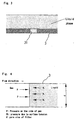
- Fig. 3 is a diagram illustrating the principle of the air trap according to the present invention.
- Fig. 4 is a diagram illustrating the principle of the air trap according to the present invention.
- Fig. 5 is a longitudinal section of an example of conventional air traps.
- Fig. 6 is a longitudinal section of another example of conventional air traps.
-
- As illustrated in Figs. 1 and 2, an air trap of the present invention comprises an air reservoir (2) to be arranged in a liquid circulation line (not illustrated in the drawing), and a hydrophilic filter (3) which permits a liquid to permeate but does not permit gas bubbles to permeate and which is arranged in the air reservoir to separate an upstream side of the liquid circulation line from the downstream side of the liquid circulation line.
- The filter (3) has a number of pores (31), which resemble capillaries, as shown in Fig. 3. If a liquid phase is separated from a gas phase by the filter (3), the pores (31) of the filter (3) are filled with the liquid and the filter (3) gets a pressure P on its one surface from the side of the gas and a pressure Ph on the opposite surface from the side of the liquid (a pressure due to surface tension), as shown in Fig. 4. In order for the gas to cause the liquid to push out of the pores (31), the gas is required to have a pressure higher than the surface tension of the liquid. A pressure equivalent to the surface tension of a liquid is generally called as a bubble point pressure. Assuming that the bubble point pressure is Pb; the pore diameter of the filter (3), d; and the surface tension of the liquid flowing through the liquid circulation line, h, the bubble point pressure Pb is related to d and h by the following equation:
- Accordingly, if the pressure P on the side of the gas phase is lower than the bubble point pressure Pb, (P < Pb), the gas in the liquid can be trapped by the filter (3). For this reason, the filter (3) used in the air trap of the present invention has pores (31) which satisfies the requirement of P < Pb, namely, the conditions as defined by the equation: P < 4h/d. For example, assuming that a pump to be used has a discharge pressure P of 10 kPa and the liquid has a surface tension of 73.21 mN/m, the diameter h of the pores should be smaller than 29.3 µm (h < 29.3 µm).
- In the air trap shown in Fig. 1, the air reservoir (2) is composed of an internal space of a container (4) arranged in the housing (1) and spaced therefrom to form a space between them. The housing (1) has at a proximal end thereof a liquid inlet (11) for the liquid from the liquid circulation line and at a distal end a liquid outlet (12) for the liquid to the liquid circulation line. The container (4) is closed at a distal end thereof but opened at a proximal end thereof to form a liquid communication with the liquid inlet (11). The container (4) is further provided in its side wall with at least one window (42) covered with the filter (3). An area of the window (42), i.e., an effective filtration area of the filter (3) is determined in consideration of a fluid resistance of the filter (3) and reduction in the filtering area caused by the trapped air, so that the liquid pressure acting on the filter, that is, the pressure on the side of the gas can not exceed the liquid pressure at the liquid inlet (11).
- As a material for forming the filter (3), there may be used cellulose, ultra-high-molecular-weight polyethylene, polyethylene, polymethylmethacrylate, polypropylene, polyvinyl chloride, polycarbonate, polytetrafuloroethylene, polyvinylidene fluoride, polyester, polyamide, metallic fiber and the like. The liquid, which is circulated through the liquid circulation line by the pump (not illustrated in the drawing), enters into the air reservoir (2) through the liquid inlet (11) of the air trap, passes through the filter (3) and flows out of the liquid outlet (12) through the outer space formed between the container (4) and the housing (1). If the gas bubbles are contained in the liquid flowing into the air reservoir (2), the bubbles are trapped by the filter and remain in the air reservoir (2). Therefore, there is no possibility for the bubbles to push out through the air trap.
- In this embodiment, the container (4) is not necessarily closed at the distal end as shown in Fig. 1. Alternatively, the container (4) may be provided at the distal end thereof with a window (42) covered with a filter (3).
- The air trap shown in Fig. 2 comprises a flat housing (5) provided with an air reservoir (6). The air reservoir (6) is constituted by an internal space of the flat housing (5), which is provided with a liquid inlet (51) for the liquid entering into the internal space from a liquid circulation line and a liquid outlet (52) for the liquid flowing out to the liquid circulation line. The inlet (51) and outlet (52) are provided oppositely from each other, vertically and axially symmetric to each other relative to the plane surface of the housing (5), respectively. The internal space of the housing (5) is partitioned by a filter (7) into two spaces, i.e., a space on a liquid inlet side and a space on a liquid outlet side. However, the liquid inlet (51) and the liquid outlet (52) are not necessarily arranged vertically and axially symmetric to each other, in so far as they are arranged oppositely from each other relative to the plane surface of the housing (5). The housing (5) having a configuration as shown in Fig. 2 may be constructed, for example, by preparing two identical flat members (5a), (5b) each having a recess (53), (54) formed in one side thereof and a cylindrical projection serving as a liquid inlet (51) or a liquid outlet (52) formed in the other side thereof, mating the two flat members (5a), (5b) together with a filter (7) placed between them so that the liquid inlet (51) and the liquid outlet (52) are located axially symmetric to each other, and then welding the flat members (5a) and (5b). In that case, the recessed portions (53) and (54) are faced each other to form a space partitioned by the filter into an air reservoir (6) and a space communicated with the liquid outlet (52).
- The depth of the recessed portion (53) forming the air reservoir (6) is determined so that the liquid in the recessed portion (53) always come into contact with the whole area of the filter (7) to avoid the dependency of the flow rate of the liquid passing through the filter (7) on the installation mode of the air trap (specifically whether the recessed portions (53), (54) are set vertically or horizontally). The depth of the recessed portion ranges, preferably from about 0.1 to about 4.0 mm and, more preferably, from 0.5 to 2.0 mm.
- There were prepared five air traps for each of the constructions shown in Fig. 2 and Fig. 6. Each air trap was set in a liquid-circulation line, which was then operated to circulate the liquid in the circulation line. After continuous operation of each circulation line for 24 hours, measurements were made on a flow rate of the liquid every one
minute 5 times. The measurements of the flow rate were carried out under the following conditions: - An inlet temperature of the liquid at the liquid inlet: 49°C
- Pore size of the filter: 5 µm
- Depth of the recessed portion (53): 1.0 mm
- Discharge pressure of the pump: 5 kPa.
-
- The results are shown in Table 1. In case of the air trap of Comparative Example 2, the circulation of the liquid was stopped after elapse of 10 days.
- As can be seen from the results shown in Table 1, the air traps according to the present invention possess significantly stable the flow rates.
Flow rate Average Initial value 60.0 59.0 61.0 59.0 61.0 60.0 Example 1 61.0 60.0 59.0 60.0 60.0 60.0 Example 2 59.0 61.0 59.0 59.0 58.0 59.2 Example 3 57.0 57.0 60.0 59.0 58.0 58.2 Initial value 61.0 61.0 58.0 57.0 56.0 58.6 Comparative Example 1 48.0 49.0 45.0 48.0 49.0 47.8 Comparative Example 2 49.0 49.0 49.0 44.0 43.0 46.8 Comparative Example 2 43.0 37.0 42.0 39.0 37.0 39.6 - As will be understood from the foregoing description, the use of the air traps according to the present invention makes it possible to stabilize the discharge rate of the pumps of the cooling systems.
Claims (4)
- An air trap for liquid circulation line, comprising an air reservoir to be arranged in a liquid circulation line, and a hydrophilic filter, which permits a liquid to permeate but does not permit bubbles to permeate and which is arranged in the air reservoir to separate an upstream side of the liquid circulation line from a downstream side of the liquid circulation line.
- An air trap according to claim 1, wherein the filter has pores which meet conditions defined by equation (1):
- An air trap according to claim 1 or 2, wherein the air reservoir is composed of an internal space of a container arranged in a housing and spaced therefrom to form a space between them, said housing being provided at a proximal end thereof with a liquid inlet for a liquid from the liquid circulation line and at a distal end thereof with a liquid outlet for the liquid flowing out to the liquid circulation line, said container being communicated with the liquid inlet at a proximal end thereof and provided with at least one window; said filter being so arranged as to cover the window of the container.
- An air trap according to claim 1 or 2, wherein the air reservoir is composed of an internal space of a flat housing, said housing being provided with a liquid inlet and a liquid outlet for a liquid entering from or flowing out to the liquid circulation line on the opposite sides of the flat housing, said internal space being partitioned by said filter into a liquid inlet side space and a liquid outlet side space.
Applications Claiming Priority (2)
| Application Number | Priority Date | Filing Date | Title |
|---|---|---|---|
| JP2000399888A JP2002191905A (en) | 2000-12-28 | 2000-12-28 | Air trap for liquid circulation circuit |
| JP2000399888 | 2000-12-28 |
Publications (2)
| Publication Number | Publication Date |
|---|---|
| EP1219333A1 true EP1219333A1 (en) | 2002-07-03 |
| EP1219333B1 EP1219333B1 (en) | 2011-10-05 |
Family
ID=18864572
Family Applications (1)
| Application Number | Title | Priority Date | Filing Date |
|---|---|---|---|
| EP01130602A Expired - Lifetime EP1219333B1 (en) | 2000-12-28 | 2001-12-21 | Air trap for liquid circulation line |
Country Status (3)
| Country | Link |
|---|---|
| US (1) | US6669762B2 (en) |
| EP (1) | EP1219333B1 (en) |
| JP (1) | JP2002191905A (en) |
Cited By (4)
| Publication number | Priority date | Publication date | Assignee | Title |
|---|---|---|---|---|
| WO2007008629A3 (en) * | 2005-07-11 | 2007-06-07 | Hewlett Packard Development Co | Separation of liquid and gas from froth |
| WO2018013073A1 (en) * | 2016-07-11 | 2018-01-18 | Hewlett-Packard Development Company, L.P. | Froth coalescing vent |
| WO2018190840A1 (en) * | 2017-04-13 | 2018-10-18 | Hewlett-Packard Development Company, L.P. | Froth coalescing device |
| WO2018190841A1 (en) * | 2017-04-13 | 2018-10-18 | Hewlett-Packard Development Company, L.P. | Froth coalescing device |
Families Citing this family (7)
| Publication number | Priority date | Publication date | Assignee | Title |
|---|---|---|---|---|
| JP2002191905A (en) * | 2000-12-28 | 2002-07-10 | Nipro Corp | Air trap for liquid circulation circuit |
| KR100777172B1 (en) * | 2004-06-07 | 2007-11-28 | 나노 퓨전 가부시키가이샤 | Electroosmotic pump system and electroosmotic pump |
| JP2006275016A (en) * | 2005-03-30 | 2006-10-12 | Science Solutions International Laboratory Inc | Liquid transport device and liquid transport system |
| EP1873532A1 (en) * | 2005-03-30 | 2008-01-02 | NANO Fusion Technologies, Inc. | Electroosmosis pump and liquid feeding device |
| DE102009045403B4 (en) * | 2009-10-06 | 2022-08-04 | Fraunhofer-Gesellschaft zur Förderung der angewandten Forschung e.V. | Device for separating gas and liquid and uses thereof |
| US10179213B2 (en) * | 2015-05-27 | 2019-01-15 | Vital Signs, Inc. | Apparatus and methods for intravenous gas elimination |
| EP4140529A4 (en) * | 2020-04-23 | 2024-05-29 | Otsuka Techno Corporation | URINARY CATHETER CAP |
Citations (5)
| Publication number | Priority date | Publication date | Assignee | Title |
|---|---|---|---|---|
| DE1816972A1 (en) * | 1967-12-26 | 1969-07-24 | Baxter Laboratories Inc | Filter for a device for parenteral inflow of fluids |
| US4004587A (en) * | 1975-06-13 | 1977-01-25 | Baxter Travenol Laboratories, Inc. | Parenteral liquid administration set with non-air blocking filter |
| US4031891A (en) * | 1975-11-03 | 1977-06-28 | Baxter Travenol Laboratories, Inc. | Air eliminating filter |
| DE4219966A1 (en) * | 1991-07-26 | 1993-01-28 | Sartorius Gmbh | Rotationally symmetrical filter with hydrophilic and hydrophobic filter media - used for filtering and degassing liquids e.g. sterile filtration of aq. solns. and cell culture media |
| JPH0994402A (en) * | 1995-10-03 | 1997-04-08 | Nec Corp | Bubble removing method |
Family Cites Families (21)
| Publication number | Priority date | Publication date | Assignee | Title |
|---|---|---|---|---|
| US3273319A (en) * | 1963-06-05 | 1966-09-20 | Continental Oil Co | Device for removing entrained gases from viscous liquids |
| US3631654A (en) * | 1968-10-03 | 1972-01-04 | Pall Corp | Gas purge device |
| US4302223A (en) * | 1969-03-26 | 1981-11-24 | The United States Of America As Represented By The Administrator Of The National Aeronautics And Space Administration | Air removal device |
| US4341538A (en) * | 1978-08-18 | 1982-07-27 | Gelman Instrument Company | Intravenous filter |
| US4319996A (en) * | 1980-11-10 | 1982-03-16 | Gelman Sciences, Inc. | Filter with initially flat membrane and curved membrane support |
| US4336036A (en) * | 1981-01-08 | 1982-06-22 | Amf Incorporated | Filter and method of making same |
| JPS6344083Y2 (en) * | 1981-04-21 | 1988-11-16 | ||
| US4459139A (en) * | 1981-09-14 | 1984-07-10 | Gelman Sciences Inc. | Disposable filter device and liquid aspirating system incorporating same |
| DE3304951A1 (en) * | 1983-02-12 | 1984-08-16 | Akzo Gmbh, 5600 Wuppertal | DEVICE FOR FILTERING A LIQUID |
| US4615694A (en) * | 1985-02-15 | 1986-10-07 | Burron Medical Inc. | Vented cone filter |
| DE3624363C2 (en) * | 1986-07-18 | 1995-06-08 | Akzo Gmbh | Device for separating gas bubbles from infusion liquids or liquids from the human body |
| JPH0657252B2 (en) * | 1988-08-26 | 1994-08-03 | テルモ株式会社 | Blood reservoir |
| US4976754A (en) * | 1989-12-05 | 1990-12-11 | Grumman Aerospace Corporation | Liquid line non-condensible gas trap |
| US5439587A (en) * | 1993-07-27 | 1995-08-08 | Millipore Corporation | Self priming filter apparatus |
| US5472605A (en) * | 1994-03-10 | 1995-12-05 | Hemasure, Inc. | Filtration device useable for removal of leukocytes and other blood components |
| DE19626212C2 (en) * | 1996-06-29 | 1998-04-23 | Luk Fahrzeug Hydraulik | Oil suction filter |
| US5989318A (en) * | 1998-05-19 | 1999-11-23 | International Fuel Cells Corporation | Apparatus for separating water from a two-phase stream |
| US6402821B1 (en) * | 1998-08-18 | 2002-06-11 | Tokyo Electron Limited | Filter unit and solution treatment unit |
| US6342092B1 (en) * | 1999-10-07 | 2002-01-29 | General Dynamics Ots (Aerospace), Inc. | Apparatus to separate gas from a liquid flow |
| AT3433U3 (en) * | 1999-12-30 | 2001-04-25 | Avl List Gmbh | SYSTEM FOR CONDUCTING LIQUID MEDIA AND FILTER DEVICE FOR USE IN THIS SYSTEM |
| JP2002191905A (en) * | 2000-12-28 | 2002-07-10 | Nipro Corp | Air trap for liquid circulation circuit |
-
2000
- 2000-12-28 JP JP2000399888A patent/JP2002191905A/en active Pending
-
2001
- 2001-12-21 EP EP01130602A patent/EP1219333B1/en not_active Expired - Lifetime
- 2001-12-21 US US10/024,180 patent/US6669762B2/en not_active Expired - Fee Related
Patent Citations (5)
| Publication number | Priority date | Publication date | Assignee | Title |
|---|---|---|---|---|
| DE1816972A1 (en) * | 1967-12-26 | 1969-07-24 | Baxter Laboratories Inc | Filter for a device for parenteral inflow of fluids |
| US4004587A (en) * | 1975-06-13 | 1977-01-25 | Baxter Travenol Laboratories, Inc. | Parenteral liquid administration set with non-air blocking filter |
| US4031891A (en) * | 1975-11-03 | 1977-06-28 | Baxter Travenol Laboratories, Inc. | Air eliminating filter |
| DE4219966A1 (en) * | 1991-07-26 | 1993-01-28 | Sartorius Gmbh | Rotationally symmetrical filter with hydrophilic and hydrophobic filter media - used for filtering and degassing liquids e.g. sterile filtration of aq. solns. and cell culture media |
| JPH0994402A (en) * | 1995-10-03 | 1997-04-08 | Nec Corp | Bubble removing method |
Non-Patent Citations (2)
| Title |
|---|
| C.DICKENSON: "Filters and Filtration Handbook", 1997, ELSEVIER ADVANCED TECHNOLOGY, OXFORD,GB, XP002193660 * |
| PATENT ABSTRACTS OF JAPAN vol. 1997, no. 08 29 August 1997 (1997-08-29) * |
Cited By (9)
| Publication number | Priority date | Publication date | Assignee | Title |
|---|---|---|---|---|
| WO2007008629A3 (en) * | 2005-07-11 | 2007-06-07 | Hewlett Packard Development Co | Separation of liquid and gas from froth |
| US7449051B2 (en) * | 2005-07-11 | 2008-11-11 | Hewlett-Packard Development Company, L.P. | Separation of liquid and gas from froth |
| CN101222963B (en) * | 2005-07-11 | 2010-12-22 | 惠普开发有限公司 | Separator for separating liquid and gas from foam and method for extracting liquid from foam |
| WO2018013073A1 (en) * | 2016-07-11 | 2018-01-18 | Hewlett-Packard Development Company, L.P. | Froth coalescing vent |
| US11117073B2 (en) | 2016-07-11 | 2021-09-14 | Hewlett-Packard Development Company, L.P. | Froth coalescing vent |
| WO2018190840A1 (en) * | 2017-04-13 | 2018-10-18 | Hewlett-Packard Development Company, L.P. | Froth coalescing device |
| WO2018190841A1 (en) * | 2017-04-13 | 2018-10-18 | Hewlett-Packard Development Company, L.P. | Froth coalescing device |
| US11214074B2 (en) | 2017-04-13 | 2022-01-04 | Hewlett-Packard Development Company, L.P. | Froth coalescing device |
| US11407230B2 (en) | 2017-04-13 | 2022-08-09 | Hewlett-Packard Development Company, L.P. | Froth coalescing device |
Also Published As
| Publication number | Publication date |
|---|---|
| EP1219333B1 (en) | 2011-10-05 |
| JP2002191905A (en) | 2002-07-10 |
| US6669762B2 (en) | 2003-12-30 |
| US20020121195A1 (en) | 2002-09-05 |
Similar Documents
| Publication | Publication Date | Title |
|---|---|---|
| US6669762B2 (en) | Air trap for liquid circulation line | |
| US10619939B2 (en) | Intermittent thermosyphon | |
| US6010633A (en) | Method of preventing air from becoming entrapped within a filtration device | |
| EP0378681A1 (en) | Blood storage tank | |
| BRPI0402740B1 (en) | Cartridge for a water tank of a coffee maker | |
| CA2601128A1 (en) | Infusion fluid heat exchanger and cartridge | |
| EP1381438B1 (en) | Biological fluid filter | |
| CN109341147A (en) | Heat exchanger and air conditioner with same | |
| EP0393186B1 (en) | Blood storage tank | |
| US20150014233A1 (en) | Carafe filter with air lock prevention feature | |
| JP2002191905A5 (en) | ||
| EP0355785B1 (en) | Blood storage container | |
| CA1286945C (en) | Device for ventilating a closed conduit system | |
| KR101838993B1 (en) | Oil-water Separator | |
| JPH037391B2 (en) | ||
| US5268298A (en) | System for delivering oxygen to a cell culture medium | |
| CN209147502U (en) | Heat exchanger and air conditioner with same | |
| JP3092856B2 (en) | Blood reservoir | |
| US11214074B2 (en) | Froth coalescing device | |
| CN111692073B (en) | Pump components and heat exchange systems | |
| JPH05198869A (en) | Laser oscillator cooling device | |
| JPH05146508A (en) | Heat exchanger and blood reservoir | |
| KR910005410B1 (en) | Extracorporeal blood circulating apparatus | |
| JPH0688604A (en) | Deaerator | |
| JPH04336075A (en) | Blood storage tank |
Legal Events
| Date | Code | Title | Description |
|---|---|---|---|
| PUAI | Public reference made under article 153(3) epc to a published international application that has entered the european phase |
Free format text: ORIGINAL CODE: 0009012 |
|
| AK | Designated contracting states |
Kind code of ref document: A1 Designated state(s): AT BE CH CY DE DK ES FI FR GB GR IE IT LI LU MC NL PT SE TR |
|
| AX | Request for extension of the european patent |
Free format text: AL;LT;LV;MK;RO;SI |
|
| 17P | Request for examination filed |
Effective date: 20020807 |
|
| AKX | Designation fees paid |
Designated state(s): DE FR GB IT |
|
| GRAP | Despatch of communication of intention to grant a patent |
Free format text: ORIGINAL CODE: EPIDOSNIGR1 |
|
| GRAS | Grant fee paid |
Free format text: ORIGINAL CODE: EPIDOSNIGR3 |
|
| GRAA | (expected) grant |
Free format text: ORIGINAL CODE: 0009210 |
|
| RIN1 | Information on inventor provided before grant (corrected) |
Inventor name: HIRAYAMA, TOSHIKAZU Inventor name: UENO, DAISUKE |
|
| AK | Designated contracting states |
Kind code of ref document: B1 Designated state(s): DE FR GB IT |
|
| REG | Reference to a national code |
Ref country code: GB Ref legal event code: FG4D |
|
| REG | Reference to a national code |
Ref country code: DE Ref legal event code: R096 Ref document number: 60145407 Country of ref document: DE Effective date: 20111124 |
|
| PLBE | No opposition filed within time limit |
Free format text: ORIGINAL CODE: 0009261 |
|
| STAA | Information on the status of an ep patent application or granted ep patent |
Free format text: STATUS: NO OPPOSITION FILED WITHIN TIME LIMIT |
|
| 26N | No opposition filed |
Effective date: 20120706 |
|
| REG | Reference to a national code |
Ref country code: DE Ref legal event code: R097 Ref document number: 60145407 Country of ref document: DE Effective date: 20120706 |
|
| PGFP | Annual fee paid to national office [announced via postgrant information from national office to epo] |
Ref country code: GB Payment date: 20141219 Year of fee payment: 14 Ref country code: DE Payment date: 20141211 Year of fee payment: 14 |
|
| PGFP | Annual fee paid to national office [announced via postgrant information from national office to epo] |
Ref country code: FR Payment date: 20141219 Year of fee payment: 14 |
|
| PGFP | Annual fee paid to national office [announced via postgrant information from national office to epo] |
Ref country code: IT Payment date: 20141222 Year of fee payment: 14 |
|
| REG | Reference to a national code |
Ref country code: DE Ref legal event code: R119 Ref document number: 60145407 Country of ref document: DE |
|
| GBPC | Gb: european patent ceased through non-payment of renewal fee |
Effective date: 20151221 |
|
| REG | Reference to a national code |
Ref country code: FR Ref legal event code: ST Effective date: 20160831 |
|
| PG25 | Lapsed in a contracting state [announced via postgrant information from national office to epo] |
Ref country code: DE Free format text: LAPSE BECAUSE OF NON-PAYMENT OF DUE FEES Effective date: 20160701 Ref country code: GB Free format text: LAPSE BECAUSE OF NON-PAYMENT OF DUE FEES Effective date: 20151221 |
|
| PG25 | Lapsed in a contracting state [announced via postgrant information from national office to epo] |
Ref country code: FR Free format text: LAPSE BECAUSE OF NON-PAYMENT OF DUE FEES Effective date: 20151231 |
|
| PG25 | Lapsed in a contracting state [announced via postgrant information from national office to epo] |
Ref country code: IT Free format text: LAPSE BECAUSE OF NON-PAYMENT OF DUE FEES Effective date: 20151221 |