EP1218971B1 - Sealant-filled electrical connector and method for forming the same - Google Patents
Sealant-filled electrical connector and method for forming the same Download PDFInfo
- Publication number
- EP1218971B1 EP1218971B1 EP00950280A EP00950280A EP1218971B1 EP 1218971 B1 EP1218971 B1 EP 1218971B1 EP 00950280 A EP00950280 A EP 00950280A EP 00950280 A EP00950280 A EP 00950280A EP 1218971 B1 EP1218971 B1 EP 1218971B1
- Authority
- EP
- European Patent Office
- Prior art keywords
- connector assembly
- sealant
- socket
- connector
- plug
- Prior art date
- Legal status (The legal status is an assumption and is not a legal conclusion. Google has not performed a legal analysis and makes no representation as to the accuracy of the status listed.)
- Expired - Lifetime
Links
Images


Classifications
-
- H—ELECTRICITY
- H01—ELECTRIC ELEMENTS
- H01R—ELECTRICALLY-CONDUCTIVE CONNECTIONS; STRUCTURAL ASSOCIATIONS OF A PLURALITY OF MUTUALLY-INSULATED ELECTRICAL CONNECTING ELEMENTS; COUPLING DEVICES; CURRENT COLLECTORS
- H01R13/00—Details of coupling devices of the kinds covered by groups H01R12/70 or H01R24/00 - H01R33/00
- H01R13/46—Bases; Cases
- H01R13/52—Dustproof, splashproof, drip-proof, waterproof, or flameproof cases
- H01R13/5216—Dustproof, splashproof, drip-proof, waterproof, or flameproof cases characterised by the sealing material, e.g. gels or resins
-
- H—ELECTRICITY
- H01—ELECTRIC ELEMENTS
- H01R—ELECTRICALLY-CONDUCTIVE CONNECTIONS; STRUCTURAL ASSOCIATIONS OF A PLURALITY OF MUTUALLY-INSULATED ELECTRICAL CONNECTING ELEMENTS; COUPLING DEVICES; CURRENT COLLECTORS
- H01R24/00—Two-part coupling devices, or either of their cooperating parts, characterised by their overall structure
- H01R24/60—Contacts spaced along planar side wall transverse to longitudinal axis of engagement
- H01R24/62—Sliding engagements with one side only, e.g. modular jack coupling devices
-
- Y—GENERAL TAGGING OF NEW TECHNOLOGICAL DEVELOPMENTS; GENERAL TAGGING OF CROSS-SECTIONAL TECHNOLOGIES SPANNING OVER SEVERAL SECTIONS OF THE IPC; TECHNICAL SUBJECTS COVERED BY FORMER USPC CROSS-REFERENCE ART COLLECTIONS [XRACs] AND DIGESTS
- Y10—TECHNICAL SUBJECTS COVERED BY FORMER USPC
- Y10S—TECHNICAL SUBJECTS COVERED BY FORMER USPC CROSS-REFERENCE ART COLLECTIONS [XRACs] AND DIGESTS
- Y10S439/00—Electrical connectors
- Y10S439/933—Special insulation
- Y10S439/936—Potting material or coating, e.g. grease, insulative coating, sealant or, adhesive
Definitions
- the present invention relates to the field of electrical connectors, especially for telephone and data communication equipment, and, more particularly, to environmentally protected modular electrical connectors.
- Telephone line connections at subscriber locations are commonly made with the RJ-type of plug and socket connector such as an RJ-11 or RJ-45.
- These connectors are exemplary of electrical connections susceptible to failure from oxidation, corrosion, humidity, salt, and the like, especially in the presence of a live voltage on the conductors within the connector.
- RJ-type sockets are likewise subject to moisture contamination and corrosion, as well as being subject to dust buildup. In hot, humid environments, such as in Florida and along the Gulf Coast of Texas, failure can occur within several months of installation. Servicing these failures is costly for the consumer or the telephone company.
- RJ-type connector of the type well known to those of skill in the art, or other such connector, at an external location at a subscriber facility, such as a junction box leading to a house, or a remote terminal of the type described above.
- Access may be provided by installing a female RJ-type socket which is normally connected to a male RJ-type plug.
- the tip and ring wires (among other wires in some cases) lead from the female RJ-type socket, and connect to tip and ring connections in the male RJ-type plug, thereafter leading into the subscriber facility.
- the plug When it is desired to connect test equipment to the RJ-type female socket, the plug may be removed, and another male RJ-type may be inserted into the female socket, thereby providing tip and ring connections for the test equipment. Even though the equipment may be contained in a protective housing, such arrangements are sometimes subject to much of the same moisture/corrosion degradation.
- RJ-type connectors are employed to connect networked computer stations for data communication.
- RJ-type connectors are used in components such as servers situated in closets. The temperatures and humidities present in the closets may vary widely and tend to degrade the connections or short circuit adjacent contacts.
- Applicant has designed plug and socket type sealant-filled electrical connectors to overcome or reduce the above-described problems. See, e.g., the disclosures of U.S. Patent Nos. 5,562,491 and 5,601,460, each to Shimirak et al.
- EP-A-0,874, 418 (D1) discloses a connector according to the connector of claim 1 for connecting electrical wires.
- the connector comprises a housing or enclosure that surrounds contacts while making a connection to a plug.
- the housing is filled with a colloidal gel environmental protection material that includes particles that will absorb electromagnetic radiation.
- the housing includes a number of spring contacts comprising output terminals of conductors that are connected to a plurality of input terminals which are connected to twisted pairs of communication wire, such as telephone or data lines.
- the interior of the housing is filled to surround the conductors, spring contacts, and the input terminals with the colloidal gel.
- the housing has a bottom wall and a right side and end walls to form an enclosure. Part of the housing is broken away after the gel has set and a load bar for carrying wires is put into place to connect the wires to the input terminals.
- the colloidal gel is squeezed around the input terminals and the wire connections.
- the present invention is generally directed to improved environmentally protected electrical connectors of the type having a socket adapted to receive a plug, and methods for forming and using the same.
- the inventive aspects of the present invention may be applied to RJ-type sockets, for example.
- sealant-filled connector as claimed in Claim 1.
- the environmental sealant is preferably a gel.
- the gel-filled connector assembly 100 includes a socket 102.
- a sealant 110 is disposed within the socket 102 to protect electrically conductive components thereof from dust and moisture and other corrosives.
- the sealant 110 is preferably, and will hereinafter be referred to as, a gel. However, other types of sealants may be used as discussed below.
- the gel-filled connector assembly 100 is shown with an associated cap 170 mounted thereon.
- the gel-filled connector assembly 100 is shown with an associated device connector 180 connected thereto.
- the connector 180 includes a load bar or wire terminating cap 181 through which four wires 182 are inserted.
- the load bar 181 includes partition walls 188 between the respective wires 182 adjacent the ends 182A of the wires 182.
- the partition walls 188 define slots 188A within which the end portions of the wires are received as shown.
- the load bar 181, and thereby the wires 182 are secured to the gel-filled connector assembly 100 by a connecting leg 186. It will be appreciated that more than four wires and connectors other than the connector 180 as shown and described herein may be used.
- Figures 1-4 show the socket 102 without the gel 110 for clarity.
- Figure 7 shows a base member 120 forming a part of the socket 102, also shown without the gel 110.
- the gel-filled connector assembly 100 is adapted to receive and electrically connect with a suitable male plug (not shown), for example, an RJ-type plug.
- RJ-type plugs are well known to those of ordinary skill in the art.
- the socket 102 includes the base member 120 and an insert member 150.
- the base member 120 has a rear portion 122 and front portion 124.
- the insert member 150 has a rear portion 152 and a front portion 154.
- the base member 120 and the insert member 150 are securely fitted together as will be better appreciated from the description that follows. It will be appreciated, however, that the inventive aspects of the present invention may be employed in sockets configured differently than described herein.
- the base member 120 is preferably integrally molded from a suitable plastic such as a polycarbonate, polyphenylene oxide, or polycarbonate ABS alloy.
- the base member 120 includes a plug cavity 126 adapted to receive the RJ or other type plug (not shown).
- a rear partition wall or tine block 125 forms the back wall of the cavity 126.
- a series of guide walls 128 forming a part of the wall 125 form a "comb" defining a series of tine slots 128A.
- the lower edge 125A of the rear wall 125 is positioned to provide a passageway 130 in the base member 120.
- the passageway 130 defines a passageway 130A in the socket 102.
- the cavity 126 has interior side wall surfaces 140.
- the interior surfaces 140 are textured to increase their overall surface areas.
- the forwardly facing surface 125B of the rear wall 125 and/or the upper surface 157 of the insert member 150 in the cavity 126 may also be textured.
- the texturing may be formed by abrading the walls 140 and other surfaces or molding the walls 140 and other surfaces to make the surfaces rough.
- the texturing increases the surface areas of the surfaces (as compared to smooth surfaces) by at least 10% and, more preferably, by between about 20% and 66%.
- the textured surfaces may be roughened by sandblasting the mold from which they are formed to provide a particulate lay to the surfaces.
- the rough surfaces 125B, 140 have a rating of at least N12 per ISO 1320:1992 or a roughness average of at least 2000 micro-inches. It is also contemplated that the textured surfaces 125B, 140 may have a random or regular raised pattern, as discussed in greater detail below.
- the increased surface area of the textured surface is intended to provide greater contact area between the interior surfaces 140 and the gel 110 which enhances the adhesion of the gel 110 to the socket 102.
- This enhanced adhesion reduces the tendency of the gel 110 to be removed from the socket 102 with a plug when the plug is inserted and removed.
- the enhanced adhesion also helps to reduce inward displacement of the gel when the plug is inserted, thereby helping to ensure that the tines remain fully covered when the plug is inserted.
- the textured surface preferably engages the gel 110 to provide mechanical resistance to removal of the gel 110 from the socket 102.
- the base member 120 further includes a cavity or reservoir 136 formed therein.
- the reservoir 136 extends through portions of the rear portion 122 and the front portion 124 including extending beneath the rear wall 125.
- Apertures 122A and 122B are positioned in the base member 120. Also, a recess 122C is positioned in the base member 120. Preferably, the apertures 122A, 122B, 122C are formed in the base member such as by molding.
- the insert member 150 is preferably integrally molded of a suitable plastic such as a polycarbonate, polyphenylene oxide, or polycarbonate ABS alloy. Apertures 152A and 152B are positioned therein. A projection 152C extends from the lower surface of the insert member 150. Also, as discussed below in more detail, a cavity or trough 132 is positioned in the upper surface of the insert member 150. A series of spaced apart guide walls 156 ( Figure 1) define a series of tine slots 134 therebetween.
- a plurality of side by side electrical leads 160 extend lengthwise along the insert member 150.
- Each lead 160 preferably includes an insulation displacement connector (hereinafter, "IDC") 162, a tine 164 and a connecting portion 166.
- IDC insulation displacement connector
- each lead 160 is formed of a continuous and integral strip of electrically conductive metal.
- the IDC 162 projects above the upper surface of and extends through the thickness of the insert member 150
- the connecting portion 166 extends along the bottom surface of the insert member 150
- the tine 164 is positioned in a respective one of the slots 128 and a respective one of the slots 134.
- the tines are spring loaded, i.e., biased upwardly against the rear wall 125.
- leads 160 may be provided.
- a second row of IDCs 162 staggered with the first row of IDCs 162 and allowing for an increased number of tines 164 (e.g., eight tines, as may be required in a data or telephone jack).
- tines 164 e.g., eight tines, as may be required in a data or telephone jack.
- the insert member 150 is mounted in the base member 120 by sliding the front end 154 through the passageway 130. As the insert member 150 is inserted, the tines 164 are received in, guided by and retained in spaced apart relation by the walls 128. When the insert member 150 is fully inserted, the projection 152C interlocks with the recess 122C.
- the members 120 and 150 may be bonded, welded, mechanically fastened or otherwise further joined.
- the upper surface of the insert member 150 and the lower edge of the rear wall 125 define a passageway 130A in the passageway 130.
- the gel material 110 may be installed. It will be appreciated that methods of installing the gel other than as described hereinbelow may be employed.
- the cap 170 is mounted on the socket 102 such that the legs 172 snap fit over the socket 102 and a prescribed portion 174 of the cap receives the row of IDCs 162.
- the socket 102 is placed such that the front portion 124 is oriented vertically over the rear portion 122.
- An uncured gel material is then poured into the socket 102 through the cavity 126.
- the socket 102 is configured such that each of the various cavities 126, 132, 136 defined by the base member 120 and the insert member 150 are filled and the exposed portions of the leads 160 are covered.
- the uncured gel material flows through and into the slots 128A and the passageway 130A to fill the trough 132 and to cover the IDCs 162 as shown.
- the passageway 130A provides a substantial passageway for flow of the gel material allowing for fast and consistent flow of the uncured gel material from the cavity 126 to the rear portion of the socket 102. Flow of the gel material into these areas is facilitated by an air vent 176 formed in the cap 170. Additionally, gel material flows through the slots 134 to fill the reservoir 136. Once the cavities 126, 132, 136 and the passageway 130A have been filled, the socket 102 is preferably tilted such that the tines 164 are oriented substantially parallel with the horizontal plane. The gel material is then cured by suitable means to form the gel 110. In the preferred embodiment, as shown, the gel covers the tines 164 while leaving an unfilled portion of the cavity 126 to accept a plug.
- the environmental sealant 110 is preferably a hydrophobic dielectric designed to exclude moisture and insulate the wires and contacts. Gels are preferred, with the most preferred being silicone gels. The preferred gels have a cohesiveness greater than their tack (adhesion to other surfaces), so that when the plug is removed from the socket 126, the gel 110 will release the plug rather than separating from the main body of gel within the socket. The gel requires a sufficient adhesion, however, so that it will form an acceptable seal around the contacts, wires, and other portions of the apparatus in need of environmental protection.
- the sealant should have a hardness sufficient to provide lasting protection against environmental contaminants.
- the sealant should be soft enough to be displaced by the plug and conform to the shape of the socket assembly and adequately seal it while allowing an acceptable electrical connection between the socket and the plug.
- the gel's hardness may also impact a customer preference: an audible "click" when the RJ-type plug is fully inserted and latches into the RJ-type socket. If the sealant is too stiff, this click may be muted.
- sealants are available for this use, including, for example, elastic hot melt materials, greases, and flexible epoxies.
- the sealant is a dielectric gel such as an oil or plasticizer extended aliphatic urethane gels, urea gels, silicone gels, and thermoplastic gels like styrene-ethylene-butylene-styrene or styrene-ethylene-propylene-styrene, or other soft gels having the required properties below whether or not oil or plasticizer extended, including those disclosed in U.S. Pat. Nos.
- Preferred gels used in conjunction with the present invention include those having a cone penetration value from about 50 to about 350 ⁇ 10 -1 mm, more preferably about 100 to about 300 ⁇ 10 -1 mm, and most preferably about 100 to about 250 ⁇ 10 -1 mm. Preferred gels also have an ultimate elongation of at least about 100%, more preferably at least about 500% to 1000%, and most preferably greater than 1400%.
- another measurement for hardness is Voland hardness.
- the Voland hardness is generally measured on a Voland texture analyzer apparatus. Voland hardnesses from about 10 grams to at least about 50 grams are acceptable for the gel, with preferred gels having Voland hardnesses from about 20 to about 40 grams.
- the preferred environmental sealant is a silicone gel having a Voland hardness of about 29 ⁇ 6 grams, a stress relaxation of about 28 ⁇ 10%, and a tack of about 17 ⁇ 5 grams.
- the cavities of the RJ-type plug are also preferably substantially completely filled with the gel 110.
- the gel 110 is distributed through the socket 102 as shown in Figure 5, and with reference to Figure 4.
- a portion 110A of the gel fills a substantial portion of the cavity 126 and covers the tines 164.
- a portion 110B of the gel fills the slots 128A and a portion 110C of the gel fills the passageway 130A.
- a portion 110D of the gel fills the space between the rear wall 125 and the IDCs 162.
- a portion 110E of the gel surrounds and extends between the IDCs 162.
- a portion 110F of the gel fills the trough 132.
- a portion 110G of the gel fills the slots 134.
- a portion 110H of the gel fills the reservoir 136.
- each IDC 162 displaces the insulation of a respective one of the wires 182 and makes electrical contact with the wire conductor.
- the IDCs 162, the tines 164, and the connecting portions 166 are fully encapsulated or "sealed" in the socket 102 and the gel 110 such that they are protected from moisture or contaminates from the environment.
- the gel portion 110H in the reservoir 136 covers the connecting portions 166. In this way, the gel portion 110H also serves to electrically isolate the respective connecting portions 166 from one another.
- the gel portion 110H also serves to protect the connecting portions 166 from corrosion and the like.
- the wire ends 182A are received in the gel portion 110F in the trough 132.
- the gel portion 110F serves to electrically isolate the wire ends 182A from one another and to protect the wire ends from contamination.
- part of the gel portion 110D fills some or all of the slots 188A of the load bar 181.
- the apertures 122A, 152A receive the connecting leg 186 of the connector 180.
- the apertures 122B, 152B ( Figure 3) receive locating projections (not shown) of the connector 180. It will be appreciated that other means for attaching the connector 180 to the socket 102 may be provided.
- the textured surfaces of the plug cavity may have a raised pattern.
- a preferred raised pattern is illustrated in Figure 8 which shows an enlarged, fragmentary view of a side wall 240 of an alternative base member 220 otherwise corresponding to the base member 120 and which may be used in place thereof.
- the side wall 240 corresponds to the side wall 140 except that the side wall 240 includes a plurality of raised protrusions or bumps 242 extending into the plug cavity 226.
- the bumps 242 may be arranged in a random, regular or semi-regular pattern.
- the bumps 242 are preferably molded into the base member 220, and a reverse pattern may be machined or electric discharge machined into the mold.
- Bumps may also be formed on the forwardly facing surface of the rear wall (not shown) and/or the upper surface of the portion of the insert member (not shown) in the cavity 226.
- the bumps 242 serve to increase the surface area for engagement with the gel (not shown) as well as to mechanically retain the gel.
- the bumps are substantially half-spheres having a radius of between about 0.005 inch and 0.030 inch.
- the bumps 242 are spaced apart. According to a further embodiment (not shown), the bumps are intertangential such that the bumps are arranged as densely as feasible. The bumps are otherwise formed as described with regard to the base member 220.
- a base member 320 according to a further embodiment is shown therein.
- the base member 320 may be used in place of the base member 120 as described above. Except as discussed below, the base member 320 is preferably formed in the same configuration, in the same manner, and from the same materials as the base member 120.
- a plug cavity 326 is formed in the front portion 324 of the base member 320.
- the interior surfaces 340 of the plug cavity 326 of the base member 320 include a plurality of integrally molded ribs 342 extending inwardly therefrom. The ribs 342 serve to increase the surface area for engagement with the gel (not shown) in similar manner to the raised pattern described above with regard to the base member 220.
- Ribs may also be formed on the forwardly facing surface 325A of the rear wall 325 and/or the exposed surface of the insert member (not shown) in the cavity 326.
- the ribs may be disposed at angles other than as shown in the illustrated embodiment.
- Raised patterns of configurations other than those described above may be employed.
- the raised patterns may be pyramids.
- a base member 420 according to a further embodiment of the present invention is shown therein.
- the base member 420 may be used in place of the base member 120 as described above.
- a plug cavity 426 is formed in the front portion 424 of the base member 420.
- the interior surfaces 440 of the cavity 426 are covered by molded inserts 442.
- the molded inserts 442 are formed of a material exhibiting greater adhesion with the gel (not shown) than the material from which the base member 420 is formed.
- the mold inserts 442 are formed from elastomeric material. More preferably, the mold inserts 442 are formed from silicone rubber, and, more preferably, from addition-cured silicone rubber.
- the mold inserts 442 are secured to the walls of the base member 420 in the illustrated embodiment by respective T-shaped projections 442A and nibs 442B which are received in complementary shaped slots 440A and 440B, respectively.
- Alternative means for securing the molded inserts 442 may be used as an alternative to or in addition to the elements 442A, 442B, 440A, and 440B.
- the molded inserts 442 may be bonded or adhered to the interior surfaces 440.
- the slots 440A, 440B are formed during the molding of the base portion 420 and the molded inserts 442 are formed and mounted in the cavity 426 by injection molding.
- the inserts 442 enhance the mechanical adhesion between the gel and the base member and may also form a chemical bond with the gel.
- the inserts 442 may also include integrally molded bumps, ribs or other raised patterns or other texturing as described above to engage the gel in the cavity 426 .
Abstract
Description
- The present invention relates to the field of electrical connectors, especially for telephone and data communication equipment, and, more particularly, to environmentally protected modular electrical connectors.
- Telephone line connections at subscriber locations are commonly made with the RJ-type of plug and socket connector such as an RJ-11 or RJ-45. These connectors are exemplary of electrical connections susceptible to failure from oxidation, corrosion, humidity, salt, and the like, especially in the presence of a live voltage on the conductors within the connector.
- For example, it is sometimes difficult to establish and maintain an adequate environmental seal in a removable male RJ-type plug, particularly when wires lead from the male RJ-type plug. Accordingly, moisture and other environmental contaminants are allowed to enter such plugs, sometimes resulting in corrosion and/or failure of the connection of the tip and ring connections in the socket/plug combination. RJ-type sockets are likewise subject to moisture contamination and corrosion, as well as being subject to dust buildup. In hot, humid environments, such as in Florida and along the Gulf Coast of Texas, failure can occur within several months of installation. Servicing these failures is costly for the consumer or the telephone company.
- Problems may also arise in connection with test ports for customer telecommunications equipment such as remote terminals at customer facilities and the like. It is often desirable to provide an RJ-type connector of the type well known to those of skill in the art, or other such connector, at an external location at a subscriber facility, such as a junction box leading to a house, or a remote terminal of the type described above. Access may be provided by installing a female RJ-type socket which is normally connected to a male RJ-type plug. The tip and ring wires (among other wires in some cases) lead from the female RJ-type socket, and connect to tip and ring connections in the male RJ-type plug, thereafter leading into the subscriber facility. When it is desired to connect test equipment to the RJ-type female socket, the plug may be removed, and another male RJ-type may be inserted into the female socket, thereby providing tip and ring connections for the test equipment. Even though the equipment may be contained in a protective housing, such arrangements are sometimes subject to much of the same moisture/corrosion degradation.
- A similar problem may be experienced where RJ-type connectors are employed to connect networked computer stations for data communication. Commonly, such RJ-type connectors are used in components such as servers situated in closets. The temperatures and humidities present in the closets may vary widely and tend to degrade the connections or short circuit adjacent contacts.
- Applicant has designed plug and socket type sealant-filled electrical connectors to overcome or reduce the above-described problems. See, e.g., the disclosures of
U.S. Patent Nos. 5,562,491 and5,601,460, each to Shimirak et al. - One problem experienced with plug and socket type sealant-filled electrical connectors, including gel-filled connectors, is a tendency for the sealant material to be removed with the plug when the plug is inserted into the socket and removed. In order to improve the adhesion of the sealant to the socket as compared to the adhesion to the plug, cleaners or primer coats have been applied to the sealant contacting surfaces of the socket. However, these techniques frequently do not provide the degree of adhesion desired.
-
EP-A-0,874, 418 (D1) discloses a connector according to the connector ofclaim 1 for connecting electrical wires. The connector comprises a housing or enclosure that surrounds contacts while making a connection to a plug. The housing is filled with a colloidal gel environmental protection material that includes particles that will absorb electromagnetic radiation. The housing includes a number of spring contacts comprising output terminals of conductors that are connected to a plurality of input terminals which are connected to twisted pairs of communication wire, such as telephone or data lines. The interior of the housing is filled to surround the conductors, spring contacts, and the input terminals with the colloidal gel. The housing has a bottom wall and a right side and end walls to form an enclosure. Part of the housing is broken away after the gel has set and a load bar for carrying wires is put into place to connect the wires to the input terminals. The colloidal gel is squeezed around the input terminals and the wire connections. - There is a need for an improved design and method for installing an environmental sealant. For example, it is often desirable to provide an environmental sealant, including a gel sealant, in connectors not originally designed to employ a sealant. It has been found that such connectors may not allow for efficient and cost-effective installation of sealant.
- The present invention is generally directed to improved environmentally protected electrical connectors of the type having a socket adapted to receive a plug, and methods for forming and using the same. The inventive aspects of the present invention may be applied to RJ-type sockets, for example.
- According to an aspect of the present invention there is provided a sealant-filled connector, as claimed in
Claim 1. - According to another aspect of the present invention there is provided a method of forming a sealant-filled connector assembly, as claimed in Claim 23.
- In each of the foregoing connector assemblies and methods, the environmental sealant is preferably a gel.
- The present invention is explained in greater detail with reference to the preferred embodiments in the drawings herein and the specification set forth below.
-
- Figure 1 is a front perspective view of a socket according to the present invention;
- Figure 2 is a rear perspective view of the socket of Figure 1;
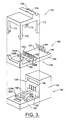
- Figure 3 is an exploded view of the socket of Figure 1 and a cap;
- Figure 4 is a cross-sectional view of the socket of Figure 1 taken along the line 4-4 of Figure 1;
- Figure 5 is a cross-sectional view of a gel-filled connector assembly including the socket of Figure 1 and the cap and taken along the same line as Figure 4;
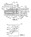
- Figure 6 is a cross-sectional view of the gel-filled connector assembly of Figure 5 and a connector and taken along the same line as Figure 4;
- Figure 7 is a front end view of a base member of the socket of Figure 1;
- Figure 8 is a fragmentary, enlarged view of a base member according to a further embodiment of the invention;
- Figure 9 is a front end view of a base member according to a further embodiment of the present invention;
- Figure 10 is a fragmentary, cross-sectional view of the base member of Figure 9 taken along the line 10-10 of Figure 9;
- Figure 11 is a fragmentary, perspective view of a base member according to a further embodiment; and
- Figure 12 is a cross-sectional view of the base member of Figure 11 taken along the line 12-12 of Figure 11.
- The present invention now will be described more fully hereinafter with reference to the accompanying drawings, in which preferred embodiments of the invention are shown. This invention may, however, be embodied in many different forms and should not be construed as limited to the embodiments set forth herein; rather, these embodiments are provided so that this disclosure will be thorough and complete, and will fully convey the scope of the invention to those skilled in the art. Like numbers refer to like elements throughout.
- With reference to Figures 5 and 6, a gel-filled connector assembly according to the present invention is shown therein and generally designated 100. The gel-filled
connector assembly 100 includes asocket 102. Asealant 110 is disposed within thesocket 102 to protect electrically conductive components thereof from dust and moisture and other corrosives. Thesealant 110 is preferably, and will hereinafter be referred to as, a gel. However, other types of sealants may be used as discussed below. - In Figure 5, the gel-filled
connector assembly 100 is shown with an associatedcap 170 mounted thereon. In Figure 6, the gel-filledconnector assembly 100 is shown with an associateddevice connector 180 connected thereto. Theconnector 180 includes a load bar orwire terminating cap 181 through which fourwires 182 are inserted. Theload bar 181 includespartition walls 188 between therespective wires 182 adjacent theends 182A of thewires 182. Thepartition walls 188 defineslots 188A within which the end portions of the wires are received as shown. Theload bar 181, and thereby thewires 182, are secured to the gel-filledconnector assembly 100 by a connectingleg 186. It will be appreciated that more than four wires and connectors other than theconnector 180 as shown and described herein may be used. - Figures 1-4 show the
socket 102 without thegel 110 for clarity. Similarly, Figure 7 shows abase member 120 forming a part of thesocket 102, also shown without thegel 110. The gel-filledconnector assembly 100 is adapted to receive and electrically connect with a suitable male plug (not shown), for example, an RJ-type plug. RJ-type plugs are well known to those of ordinary skill in the art. - Referring now to Figure 4, the
socket 102 includes thebase member 120 and aninsert member 150. Thebase member 120 has arear portion 122 andfront portion 124. Theinsert member 150 has arear portion 152 and afront portion 154. Thebase member 120 and theinsert member 150 are securely fitted together as will be better appreciated from the description that follows. It will be appreciated, however, that the inventive aspects of the present invention may be employed in sockets configured differently than described herein. - As shown, for example, in Figures 4 and 7, the
base member 120 is preferably integrally molded from a suitable plastic such as a polycarbonate, polyphenylene oxide, or polycarbonate ABS alloy. Thebase member 120 includes aplug cavity 126 adapted to receive the RJ or other type plug (not shown). A rear partition wall or tine block 125 forms the back wall of thecavity 126. A series ofguide walls 128 forming a part of thewall 125 form a "comb" defining a series oftine slots 128A. As described below, thelower edge 125A of therear wall 125 is positioned to provide apassageway 130 in thebase member 120. When theinsert member 150 is installed in part in thebase member 120, thepassageway 130 defines apassageway 130A in thesocket 102. - The
cavity 126 has interior side wall surfaces 140. Preferably, theinterior surfaces 140 are textured to increase their overall surface areas. The forwardly facingsurface 125B of therear wall 125 and/or theupper surface 157 of theinsert member 150 in thecavity 126 may also be textured. The texturing may be formed by abrading thewalls 140 and other surfaces or molding thewalls 140 and other surfaces to make the surfaces rough. Preferably, the texturing increases the surface areas of the surfaces (as compared to smooth surfaces) by at least 10% and, more preferably, by between about 20% and 66%. The textured surfaces may be roughened by sandblasting the mold from which they are formed to provide a particulate lay to the surfaces. Preferably, therough surfaces textured surfaces - The increased surface area of the textured surface is intended to provide greater contact area between the
interior surfaces 140 and thegel 110 which enhances the adhesion of thegel 110 to thesocket 102. This enhanced adhesion reduces the tendency of thegel 110 to be removed from thesocket 102 with a plug when the plug is inserted and removed. The enhanced adhesion also helps to reduce inward displacement of the gel when the plug is inserted, thereby helping to ensure that the tines remain fully covered when the plug is inserted. Additionally, the textured surface preferably engages thegel 110 to provide mechanical resistance to removal of thegel 110 from thesocket 102. - The
base member 120 further includes a cavity orreservoir 136 formed therein. Thereservoir 136 extends through portions of therear portion 122 and thefront portion 124 including extending beneath therear wall 125. -
Apertures base member 120. Also, arecess 122C is positioned in thebase member 120. Preferably, theapertures - The
insert member 150 is preferably integrally molded of a suitable plastic such as a polycarbonate, polyphenylene oxide, or polycarbonate ABS alloy.Apertures projection 152C extends from the lower surface of theinsert member 150. Also, as discussed below in more detail, a cavity ortrough 132 is positioned in the upper surface of theinsert member 150. A series of spaced apart guide walls 156 (Figure 1) define a series oftine slots 134 therebetween. - A plurality of side by side
electrical leads 160 extend lengthwise along theinsert member 150. Each lead 160 preferably includes an insulation displacement connector (hereinafter, "IDC") 162, atine 164 and a connectingportion 166. Preferably, each lead 160 is formed of a continuous and integral strip of electrically conductive metal. As best seen in Figure 4, for each lead 160, theIDC 162 projects above the upper surface of and extends through the thickness of theinsert member 150, the connectingportion 166 extends along the bottom surface of theinsert member 150, and thetine 164 is positioned in a respective one of theslots 128 and a respective one of theslots 134. Preferably, the tines are spring loaded, i.e., biased upwardly against therear wall 125. It will be appreciated that more leads 160 may be provided. In particular, there may be provided a second row ofIDCs 162 staggered with the first row ofIDCs 162 and allowing for an increased number of tines 164 (e.g., eight tines, as may be required in a data or telephone jack). For clarity, only a single row ofIDCs 162 is shown and described. - The
insert member 150 is mounted in thebase member 120 by sliding thefront end 154 through thepassageway 130. As theinsert member 150 is inserted, thetines 164 are received in, guided by and retained in spaced apart relation by thewalls 128. When theinsert member 150 is fully inserted, theprojection 152C interlocks with therecess 122C. Optionally, themembers insert member 150 and the lower edge of therear wall 125 define apassageway 130A in thepassageway 130. - Once the
socket 102 has been assembled as described above, thegel material 110 may be installed. It will be appreciated that methods of installing the gel other than as described hereinbelow may be employed. - With reference to Figures 3 and 5, prior to gel installation, the
cap 170 is mounted on thesocket 102 such that thelegs 172 snap fit over thesocket 102 and aprescribed portion 174 of the cap receives the row ofIDCs 162. Thesocket 102 is placed such that thefront portion 124 is oriented vertically over therear portion 122. An uncured gel material is then poured into thesocket 102 through thecavity 126. Thesocket 102 is configured such that each of thevarious cavities base member 120 and theinsert member 150 are filled and the exposed portions of theleads 160 are covered. The uncured gel material flows through and into theslots 128A and thepassageway 130A to fill thetrough 132 and to cover theIDCs 162 as shown. Notably, thepassageway 130A provides a substantial passageway for flow of the gel material allowing for fast and consistent flow of the uncured gel material from thecavity 126 to the rear portion of thesocket 102. Flow of the gel material into these areas is facilitated by anair vent 176 formed in thecap 170. Additionally, gel material flows through theslots 134 to fill thereservoir 136. Once thecavities passageway 130A have been filled, thesocket 102 is preferably tilted such that thetines 164 are oriented substantially parallel with the horizontal plane. The gel material is then cured by suitable means to form thegel 110. In the preferred embodiment, as shown, the gel covers thetines 164 while leaving an unfilled portion of thecavity 126 to accept a plug. - The
environmental sealant 110 is preferably a hydrophobic dielectric designed to exclude moisture and insulate the wires and contacts. Gels are preferred, with the most preferred being silicone gels. The preferred gels have a cohesiveness greater than their tack (adhesion to other surfaces), so that when the plug is removed from thesocket 126, thegel 110 will release the plug rather than separating from the main body of gel within the socket. The gel requires a sufficient adhesion, however, so that it will form an acceptable seal around the contacts, wires, and other portions of the apparatus in need of environmental protection. - The sealant should have a hardness sufficient to provide lasting protection against environmental contaminants. On the other hand, the sealant should be soft enough to be displaced by the plug and conform to the shape of the socket assembly and adequately seal it while allowing an acceptable electrical connection between the socket and the plug. The gel's hardness may also impact a customer preference: an audible "click" when the RJ-type plug is fully inserted and latches into the RJ-type socket. If the sealant is too stiff, this click may be muted.
- A wide variety of sealants are available for this use, including, for example, elastic hot melt materials, greases, and flexible epoxies. Preferably, the sealant is a dielectric gel such as an oil or plasticizer extended aliphatic urethane gels, urea gels, silicone gels, and thermoplastic gels like styrene-ethylene-butylene-styrene or styrene-ethylene-propylene-styrene, or other soft gels having the required properties below whether or not oil or plasticizer extended, including those disclosed in
U.S. Pat. Nos. 4,634,207 ;4,600,261 ;4,643,924 ;4,865,905 ;4,662,692 ;4,595,635 ;4,680,233 ;4,716,183 ;4,718,678 ;4,777,063 ; and4,942,270 , which are completely incorporated herein by reference for all purposes. - Preferred gels used in conjunction with the present invention include those having a cone penetration value from about 50 to about 350× 10-1 mm, more preferably about 100 to about 300×10-1 mm, and most preferably about 100 to about 250×10-1 mm. Preferred gels also have an ultimate elongation of at least about 100%, more preferably at least about 500% to 1000%, and most preferably greater than 1400%. Alternatively from cone penetration, another measurement for hardness is Voland hardness. The Voland hardness is generally measured on a Voland texture analyzer apparatus. Voland hardnesses from about 10 grams to at least about 50 grams are acceptable for the gel, with preferred gels having Voland hardnesses from about 20 to about 40 grams. The preferred environmental sealant is a silicone gel having a Voland hardness of about 29±6 grams, a stress relaxation of about 28±10%, and a tack of about 17±5 grams.
- The cavities of the RJ-type plug (not shown) are also preferably substantially completely filled with the
gel 110. - Following the curing step, the
gel 110 is distributed through thesocket 102 as shown in Figure 5, and with reference to Figure 4. Aportion 110A of the gel fills a substantial portion of thecavity 126 and covers thetines 164. Aportion 110B of the gel fills theslots 128A and aportion 110C of the gel fills thepassageway 130A. Aportion 110D of the gel fills the space between therear wall 125 and theIDCs 162. Aportion 110E of the gel surrounds and extends between theIDCs 162. Aportion 110F of the gel fills thetrough 132. A portion 110G of the gel fills theslots 134. Aportion 110H of the gel fills thereservoir 136. - When the
connector 180 is mounted on the gel-filledconnector assembly 100 as shown in Figure 6, eachIDC 162 displaces the insulation of a respective one of thewires 182 and makes electrical contact with the wire conductor. It will be appreciated that when theconnector 180 is engaged with the gel-filled connector assembly 100 (and also when the RJ plug is inserted (not shown)), theIDCs 162, thetines 164, and the connectingportions 166 are fully encapsulated or "sealed" in thesocket 102 and thegel 110 such that they are protected from moisture or contaminates from the environment. Notably, thegel portion 110H in thereservoir 136 covers the connectingportions 166. In this way, thegel portion 110H also serves to electrically isolate the respective connectingportions 166 from one another. Such electrical isolation is of particular benefit when thedevices 100 are used in humid environments which might otherwise cause short circuiting between adjacent ones of the connectingportions 166. Thegel portion 110H also serves to protect the connectingportions 166 from corrosion and the like. The wire ends 182A are received in thegel portion 110F in thetrough 132. Similarly, thegel portion 110F serves to electrically isolate the wire ends 182A from one another and to protect the wire ends from contamination. Also, part of thegel portion 110D fills some or all of theslots 188A of theload bar 181. - As shown in Figure 6, the
apertures leg 186 of theconnector 180. Theapertures connector 180. It will be appreciated that other means for attaching theconnector 180 to thesocket 102 may be provided. - As discussed above, it is particularly contemplated that the textured surfaces of the plug cavity may have a raised pattern. A preferred raised pattern is illustrated in Figure 8 which shows an enlarged, fragmentary view of a
side wall 240 of analternative base member 220 otherwise corresponding to thebase member 120 and which may be used in place thereof. Theside wall 240 corresponds to theside wall 140 except that theside wall 240 includes a plurality of raised protrusions orbumps 242 extending into theplug cavity 226. Thebumps 242 may be arranged in a random, regular or semi-regular pattern. Thebumps 242 are preferably molded into thebase member 220, and a reverse pattern may be machined or electric discharge machined into the mold. Bumps may also be formed on the forwardly facing surface of the rear wall (not shown) and/or the upper surface of the portion of the insert member (not shown) in thecavity 226. Thebumps 242 serve to increase the surface area for engagement with the gel (not shown) as well as to mechanically retain the gel. Preferably, the bumps are substantially half-spheres having a radius of between about 0.005 inch and 0.030 inch. - In the embodiment of Figure 8, the
bumps 242 are spaced apart. According to a further embodiment (not shown), the bumps are intertangential such that the bumps are arranged as densely as feasible. The bumps are otherwise formed as described with regard to thebase member 220. - With reference to Figures 9 and 10, a
base member 320 according to a further embodiment is shown therein. Thebase member 320 may be used in place of thebase member 120 as described above. Except as discussed below, thebase member 320 is preferably formed in the same configuration, in the same manner, and from the same materials as thebase member 120. Aplug cavity 326 is formed in thefront portion 324 of thebase member 320. The interior surfaces 340 of theplug cavity 326 of thebase member 320 include a plurality of integrally moldedribs 342 extending inwardly therefrom. Theribs 342 serve to increase the surface area for engagement with the gel (not shown) in similar manner to the raised pattern described above with regard to thebase member 220. Ribs (not shown) may also be formed on the forwardly facingsurface 325A of therear wall 325 and/or the exposed surface of the insert member (not shown) in thecavity 326. The ribs may be disposed at angles other than as shown in the illustrated embodiment. - Raised patterns of configurations other than those described above may be employed. For example, the raised patterns may be pyramids.
- With reference to Figures 11 and 12, a
base member 420 according to a further embodiment of the present invention is shown therein. Thebase member 420 may be used in place of thebase member 120 as described above. Aplug cavity 426 is formed in thefront portion 424 of thebase member 420. The interior surfaces 440 of thecavity 426 are covered by moldedinserts 442. The molded inserts 442 are formed of a material exhibiting greater adhesion with the gel (not shown) than the material from which thebase member 420 is formed. Preferably, the mold inserts 442 are formed from elastomeric material. More preferably, the mold inserts 442 are formed from silicone rubber, and, more preferably, from addition-cured silicone rubber. The mold inserts 442 are secured to the walls of thebase member 420 in the illustrated embodiment by respective T-shapedprojections 442A andnibs 442B which are received in complementary shapedslots inserts 442 may be used as an alternative to or in addition to theelements inserts 442 may be bonded or adhered to the interior surfaces 440. Preferably, theslots base portion 420 and the moldedinserts 442 are formed and mounted in thecavity 426 by injection molding. Theinserts 442 enhance the mechanical adhesion between the gel and the base member and may also form a chemical bond with the gel. Theinserts 442 may also include integrally molded bumps, ribs or other raised patterns or other texturing as described above to engage the gel in thecavity 426. - The foregoing is illustrative of the present invention and is not to be construed as limiting thereof. Although a few exemplary embodiments of this invention have been described, those skilled in the art will readily appreciate that many modifications are possible in the exemplary embodiments without materially departing from the novel teachings and advantages of this invention. Accordingly, all such modifications are intended to be included within the scope of this invention as defined in the claims. In the claims, means-plus-function clauses are intended to cover the structures described herein as performing the recited function and not only structural equivalents but also equivalent structures. Therefore, it is to be understood that the foregoing is illustrative of the present invention and is not to be construed as limited to the specific embodiments disclosed, and that modifications to the disclosed embodiments, as well as other embodiments, are intended to be included within the scope of the appended claims. The invention is defined by the following claims, with equivalents of the claims to be included therein.
Claims (23)
- A sealant-filled connector assembly (100) for use with a connector plug, said connector assembly comprising:a socket (102) including:a plug cavity (126) formed therein adapted to receive a connector plug; andan electrically conductive lead (160) having a first contact (164) disposed in said plug cavity, a second contact (162) positioned at an opposing end of said lead, and a connecting portion (166) extending between and joiningsaid first and second contacts, said connector assembly further comprising:a reservoir (136) and an insert member (150) located in said socket adjacent said connecting portion of said lead; andan environmental sealant (110) disposed in said reservoir and engaging at least a portion of said connecting portion, characterised in that said connecting portion extends along a bottom surface of said insert member.
- A connector assembly as claimed in Claim 1 wherein said sealant is further disposed in said plug cavity.
- A connector assembly as claimed in Claim 1 or Claim 2 wherein said connecting portion is entirely surrounded by said sealant and said socket.
- A connector assembly as claimed in any preceding Claim wherein said socket includes a base member (120), and said first and second contacts are mounted on said insert member and said reservoir is formed in said base member.
- A scalant-filled connector assembly as claimed in any preceding claim for use with a device connector (180), said socket being adapted to receive a device connector, having exposed wire ends, and said socket including a trough (132) located in said socket, said trough positioned and configured such that, when the device connector is mounted on said socket, the wire ends (182A) of the device connector are received in said trough; and said environmental sealant (110) being disposed further in said trough whereby, when the device connector is mounted on said socket, said sealant surrounds the wire ends.
- A connector assembly as claimed in Claim 5 when dependent on Claim 4 wherein said trough is formed in said insert member.
- A connector assembly as claimed in any preceding claim wherein said plug cavity comprises an interior wall 140, said interior wall being textured to enhance adhesion between the sealant and said socket.
- A connector assembly as claimed in Claim 7 wherein said environmental sealant disposed in said plug cavity engages said interior wall.
- A connector assembly as claimed in any preceding claim wherein said sealant is a gel.
- A connector assembly as claimed in Claim 8 wherein said interior wall has a rough surface having rating of at least N12 per ISO 1320:1992.
- A connector assembly as claimed in Claim 10 including a raised, inwardly projecting pattern on said interior wall.
- A connector assembly as claimed in Claim 11 wherein said raised pattern is integrally molded with said interior wall.
- A connector assembly as claimed in Claim 11 or Claim 12 wherein said raised pattern includes a plurality of raised bumps (242).
- A connector assembly as claimed in any of Claims 11 to 13 wherein said raised pattern includes a plurality of ribs (342).
- A connector assembly as claimed in Claim 7 wherein said plug cavity has an interior wall (140) and includes an engagement member (442) mounted on said interior wall, said engagement member formed of a material providing enhanced adhesion with said gel as compared to the material of said interior wall.
- A connector assembly as claimed in Claim 15 wherein said engagement member is formed of an elastomeric material.
- A connector assembly as claimed in Claim 15 or Claim 16 wherein said engagement member is bonded to said interior wall.
- A connector assembly as claimed in any of Claims 15 to 17 wherein said engagement member is mechanically attached to said interior wall.
- A sealant-filled connector assembly as claimed in any preceding claim wherein said socket comprises:a first portion (152);a second portion (154) adjacent said first portion and adapted to receive a device connector;said plug cavity (126) being formed in said first portion,said electrically conductive lead (160) extending along said first and second portions, said second contact (162) being positioned on said: second portion, and said connecting portion (166) extending between and joining said first and second contacts;a partition wall (125) positioned between said plug cavity and said second portion and between said first and second contacts;a connecting passageway (130/130A) formed in said partition wall, said passageway providing fluid communication between said plug cavity and said second portion;wherein said sealant is further disposed in and extending continuously through said plug cavity and said passageway and into said second portion.
- A connector assembly as claimed in Claim 19 wherein said sealant extends continuously from said passageway to said second contact and surrounds at least a portion of each of said first and second contacts.
- A connector assembly as claimed in any preceding claim wherein said first contact is spring biased within said plug cavity and said second contact is an insulation displacement connector.
- A connector assembly as claimed in Claim 19 including a slot (128A) located in said partition wall and wherein said first contact is received in said slot.
- A method of forming a sealant-filled connector assembly for use with a connector plug, said method comprising the steps of:(a) providing said connector assembly comprising:a socket (102) including:a plug cavity (126) formed therein adapted to receive a connector plug; andan electrically conductive lead (160) having a first contact (164) disposed in said plug cavity, a second contact (162) positioned at an opposing end of said lead, and a connecting portion (166) extending between and joining said first and second contacts, said connector assembly further comprising:a reservoir (136) and an insert member (150) located in said socketadjacent said connecting portion of said lead, said connecting portion extending along a bottom surface of said insert member; and(b) placing an uncured sealant material (110) in the said plug cavity such that the sealant material extends from the plug cavity and into the said reservoir to engage at least a portion of said connecting portion(c) curing the sealant material to form an environmental seal in the socket.
Applications Claiming Priority (3)
| Application Number | Priority Date | Filing Date | Title |
|---|---|---|---|
| US09/343,319 US6224419B1 (en) | 1999-06-30 | 1999-06-30 | Sealant-filled electrical connector and method for forming the same |
| US343319 | 1999-06-30 | ||
| PCT/US2000/018203 WO2001001522A2 (en) | 1999-06-30 | 2000-06-29 | Sealant-filled electrical connector and method for forming the same |
Publications (2)
| Publication Number | Publication Date |
|---|---|
| EP1218971A2 EP1218971A2 (en) | 2002-07-03 |
| EP1218971B1 true EP1218971B1 (en) | 2007-12-05 |
Family
ID=23345608
Family Applications (1)
| Application Number | Title | Priority Date | Filing Date |
|---|---|---|---|
| EP00950280A Expired - Lifetime EP1218971B1 (en) | 1999-06-30 | 2000-06-29 | Sealant-filled electrical connector and method for forming the same |
Country Status (10)
| Country | Link |
|---|---|
| US (2) | US6224419B1 (en) |
| EP (1) | EP1218971B1 (en) |
| AT (1) | ATE380407T1 (en) |
| AU (1) | AU772537B2 (en) |
| BR (1) | BR0009429A (en) |
| CA (1) | CA2368070A1 (en) |
| DE (1) | DE60037326D1 (en) |
| ES (1) | ES2296630T3 (en) |
| MX (1) | MXPA01009841A (en) |
| WO (1) | WO2001001522A2 (en) |
Families Citing this family (24)
| Publication number | Priority date | Publication date | Assignee | Title |
|---|---|---|---|---|
| GB0031551D0 (en) * | 2000-12-22 | 2001-02-07 | 3D Instr Ltd | Switched mode circuit topologies |
| JP2002367716A (en) * | 2001-06-04 | 2002-12-20 | Sumitomo Wiring Syst Ltd | Waterproof connector |
| US6848949B2 (en) * | 2002-04-22 | 2005-02-01 | Tyco Electronics Corporation | Sealant-filled connector assemblies for use with connector plugs and methods for forming the same |
| US6666714B1 (en) * | 2002-11-06 | 2003-12-23 | Hon Hai Precision Ind. Co., Ltd. | Electrical connector with terminal protector |
| US6971897B1 (en) | 2003-10-29 | 2005-12-06 | Tyco Electronics Corporation | Gel-filled telephone jack |
| US7044776B2 (en) * | 2003-12-02 | 2006-05-16 | King Jr Lloyd Herbert | Wire connector |
| JP2005322749A (en) * | 2004-05-07 | 2005-11-17 | Denso Corp | Structure for sealing connection terminal |
| US7540759B2 (en) * | 2004-09-23 | 2009-06-02 | Corning Cable Systems Llc | Environmentally sealed terminating device and sealing gel |
| US6984154B1 (en) * | 2005-01-25 | 2006-01-10 | Beam-Chi Jee | Crimping mechanism of a telephone connector crimper |
| US7101226B1 (en) * | 2005-06-08 | 2006-09-05 | Wave Intellectual Property, Inc. | Compact contour electrical converter package |
| EP1938428B1 (en) * | 2005-09-19 | 2011-03-30 | Molex Incorporated | Connection system and squib connector therefore |
| US20070141894A1 (en) * | 2005-12-15 | 2007-06-21 | Horizon Technologies, Inc. | Plug with supplemental memory |
| US20070145945A1 (en) * | 2005-12-28 | 2007-06-28 | Mcginley James W | Method and apparatus to authenticate battery charging device |
| US20070164704A1 (en) * | 2006-01-13 | 2007-07-19 | Horizon Technologies, Inc. | Plug with supplemental memory |
| US20080076300A1 (en) * | 2006-09-26 | 2008-03-27 | A-Sheng Yang | Car inside lamp adaptor device |
| US7384297B2 (en) * | 2006-11-07 | 2008-06-10 | King Jr Lloyd Herbert | Wire connector |
| US7431611B2 (en) * | 2006-11-07 | 2008-10-07 | The Patent Store, Llc | Wire connector |
| US7549898B2 (en) * | 2007-09-26 | 2009-06-23 | Fci Americas Technology, Inc. | Waterproof electrical connector |
| DE102008013317B4 (en) * | 2008-03-10 | 2010-10-14 | Adc Gmbh | Method for producing a wire connection strip with gel filling |
| US7985094B2 (en) * | 2008-09-15 | 2011-07-26 | Adc Gmbh | Connector block |
| US8845361B2 (en) | 2011-11-08 | 2014-09-30 | Thomas & Betts International Llc | Explosion-proof electrical fitting |
| EP2970597A4 (en) | 2013-03-12 | 2016-10-12 | Tyco Electronics Corp | Hybrid thermoplastic gels and their methods of making |
| EP3464413B1 (en) | 2016-05-26 | 2021-12-01 | Corning Optical Communications LLC | Material formulation for over mold cover fiber optic cable |
| CN113517599B (en) * | 2021-04-29 | 2022-02-18 | 如皋市卓凡电子元件有限公司 | Self-sealing type automobile connector and using method thereof |
Family Cites Families (16)
| Publication number | Priority date | Publication date | Assignee | Title |
|---|---|---|---|---|
| US4634207A (en) * | 1982-10-12 | 1987-01-06 | Raychem Corporation | Apparatus and method for protection of a substrate |
| US5111497A (en) | 1990-09-17 | 1992-05-05 | Raychem Corporation | Alarm and test system for a digital added main line |
| US5195125A (en) | 1990-09-17 | 1993-03-16 | Raychem Corporation | Gel filled RJ11 connector |
| US5246383A (en) | 1990-09-17 | 1993-09-21 | Raychem Corporation | Gel filled electrical connector |
| US5376019A (en) | 1990-09-17 | 1994-12-27 | Raychem Corporation | Gel filled modular electrical connecting block |
| US5360945A (en) * | 1991-05-01 | 1994-11-01 | Raychem Corporation | Cable seal |
| US5359654A (en) | 1992-05-12 | 1994-10-25 | Raychem Corporation | Telecommunications network interface assembly |
| FR2694456B1 (en) | 1992-07-31 | 1994-09-09 | Pouyet Int | "Modular jack" type female socket with integrated connectors. |
| GB9316371D0 (en) * | 1993-08-06 | 1993-09-22 | Amp Gmbh | Gel sealed connector |
| JPH07135044A (en) * | 1993-11-11 | 1995-05-23 | Yazaki Corp | Connector |
| US5595504A (en) * | 1994-09-26 | 1997-01-21 | Siecor Corporation | Sealed connector |
| EP0805519B1 (en) | 1996-05-02 | 2002-06-26 | Pouyet S.A. | Socket with integrated terminals and backplane connection with insulation displacing contacts |
| EP0805518B1 (en) | 1996-05-02 | 2002-05-08 | Pouyet S.A. | Connecting device with insulation displacing contacts |
| DE69621909T2 (en) | 1996-05-02 | 2002-10-31 | Pouyet Sa | Method and connection arrangement by insulation cutting contact |
| US5934934A (en) * | 1997-04-22 | 1999-08-10 | Communication Systems, Inc. | Shielded couplers |
| JP3285004B2 (en) * | 1999-03-18 | 2002-05-27 | 住友電装株式会社 | connector |
-
1999
- 1999-06-30 US US09/343,319 patent/US6224419B1/en not_active Expired - Lifetime
-
2000
- 2000-06-29 ES ES00950280T patent/ES2296630T3/en not_active Expired - Lifetime
- 2000-06-29 CA CA002368070A patent/CA2368070A1/en not_active Abandoned
- 2000-06-29 AT AT00950280T patent/ATE380407T1/en not_active IP Right Cessation
- 2000-06-29 BR BR0009429-3A patent/BR0009429A/en not_active IP Right Cessation
- 2000-06-29 WO PCT/US2000/018203 patent/WO2001001522A2/en active IP Right Grant
- 2000-06-29 EP EP00950280A patent/EP1218971B1/en not_active Expired - Lifetime
- 2000-06-29 AU AU63404/00A patent/AU772537B2/en not_active Ceased
- 2000-06-29 MX MXPA01009841A patent/MXPA01009841A/en active IP Right Grant
- 2000-06-29 DE DE60037326T patent/DE60037326D1/en not_active Expired - Lifetime
-
2001
- 2001-04-25 US US09/840,744 patent/US6475029B2/en not_active Expired - Lifetime
Also Published As
| Publication number | Publication date |
|---|---|
| ES2296630T3 (en) | 2008-05-01 |
| AU772537B2 (en) | 2004-04-29 |
| DE60037326D1 (en) | 2008-01-17 |
| US6475029B2 (en) | 2002-11-05 |
| WO2001001522A3 (en) | 2002-04-25 |
| BR0009429A (en) | 2002-02-13 |
| ATE380407T1 (en) | 2007-12-15 |
| EP1218971A2 (en) | 2002-07-03 |
| US20010014558A1 (en) | 2001-08-16 |
| AU6340400A (en) | 2001-01-31 |
| MXPA01009841A (en) | 2002-06-21 |
| CA2368070A1 (en) | 2001-01-04 |
| WO2001001522A2 (en) | 2001-01-04 |
| US6224419B1 (en) | 2001-05-01 |
Similar Documents
| Publication | Publication Date | Title |
|---|---|---|
| EP1218971B1 (en) | Sealant-filled electrical connector and method for forming the same | |
| US5376019A (en) | Gel filled modular electrical connecting block | |
| KR101030172B1 (en) | Connector assembly for use with connector plug | |
| US4978317A (en) | Connector with visual indicator | |
| US3471822A (en) | Terminal junction system for electrical conductors | |
| CA1290040C (en) | Connector bank for telecommunication devices | |
| JPH07508124A (en) | Line connection equipment for telecommunications networks | |
| RU95122694A (en) | ENVIRONMENTALLY SEALED ELECTRICAL CONNECTOR, METHOD FOR MANUFACTURING THE SPRING UNIT OF THE TELEPHONE CONNECTOR, THE SPRING UNIT OF THE TELEPHONE CONNECTOR, THE FIELD CONNECTOR IS HERMET | |
| US20030157824A1 (en) | Power cord connecting set | |
| US6913481B2 (en) | Modular jack with visual indicator | |
| US5595504A (en) | Sealed connector | |
| US5846099A (en) | Connector device with overvoltage protection | |
| EP0623976A2 (en) | Module for telephone line conductor pair having single protector unit | |
| US5470250A (en) | Bridging terminal block | |
| US5476388A (en) | Connector block | |
| US6077112A (en) | Connector with improved dielectric strength | |
| CA1246703A (en) | Electrical connector receptacle adapted to be mounted on printed wiring card | |
| KR830002463Y1 (en) | Outlet Adapter for Modular Telephone Cord |
Legal Events
| Date | Code | Title | Description |
|---|---|---|---|
| PUAI | Public reference made under article 153(3) epc to a published international application that has entered the european phase |
Free format text: ORIGINAL CODE: 0009012 |
|
| 17P | Request for examination filed |
Effective date: 20010921 |
|
| AK | Designated contracting states |
Kind code of ref document: A2 Designated state(s): AT BE CH CY DE DK ES FI FR GB GR IE IT LI LU MC NL PT SE |
|
| 17Q | First examination report despatched |
Effective date: 20060925 |
|
| 17Q | First examination report despatched |
Effective date: 20060925 |
|
| GRAP | Despatch of communication of intention to grant a patent |
Free format text: ORIGINAL CODE: EPIDOSNIGR1 |
|
| GRAS | Grant fee paid |
Free format text: ORIGINAL CODE: EPIDOSNIGR3 |
|
| GRAA | (expected) grant |
Free format text: ORIGINAL CODE: 0009210 |
|
| AK | Designated contracting states |
Kind code of ref document: B1 Designated state(s): AT BE CH CY DE DK ES FI FR GB GR IE IT LI LU MC NL PT SE |
|
| REG | Reference to a national code |
Ref country code: GB Ref legal event code: FG4D |
|
| REG | Reference to a national code |
Ref country code: IE Ref legal event code: FG4D |
|
| REG | Reference to a national code |
Ref country code: CH Ref legal event code: EP |
|
| REF | Corresponds to: |
Ref document number: 60037326 Country of ref document: DE Date of ref document: 20080117 Kind code of ref document: P |
|
| PG25 | Lapsed in a contracting state [announced via postgrant information from national office to epo] |
Ref country code: CH Free format text: LAPSE BECAUSE OF FAILURE TO SUBMIT A TRANSLATION OF THE DESCRIPTION OR TO PAY THE FEE WITHIN THE PRESCRIBED TIME-LIMIT Effective date: 20071205 Ref country code: SE Free format text: LAPSE BECAUSE OF FAILURE TO SUBMIT A TRANSLATION OF THE DESCRIPTION OR TO PAY THE FEE WITHIN THE PRESCRIBED TIME-LIMIT Effective date: 20080305 Ref country code: LI Free format text: LAPSE BECAUSE OF FAILURE TO SUBMIT A TRANSLATION OF THE DESCRIPTION OR TO PAY THE FEE WITHIN THE PRESCRIBED TIME-LIMIT Effective date: 20071205 Ref country code: NL Free format text: LAPSE BECAUSE OF FAILURE TO SUBMIT A TRANSLATION OF THE DESCRIPTION OR TO PAY THE FEE WITHIN THE PRESCRIBED TIME-LIMIT Effective date: 20071205 |
|
| REG | Reference to a national code |
Ref country code: ES Ref legal event code: FG2A Ref document number: 2296630 Country of ref document: ES Kind code of ref document: T3 |
|
| PG25 | Lapsed in a contracting state [announced via postgrant information from national office to epo] |
Ref country code: FI Free format text: LAPSE BECAUSE OF FAILURE TO SUBMIT A TRANSLATION OF THE DESCRIPTION OR TO PAY THE FEE WITHIN THE PRESCRIBED TIME-LIMIT Effective date: 20071205 |
|
| NLV1 | Nl: lapsed or annulled due to failure to fulfill the requirements of art. 29p and 29m of the patents act | ||
| REG | Reference to a national code |
Ref country code: CH Ref legal event code: PL |
|
| PG25 | Lapsed in a contracting state [announced via postgrant information from national office to epo] |
Ref country code: AT Free format text: LAPSE BECAUSE OF FAILURE TO SUBMIT A TRANSLATION OF THE DESCRIPTION OR TO PAY THE FEE WITHIN THE PRESCRIBED TIME-LIMIT Effective date: 20071205 |
|
| PG25 | Lapsed in a contracting state [announced via postgrant information from national office to epo] |
Ref country code: BE Free format text: LAPSE BECAUSE OF FAILURE TO SUBMIT A TRANSLATION OF THE DESCRIPTION OR TO PAY THE FEE WITHIN THE PRESCRIBED TIME-LIMIT Effective date: 20071205 |
|
| PG25 | Lapsed in a contracting state [announced via postgrant information from national office to epo] |
Ref country code: PT Free format text: LAPSE BECAUSE OF FAILURE TO SUBMIT A TRANSLATION OF THE DESCRIPTION OR TO PAY THE FEE WITHIN THE PRESCRIBED TIME-LIMIT Effective date: 20080505 |
|
| EN | Fr: translation not filed | ||
| PLBE | No opposition filed within time limit |
Free format text: ORIGINAL CODE: 0009261 |
|
| STAA | Information on the status of an ep patent application or granted ep patent |
Free format text: STATUS: NO OPPOSITION FILED WITHIN TIME LIMIT |
|
| PG25 | Lapsed in a contracting state [announced via postgrant information from national office to epo] |
Ref country code: DK Free format text: LAPSE BECAUSE OF FAILURE TO SUBMIT A TRANSLATION OF THE DESCRIPTION OR TO PAY THE FEE WITHIN THE PRESCRIBED TIME-LIMIT Effective date: 20071205 Ref country code: DE Free format text: LAPSE BECAUSE OF FAILURE TO SUBMIT A TRANSLATION OF THE DESCRIPTION OR TO PAY THE FEE WITHIN THE PRESCRIBED TIME-LIMIT Effective date: 20080306 |
|
| 26N | No opposition filed |
Effective date: 20080908 |
|
| PG25 | Lapsed in a contracting state [announced via postgrant information from national office to epo] |
Ref country code: MC Free format text: LAPSE BECAUSE OF NON-PAYMENT OF DUE FEES Effective date: 20080630 Ref country code: GR Free format text: LAPSE BECAUSE OF FAILURE TO SUBMIT A TRANSLATION OF THE DESCRIPTION OR TO PAY THE FEE WITHIN THE PRESCRIBED TIME-LIMIT Effective date: 20080306 |
|
| GBPC | Gb: european patent ceased through non-payment of renewal fee |
Effective date: 20080629 |
|
| PG25 | Lapsed in a contracting state [announced via postgrant information from national office to epo] |
Ref country code: IE Free format text: LAPSE BECAUSE OF NON-PAYMENT OF DUE FEES Effective date: 20080630 Ref country code: FR Free format text: LAPSE BECAUSE OF FAILURE TO SUBMIT A TRANSLATION OF THE DESCRIPTION OR TO PAY THE FEE WITHIN THE PRESCRIBED TIME-LIMIT Effective date: 20081003 |
|
| PG25 | Lapsed in a contracting state [announced via postgrant information from national office to epo] |
Ref country code: GB Free format text: LAPSE BECAUSE OF NON-PAYMENT OF DUE FEES Effective date: 20080629 |
|
| PG25 | Lapsed in a contracting state [announced via postgrant information from national office to epo] |
Ref country code: CY Free format text: LAPSE BECAUSE OF FAILURE TO SUBMIT A TRANSLATION OF THE DESCRIPTION OR TO PAY THE FEE WITHIN THE PRESCRIBED TIME-LIMIT Effective date: 20071205 |
|
| PG25 | Lapsed in a contracting state [announced via postgrant information from national office to epo] |
Ref country code: LU Free format text: LAPSE BECAUSE OF NON-PAYMENT OF DUE FEES Effective date: 20080629 |
|
| PG25 | Lapsed in a contracting state [announced via postgrant information from national office to epo] |
Ref country code: IT Free format text: LAPSE BECAUSE OF NON-PAYMENT OF DUE FEES Effective date: 20080630 |
|
| PGFP | Annual fee paid to national office [announced via postgrant information from national office to epo] |
Ref country code: ES Payment date: 20170705 Year of fee payment: 18 |
|
| REG | Reference to a national code |
Ref country code: ES Ref legal event code: FD2A Effective date: 20190916 |
|
| PG25 | Lapsed in a contracting state [announced via postgrant information from national office to epo] |
Ref country code: ES Free format text: LAPSE BECAUSE OF NON-PAYMENT OF DUE FEES Effective date: 20180630 |