EP1218965B1 - Apparatus for cooling with a phase change material and heat pipes - Google Patents
Apparatus for cooling with a phase change material and heat pipes Download PDFInfo
- Publication number
- EP1218965B1 EP1218965B1 EP00965034A EP00965034A EP1218965B1 EP 1218965 B1 EP1218965 B1 EP 1218965B1 EP 00965034 A EP00965034 A EP 00965034A EP 00965034 A EP00965034 A EP 00965034A EP 1218965 B1 EP1218965 B1 EP 1218965B1
- Authority
- EP
- European Patent Office
- Prior art keywords
- housing
- chamber
- heat
- absorbing material
- heat absorbing
- Prior art date
- Legal status (The legal status is an assumption and is not a legal conclusion. Google has not performed a legal analysis and makes no representation as to the accuracy of the status listed.)
- Expired - Lifetime
Links
Images


Classifications
-
- H—ELECTRICITY
- H05—ELECTRIC TECHNIQUES NOT OTHERWISE PROVIDED FOR
- H05K—PRINTED CIRCUITS; CASINGS OR CONSTRUCTIONAL DETAILS OF ELECTRIC APPARATUS; MANUFACTURE OF ASSEMBLAGES OF ELECTRICAL COMPONENTS
- H05K7/00—Constructional details common to different types of electric apparatus
- H05K7/20—Modifications to facilitate cooling, ventilating, or heating
- H05K7/2029—Modifications to facilitate cooling, ventilating, or heating using a liquid coolant with phase change in electronic enclosures
- H05K7/20336—Heat pipes, e.g. wicks or capillary pumps
-
- B—PERFORMING OPERATIONS; TRANSPORTING
- B64—AIRCRAFT; AVIATION; COSMONAUTICS
- B64G—COSMONAUTICS; VEHICLES OR EQUIPMENT THEREFOR
- B64G1/00—Cosmonautic vehicles
- B64G1/22—Parts of, or equipment specially adapted for fitting in or to, cosmonautic vehicles
- B64G1/46—Arrangements or adaptations of devices for control of environment or living conditions
- B64G1/50—Arrangements or adaptations of devices for control of environment or living conditions for temperature control
- B64G1/506—Heat pipes
-
- F—MECHANICAL ENGINEERING; LIGHTING; HEATING; WEAPONS; BLASTING
- F28—HEAT EXCHANGE IN GENERAL
- F28D—HEAT-EXCHANGE APPARATUS, NOT PROVIDED FOR IN ANOTHER SUBCLASS, IN WHICH THE HEAT-EXCHANGE MEDIA DO NOT COME INTO DIRECT CONTACT
- F28D15/00—Heat-exchange apparatus with the intermediate heat-transfer medium in closed tubes passing into or through the conduit walls ; Heat-exchange apparatus employing intermediate heat-transfer medium or bodies
- F28D15/02—Heat-exchange apparatus with the intermediate heat-transfer medium in closed tubes passing into or through the conduit walls ; Heat-exchange apparatus employing intermediate heat-transfer medium or bodies in which the medium condenses and evaporates, e.g. heat pipes
- F28D15/0275—Arrangements for coupling heat-pipes together or with other structures, e.g. with base blocks; Heat pipe cores
-
- F—MECHANICAL ENGINEERING; LIGHTING; HEATING; WEAPONS; BLASTING
- F28—HEAT EXCHANGE IN GENERAL
- F28D—HEAT-EXCHANGE APPARATUS, NOT PROVIDED FOR IN ANOTHER SUBCLASS, IN WHICH THE HEAT-EXCHANGE MEDIA DO NOT COME INTO DIRECT CONTACT
- F28D20/00—Heat storage plants or apparatus in general; Regenerative heat-exchange apparatus not covered by groups F28D17/00 or F28D19/00
- F28D20/02—Heat storage plants or apparatus in general; Regenerative heat-exchange apparatus not covered by groups F28D17/00 or F28D19/00 using latent heat
- F28D20/023—Heat storage plants or apparatus in general; Regenerative heat-exchange apparatus not covered by groups F28D17/00 or F28D19/00 using latent heat the latent heat storage material being enclosed in granular particles or dispersed in a porous, fibrous or cellular structure
-
- F—MECHANICAL ENGINEERING; LIGHTING; HEATING; WEAPONS; BLASTING
- F28—HEAT EXCHANGE IN GENERAL
- F28F—DETAILS OF HEAT-EXCHANGE AND HEAT-TRANSFER APPARATUS, OF GENERAL APPLICATION
- F28F13/00—Arrangements for modifying heat-transfer, e.g. increasing, decreasing
- F28F13/003—Arrangements for modifying heat-transfer, e.g. increasing, decreasing by using permeable mass, perforated or porous materials
-
- H—ELECTRICITY
- H01—ELECTRIC ELEMENTS
- H01Q—ANTENNAS, i.e. RADIO AERIALS
- H01Q1/00—Details of, or arrangements associated with, antennas
- H01Q1/02—Arrangements for de-icing; Arrangements for drying-out ; Arrangements for cooling; Arrangements for preventing corrosion
-
- F—MECHANICAL ENGINEERING; LIGHTING; HEATING; WEAPONS; BLASTING
- F25—REFRIGERATION OR COOLING; COMBINED HEATING AND REFRIGERATION SYSTEMS; HEAT PUMP SYSTEMS; MANUFACTURE OR STORAGE OF ICE; LIQUEFACTION SOLIDIFICATION OF GASES
- F25D—REFRIGERATORS; COLD ROOMS; ICE-BOXES; COOLING OR FREEZING APPARATUS NOT OTHERWISE PROVIDED FOR
- F25D3/00—Devices using other cold materials; Devices using cold-storage bodies
-
- F—MECHANICAL ENGINEERING; LIGHTING; HEATING; WEAPONS; BLASTING
- F28—HEAT EXCHANGE IN GENERAL
- F28F—DETAILS OF HEAT-EXCHANGE AND HEAT-TRANSFER APPARATUS, OF GENERAL APPLICATION
- F28F2265/00—Safety or protection arrangements; Arrangements for preventing malfunction
- F28F2265/12—Safety or protection arrangements; Arrangements for preventing malfunction for preventing overpressure
-
- F—MECHANICAL ENGINEERING; LIGHTING; HEATING; WEAPONS; BLASTING
- F28—HEAT EXCHANGE IN GENERAL
- F28F—DETAILS OF HEAT-EXCHANGE AND HEAT-TRANSFER APPARATUS, OF GENERAL APPLICATION
- F28F2265/00—Safety or protection arrangements; Arrangements for preventing malfunction
- F28F2265/14—Safety or protection arrangements; Arrangements for preventing malfunction for preventing damage by freezing, e.g. for accommodating volume expansion
-
- F—MECHANICAL ENGINEERING; LIGHTING; HEATING; WEAPONS; BLASTING
- F28—HEAT EXCHANGE IN GENERAL
- F28F—DETAILS OF HEAT-EXCHANGE AND HEAT-TRANSFER APPARATUS, OF GENERAL APPLICATION
- F28F2275/00—Fastening; Joining
- F28F2275/02—Fastening; Joining by using bonding materials; by embedding elements in particular materials
- F28F2275/025—Fastening; Joining by using bonding materials; by embedding elements in particular materials by using adhesives
-
- H—ELECTRICITY
- H01—ELECTRIC ELEMENTS
- H01L—SEMICONDUCTOR DEVICES NOT COVERED BY CLASS H10
- H01L23/00—Details of semiconductor or other solid state devices
- H01L23/34—Arrangements for cooling, heating, ventilating or temperature compensation ; Temperature sensing arrangements
- H01L23/42—Fillings or auxiliary members in containers or encapsulations selected or arranged to facilitate heating or cooling
- H01L23/427—Cooling by change of state, e.g. use of heat pipes
- H01L23/4275—Cooling by change of state, e.g. use of heat pipes by melting or evaporation of solids
-
- H—ELECTRICITY
- H01—ELECTRIC ELEMENTS
- H01L—SEMICONDUCTOR DEVICES NOT COVERED BY CLASS H10
- H01L2924/00—Indexing scheme for arrangements or methods for connecting or disconnecting semiconductor or solid-state bodies as covered by H01L24/00
- H01L2924/0001—Technical content checked by a classifier
- H01L2924/0002—Not covered by any one of groups H01L24/00, H01L24/00 and H01L2224/00
-
- Y—GENERAL TAGGING OF NEW TECHNOLOGICAL DEVELOPMENTS; GENERAL TAGGING OF CROSS-SECTIONAL TECHNOLOGIES SPANNING OVER SEVERAL SECTIONS OF THE IPC; TECHNICAL SUBJECTS COVERED BY FORMER USPC CROSS-REFERENCE ART COLLECTIONS [XRACs] AND DIGESTS
- Y02—TECHNOLOGIES OR APPLICATIONS FOR MITIGATION OR ADAPTATION AGAINST CLIMATE CHANGE
- Y02E—REDUCTION OF GREENHOUSE GAS [GHG] EMISSIONS, RELATED TO ENERGY GENERATION, TRANSMISSION OR DISTRIBUTION
- Y02E60/00—Enabling technologies; Technologies with a potential or indirect contribution to GHG emissions mitigation
- Y02E60/14—Thermal energy storage
-
- Y—GENERAL TAGGING OF NEW TECHNOLOGICAL DEVELOPMENTS; GENERAL TAGGING OF CROSS-SECTIONAL TECHNOLOGIES SPANNING OVER SEVERAL SECTIONS OF THE IPC; TECHNICAL SUBJECTS COVERED BY FORMER USPC CROSS-REFERENCE ART COLLECTIONS [XRACs] AND DIGESTS
- Y10—TECHNICAL SUBJECTS COVERED BY FORMER USPC
- Y10S—TECHNICAL SUBJECTS COVERED BY FORMER USPC CROSS-REFERENCE ART COLLECTIONS [XRACs] AND DIGESTS
- Y10S165/00—Heat exchange
- Y10S165/902—Heat storage
Definitions
- This invention relates in general to a cooling apparatus and, more particularly, to a cooling apparatus containing a phase change material and suitable for use with a phased array antenna system.
- Phased array antenna systems are frequently used in satellites, for example to provide communication between a satellite and a ground station on the earth. As the satellite goes through its orbit, there are portions of the orbit in which the satellite antenna system can communicate with the ground station, and portions of the orbit in which the curvature of the earth prevents such communication. Consequently, the antenna system is operated during portions of the orbit, and is not operated during other portions of the orbit.
- MMICs miniature microwave integrated circuits
- antenna elements positioned in close proximity to the antenna elements.
- the close proximity of the MMICs and antenna elements helps to reduce phase delays in radio frequency signals within the antenna system.
- the MMIC components generate a substantial amount of heat. If not properly cooled, this can interfere with antenna operation.
- temperature gradients across the antenna array must be minimized, because significant temperature gradients introduce phase errors into electrical radio frequency signals within the antenna system, which in turn leads to errors and/or inaccuracies during antenna operation.
- the maximum allowable temperature gradient across the array decreases as the operating speed of the array is increased.
- the maximum allowable temperature gradient across the array is about 20°C.
- the maximum allowable temperature gradient across the array is only about 1.3°C. If the maximum temperature gradient across the array cannot be kept within the appropriate limit, then it is necessary to provide additional circuitry in the antenna system, in order to effect dynamic phase error compensation control. Of course, this additional compensation circuitry increases the complexity, cost and weight of the phased array. Thus, it is desirable to have a cooling apparatus which is both efficient and effective.
- the cooling apparatus must be relatively compact, and light in weight. Further, it must be highly reliable, and relatively maintenance free.
- One prior approach was to provide a cooling apparatus which included a housing with a chamber therein, the chamber containing both a phase change material and a thermally conductive porous material. Although such a cooling apparatus has been generally adequate for its intended purpose, it has not been satisfactory in all respects.
- a need has arisen for a method and apparatus for providing effective and efficient cooling, with a cooling apparatus which is compact, lightweight and reliable, and which can consistently and accurately minimize temperature gradients across a device that is being cooled, while providing a greater cooling capacity than preexisting cooling devices.
- a method and apparatus are provided to address this need, and involve: transferring heat to a housing which has therein a chamber that contains a heat absorbing material, the heat absorbing material including a porous material and a phase changing material; distributing the heat within the heat absorbing material, including use of a heat pipe within the housing to facilitate distribution of the heat; and causing the heat absorbing material to absorb the heat.
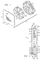
- FIGURE 1 is a diagrammatic exploded perspective view of a cooling apparatus 10 which embodies the present invention.
- the cooling apparatus 10 includes a housing defined by two housing parts 12 and 13.
- the cooling apparatus 10 further includes a plurality of sector-shaped porous members disposed within the housing, two of which are identified at 17 and 18 in FIGURE 1.
- the housing parts 12-13 and the porous parts 17-18 are all described in more detail later.
- the cooling apparatus 10 also includes a phase change material, which is disposed in the voids within the porous members 17-18, and is thus not separately visible in FIGURE 1.
- the cooling apparatus 10 also includes three expansion accumulators, which are not depicted in FIGURE 1, but which will be described in more detail later.
- the housing parts 12 and 13 are each made of a thermally conductive material.
- the thermally conductive material of the housing parts 12 and 13 is selected to have a coefficient of thermal expansion which substantially matches that of a system or device which is to be cooled by the cooling apparatus 10.
- the housing parts 12 and 13 are each made of aluminum.
- other thermally conductive materials could alternatively be used, for example so that the housing has a coefficient of thermal expansion different from that of aluminum.
- the housing parts could alternatively be made of aluminum silicon carbide (AlSiC).
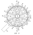
- FIGURE 2 is a side view of the cooling apparatus 10, in an assembled condition.
- FIGUREs 3 and 4 are diagrammatic sectional front and rear views of the cooling apparatus 10, respectively taken along the section lines 3-3 and 4-4 in FIGURE 2.
- FIGURE 3 is, in effect, a view of the cooling apparatus 10 without the housing part 13.
- the housing part 12 is a single solid piece of aluminum having approximately the shape of a disk.
- the housing part 12 has eight sector-shaped recesses 21-28, which are machined into a side thereof that faces the housing part 13.
- the recesses 21-28 do not open through the opposite side of the housing.
- a cylindrical hub portion 31 is disposed coaxially in the center of the disk-shaped housing part 12, with the recesses 21-28 distributed circumferentially around the hub 31 at uniformly spaced intervals.
- the housing part 12 also has an annular rim portion 32 which extends circumferentially around the outside of the recesses 21-28.
- the housing part 12 further has eight ribs 41-48, which each extend radially outwardly from the hub 31 to the rim portion 32 between a respective pair of the recesses 21-28.
- Each of the ribs 41-48 has two grooves or channels 52-53, which are provided at opposite ends of the rib on the side thereof facing the housing part 13.
- the channels 52-53 provide fluid communication between a respective pair of the recesses 21-28, which are disposed on opposite sides of that particular rib.
- the groove 52 is provided in each rib at the radial end thereof adjacent the hub 31, and the groove 53 is provided in each rib at the radial end thereof adjacent the rim portion 32.
- the recesses 21-28 and the grooves 52-53 collectively define a chamber within the housing.
- rim portion 32 On the inner side of the rim portion 32, on diametrically opposite sides of the housing part 12, are two inwardly projecting, semi-cylindrical ridges, which each have therein an axially extending opening that receives a respective alignment pin 56 or 57.
- the alignment pins 56 and 57 are provided on the housing part 13, as described later.
- the outer side of the rim portion 32 On the outer side of the rim portion 32 are eight radially outwardly extending projections 61-68, each circumferentially aligned with a respective one of the ribs 41-48.
- the outer side of the rim portion 32 also has three outwardly-projecting bosses 72-74, the boss 72 being disposed between the projections 62 and 63, the boss 73 being disposed between the projections 64 and 65, and the boss 74 being disposed between the projections 66 and 67.
- the bosses 72-74 each have thereon a respective outwardly facing flat surface 76-78.
- Two protrusions 81 and 82 project radially outwardly from the rim portion 32, and are disposed between the projections 61 and 68.
- the rim portion 32 has four radially outwardly projecting tabs 86-89, which are spaced circumferentially at uniform intervals, and which each have an axial opening therethrough.
- FIGURE 5 is a sectional side view taken along the line 5-5 in FIGURE 3.
- a central axial passageway 92 extends coaxially into the cylindrical hub 31 from a side of the housing part 12 opposite from the housing part 13.
- the passageway 92 extends to a location near the housing part 13, but does not open through the side of the housing part 12 which faces the housing part 13.
- Each of the radially-extending ribs 41-48 has extending therethrough a respective radial opening 101-108.
- the openings 101-108 each communicate at their radially inner end with the passageway 92, and each open through the a radially outer end of a respective one of the projections 61-68.
- a portion of each opening 101-108 which is within the associated projection 61-68 is of slightly greater diameter than the rest of that opening, and is internally threaded.
- a not-illustrated, threaded stud may be provided in the outer end of each of the openings 101-108, for example as shown at 112.
- the stud 112 is optional. The stud 112 is not present in the disclosed embodiment, and is therefore shown only in broken lines in FIGURE 4.
- three openings 116-118 each extend centrally through a respective one of the bosses 72-74, and also through the rim portion 32.
- the openings 116-118 each open through a respective one of the surfaces 76-78 provided at the outer ends of the bosses 72-74. Further, the openings 116-118 each open into a respective one of the recesses 23, 25 and 27, at a radially outer end of the recess.
- four threaded holes 121-124 are circumferentially distributed around each of the openings 116-118.
- the threaded holes 121-124 are blind holes, which do not communicate with the interior of the housing part 12.
- each of the protrusions 81-82 has a respective fill opening 127-128 extending radially therethrough, each of the fill openings 127-128 communicating at its radially inner end with the recess 21 in the housing part, and opening at its radially outer end through a surface on the radially outer end of the associated protrusion 81 or 82.
- the fill openings 127 and 128 are threaded, so that they may each be sealed by an appropriate bolt or stud, which is not illustrated. Alternatively, they may each be sealed by a press-in plug of a type known to those skilled in the art.
- the recesses 21, 23-25 and 27-28 each have therein a respective one of the sector-shaped porous members 17, and the recesses 22 and 26 each have therein a respective one of the sector-shaped porous members 18.
- the only difference between the porous members 17 and 18 is that the porous members 17 each have in the radially outer surface thereof a transverse groove 132 which is wide and shallow.
- the porous members 17 and 18 are each made from an aluminum foam.
- the effective volume occupied by each of the porous members 17 and 18 is 15% aluminum, and 85% void.
- a suitable material for the porous members 17 and 18 is commercially available from ERG Materials and Aerospace Corporation, Oakland, California, under the tradename DUOCEL.
- the porous members 17 and 18 are each of a size such that all outer surfaces thereof are in engagement with either the housing part 12 or the housing part 13, except that surfaces within the grooves 132 of the porous members 17 do not engage either of the housing parts.
- the housing part 13 is an aluminum plate.
- a plurality of openings 133 extend transversely through the housing part 13 at spaced locations along the peripheral edge thereof.
- the housing part 13 includes the two above-mentioned alignment pins 56 and 57, which are disposed near opposite sides of the aluminum plate 13, which each have one end fixedly mounted in the plate 13, and which each project toward the housing part 12.
- the pins 56 and 57 each extend into a respective opening provided in the ridges on the inner surfaces of the rim portion 32 of the housing part 12.
- the housing parts 12 and 13 are vacuum brazed to each other, in order to sealingly secure the housing parts to each other.
- the pins 56 and 57 keep the housing parts 12 and 13 in alignment until they have been brazed to each other.
- outer surfaces of each of the porous members 17 and 18 are brazed to surfaces of the housing, including surfaces on the metal plate 13, surfaces on the radially ribs 41-48, and the back surface of each of the recesses 21-28.
- Each of the radial openings 101-108 has therein a respective heat pipe, one of which is shown at 141 in FIGURE 4.
- Suitable heat pipes 141 are commercially available, one suitable example of which is the heat pipes commercially available from Dynatherm Corporation of Hunt Valley, Maryland, as Dynatherm 0476-1000.
- the heat pipes 141 in the disclosed embodiment each have a casing made of aluminum, and are filled with ammonia or pentane.
- FIGURE 4 has broken lines which show the heat pipe 141 in its inserted position.
- the radially outer end of the heat pipe 141 is crimped at 142.
- the crimp 142 is an inherent part of the structure of the heat pipe 141 which is created during its manufacture, in particular to seal the heat pipe 141 after it has been filled.
- Each of the ribs 41-48 in the disclosed embodiment has one radial opening 101-108 therethrough, and has one heat pipe 141 in the radial opening.
- more than one radially opening and heat pipe could be provided in each of the ribs 41-48.
- each of the heat pipes 141 is secured in place within the associated opening 101-108 by a thermally conductive epoxy adhesive, which is not illustrated.
- the thermally conductive adhesive facilitates heat transfer between the casing of the heat pipe 141, and the associated aluminum rib 41-48 within which the heat pipe is disposed.
- a suitable thermally conductive epoxy adhesive is a non-degassing or low degassing epoxy, such as MIL-A-46146 RTV coating available commercially from Dow Corning Corporation of Midland, Michigan.
- thermal grease for the thermally conductive epoxy.
- a suitable thermal grease is commercially available from Wakefield Engineering of Beverly, Massachusetts, as Wakefield 120 thermal grease.
- a thermal grease may have a tendency to flow or to evaporate. Therefore, the disclosed embodiment uses a thermally conductive epoxy adhesive, rather than a thermal grease.
- a thermal grease may be satisfactory, because it has the advantage of permitting the heat pipes 141 to be extracted.
- a respective threaded stud 112 would each be screwed into the outer end of each of the openings 101-108, in order to maintain the associated heat pipe 141 and its thermal grease in proper position.
- the passageway 92 in the hub 31 of the housing part 12 permits air to escape from each of the openings 101-108 as the associated heat pipe 141 is inserted therein.
- the epoxy adhesive essentially establishes an airtight seal around the heat pipe 141 and, in the absence of the passageway 92, air at the inner end of each of the openings 101-108 would be trapped and compressed, and would thus tend to urge the heat pipe 141 radially outwardly, much like the piston of a hydraulic cylinder.
- Passageway 92 permits air to escape from the openings 101-108, in order to avoid this problem. Once the heatpipes 141 have been installed, the passageway 92 is sealed in an appropriate manner.
- the passageway 92 may be threaded, and a threaded stud (not illustrated) may be introduced into the passageway 92.
- a press-in plug of a type known to persons in the art may be inserted into the passageway 92.
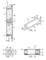
- FIGUREs 6-8 show an expansion accumulator 151, which is a commercially available device.
- the expansion accumulator 151 which is used in the disclosed embodiment may be obtained from EG&G of Daytona Beach, Florida, as part number 59450.
- the expansion accumulator 151 includes a rectangular plate 152, and a cylindrical tube 153 which extends perpendicular to and is secured to one side of the plate 152.
- Plate 152 has a central opening 156 therethrough, which communicates with the interior of the tube 153.
- the plate 152 has on a side thereof opposite from the tube 153 an annular groove 157, which extends concentrically around the opening 156.
- the groove 157 has therein a standard O-ring of silicon rubber, which has been omitted from FIGUREs 7 and 8 for purposes of clarity.
- the plate 152 has four holes 161-164 therethrough, which are provided at circumferentially spaced locations around the opening 156.
- the tube 153 includes at its end remote from the plate 152 a radially inwardly projecting annular flange 167.
- the expansion accumulator 151 includes, within the tube 153, a tubular bellows 168 which has one end sealingly coupled to the flange 167.
- a disk 169 is sealingly coupled to the opposite end of the bellows 168, and can move axially within the tube 153. The bellows expands and contracts as the disk 169 moves axially within the tube 153.
- FIGURE 3 has broken lines showing how one of the expansion accumulators 151 is coupled to the boss 73.
- the plate 152 is disposed adjacent to the surface 77 on the boss 73.
- Four not-illustrated screws each extend through a respective one of the holes 161-164 in the plate, and threadedly engage a respective one of the threaded holes 121-124 provided in the boss 73.
- the not-illustrated O-ring provided in the annular groove 157 engages the surface 77 on the boss 73, in order to create a seal between the accumulator 151 and the housing part 12.
- the other two expansion accumulators 151 are secured to the bosses 72 and 74 in a similar manner.
- the housing 12-13 has therein a phase change material of a known type. More specifically, following assembly of the various components of the apparatus 10 which have been described above, the phase change material is introduced into the housing in a generally fluid form, through the fill openings 127 and 128 which are provided in the protrusions 81 and 82 of FIGURE 2. As mentioned above, the recesses 21-28 and the channels 52-53 define a chamber within the housing, and about 15% of the overall space in the chamber is occupied by material of the porous members 17-18.
- phase change material As the phase change material is introduced through one or both of the fill openings 127-128, it flows through the recesses 21-28 and the channels 52-53, until it fills substantially all of the space within the recesses and channels other than that already occupied by the porous members 17-18. As this occurs, air from within the chamber escapes through the openings 127 and 128 as it is displaced by the phase change material. When substantially all of the air within the chamber has been replaced with a phase change material, the openings 127 and 128 are sealed, for example by inserting an appropriate threaded stud or screw.
- phase change material readily absorbs heat, but is not itself a good thermal conductor. Accordingly, the aluminum foam facilitates the distribution of heat within the phase change material disposed in the chamber of the housing. Suitable phase change materials are commercially available.
- the phase change material is n-Dotriacontane (A-32-99), which includes C 16 H 34 , and can be commercially obtained from Humphrey Chemical Company of North Haven, Connecticut.
- FIGUREs 9 and 10 are diagrammatic exploded perspective views of an antenna system 179 which includes two cooling systems of the type disclosed at 10 in FIGUREs 1-8 and discussed above. More specifically, the antenna system 179 includes two housing parts 181 and 182, which are each similar in structure to the housing part 12. Further, the antenna system 179 has a single plate 183, which is disposed between and brazed to each of the housing parts 181-182, and which corresponds to the housing part 13 in the embodiment of FIGUREs 1-8. A first set of porous members 186 is provided in the housing part 181, and a second set of porous members 187 is provided in the housing part 182.
- a phased array antenna system 189 is mounted on the side of the housing part 181 opposite from the housing part 182.
- the antenna 189 includes a plurality of antenna elements, as well as not-illustrated circuit components that cooperate electrically with the antenna elements.
- the not-illustrated circuit components may include miniature microwave integrated circuits (MMICs), which generate a substantial amount of heat during operation.
- MMICs miniature microwave integrated circuits
- the dual cooling systems shown in FIGUREs 9-10 are provided to absorb that heat during operation of the antenna system 179. For purposes of clarity, FIGUREs 9 and 10 do not show all of the components of the two dual cooling systems. However, aside from the fact that a common plate 183 is shared between the two cooling systems, each of the cooling system may be effectively equivalent to the cooling apparatus 10 disclosed above in association with FIGUREs 1-8.
- the operation of the cooling apparatus 10 of FIGUREs 1-8 is as follows. Heat is introduced into the cooling apparatus 10, typically by applying the heat to the surface of housing part 13 which is opposite from the housing part 12, or the surface of housing part 12 opposite from the housing part 13. Since the housing parts 12 and 13 are brazed to each other and to the porous members 17-18, and since these parts are all made of aluminum, the heat will tend to distribute itself within these parts.
- the heat pipes within the ribs 41-48 help facilitate a relatively uniform distribution of heat along each of the ribs.
- the phase change material within the housing absorbs the heat.
- the phase change material absorbs heat, but is not itself a particularly good thermal conductor.
- the porous members 17-18 facilitate distribution of heat throughout the phase change material, without requiring the heat to flow too far through the phase change material itself. As the phase change material absorbs heat, it changes phase.
- the cooling apparatus 10 is intended for use in applications where heat is generated by the antenna system at intermittent intervals.
- an antenna system cooled by the cooling apparatus 10 may only be able to operate during selected portions of the orbit, namely portions during which the antenna has a reasonably straight line of communication to a ground station.
- the antenna system generates heat which is absorbed by the cooling apparatus 10
- the antenna system is idle and the cooling apparatus 10 slowly discharges the heat which it previously absorbed.
- the cooling apparatus 10 is designed so that there should be little or no significant volumetric expansion to the phase change material under expected operating conditions. However, in unusual circumstances, it may be necessary for the cooling apparatus 10 to absorb more heat than it was normally designed to absorb. This is the reason why the three accumulators 151 are provided. In particular, if the cooling apparatus 10 absorbs sufficient heat that the phase change material begins to significantly expand in volume, then the phase change material can flow into the accumulators 151, in particular by pressing the disk 169 of each accumulator 151 radially outwardly, causing the associated tubular bellows 168 to compress. This avoids damage to the cooling apparatus 10, by avoiding a buildup of internal pressure. When the cooling apparatus 10 does eventually cool back down, the phase change material which flowed into the accumulators 151 will be urged back into the housing by the resilient forces of the tubular bellows 168.
- the porous members 17 in the recesses 21, 23, 25 and 27 each have therein a groove 132.
- the grooves 132 in these porous members facilitate flow of the phase change material through the openings 116-118, and through the fill openings 127-128.
- the porous members 17 in recesses 24 and 28 also have the grooves 132, but for the purpose of accommodating the semi-cylindrical ridges which are provided on the inner surface of the rim portion 32 of the housing.
- the porous members 18 in the recesses 22 and 26 do not have the grooves 132. This is to maximize the surface area of the porous members 18 which is in contact with the rim portion 32 of the housing part 12, and with the phase change material, in order to facilitate heat distribution within the housing and the phase change material.
- the present invention provides a number of technical advantages.
- thermal gradients across the region cooled by the disclosed cooling system are minimized by structural features such as heat pipes.
- the reduction in thermal gradients provides a reduction in phase errors in radio frequency signals within the antenna system, so that no dynamic phase compensation is required in the circuitry itself, which in turn reduces the complexity and cost of the circuitry of the antenna system.
- the disclosed cooling system is compact and light in weight, and therefore highly suitable for use in applications such as a satellite, yet provides better cooling than previously known satellite cooling systems of comparable size and weight.
- the disclosed cooling apparatus can be positioned on the back side of a phased array antenna system, thus permitting the thermal design of the cooling system to be optimized independently of the electrical and radio frequency design of the antenna system.
- the cooling apparatus is capable of cooling a higher level of heat dissipation than comparable preexisting systems, thereby avoiding excessive junction temperatures in cooled circuit devices, which in turn results in reduced failures and higher reliability of electrical components.
- the radial ribs each include one heat pipe, but it would be possible to provide more heat pipes in each rib.
- the heat pipes and their associated ribs are arranged to extend radially in the disclosed embodiment, but it would be possible to provide some other configuration of ribs and/or heat pipes.
- the heat pipes in the disclosed embodiment are provided within ribs, but it would be possible to incorporate them into the housing in some other manner.
- the chamber inside the disclosed housing is configured in the form of several portions or recesses which are substantially separate and communicate with each other through several channels, but the housing could be configured so that the ribs extend within the chamber without dividing it into substantially separate portions.
- the disclosed embodiment includes several expansion accumulators, but it would be possible use a different type of device to accommodate expansion, or to omit the expansion accumulators for certain applications.
Landscapes
- Engineering & Computer Science (AREA)
- Thermal Sciences (AREA)
- Physics & Mathematics (AREA)
- General Engineering & Computer Science (AREA)
- Mechanical Engineering (AREA)
- Life Sciences & Earth Sciences (AREA)
- General Health & Medical Sciences (AREA)
- Biodiversity & Conservation Biology (AREA)
- Remote Sensing (AREA)
- Aviation & Aerospace Engineering (AREA)
- Health & Medical Sciences (AREA)
- Environmental Sciences (AREA)
- Environmental & Geological Engineering (AREA)
- Toxicology (AREA)
- Chemical & Material Sciences (AREA)
- Dispersion Chemistry (AREA)
- Microelectronics & Electronic Packaging (AREA)
- Sustainable Development (AREA)
- Cooling Or The Like Of Electrical Apparatus (AREA)
- Variable-Direction Aerials And Aerial Arrays (AREA)
- Cooling Or The Like Of Semiconductors Or Solid State Devices (AREA)
Description
- This invention relates in general to a cooling apparatus and, more particularly, to a cooling apparatus containing a phase change material and suitable for use with a phased array antenna system.
- Phased array antenna systems are frequently used in satellites, for example to provide communication between a satellite and a ground station on the earth. As the satellite goes through its orbit, there are portions of the orbit in which the satellite antenna system can communicate with the ground station, and portions of the orbit in which the curvature of the earth prevents such communication. Consequently, the antenna system is operated during portions of the orbit, and is not operated during other portions of the orbit.
- State of the art designs for phased array antenna systems include the use of miniature microwave integrated circuits (MMICs), positioned in close proximity to the antenna elements. The close proximity of the MMICs and antenna elements helps to reduce phase delays in radio frequency signals within the antenna system. On the other hand, the MMIC components generate a substantial amount of heat. If not properly cooled, this can interfere with antenna operation. In particular, temperature gradients across the antenna array must be minimized, because significant temperature gradients introduce phase errors into electrical radio frequency signals within the antenna system, which in turn leads to errors and/or inaccuracies during antenna operation.
- In this regard, the maximum allowable temperature gradient across the array decreases as the operating speed of the array is increased. For example, when the phased array is operating at a frequency of about 5 GHz, the maximum allowable temperature gradient across the array is about 20°C. In contrast, when the array is operating at a frequency of about 80 GHz, the maximum allowable temperature gradient across the array is only about 1.3°C. If the maximum temperature gradient across the array cannot be kept within the appropriate limit, then it is necessary to provide additional circuitry in the antenna system, in order to effect dynamic phase error compensation control. Of course, this additional compensation circuitry increases the complexity, cost and weight of the phased array. Thus, it is desirable to have a cooling apparatus which is both efficient and effective.
- Providing such a cooling apparatus in the specific environment of a satellite involves some relative stringent design criteria. The cooling apparatus must be relatively compact, and light in weight. Further, it must be highly reliable, and relatively maintenance free. One prior approach was to provide a cooling apparatus which included a housing with a chamber therein, the chamber containing both a phase change material and a thermally conductive porous material. Although such a cooling apparatus has been generally adequate for its intended purpose, it has not been satisfactory in all respects.
- More specifically, it is not always possible to achieve cooling of a level sufficient to keep temperature gradients across the surface of an antenna system within a desired limit, particularly as operating frequencies increase. As a result, and as mentioned above, it can be necessary to provide special additional circuitry in the antenna system in order to effect dynamic phase compensation, thereby increasing the complexity, cost and weight of the antenna system. Further, with respect to antenna systems that are either large and/or high-power systems, the known cooling apparatus is not always capable of providing sufficiently efficient cooling to maintain junctions of the electrical devices at temperatures which are low enough to assure accurate and reliable operation. One result is a reduction in the accuracy and/or reliability of the overall antenna system. An example of a prior art cooling system using a phase change material and heat pipes can be found in US 5386701.
- From the foregoing, it may be appreciated that a need has arisen for a method and apparatus for providing effective and efficient cooling, with a cooling apparatus which is compact, lightweight and reliable, and which can consistently and accurately minimize temperature gradients across a device that is being cooled, while providing a greater cooling capacity than preexisting cooling devices. According to the present invention, a method and apparatus are provided to address this need, and involve: transferring heat to a housing which has therein a chamber that contains a heat absorbing material, the heat absorbing material including a porous material and a phase changing material; distributing the heat within the heat absorbing material, including use of a heat pipe within the housing to facilitate distribution of the heat; and causing the heat absorbing material to absorb the heat.
- A better understanding of the present invention will be realized from the detailed description which follows, taken in conjunction with the accompanying drawings, in which:
- FIGURE 1 is a diagrammatic exploded perspective view of a cooling apparatus which embodies the present invention;
- FIGURE 2 is a diagrammatic side view of the cooling apparatus of FIGURE 1, in a non-exploded configuration;
- FIGURE 3 is a sectional front view of the cooling apparatus, taken along the line 3-3 in FIGURE 2;
- FIGURE 4 is a sectional rear view of the cooling apparatus, taken along the line 4-4 in FIGURE 2;
- FIGURE 5 is a sectional side view of the cooling apparatus, taken along the line 5-5 in FIGURE 3;
- FIGURE 6 is a perspective view of an expansion accumulator which is a component of the cooling apparatus of FIGUREs 1-5;
- FIGURE 7 is an end view of the expansion accumulator of FIGURE 6;
- FIGURE 8 is a diagrammatic sectional side view of the expansion accumulator of FIGURE 6, taken along the line 8-8 in FIGURE 6;
- FIGURE 9 is a diagrammatic exploded perspective view of the front of an antenna system which includes the cooling apparatus of FIGUREs 1-8; and
- FIGURE 10 is a diagrammatic exploded perspective view of the rear of the antenna system of FIGURE 9.
- FIGURE 1 is a diagrammatic exploded perspective view of a
cooling apparatus 10 which embodies the present invention. Thecooling apparatus 10 includes a housing defined by twohousing parts cooling apparatus 10 further includes a plurality of sector-shaped porous members disposed within the housing, two of which are identified at 17 and 18 in FIGURE 1. The housing parts 12-13 and the porous parts 17-18 are all described in more detail later. Thecooling apparatus 10 also includes a phase change material, which is disposed in the voids within the porous members 17-18, and is thus not separately visible in FIGURE 1. Thecooling apparatus 10 also includes three expansion accumulators, which are not depicted in FIGURE 1, but which will be described in more detail later. - In the disclosed embodiment, the
housing parts housing parts cooling apparatus 10. In the disclosed embodiment, thehousing parts - FIGURE 2 is a side view of the
cooling apparatus 10, in an assembled condition. FIGUREs 3 and 4 are diagrammatic sectional front and rear views of thecooling apparatus 10, respectively taken along the section lines 3-3 and 4-4 in FIGURE 2. FIGURE 3 is, in effect, a view of thecooling apparatus 10 without thehousing part 13. - Referring to FIGURE 3, the
housing part 12 is a single solid piece of aluminum having approximately the shape of a disk. Thehousing part 12 has eight sector-shaped recesses 21-28, which are machined into a side thereof that faces thehousing part 13. The recesses 21-28 do not open through the opposite side of the housing. Acylindrical hub portion 31 is disposed coaxially in the center of the disk-shaped housing part 12, with the recesses 21-28 distributed circumferentially around thehub 31 at uniformly spaced intervals. Thehousing part 12 also has anannular rim portion 32 which extends circumferentially around the outside of the recesses 21-28. Thehousing part 12 further has eight ribs 41-48, which each extend radially outwardly from thehub 31 to therim portion 32 between a respective pair of the recesses 21-28. Each of the ribs 41-48 has two grooves or channels 52-53, which are provided at opposite ends of the rib on the side thereof facing thehousing part 13. The channels 52-53 provide fluid communication between a respective pair of the recesses 21-28, which are disposed on opposite sides of that particular rib. Thegroove 52 is provided in each rib at the radial end thereof adjacent thehub 31, and thegroove 53 is provided in each rib at the radial end thereof adjacent therim portion 32. The recesses 21-28 and the grooves 52-53 collectively define a chamber within the housing. - On the inner side of the
rim portion 32, on diametrically opposite sides of thehousing part 12, are two inwardly projecting, semi-cylindrical ridges, which each have therein an axially extending opening that receives arespective alignment pin housing part 13, as described later. - On the outer side of the
rim portion 32 are eight radially outwardly extending projections 61-68, each circumferentially aligned with a respective one of the ribs 41-48. The outer side of therim portion 32 also has three outwardly-projecting bosses 72-74, theboss 72 being disposed between theprojections boss 73 being disposed between theprojections boss 74 being disposed between theprojections protrusions rim portion 32, and are disposed between theprojections rim portion 32 has four radially outwardly projecting tabs 86-89, which are spaced circumferentially at uniform intervals, and which each have an axial opening therethrough. - FIGURE 5 is a sectional side view taken along the line 5-5 in FIGURE 3. Referring to FIGUREs 4 and 5, a central
axial passageway 92 extends coaxially into thecylindrical hub 31 from a side of thehousing part 12 opposite from thehousing part 13. Thepassageway 92 extends to a location near thehousing part 13, but does not open through the side of thehousing part 12 which faces thehousing part 13. - Each of the radially-extending ribs 41-48 has extending therethrough a respective radial opening 101-108. The openings 101-108 each communicate at their radially inner end with the
passageway 92, and each open through the a radially outer end of a respective one of the projections 61-68. A portion of each opening 101-108 which is within the associated projection 61-68 is of slightly greater diameter than the rest of that opening, and is internally threaded. A not-illustrated, threaded stud may be provided in the outer end of each of the openings 101-108, for example as shown at 112. However, thestud 112 is optional. Thestud 112 is not present in the disclosed embodiment, and is therefore shown only in broken lines in FIGURE 4. - With reference to FIGUREs 2 and 4, three openings 116-118 each extend centrally through a respective one of the bosses 72-74, and also through the
rim portion 32. The openings 116-118 each open through a respective one of the surfaces 76-78 provided at the outer ends of the bosses 72-74. Further, the openings 116-118 each open into a respective one of therecesses housing part 12. As best seen in FIGURE 2, each of the protrusions 81-82 has a respective fill opening 127-128 extending radially therethrough, each of the fill openings 127-128 communicating at its radially inner end with therecess 21 in the housing part, and opening at its radially outer end through a surface on the radially outer end of the associatedprotrusion fill openings - With reference to FIGURE 3, the
recesses 21, 23-25 and 27-28 each have therein a respective one of the sector-shapedporous members 17, and therecesses porous members 18. The only difference between theporous members porous members 17 each have in the radially outer surface thereof atransverse groove 132 which is wide and shallow. As mentioned above, theporous members porous members porous members porous members housing part 12 or thehousing part 13, except that surfaces within thegrooves 132 of theporous members 17 do not engage either of the housing parts. - As best seen in FIGUREs 1 and 4, the
housing part 13 is an aluminum plate. A plurality ofopenings 133 extend transversely through thehousing part 13 at spaced locations along the peripheral edge thereof. Further, thehousing part 13 includes the two above-mentioned alignment pins 56 and 57, which are disposed near opposite sides of thealuminum plate 13, which each have one end fixedly mounted in theplate 13, and which each project toward thehousing part 12. In particular, as best seen in FIGUREs 3 and 5, thepins rim portion 32 of thehousing part 12. In the disclosed embodiment, thehousing parts pins housing parts porous members metal plate 13, surfaces on the radially ribs 41-48, and the back surface of each of the recesses 21-28. - Each of the radial openings 101-108 has therein a respective heat pipe, one of which is shown at 141 in FIGURE 4.
Suitable heat pipes 141 are commercially available, one suitable example of which is the heat pipes commercially available from Dynatherm Corporation of Hunt Valley, Maryland, as Dynatherm 0476-1000. Theheat pipes 141 in the disclosed embodiment each have a casing made of aluminum, and are filled with ammonia or pentane. FIGURE 4 has broken lines which show theheat pipe 141 in its inserted position. The radially outer end of theheat pipe 141 is crimped at 142. Thecrimp 142 is an inherent part of the structure of theheat pipe 141 which is created during its manufacture, in particular to seal theheat pipe 141 after it has been filled. - Each of the ribs 41-48 in the disclosed embodiment has one radial opening 101-108 therethrough, and has one
heat pipe 141 in the radial opening. However, it will be recognized that more than one radially opening and heat pipe could be provided in each of the ribs 41-48. - In the disclosed embodiment, each of the
heat pipes 141 is secured in place within the associated opening 101-108 by a thermally conductive epoxy adhesive, which is not illustrated. In addition to holding theheat pipe 141 in place, the thermally conductive adhesive facilitates heat transfer between the casing of theheat pipe 141, and the associated aluminum rib 41-48 within which the heat pipe is disposed. For purposes of the disclosed embodiment, a suitable thermally conductive epoxy adhesive is a non-degassing or low degassing epoxy, such as MIL-A-46146 RTV coating available commercially from Dow Corning Corporation of Midland, Michigan. - It is alternatively possible to substitute a known thermal grease for the thermally conductive epoxy. A suitable thermal grease is commercially available from Wakefield Engineering of Beverly, Massachusetts, as Wakefield 120 thermal grease. In certain applications, for example in the vacuum of outer space, a thermal grease may have a tendency to flow or to evaporate. Therefore, the disclosed embodiment uses a thermally conductive epoxy adhesive, rather than a thermal grease. However, for some applications, a thermal grease may be satisfactory, because it has the advantage of permitting the
heat pipes 141 to be extracted. In the event that a thermal grease is used instead of a thermally conductive epoxy adhesive, a respective threadedstud 112 would each be screwed into the outer end of each of the openings 101-108, in order to maintain the associatedheat pipe 141 and its thermal grease in proper position. - The
passageway 92 in thehub 31 of thehousing part 12 permits air to escape from each of the openings 101-108 as the associatedheat pipe 141 is inserted therein. The epoxy adhesive essentially establishes an airtight seal around theheat pipe 141 and, in the absence of thepassageway 92, air at the inner end of each of the openings 101-108 would be trapped and compressed, and would thus tend to urge theheat pipe 141 radially outwardly, much like the piston of a hydraulic cylinder.Passageway 92 permits air to escape from the openings 101-108, in order to avoid this problem. Once theheatpipes 141 have been installed, thepassageway 92 is sealed in an appropriate manner. For example, thepassageway 92 may be threaded, and a threaded stud (not illustrated) may be introduced into thepassageway 92. Alternatively, a press-in plug of a type known to persons in the art may be inserted into thepassageway 92. - FIGUREs 6-8 show an
expansion accumulator 151, which is a commercially available device. Theexpansion accumulator 151 which is used in the disclosed embodiment may be obtained from EG&G of Daytona Beach, Florida, as part number 59450. Theexpansion accumulator 151 includes arectangular plate 152, and acylindrical tube 153 which extends perpendicular to and is secured to one side of theplate 152.Plate 152 has acentral opening 156 therethrough, which communicates with the interior of thetube 153. Theplate 152 has on a side thereof opposite from thetube 153 anannular groove 157, which extends concentrically around theopening 156. Thegroove 157 has therein a standard O-ring of silicon rubber, which has been omitted from FIGUREs 7 and 8 for purposes of clarity. Theplate 152 has four holes 161-164 therethrough, which are provided at circumferentially spaced locations around theopening 156. - With reference to FIGUREs 6 and 8, the
tube 153 includes at its end remote from the plate 152 a radially inwardly projectingannular flange 167. Theexpansion accumulator 151 includes, within thetube 153, a tubular bellows 168 which has one end sealingly coupled to theflange 167. Adisk 169 is sealingly coupled to the opposite end of thebellows 168, and can move axially within thetube 153. The bellows expands and contracts as thedisk 169 moves axially within thetube 153. - Three of the
expansion accumulators 151 are secured to thehousing part 12. In more detail, FIGURE 3 has broken lines showing how one of theexpansion accumulators 151 is coupled to theboss 73. In this regard, theplate 152 is disposed adjacent to thesurface 77 on theboss 73. Four not-illustrated screws each extend through a respective one of the holes 161-164 in the plate, and threadedly engage a respective one of the threaded holes 121-124 provided in theboss 73. (FIGURE 2). The not-illustrated O-ring provided in theannular groove 157 engages thesurface 77 on theboss 73, in order to create a seal between theaccumulator 151 and thehousing part 12. The other twoexpansion accumulators 151 are secured to thebosses - As mentioned above, the housing 12-13 has therein a phase change material of a known type. More specifically, following assembly of the various components of the
apparatus 10 which have been described above, the phase change material is introduced into the housing in a generally fluid form, through thefill openings protrusions openings openings - The phase change material readily absorbs heat, but is not itself a good thermal conductor. Accordingly, the aluminum foam facilitates the distribution of heat within the phase change material disposed in the chamber of the housing. Suitable phase change materials are commercially available. In the disclosed embodiment, the phase change material is n-Dotriacontane (A-32-99), which includes C16H34, and can be commercially obtained from Humphrey Chemical Company of North Haven, Connecticut.
- FIGUREs 9 and 10 are diagrammatic exploded perspective views of an
antenna system 179 which includes two cooling systems of the type disclosed at 10 in FIGUREs 1-8 and discussed above. More specifically, theantenna system 179 includes twohousing parts housing part 12. Further, theantenna system 179 has asingle plate 183, which is disposed between and brazed to each of the housing parts 181-182, and which corresponds to thehousing part 13 in the embodiment of FIGUREs 1-8. A first set ofporous members 186 is provided in thehousing part 181, and a second set ofporous members 187 is provided in thehousing part 182. Aside from the fact that theplate 183 is shared between these two cooling systems, the cooling systems may each be effectively equivalent to thecooling apparatus 10 described above in association with FIGUREs 1-8. A phasedarray antenna system 189 is mounted on the side of thehousing part 181 opposite from thehousing part 182. Theantenna 189 includes a plurality of antenna elements, as well as not-illustrated circuit components that cooperate electrically with the antenna elements. The not-illustrated circuit components may include miniature microwave integrated circuits (MMICs), which generate a substantial amount of heat during operation. The dual cooling systems shown in FIGUREs 9-10 are provided to absorb that heat during operation of theantenna system 179. For purposes of clarity, FIGUREs 9 and 10 do not show all of the components of the two dual cooling systems. However, aside from the fact that acommon plate 183 is shared between the two cooling systems, each of the cooling system may be effectively equivalent to thecooling apparatus 10 disclosed above in association with FIGUREs 1-8. - The operation of the
cooling apparatus 10 of FIGUREs 1-8 is as follows. Heat is introduced into thecooling apparatus 10, typically by applying the heat to the surface ofhousing part 13 which is opposite from thehousing part 12, or the surface ofhousing part 12 opposite from thehousing part 13. Since thehousing parts - Due to contact with the
housing parts - The
cooling apparatus 10 is intended for use in applications where heat is generated by the antenna system at intermittent intervals. For example, in a satellite, an antenna system cooled by thecooling apparatus 10 may only be able to operate during selected portions of the orbit, namely portions during which the antenna has a reasonably straight line of communication to a ground station. Thus, during certain portions of the orbit the antenna system generates heat which is absorbed by thecooling apparatus 10, and during other portions of the orbit, the antenna system is idle and thecooling apparatus 10 slowly discharges the heat which it previously absorbed. - If the phase change material continues to absorb heat after it changes phase, it will eventually begin to expand in volume. The
cooling apparatus 10 is designed so that there should be little or no significant volumetric expansion to the phase change material under expected operating conditions. However, in unusual circumstances, it may be necessary for thecooling apparatus 10 to absorb more heat than it was normally designed to absorb. This is the reason why the threeaccumulators 151 are provided. In particular, if thecooling apparatus 10 absorbs sufficient heat that the phase change material begins to significantly expand in volume, then the phase change material can flow into theaccumulators 151, in particular by pressing thedisk 169 of eachaccumulator 151 radially outwardly, causing the associated tubular bellows 168 to compress. This avoids damage to thecooling apparatus 10, by avoiding a buildup of internal pressure. When thecooling apparatus 10 does eventually cool back down, the phase change material which flowed into theaccumulators 151 will be urged back into the housing by the resilient forces of the tubular bellows 168. - Referring to FIGURE 4, and as mentioned above, the
porous members 17 in therecesses groove 132. Thegrooves 132 in these porous members facilitate flow of the phase change material through the openings 116-118, and through the fill openings 127-128. Theporous members 17 inrecesses grooves 132, but for the purpose of accommodating the semi-cylindrical ridges which are provided on the inner surface of therim portion 32 of the housing. Theporous members 18 in therecesses grooves 132. This is to maximize the surface area of theporous members 18 which is in contact with therim portion 32 of thehousing part 12, and with the phase change material, in order to facilitate heat distribution within the housing and the phase change material. - The present invention provides a number of technical advantages. In particular, thermal gradients across the region cooled by the disclosed cooling system are minimized by structural features such as heat pipes. When the system is being used specifically to cool a phased array antenna system, the reduction in thermal gradients provides a reduction in phase errors in radio frequency signals within the antenna system, so that no dynamic phase compensation is required in the circuitry itself, which in turn reduces the complexity and cost of the circuitry of the antenna system. A further consideration is that the disclosed cooling system is compact and light in weight, and therefore highly suitable for use in applications such as a satellite, yet provides better cooling than previously known satellite cooling systems of comparable size and weight.
- Another advantage is that the disclosed cooling apparatus can be positioned on the back side of a phased array antenna system, thus permitting the thermal design of the cooling system to be optimized independently of the electrical and radio frequency design of the antenna system. Yet another advantage is that the cooling apparatus is capable of cooling a higher level of heat dissipation than comparable preexisting systems, thereby avoiding excessive junction temperatures in cooled circuit devices, which in turn results in reduced failures and higher reliability of electrical components.
- Although one embodiment has been illustrated and described in detail, it should be understood that various substitutions and alterations can be made therein without departing from the scope of the present invention. For example, in the disclosed embodiment, the radial ribs each include one heat pipe, but it would be possible to provide more heat pipes in each rib. A further example is that the heat pipes and their associated ribs are arranged to extend radially in the disclosed embodiment, but it would be possible to provide some other configuration of ribs and/or heat pipes. Yet another example is that the heat pipes in the disclosed embodiment are provided within ribs, but it would be possible to incorporate them into the housing in some other manner.
- Still another example is that the chamber inside the disclosed housing is configured in the form of several portions or recesses which are substantially separate and communicate with each other through several channels, but the housing could be configured so that the ribs extend within the chamber without dividing it into substantially separate portions. As yet another example, the disclosed embodiment includes several expansion accumulators, but it would be possible use a different type of device to accommodate expansion, or to omit the expansion accumulators for certain applications.
Claims (11)
- A cooling apparatus (10), comprising:a housing (12, 13) having a chamber (21-28) therein;a heat absorbing material disposed within said chamber in said housing, the heat absorbing material including a porous material (17, 18) and a phase changing material disposed within said chamber and said porous material (17, 18); anda heat pipe (141) disposed within said housing and operative to facilitate heat distribution within said heat absorbing material;including a plurality of further heat pipes (141);wherein said housing includes a plurality of thermally conductive ribs (41-48) extending within said chamber; andeach rib having therein an opening (101-108);wherein each said opening has therein a respective one of said heat pipes;wherein said chamber includes a plurality of portions which are substantially separated from each other by said ribs, andwherein said chamber includes a plurality of channels (52, 53) which are provided in said housing and which facilitate fluid communication between said portions of said chamber.
- An apparatus according to Claim 1, wherein said housing includes a thermally conductive first part having a plurality of recesses provided in one side thereof, each said portion of said chamber being in a respective one of said recesses; wherein said ribs are portions of said first part which are disposed between said recesses; wherein said housing further includes a thermally conductive second part which is disposed against said one side of said first part; and wherein said channels are each a transverse groove provided in a respective said rib on a side thereof adjacent said second part.
- An apparatus according to Claim 1, wherein said ribs extend radially in respective different directions; wherein said openings in said ribs extend radially; and wherein said portions of said chamber are each sector-shaped, and are each disposed between a respective pair of said ribs.
- An apparatus according Claim 1, including an expansion accumulator which is in fluid communication with said chamber, which receives a portion of said heat absorbing material from said chamber when said heat absorbing material expands in response to an increase in temperature, and which returns said portion of said heat absorbing material to said chamber when said heat absorbing material contracts in response to a decrease in temperature.
- An apparatus according to Claim 1, including in each said portion of said chamber a thermally conductive member made of a porous material.
- An apparatus according to Claim 5, wherein said housing and said thermally conductive members are all made of a metal, and wherein said thermally conductive members are each brazed to surfaces of said housing which define said chamber.
- An apparatus according to Claim 5, wherein said heat absorbing material is a phase change material.
- An apparatus according to Claim 1, including an antenna system which is coupled to said housing and which generates heat that is transferred to said housing.
- An apparatus according to Claim 1, wherein said heat absorbing material is a phase change material.
- An apparatus according to Claim 1, wherein each said opening has a first end which communicates through a passageway in said housing with a location external to said housing.
- An apparatus according to Claim 10, wherein each said opening has a second end which is remote from said first end and which opens outwardly through an outer surface of said housing.
Applications Claiming Priority (3)
| Application Number | Priority Date | Filing Date | Title |
|---|---|---|---|
| US09/397,481 US7069975B1 (en) | 1999-09-16 | 1999-09-16 | Method and apparatus for cooling with a phase change material and heat pipes |
| US397481 | 1999-09-16 | ||
| PCT/US2000/025297 WO2001020713A1 (en) | 1999-09-16 | 2000-09-14 | Method and apparatus for cooling with a phase change material and heat pipes |
Publications (2)
| Publication Number | Publication Date |
|---|---|
| EP1218965A1 EP1218965A1 (en) | 2002-07-03 |
| EP1218965B1 true EP1218965B1 (en) | 2007-01-24 |
Family
ID=23571372
Family Applications (1)
| Application Number | Title | Priority Date | Filing Date |
|---|---|---|---|
| EP00965034A Expired - Lifetime EP1218965B1 (en) | 1999-09-16 | 2000-09-14 | Apparatus for cooling with a phase change material and heat pipes |
Country Status (7)
| Country | Link |
|---|---|
| US (2) | US7069975B1 (en) |
| EP (1) | EP1218965B1 (en) |
| JP (1) | JP4357780B2 (en) |
| AU (1) | AU7582300A (en) |
| CA (1) | CA2383703C (en) |
| DE (1) | DE60033165T2 (en) |
| WO (1) | WO2001020713A1 (en) |
Cited By (1)
| Publication number | Priority date | Publication date | Assignee | Title |
|---|---|---|---|---|
| WO2020208365A1 (en) * | 2019-04-10 | 2020-10-15 | Mbda Uk Limited | Missile comprising electronics and a jumping-drop vapour chamber |
Families Citing this family (69)
| Publication number | Priority date | Publication date | Assignee | Title |
|---|---|---|---|---|
| SE0103040D0 (en) | 2001-09-13 | 2001-09-13 | Wahlberg & Selin Ab | Mobile satellite link terminal |
| WO2004057406A2 (en) * | 2002-12-23 | 2004-07-08 | Bae Systems Plc | Deformable-mirror cooling |
| US7106777B2 (en) * | 2003-01-07 | 2006-09-12 | The Boeing Company | Phase-change heat exchanger |
| IL173373A0 (en) * | 2006-01-26 | 2006-09-05 | Nuclear Res Ct Negev | Thermal energy storage apparatus |
| US7447029B2 (en) * | 2006-03-14 | 2008-11-04 | Fu Zhun Precision Industry (Shen Zhen) Co., Ltd. | Vapor chamber for dissipation heat generated by electronic component |
| BRPI0905987A2 (en) | 2008-02-22 | 2015-06-30 | Dow Global Technologies Inc | Thermal energy storage material system, method for manufacturing a thermal energy storage material system and use of a thermal energy storage material system |
| US20090321045A1 (en) * | 2008-06-30 | 2009-12-31 | Alcatel-Lucent Technologies Inc. | Monolithic structurally complex heat sink designs |
| EP2154462A1 (en) * | 2008-08-13 | 2010-02-17 | BAE Systems PLC | Latent heat storage body |
| EP2332839B1 (en) | 2008-10-02 | 2015-06-24 | Ibérica del Espacio, S.A. | Spaceship heat module |
| US8045329B2 (en) * | 2009-04-29 | 2011-10-25 | Raytheon Company | Thermal dissipation mechanism for an antenna |
| US8342454B1 (en) | 2009-06-29 | 2013-01-01 | Paragon Space Development Corporation | Cooling systems |
| US9395123B1 (en) | 2009-06-29 | 2016-07-19 | Paragon Space Development Corporation | Cooling systems |
| KR20110026193A (en) * | 2009-09-07 | 2011-03-15 | 삼성전자주식회사 | System for cooling heated member and sytem for cooling battery |
| US20110100583A1 (en) * | 2009-10-29 | 2011-05-05 | Freund Sebastian W | Reinforced thermal energy storage pressure vessel for an adiabatic compressed air energy storage system |
| BR112012017117A2 (en) * | 2010-01-29 | 2017-10-03 | Dow Global Technologies Llc | THERMAL ENERGY STORAGE ARTICLE |
| CN101792025B (en) * | 2010-04-07 | 2012-08-08 | 北京交通大学 | Driving device suitable for space environment |
| EP2568792A1 (en) * | 2011-09-06 | 2013-03-13 | ABB Research Ltd. | Apparatus |
| EP2568789B1 (en) | 2011-09-06 | 2014-04-16 | ABB Research Ltd. | Heat exchanger |
| US9223138B2 (en) | 2011-12-23 | 2015-12-29 | Microsoft Technology Licensing, Llc | Pixel opacity for augmented reality |
| US9606586B2 (en) | 2012-01-23 | 2017-03-28 | Microsoft Technology Licensing, Llc | Heat transfer device |
| US8934235B2 (en) * | 2012-01-23 | 2015-01-13 | Microsoft Corporation | Heat transfer device with phase change material |
| US9726887B2 (en) | 2012-02-15 | 2017-08-08 | Microsoft Technology Licensing, Llc | Imaging structure color conversion |
| US9297996B2 (en) | 2012-02-15 | 2016-03-29 | Microsoft Technology Licensing, Llc | Laser illumination scanning |
| US9779643B2 (en) | 2012-02-15 | 2017-10-03 | Microsoft Technology Licensing, Llc | Imaging structure emitter configurations |
| US9578318B2 (en) | 2012-03-14 | 2017-02-21 | Microsoft Technology Licensing, Llc | Imaging structure emitter calibration |
| US11068049B2 (en) | 2012-03-23 | 2021-07-20 | Microsoft Technology Licensing, Llc | Light guide display and field of view |
| US9558590B2 (en) | 2012-03-28 | 2017-01-31 | Microsoft Technology Licensing, Llc | Augmented reality light guide display |
| US10191515B2 (en) | 2012-03-28 | 2019-01-29 | Microsoft Technology Licensing, Llc | Mobile device light guide display |
| US9717981B2 (en) | 2012-04-05 | 2017-08-01 | Microsoft Technology Licensing, Llc | Augmented reality and physical games |
| WO2013169774A2 (en) | 2012-05-07 | 2013-11-14 | Phononic Devices, Inc. | Thermoelectric heat exchanger component including protective heat spreading lid and optimal thermal interface resistance |
| US20130291555A1 (en) | 2012-05-07 | 2013-11-07 | Phononic Devices, Inc. | Thermoelectric refrigeration system control scheme for high efficiency performance |
| US10502876B2 (en) | 2012-05-22 | 2019-12-10 | Microsoft Technology Licensing, Llc | Waveguide optics focus elements |
| US8989535B2 (en) | 2012-06-04 | 2015-03-24 | Microsoft Technology Licensing, Llc | Multiple waveguide imaging structure |
| US9311909B2 (en) | 2012-09-28 | 2016-04-12 | Microsoft Technology Licensing, Llc | Sensed sound level based fan speed adjustment |
| US10192358B2 (en) | 2012-12-20 | 2019-01-29 | Microsoft Technology Licensing, Llc | Auto-stereoscopic augmented reality display |
| US9296496B2 (en) * | 2013-03-04 | 2016-03-29 | Raytheon Company | Thermal management system and method for space and air-borne sensors |
| WO2014142902A1 (en) | 2013-03-14 | 2014-09-18 | The Crom Corporation | Spider diffuser system |
| JP2016516387A (en) * | 2013-03-15 | 2016-06-02 | フィンシックス コーポレイションFinsix Corporation | Method and apparatus for controlling heat in a power conversion system |
| CZ2013278A3 (en) * | 2013-04-11 | 2014-10-22 | Halla Visteon Climate Control Corporation | Heat-exchange apparatus |
| US20150211805A1 (en) * | 2014-01-29 | 2015-07-30 | Kunshan Jue-Chung Electronics Co., Ltd. | Thermostat module |
| US10151542B2 (en) | 2014-04-03 | 2018-12-11 | Raytheon Company | Encapsulated phase change material heat sink and method |
| US10408544B2 (en) * | 2014-05-20 | 2019-09-10 | Bell Helicopter Textron Inc. | Composite top case with embedded heat pipes |
| US10458683B2 (en) | 2014-07-21 | 2019-10-29 | Phononic, Inc. | Systems and methods for mitigating heat rejection limitations of a thermoelectric module |
| US9593871B2 (en) | 2014-07-21 | 2017-03-14 | Phononic Devices, Inc. | Systems and methods for operating a thermoelectric module to increase efficiency |
| US9304235B2 (en) | 2014-07-30 | 2016-04-05 | Microsoft Technology Licensing, Llc | Microfabrication |
| US10592080B2 (en) | 2014-07-31 | 2020-03-17 | Microsoft Technology Licensing, Llc | Assisted presentation of application windows |
| US10254942B2 (en) | 2014-07-31 | 2019-04-09 | Microsoft Technology Licensing, Llc | Adaptive sizing and positioning of application windows |
| US10678412B2 (en) | 2014-07-31 | 2020-06-09 | Microsoft Technology Licensing, Llc | Dynamic joint dividers for application windows |
| US9429692B1 (en) | 2015-02-09 | 2016-08-30 | Microsoft Technology Licensing, Llc | Optical components |
| US11086216B2 (en) | 2015-02-09 | 2021-08-10 | Microsoft Technology Licensing, Llc | Generating electronic components |
| US9535253B2 (en) | 2015-02-09 | 2017-01-03 | Microsoft Technology Licensing, Llc | Display system |
| US9423360B1 (en) | 2015-02-09 | 2016-08-23 | Microsoft Technology Licensing, Llc | Optical components |
| US9827209B2 (en) | 2015-02-09 | 2017-11-28 | Microsoft Technology Licensing, Llc | Display system |
| US9372347B1 (en) | 2015-02-09 | 2016-06-21 | Microsoft Technology Licensing, Llc | Display system |
| US9513480B2 (en) | 2015-02-09 | 2016-12-06 | Microsoft Technology Licensing, Llc | Waveguide |
| US10018844B2 (en) | 2015-02-09 | 2018-07-10 | Microsoft Technology Licensing, Llc | Wearable image display system |
| US10317677B2 (en) | 2015-02-09 | 2019-06-11 | Microsoft Technology Licensing, Llc | Display system |
| US10477724B2 (en) * | 2015-03-09 | 2019-11-12 | Datalogic IP Tech, S.r.l. | Efficient heat exchange systems and methods |
| SE539955C2 (en) * | 2015-06-23 | 2018-02-13 | Ali Mohamed Mansour | A Solar Thermal Energy Accumulator |
| JP2018530981A (en) * | 2015-09-09 | 2018-10-18 | フィンシックス コーポレイションFinsix Corporation | Control of power supply based on power module temperature |
| US10123456B2 (en) | 2015-10-28 | 2018-11-06 | Raytheon Company | Phase change material heat sink using additive manufacturing and method |
| US11530877B2 (en) * | 2016-08-01 | 2022-12-20 | Lockheed Martin Corporation | Heat exchange using phase change material |
| EP3301391B1 (en) * | 2016-09-28 | 2020-09-23 | Alcatel Lucent | A heat transfer structure |
| DE102017213227A1 (en) * | 2017-08-01 | 2019-02-07 | Audi Ag | Rotor for an electric machine |
| US20190137123A1 (en) * | 2017-11-09 | 2019-05-09 | Rensselaer Polytechnic Institute | System for heating and cooling system with stand-alone modular units |
| US10641556B1 (en) * | 2019-04-26 | 2020-05-05 | United Arab Emirates University | Heat sink with condensing fins and phase change material |
| CN113758338A (en) * | 2020-06-03 | 2021-12-07 | 浙江雪波蓝科技有限公司 | Energy storage device, cold charging and storage system, cold storage and supply system and refrigerator |
| CA3170441A1 (en) * | 2021-11-02 | 2023-05-02 | Ametek, Inc. | Circuit card assemblies |
| CN114909934B (en) * | 2022-05-05 | 2023-08-18 | 南京艾科美热能科技有限公司 | Self-adaptive heat reservoir |
Family Cites Families (63)
| Publication number | Priority date | Publication date | Assignee | Title |
|---|---|---|---|---|
| US2677367A (en) | 1951-04-25 | 1954-05-04 | Telkes Maria | Heat storage unit |
| US3132688A (en) | 1963-04-08 | 1964-05-12 | Welville B Nowak | Electronic cold and/or hot compress device |
| US3909118A (en) | 1974-03-04 | 1975-09-30 | Textron Inc | Fluid cooled mirror |
| US4099853A (en) | 1975-06-04 | 1978-07-11 | Jersey Nuclear-Avco Isotopes, Inc. | Low distortion mirror for high power laser beams including a rear reflective surface |
| DE2602530B1 (en) * | 1976-01-23 | 1977-05-18 | Inst Fuer Kerntechnik & Energ | LATENTHEAT STORAGE |
| US4047198A (en) | 1976-04-19 | 1977-09-06 | Hughes Aircraft Company | Transistor cooling by heat pipes having a wick of dielectric powder |
| US4268558A (en) | 1977-07-01 | 1981-05-19 | Boardman Energy Systems, Inc. | Thermal storage material and process for making |
| US4143946A (en) | 1977-12-05 | 1979-03-13 | The United States Of America As Represented By The Secretary Of The Navy | Impingement cooled deformable laser mirror |
| US4381818A (en) | 1977-12-19 | 1983-05-03 | International Business Machines Corporation | Porous film heat transfer |
| US4178722A (en) * | 1978-01-18 | 1979-12-18 | The United States Of America As Represented By The Secretary Of The Navy | Grinding and polishing tool |
| US4178727A (en) | 1978-02-01 | 1979-12-18 | Architectural Research Corporation | Heat absorbing panel |
| US4200148A (en) * | 1978-04-03 | 1980-04-29 | Rockwell International Corporation | Storing and extracting latent heat |
| JPS5596892A (en) | 1979-01-18 | 1980-07-23 | Hisaka Works Ltd | Heat transfer plate for plate type evaporator |
| US4250958A (en) | 1979-07-16 | 1981-02-17 | Wasserman Kurt J | Double tubular thermal energy storage element |
| US4306613A (en) * | 1980-03-10 | 1981-12-22 | Christopher Nicholas S | Passive cooling system |
| US4341262A (en) | 1980-05-05 | 1982-07-27 | Alspaugh Thomas R | Energy storage system and method |
| DE3038723A1 (en) | 1980-10-14 | 1982-05-06 | L. & C. Steinmüller GmbH, 5270 Gummersbach | HEAT STORAGE FOR REGENERATIVE HEAT EXCHANGE |
| US4673030A (en) | 1980-10-20 | 1987-06-16 | Hughes Aircraft Company | Rechargeable thermal control system |
| US4512388A (en) | 1981-06-19 | 1985-04-23 | Institute Of Gas Technology | High-temperature direct-contact thermal energy storage using phase-change media |
| US4446916A (en) | 1981-08-13 | 1984-05-08 | Hayes Claude Q C | Heat-absorbing heat sink |
| US4494171A (en) | 1982-08-24 | 1985-01-15 | Sundstrand Corporation | Impingement cooling apparatus for heat liberating device |
| US4528208A (en) | 1983-10-13 | 1985-07-09 | Zymet, Inc. | Method and apparatus for controlling article temperature during treatment in vacuum |
| JPS60232496A (en) | 1984-05-04 | 1985-11-19 | Fujitsu Ltd | Heat exchanger |
| SE456547B (en) | 1984-12-07 | 1988-10-10 | Ericsson Telefon Ab L M | DEVICE FOR COOLING CIRCUITS |
| JP2569003B2 (en) | 1986-03-20 | 1997-01-08 | 株式会社日立製作所 | Heat conduction device |
| US4832118A (en) | 1986-11-24 | 1989-05-23 | Sundstrand Corporation | Heat exchanger |
| JPH068716B2 (en) | 1986-12-11 | 1994-02-02 | 東レ株式会社 | Flexible heat transfer element |
| JPS62248992A (en) * | 1987-03-30 | 1987-10-29 | Fujikura Ltd | Heat accumulating device |
| JPS6474798A (en) | 1987-09-16 | 1989-03-20 | Nec Corp | Integrated type power amplifier |
| JPH01147294A (en) | 1987-12-03 | 1989-06-08 | Nippon Denso Co Ltd | Heat exchanger |
| US4998181A (en) | 1987-12-15 | 1991-03-05 | Texas Instruments Incorporated | Coldplate for cooling electronic equipment |
| US4898234A (en) | 1988-08-19 | 1990-02-06 | Mcdonnell Douglas Corporation | Air heat exchanger |
| JPH02208497A (en) | 1989-02-03 | 1990-08-20 | Ishikawajima Harima Heavy Ind Co Ltd | Two-phase flow cold plate |
| US5007478A (en) | 1989-05-26 | 1991-04-16 | University Of Miami | Microencapsulated phase change material slurry heat sinks |
| ATE133991T1 (en) | 1989-06-06 | 1996-02-15 | Gerd Hoermansdoerfer | LATENT HEAT STORAGE AGENTS AND THEIR USE |
| US5063476A (en) | 1989-12-05 | 1991-11-05 | Digital Equipment Corporation | Apparatus for controlled air-impingement module cooling |
| US4966226A (en) | 1989-12-29 | 1990-10-30 | Digital Equipment Corporation | Composite graphite heat pipe apparatus and method |
| US4976308A (en) * | 1990-02-21 | 1990-12-11 | Wright State University | Thermal energy storage heat exchanger |
| US5000252A (en) * | 1990-02-22 | 1991-03-19 | Wright State University | Thermal energy storage system |
| US5039577A (en) | 1990-05-31 | 1991-08-13 | Hughes Aircraft Company | Hybrid metal matrix composite chassis structure for electronic circuits |
| JP2583343B2 (en) | 1990-06-12 | 1997-02-19 | 株式会社フジクラ | Heat pipe type electronic component cooler |
| US5123982A (en) | 1990-06-29 | 1992-06-23 | The United States Of American As Represented By The United States Department Of Energy | Process of making cryogenically cooled high thermal performance crystal optics |
| US5128689A (en) | 1990-09-20 | 1992-07-07 | Hughes Aircraft Company | Ehf array antenna backplate including radiating modules, cavities, and distributor supported thereon |
| JPH04143526A (en) | 1990-10-05 | 1992-05-18 | I N R Kenkyusho:Kk | Heat radiating or absorbing radiator and panel |
| US5272491A (en) | 1990-10-31 | 1993-12-21 | Hewlett-Packard Company | Thermal ink jet print device having phase change cooling |
| DK17791D0 (en) | 1991-02-01 | 1991-02-01 | Novo Nordisk As | CONTAINER INSPECTION |
| JP2591525Y2 (en) * | 1991-05-29 | 1999-03-03 | 横浜ゴム株式会社 | Crawler shoe |
| US5263536A (en) | 1991-07-19 | 1993-11-23 | Thermo Electron Technologies Corp. | Miniature heat exchanger |
| US5404272A (en) | 1991-10-24 | 1995-04-04 | Transcal | Carrier for a card carrying electronic components and of low heat resistance |
| FR2683115A1 (en) | 1991-10-24 | 1993-04-30 | Transcal | LOW THERMAL RESISTANCE ELECTRONIC COMPONENT CARD HOLDER. |
| US5225964A (en) | 1991-10-31 | 1993-07-06 | Rockwell International Corporation | Integrated lightweight card rack |
| JPH0634287A (en) | 1992-07-14 | 1994-02-08 | Matsushita Electric Works Ltd | Heat storage board |
| US5267611A (en) | 1993-01-08 | 1993-12-07 | Thermacore, Inc. | Single phase porous layer heat exchanger |
| JPH06291480A (en) | 1993-04-05 | 1994-10-18 | Mitsubishi Electric Corp | Electronic circuit module |
| US5293171A (en) | 1993-04-09 | 1994-03-08 | Cherrette Alan R | Phased array antenna for efficient radiation of heat and arbitrarily polarized microwave signal power |
| US5325913A (en) | 1993-06-25 | 1994-07-05 | The United States Of America As Represented By The Secretary Of The Navy | Module cooling system |
| US5523260A (en) * | 1993-08-02 | 1996-06-04 | Motorola, Inc. | Method for heatsinking a controlled collapse chip connection device |
| US5697428A (en) * | 1993-08-24 | 1997-12-16 | Actronics Kabushiki Kaisha | Tunnel-plate type heat pipe |
| US5386701A (en) | 1994-02-03 | 1995-02-07 | Cao; Yiding | Human body cooling suit with heat pipe transfer |
| US5852548A (en) | 1994-09-09 | 1998-12-22 | Northrop Grumman Corporation | Enhanced heat transfer in printed circuit boards and electronic components thereof |
| US5579830A (en) | 1995-11-28 | 1996-12-03 | Hudson Products Corporation | Passive cooling of enclosures using heat pipes |
| US6148906A (en) * | 1998-04-15 | 2000-11-21 | Scientech Corporation | Flat plate heat pipe cooling system for electronic equipment enclosure |
| US6220337B1 (en) * | 1998-04-27 | 2001-04-24 | Shi-Li Chen | Heat pipe circuit type thermal battery |
-
1999
- 1999-09-16 US US09/397,481 patent/US7069975B1/en not_active Expired - Lifetime
-
2000
- 2000-09-14 DE DE60033165T patent/DE60033165T2/en not_active Expired - Lifetime
- 2000-09-14 JP JP2001524187A patent/JP4357780B2/en not_active Expired - Fee Related
- 2000-09-14 CA CA2383703A patent/CA2383703C/en not_active Expired - Fee Related
- 2000-09-14 AU AU75823/00A patent/AU7582300A/en not_active Abandoned
- 2000-09-14 WO PCT/US2000/025297 patent/WO2001020713A1/en active IP Right Grant
- 2000-09-14 EP EP00965034A patent/EP1218965B1/en not_active Expired - Lifetime
-
2006
- 2006-06-30 US US11/428,004 patent/US7416017B2/en not_active Expired - Fee Related
Cited By (2)
| Publication number | Priority date | Publication date | Assignee | Title |
|---|---|---|---|---|
| WO2020208365A1 (en) * | 2019-04-10 | 2020-10-15 | Mbda Uk Limited | Missile comprising electronics and a jumping-drop vapour chamber |
| US12000684B2 (en) | 2019-04-10 | 2024-06-04 | Mbda Uk Limited | Missile comprising electronics and a jumping-drop vapour chamber |
Also Published As
| Publication number | Publication date |
|---|---|
| US20060293086A1 (en) | 2006-12-28 |
| AU7582300A (en) | 2001-04-17 |
| EP1218965A1 (en) | 2002-07-03 |
| DE60033165T2 (en) | 2007-11-15 |
| US7069975B1 (en) | 2006-07-04 |
| DE60033165D1 (en) | 2007-03-15 |
| US7416017B2 (en) | 2008-08-26 |
| WO2001020713A1 (en) | 2001-03-22 |
| JP4357780B2 (en) | 2009-11-04 |
| JP2003509870A (en) | 2003-03-11 |
| CA2383703A1 (en) | 2001-03-22 |
| CA2383703C (en) | 2012-05-15 |
Similar Documents
| Publication | Publication Date | Title |
|---|---|---|
| EP1218965B1 (en) | Apparatus for cooling with a phase change material and heat pipes | |
| US6297775B1 (en) | Compact phased array antenna system, and a method of operating same | |
| US5735489A (en) | Heat transport system for spacecraft integration | |
| EP0215947B1 (en) | Electronic module with self-activated heat pipe | |
| US5159529A (en) | Composite liquid cooled plate for electronic equipment | |
| US4420035A (en) | Thermal control system | |
| KR20210058909A (en) | Titanium thermal module | |
| JP2902387B2 (en) | Heat pipe assembly | |
| US7762499B1 (en) | Independent East/West thermal management system | |
| US20240006778A1 (en) | Direct radiating array ("dra") antenna, method of assembling a dra antenna, and system for managing heat generated by a dra antenna | |
| US4331830A (en) | Housing for electrical components | |
| US5457607A (en) | Unified module housing | |
| JPH0752899A (en) | Cooler of satellite | |
| GB2365105A (en) | Spacecraft radiator system using a heat pump | |
| US20190027425A1 (en) | Configurable mounting hole structure for flush mount integration with vapor chamber forming plates | |
| US5699982A (en) | Spacecraft with heat dissipators mounted on thermally coupled shelves | |
| US5148860A (en) | Thermal control apparatus for satellites and other spacecraft | |
| US20230322419A1 (en) | Radiating coupling heat pipe | |
| CHALMERS et al. | Application of capillary pumped loop heat transport systems to largespacecraft | |
| US20060038082A1 (en) | Thermal design for spacecraft modules | |
| Kratz et al. | Design and modeling of a thermally regulated communications module for nanospacecraft | |
| Harwell et al. | Advanced thermal control techniques for emerging communication satellites | |
| CN105659945B (en) | The large hear rate radiating device for electronic equipment of a kind of high heat flux | |
| KELLY et al. | Conceptual thermal design for a spacecraft employing a high-power multibeam phased array | |
| Schlitt et al. | A prototype heat pipe radiator for the German direct broadcasting TV-satellite |
Legal Events
| Date | Code | Title | Description |
|---|---|---|---|
| PUAI | Public reference made under article 153(3) epc to a published international application that has entered the european phase |
Free format text: ORIGINAL CODE: 0009012 |
|
| 17P | Request for examination filed |
Effective date: 20020416 |
|
| AK | Designated contracting states |
Kind code of ref document: A1 Designated state(s): AT BE CH CY DE DK ES FI FR GB GR IE IT LI LU MC NL PT SE |
|
| AX | Request for extension of the european patent |
Free format text: AL;LT;LV;MK;RO;SI |
|
| RBV | Designated contracting states (corrected) |
Designated state(s): DE FR GB |
|
| RTI1 | Title (correction) |
Free format text: APPARATUS FOR COOLING WITH A PHASE CHANGE MATERIAL AND HEAT PIPES |
|
| GRAP | Despatch of communication of intention to grant a patent |
Free format text: ORIGINAL CODE: EPIDOSNIGR1 |
|
| GRAS | Grant fee paid |
Free format text: ORIGINAL CODE: EPIDOSNIGR3 |
|
| GRAA | (expected) grant |
Free format text: ORIGINAL CODE: 0009210 |
|
| AK | Designated contracting states |
Kind code of ref document: B1 Designated state(s): DE FR GB |
|
| REG | Reference to a national code |
Ref country code: GB Ref legal event code: FG4D |
|
| REF | Corresponds to: |
Ref document number: 60033165 Country of ref document: DE Date of ref document: 20070315 Kind code of ref document: P |
|
| ET | Fr: translation filed | ||
| PLBE | No opposition filed within time limit |
Free format text: ORIGINAL CODE: 0009261 |
|
| STAA | Information on the status of an ep patent application or granted ep patent |
Free format text: STATUS: NO OPPOSITION FILED WITHIN TIME LIMIT |
|
| 26N | No opposition filed |
Effective date: 20071025 |
|
| REG | Reference to a national code |
Ref country code: FR Ref legal event code: PLFP Year of fee payment: 17 |
|
| REG | Reference to a national code |
Ref country code: FR Ref legal event code: PLFP Year of fee payment: 18 |
|
| REG | Reference to a national code |
Ref country code: FR Ref legal event code: PLFP Year of fee payment: 19 |
|
| PGFP | Annual fee paid to national office [announced via postgrant information from national office to epo] |
Ref country code: FR Payment date: 20180813 Year of fee payment: 19 Ref country code: DE Payment date: 20180904 Year of fee payment: 19 |
|
| PGFP | Annual fee paid to national office [announced via postgrant information from national office to epo] |
Ref country code: GB Payment date: 20180912 Year of fee payment: 19 |
|
| REG | Reference to a national code |
Ref country code: DE Ref legal event code: R119 Ref document number: 60033165 Country of ref document: DE |
|
| PG25 | Lapsed in a contracting state [announced via postgrant information from national office to epo] |
Ref country code: DE Free format text: LAPSE BECAUSE OF NON-PAYMENT OF DUE FEES Effective date: 20200401 |
|
| GBPC | Gb: european patent ceased through non-payment of renewal fee |
Effective date: 20190914 |
|
| PG25 | Lapsed in a contracting state [announced via postgrant information from national office to epo] |
Ref country code: FR Free format text: LAPSE BECAUSE OF NON-PAYMENT OF DUE FEES Effective date: 20190930 Ref country code: GB Free format text: LAPSE BECAUSE OF NON-PAYMENT OF DUE FEES Effective date: 20190914 |